

Nordyne P6SD, P6SD-X36, P6SD-X48, P6SD-X60 Installation Manual
P6SD SERIES 13 SEER
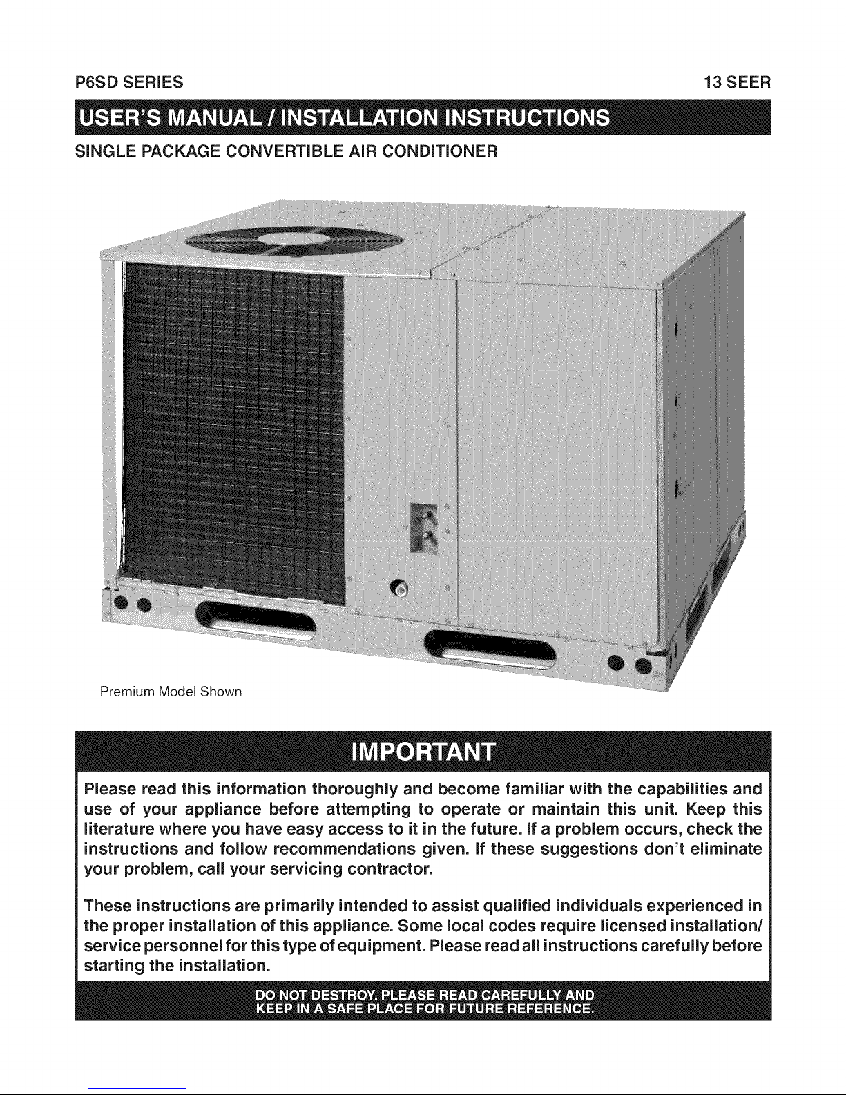
SINGLE PACKAGE CONVERTIBLE AiR CONDiTiONER
Premium Model Shown
Please read this information thoroughly and become familiar with the capabilities and
use of your appliance before attempting to operate or maintain this unit. Keep this
literature where you have easy access to it in the future. If a problem occurs, check the
instructions and follow recommendations given. If these suggestions don't eliminate
your problem, call your servicing contractor.
These instructions are primarily intended to assist qualified individuals experienced in
the proper installation of this appliance. Some local codes require licensed installation/
service personnel for this type of equipment. Please read all instructions carefully before
starting the installation.

Safety information ...................................................... 4
About the Air Conditioner ......................................... 4
Operating Instructions ............................................... 4
Cooling Operation ..................................................... 4
Heating Operation ..................................................... 4
Turning the Air Conditioner Off ................................. 4
Oper. the Indoor Blower Continuously ...................... 4
Air Conditioner Maintenance .................................... 4
Regular Cleaning ...................................................... 4
Before You Call a Technician .................................... 4
WARRANTY INFORMATION
A warranty certificate with full details is included with the
Air Conditioner. Carefully reviewthese responsibilities with
your dealer or service company. The manufacturer will not
be responsible for any costs found necessary to correct
problems due to improper setup, improper installation,
adjustments, improper operating procedure on the part
of the user, etc. Some specific examples of service calls
which are not included in the limited warranty are:
Correcting wiring problems in the electrical circuit
supplying the Air Conditioner.
Resetting circuit breakers or other switches.
Adjusting or calibrating of thermostat.
Safety information ...................................................... 5
General Information ................................................... 6
Pre - Installation Check ............................................. 6
Locating the Air Conditioner ...................................... 6
Field Connections for Electrical Power
Supply ....................................................................... 6
Air Ducts ................................................................... 6
Unconditioned Spaces ........................................... 6
Acoustical Duct Work ............................................. 6
Air Filter Requirements ............................................ 7
Air Conditioner installation ....................................... 7
Packaging Removal ................................................. 7
Rigging and Hoisting ................................................ 7
Minimum Clearance Requirements ........................... 7
Ground Level ............................................................. 7
Rooftop...................................................................... 8
Horizontal to Downflow Conversion .......................... 8
Removal of Internal Filter Rack ................................. 8
Installing Filters inthe Filter Rack ............................. 8
Removing Filters from the Filter Rack ....................... 8
Condensate Drain .................................................... 8
Electrical Wiring ......................................................... 9
Pre - Electrical Checklist ........................................... 9
Line Voltage .............................................................. 9
Grounding ................................................................. 9
Unbalanced 3-Phase Supply Voltage ..................... 10
Thermostat Connections ......................................... 10
Blower Speed .......................................................... 10
PSC Motor -208/230V ......................................... 11
PSC Motor - 460V ................................................ 11
Fixed Torque ECM Motor ..................................... 11
Optional Outdoor Thermostat ................................. 11
Optional Electric Heater Kits ................................... 11
Startup & System Check ......................................... 12
Pre - Start Checklist ................................................ 12
Start-up Procedure .................................................. 12
Air Circulation ....................................................... 12
System Cooling .................................................... 12
System Heating .................................................... 12
Refrigerant Chargmg ............................................... 12
Charging an R-410A Unit in AC Mode ..................... 12
Air Conditioner Maintenance .................................. 13
Figures & Tables ....................................................... 14
Figure 9. P6SD Air Conditioner Dimensions ........ 14
Table 4. Center of Gravity & Shipping Weights .... 14
Electrical Information .............................................. 15
Figure 10. A.C. T-Stat Connections - 230V .......... 15
Figure 11. A.C. T-Stat Connections - 460V .......... 15
Table 5. A.C. Blower Curves ................................ 16
Figure 12. Wiring Diagram - PSC Motor-
Three Phase - 208/230V ..................... 17
Figure 13. Wiring Diagram - Fixed Torque Motor -
Three Phase - 208/230V ..................... 18
Figure 14. Wiring Diagram - PSC Motor -
Single Phase - 208/230V .................... 19
Figure 15. Wiring Diagram - Fixed Torque Motor -
Single Phase - 208/230V .................... 20
Figure 16. Wiring Diagram - Fixed Torque Motor -
Three Phase - 460V ............................ 21
Figure 17. Wiring Diagram - PSC Motor -
Three Phase - 460V ............................ 22
Cooling Charging Charts ......................................... 23
Figure 18. Charging Chart for 3 Ton Units ........... 23
Figure 19. Charging Chart for 4 Ton Units ........... 23
Figure 20. Charging Chart for 5 Ton Units ........... 24
SAFETYINFORMATION
IMPORTANT:Pleasereadallinstructionsbeforeservicing
thisequipment.Payattentiontoallsafetywarningsand
anyotherspecialnoteshighlightedinthemanual.Safety
markingsareusedfrequentlythroughoutthismanualto
designateadegreeorlevelofseriousnessandshouldnot
beignored.WARNINGindicatesapotentiallyhazardous
situationthatifnotavoided,couldresultinpersonalinjury
ordeath.CAUTIONindicatesa potentiallyhazardous
situationthatifnotavoided,mayresultinminorormoderate
injuryorpropertydamage.
ABOUT THE AIR CONDITIONER
The P6 Series single packaged convertible air conditioner
is a high efficient self contained cooling unit that will cool
your home year round and provide energy saving comfort.
Additional features and benefits of the P6 air conditioner
include:
• Indoor and outdoor coils are designed to optimize heat
transfer, minimize size and cost, and increase durability
and reliability.
• Environmentally friendly R-410A Refrigerant.
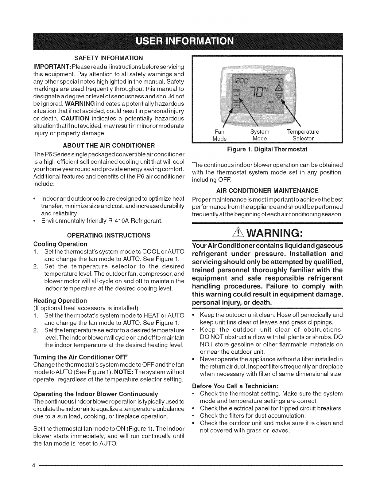
Fan System Temperature
Mode Mode Selector
Figure 1. Digital Thermostat
The continuous indoor blower operation can be obtained
with the thermostat system mode set in any position,
including OFR
AIR CONDITIONER MAINTENANCE
Proper maintenance is most important to achieve the best
performance from the appliance and should be performed
frequently at the beginning of each air conditioning season.
OPERATING INSTRUCTIONS
Cooling Operation
1. Set the thermostat's system mode to COOL or AUTO
and change the fan mode to AUTO. See Figure 1.
2. Set the temperature selector to the desired
temperature level. The outdoor fan, compressor, and
blower motor will all cycle on and off to maintain the
indoor temperature at the desired cooling level.
Heating Operation
(If optional heat accessory is installed)
1. Set the thermostat's system mode to HEAT or AUTO
and change the fan mode to AUTO. See Figure 1.
2. Set thetemperature selector to a desired temperature
level. The indoor blower willcycle on and off to maintain
the indoor temperature at the desired heating level.
Turning the Air Conditioner OFF
Change the thermostat's system mode to OFF and the fan
mode to AUTO (See Figure 1). NOTE: The system will not
operate, regardless of the temperature selector setting.
Operating the Indoor Blower Continuously
The continuous indoor blower operation is typically used to
circulate the indoorair toequalize atemperature unbalance
due to a sun load, cooking, or fireplace operation.
Set the thermostat fan mode to ON (Figure 1). The indoor
blower starts immediately, and will run continually until
the fan mode is reset to AUTO.
WARNING:
Your Air Conditioner contains liquid and gaseous
refrigerant under pressure. Installation and
servicing should only be attempted by qualified,
trained personnel thoroughly familiar with the
equipment and safe responsible refrigerant
handling procedures. Failure to comply with
this warning could result in equipment damage,
personal injury, or death.
• Keep the outdoor unit clean. Hose off periodically and
keep unit fins clear of leaves and grass clippings.
• Keep the outdoor unit clear of obstructions.
DO NOT obstruct airflow with tall plants or shrubs. DO
NOT store gasoline or other flammable materials on
or near the outdoor unit.
• Never operate the appliance without a filter installed in
the return airduct. Inspect filters frequently and replace
when necessary with filter of same dimensional size.
Before You Call a Technician:
• Check the thermostat setting. Make sure the system
mode and temperature settings are correct.
• Check the electrical panel for tripped circuit breakers.
• Check the filters for dust accumulation.
• Check the outdoor unit and make sure it is clean and
not covered with grass or leaves.

SAFETYINFORMATION
IMPORTANT:Safetymarkingsare usedfrequently
throughoutthismanualto designatea degreeorlevel
ofseriousnessandshouldnotbe ignored.WARNING
indicatesa potentiallyhazardoussituationthat if
notavoided,couldresultin personalinjuryor death.
CAUTIONindicatesapotentiallyhazardoussituationthat
ifnotavoided,mayresultinminoror moderateinjuryor
propertydamage.
/L WARNING:
Do not place combustible material on or against
the unit cabinet. Do not place combustible
materials, including gasoline and any other
flammable vapors and liquids, in the vicinity of
the unit.
WARNING:
improper installation, service, adjustment, or
maintenance may causeexplosion,fire,electrical
shock or other hazardous conditions which may
result in personal injury or property damage.
Unless otherwise noted in these instructions,
only factory authorized kits or accessories may
be used with this product.
CAUTION'.
This unit uses refrigerant R=410A. DO NOT use
any other refrigerant in this unit. Use of another
refrigerant will damage the unit.
WARNING:
Shut off all electrical power to the unit before
performing any maintenance or service on the
system. Failure to comply may result in personal
injury or death.
WARNING:
These units are fully charged with R=410A
refrigerant and ready for installation. When
a system is installed according to these
instructions, no refrigerant charging is required.
if repairs make it necessary for evacuation
and charging, it should only be attempted by
qualified, trained personnel thoroughly familiar
with this equipment. Some local codes require
licensed installation service personnel to
service this type of equipment. Under no
circumstances should the homeowner attempt
to install and/or service this equipment. Failure
to comply with this warning could result in
equipment damage, personal injury, or death.
/L WARNING:
The safety information listed below must be
followed during the installation, service, and
operation of this unit. Unqualified individuals
should not attempt to interpret these instructions
or install this equipment. Failure to follow safety
recommendations could result in possible
damage to the equipment, serious personal
injury or death.
• The installer must comply with all local codes and
regulations which govern the installation of this type
of equipment. Local codes and regulations take
precedence over any recommendations contained in
these instructions. Consult local building codes and
the National Electrical Code (ANSi CI) for special
installation requirements.
• This equipment contains liquid and gaseous refrigerant
under highpressure, installation or servicing should only
be performed by qualified trained personnel thoroughly
familiar with this type equipment.
• All electrical wiring must be completed in accordance
with local, state and national codes and regulations
and with the National Electric Code (ANSI/NFPA 70)
or in Canada the Canadian Electric Code Part 1 CSA
C.22.1.
• Installation of equipment may require brazing
operations, installer must comply with safety codes
and wear appropriate safety equipment (safety glasses,
work gloves, fire extinguisher, etc.) when performing
brazing operations.
• Installthis unitonly ina location and position as specified
on page 6. This unit is designed only for outdoor
installationsand should be located with consideration
of minimizing the length of the supply and return ducts.
Consideration should also be given to the accessibility
offuel, electric power, service access, noise, andshade.
• Follow all precautions in the literature, on tags, and
on labels provided with the equipment. Read and
thoroughly understand the instructions provided with
the equipment prior to performing the installation and
operational checkout of the equipment.
GENERALINFORMATION
PackagedAirConditionerunitsarereadyfor easyand
immediateinstallationonrooftopsorgroundlevelslabs.
Unitsareshippedfor horizontalductconnectionsand
canbeeasily converted for downflow applications. This
air conditioner is designed only for outdoor installations.
This unit has been designed and tested for capacity and
efficiency in accordance with A.R.I. Standards. This
unit will provide many years of safe and dependable
comfort, providing it is properly installed and maintained.
With regular maintenance, this unit will operate reliably
year after year. Abuse, improper use, and/or improper
maintenance can shorten the life of the appliance and
create unsafe hazards.
Pre - Installation Check
Before you install this unit, the cooling load of the area
to be conditioned must be calculated and a system of
the proper capacity selected. It is recommended that
the area to be conditioned be completely insulated
and vapor sealed.
Checkthe electrical supply and verify the power supply
is adequate for unit operation. If there is any question
concerning the power supply, contact the local power
company.
All units are securely packed at the time of shipment
and upon arrival should be carefully inspected for
damage prior to installing the equipment at the job
site. Verify coil fins are straight. If necessary, comb fins
to remove flattened or bent fins. Claims for damage
(apparent or concealed) should be filed immediately
with the carrier.
Please consult your dealer for maintenance information
and availability of maintenance contracts. Please read
all instructions before installing the unit.
........i......... ............
3 ior ooljI
C)
LU
b
Locating the Air Conditioner
• Survey the job site to determine the best location for
mounting the outdoor unit.
• Choose an appropriate location that minimizes the
length of the supply and return air ducts.
• Avoid overhead obstructions, poorly ventilated areas,
and areas subject to accumulation of debris.
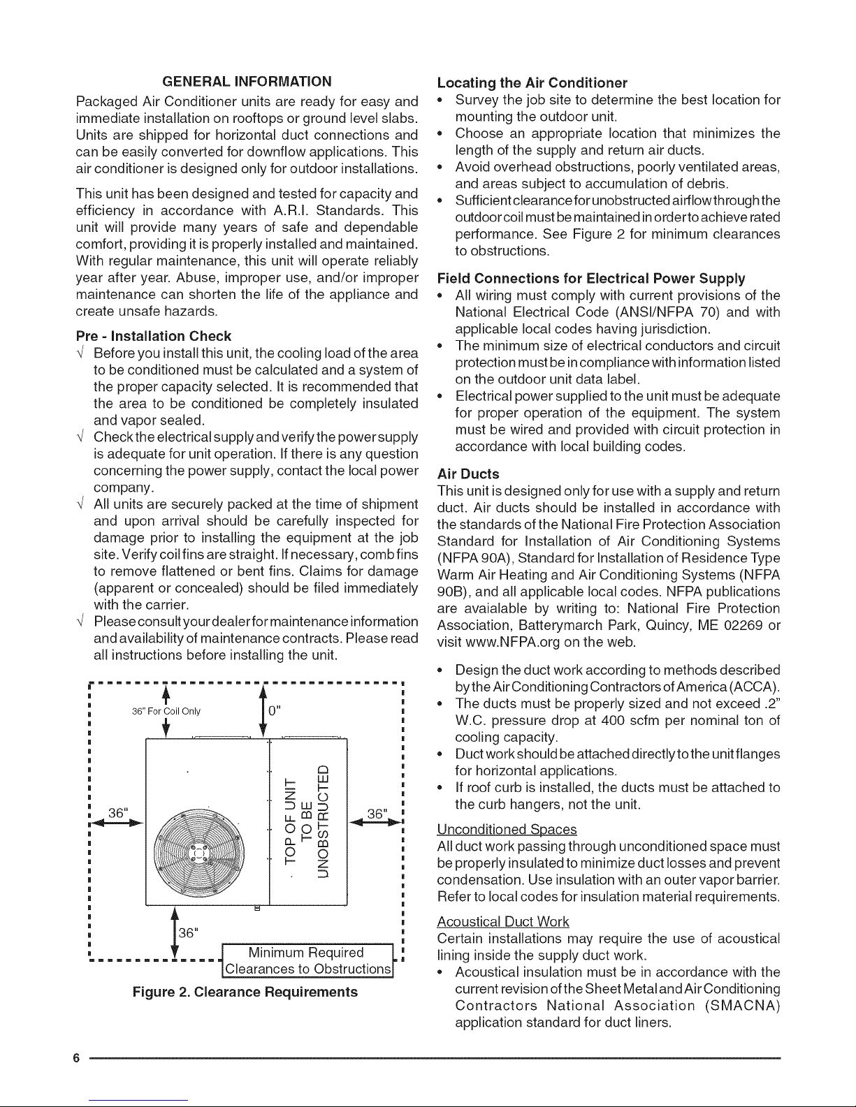
• Sufficient clearancefor unobstructed airfiowthroughthe
outdoor coil must be maintained inorderto achieve rated
performance. See Figure 2 for minimum clearances
to obstructions.
Field Connections for Electrical Power Supply
• All wiring must comply with current provisions of the
National Electrical Code (ANSVNFPA 70) and with
applicable local codes having jurisdiction.
• The minimum size of electrical conductors and circuit
protection must be incompliance with information listed
on the outdoor unit data label.
• Electrical power supplied to the unit must be adequate
for proper operation of the equipment. The system
must be wired and provided with circuit protection in
accordance with local building codes.
Air Ducts
This unit is designed only for use with a supply and return
duct. Air ducts should be installed in accordance with
the standards of the National Fire Protection Association
Standard for Installation of Air Conditioning Systems
(NFPA 90A), Standard for Installation of Residence Type
Warm Air Heating and Air Conditioning Systems (NFPA
90B), and all applicable local codes. NFPA publications
are avaialable by writing to: National Fire Protection
Association, Batterymarch Park, Quincy, ME 02269 or
visit www.NFPA.org on the web.
• Design the duct work according to methods described
bythe Air Conditioning Contractors of America (ACCA).
• The ducts must be properly sized and not exceed .2"
W.C. pressure drop at 400 scfm per nominal ton of
cooling capacity.
• Duct work should be attached directlytothe unit flanges
for horizontal applications.
• If roof curb is installed, the ducts must be attached to
the curb hangers, not the unit.
_- z
!tS.. °
......... i Minimum Required L
Figure 2. Clearance Requirements
Clearances to Obstructions|
Unconditioned Spaces
All duct work passing through unconditioned space must
be properly insulated to minimize duct losses and prevent
condensation. Use insulation with an outer vapor barrier.
Refer to local codes for insulation material requirements.
Acoustical Duct Work
Certain installations may require the use of acoustical
lining inside the supply duct work.
• Acoustical insulation must be in accordance with the
current revision ofthe Sheet Metal and Air Conditioning
Contractors National Association (SMACNA)
application standard for duct liners.

DuctliningmustbeULclassifiedbattsorblanketswith
afirehazardclassificationofFHC-25/50orless.
Fiberductworkmaybeusedinplaceofinternalduct
linersifthefiberductworkisinaccordancewiththe
currentrevisionoftheSMACNAconstructionstandard
onfibrousglassducts.Fibrousductworkandinternal
acousticalliningmustbeNFPAClass1airductswhen
testedperULStandard181forClass1ducts.
Air Filter Requirements
WARNING:
Never operate the unit without a filter in place.
Dust and lint could accumulate on internal parts,
resulting in loss of efficiency, equipment damage
and possible fire. Replace disposable filters with
the same type and size.
= Air filter(s) are not supplied and must be installed Jn
the unit or inthe return air system by the installer. Only
three phase units are equipped with an internal filter
rack assembly.
= If using an Economizer or Fresh Air Equipment, the
factory installed filter rack must be removed prior to
installation. See page 8 for removal instructions.
= All return air must pass through the filters before
entering the unit. Recommended filter sizes are listed in
Table 1.NOTE: Itisimportant that all filters be kept clean
and replaced frequently to ensure proper operation of
unit. Dirty or clogged filters will reduce the efficiency
of the unit and result Jnunit shutdowns.
= Air filter pressure drop must not exceed 0.08 inches
WC. When replacing the air filters, a suitable air filter
must be installed upstream of the evaporator coil of
the return air system.
= Downflow installations require an internal filter
accessory kit to be installed.
= Horizontal installations require the air filter system be
installed in the return air ductwork.
Unit Size internal FiJter Size
P6SD-X36 (2) 16" x 25" x 1"
P6SD-X48 or
P6SD-X60 or
Table 1. Internal Filter Size Requirements.
(2) 16" x 25" x 2"
(2) 18" x 25" x 1"
(2) 18" x 25" x 2"
AIR CONDiTiONER INSTALLATION
Packaging Removal
Remove the shipping carton and User's Manual from
the equipment. Take care not to damage the tubing
connections when removing the carton. For rooftop
installations, remove and discard the two supports
attached beneath the unit.
Rigging and Hoisting
WARNING:
To avoid the risk of property damage, personal
injury, or death, it is the rigger's responsibility
to ensure that whatever means are used to hoist
the unit are safe and adequate:
The lifting equipment must be adequate for the
load. Refer toTable 4 (page 14) for unit weights.
The unit must be lifted from the holes in the
base rails using cables or chains.
Spreader bars are required to protect the unit
and ensure even loading.
Keep the unit in an upright position at all times.
The rigging must be located outside the units
center of gravity. Refer to Figure 9 (page 14)
for locating the center of gravity.
All panels must be securely in place during
rigging and hoisting.
Minimum Clearance Requirements
P6SD units are certified as cooling equipment for
outdoor installation only. Figure 2 (page 6) displays the
minimum clearances to obstructions for both Downflow
and Horizontal discharge.
Units may be installed on wood flooring or on Class A,
B, or C roof covering material when used with bottom
supply and return air ducts. If using bottom discharge
with return air ducts, a roof curb must be installed prior
to unit installation. See Rigging and Hoisting section for
setting of the unit.
Ground Level
Ground level installations must be located according to
local building codes or ordinances and these requirements:
= Clearances must be in accordance with those shown
in Figure 2.
= A suitable mounting pad (Figure 3, page 8) must be
provided and separate from the building foundation.
The pad must be level to ensure proper condensate
disposal and strong enough to support the unit's weight.
The slab height must be a minimum of 2" (5cm) above
grade and with adequate drainage.
= Allow sufficient clearances for access to the internal
filter rack.
7
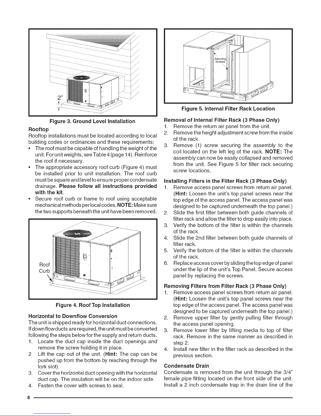
Figure 5. Internal Filter Rack Location
Figure 3. Ground Level Installation
Rooftop
Rooftop installations must be located according to local
building codes or ordinances and these requirements:
• The roof must be capable of handling the weight of the
unit. For unit weights, see Table 4 (page 14). Reinforce
the roof if necessary.
• The appropriate accessory roof curb (Figure 4) must
be installed prior to unit installation. The roof curb
must be square and level to ensure proper condensate
drainage. Please follow all instructions provided
with the kit.
• Secure roof curb or frame to roof using acceptable
mechanical methods per local codes. NOTE: Make sure
the two supports beneath the unit have been removed.
Roof
Curb
Removal of internal Filter Rack (3 Phase Only)
1. Remove the return air panel from the unit.
2. Remove the height adjustment screw from the inside
of the rack,
3. Remove (1) screw securing the assembly to the
coil located on the left leg of the rack. NOTE: The
assembly can now be easily collapsed and removed
from the unit. See Figure 5 for filter rack securing
screw locations,
Installing Filters in the Filter Rack (3 Phase Only)
1. Remove access panel screws from return air panel.
(Hint: Loosen the unit's top panel screws near the
top edge of the access panel. The access panel was
designed to be captured underneath the top panel,)
2. Slide the first filter between both guide channels of
filter rack and allow the filter to drop easily into place.
3. Verify the bottom of the filter is within the channels
of the rack.
4. Slide the 2nd filter between both guide channels of
filter rack.
5. Verify the bottom of the filter is within the channels
of the rack.
6. Replace access cover by sliding the top edge of panel
under the lip of the unit's Top Panel, Secure access
panel by replacing the screws,
Figure 4. Roof Top Installation
Horizontal to Downflow Conversion
The unit is shipped ready for horizontal duct connections.
Ifdown fiowducts are required, the unit must be converted
following the steps below for the supply and return ducts.
1. Locate the duct cap inside the duct openings and
remove the screw holding it in place.
2 Lift the cap out of the unit. (Hint: The cap can be
pushed up from the bottom by reaching through the
fork slot).
3. Cover the horizontal duct opening with the horizontal
duct cap. The insulation will be on the indoor side.
4. Fasten the cover with screws to seal.
Removing Filters from Filter Rack (3 Phase Only)
1. Remove access panel screws from return air panel.
(Hint: Loosen the unit's top panel screws near the
top edge of the access panel. The access panel was
designed to be captured underneath the top panel.)
2. Remove upper filter by gently pulling filter through
the access panel opening.
3. Remove lower filter by lifting media to top of filter
rack. Remove in the same manner as described in
step 2.
4. Install new filter in the filter rack as described in the
previous section.
Condensate Drain
Condensate is removed from the unit through the 3/4"
female pipe fitting located on the front side of the unit.
Install a 2 inch condensate trap in the drain line of the
 Loading...