

Nordyne P5RD, GP5RD-024K, GP5RD-030K, GP5RD-036K, GP5RD-042K Installation Manual
...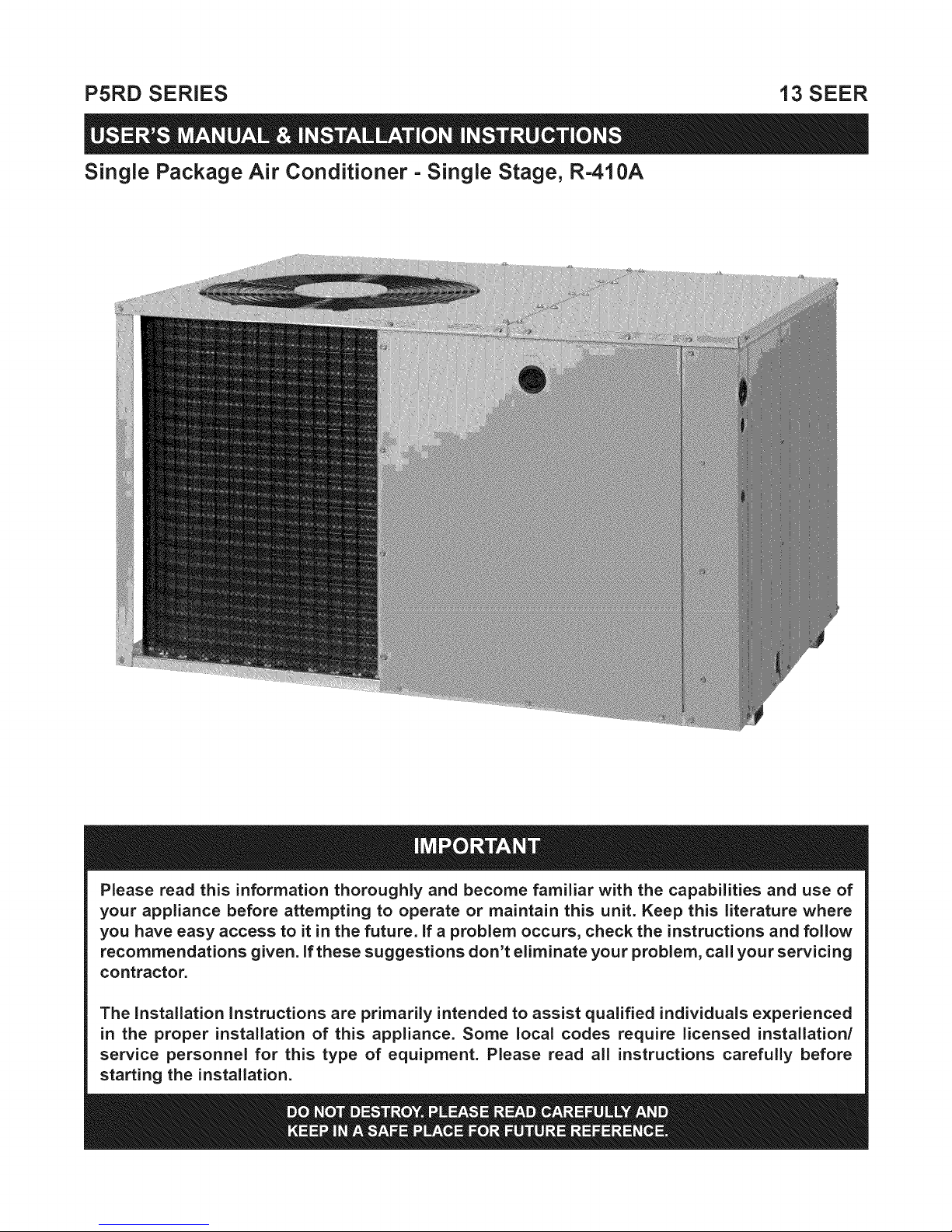
P5RD SERIES 13 SEER
Single Package Air Conditioner =Single Stage, R-410A
Please read this information thoroughly and become familiar with the capabilities and use of
your appliance before attempting to operate or maintain this unit. Keep this literature where
you have easy access to it in the future, if a problem occurs, check the instructions and follow
recommendations given, if these suggestions don't eliminate your problem, call your servicing
contractor.
The Installation instructions are primarily intended to assist qualified individuals experienced
in the proper installation of this appliance. Some local codes require licensed installation/
service personnel for this type of equipment. Please read all instructions carefully before
starting the installation.

Important Safety Information .................................... 3
Operating Instructions ............................................... 3
Cooling Operation ..................................................... 3
Heating Operation ..................................................... 3
Turning the Air Conditioner Off .................................. 3
Operating the Indoor Blower Continuously ................ 3
Air Conditioner Maintenance ..................................... 3
Troubleshooting .......................................................... 3
WARRANTY IN FORMATION
A warranty certificate with full details is included with the
Air Conditioner. Carefully reviewthese responsibilities with
your dealer or service company.The manufacturer will not
be responsible for any costs found necessary to correct
problems due to improper setup, improper installation,
adjustments, improper operating procedure on the part
of the user, etc. Some specific examples of service calls
which are not included in the limited warranty are:
• Correcting wiring problems in the electrical circuit
supplying the Air Conditioner.
• Resetting circuit breakers or other switches.
• Adjusting or calibrating of thermostat.
Important Safety Information .................................... 4
General Information ................................................... 5
Before You Install this Unit ......................................... 5
Locating the Air Conditioner ..................................... 5
Minimum Clearance Requirements .......................... 5
Service Access Clearances .................................. 5
Clearances to Combustible Materials ................... 5
Air Duct System ........................................................ 5
Air Conditioner Installation ....................................... 6
Unpacking the Unit ................................................... 6
Installing Return & Supply Collars ............................. 6
Supply Duct ........................................................... 6
Return Duct ........................................................... 7
Locating & Installing the Return Air Assembly .......... 7
Connecting the Return & Supply Air Flexible
Ducts ......................................................................... 7
Locating & Installing the Supply Dampers ................. 7
Condensate Drainage .............................................. 8
Electrical Connections ............................................... 8
Pre - Electrical Checklist ........................................... 8
Line Voltage ............................................................... 8
Overcurrent Protection .............................................. 9
Grounding .................................................................. 9
Thermostat / Low Voltage Connections ..................... 9
Cooling Thermostat ................................................ 9
Heat/Cool Thermostat ............................................ 9
Blower Speed ......................................................... 10
Standard PSC Motor ............................................ 10
High Efficiency ECM Motor .................................. 10
Startup & Adjustments ............................................ 10
Pre - Start Checklist ................................................ 10
Start - Up Procedure ............................................... 10
System Cooling .................................................... 10
Emergency Heat .................................................. 11
Adjustment of Refrigerant Charge ........................... 11
Charging an R410A Unit in AC Mode with Outdoor
Temperatures above 55 ° F...................................... 12
Air Conditioner Maintenance ................................... 12
Component Functions ............................................. 12
High Pressure Switch .............................................. 12
Low Pressure Switch ............................................... 12
Replacement Parts ................................................... 12
Figures & Tables ....................................................... 13
Figure 10 - Phys. Data & Unit Dimensions ........... 13
Wiring Diagrams ...................................................... 14
Figure 11 - P5RD -w/ECM Motor ....................... 14
Figure 12 - P5RD -w/PSC Motor ........................ 15
Refrigerant Charging Tables .................................... 16
Table 4 - P5RD-024K (2 Ton Units) ...................... 16
Table 5 - P5RD-030K (2.5 Ton Units) ................... 16
Table 6 - P5RD-036K (3 Ton Units) ...................... 17
Table 7 - P5RD-042K (3.5 Ton w/X-13 Motor) ..... 17
Table 8 - P5RD-042KA (3.5 Ton w/PSC Motor)... 18
Table 9 - P5RD-048K (4 Ton Units) ...................... 18
Figure 13 - P5RD-048KA (4 Ton w/TXV Valve) ...19
Table 10 - P5RD-060K 5 Ton Units ...................... 19
Installation / Performance Checklist ....................... 20

iMPORTANT SAFETY INFORMATION
Safety markings are used to designate a degree or level
of seriousness and should not be ignored. WARNING
indicates a potentially hazardous situation that if not
avoided, could result in personal injuryor death. CAUTION
indicates a potentially hazardous situation that if not
avoided, may result in minor or moderate injuryor property
damage.
OPERATING INSTRUCTIONS
NOTE: Thermostat styles vary. Some models may not
include the AUTO mode and others will have the AUTO
in place of the HEAT and COOL. Others may include all
three. Please refer to the thermostat manufacturer's User
manual for detailed programming instructions.
Cooling Operation
1.Set the thermostat's system mode to COOL or AUTO
and change the fan mode to AUTO. See Figure 1.
2. Set the temperature selector to the desired temperature
level.The outdoor fan, compressor, and blower motorwill
all cycle on and off to maintain the indoor temperature
at the desired cooling level.
Heating Operation
(if optional heater kit is installed)
1.Set the thermostat's system mode to HEAT or AUTO
and change the fan mode to AUTO. See Figure 1.
2. Set the temperature selector to the desired temperature
level. The outdoor fan, blower motor, and heater kit will
cycle on and off to maintain the indoor temperature at
the desired heating level.
Turning the Air Conditioner OFF
Change the thermostat's system mode to OFF and the fan
mode toAUTO (See Figure 1).NOTE: The system will not
operate, regardless of the temperature selector setting.
Operating the Indoor Blower Continuously
The continuous indoor blower operation istypically used to
circulate the indoor airto equalize a temperature unbalance
due to a sun load, cooking, or fireplace operation.
Set the thermostat fan mode to ON (Figure 1).The indoor
blower starts immediately, and will run continually until
the fan mode is reset to AUTO.
The continuous indoor blower operation can be obtained
with the thermostat system mode set in any position,
including OFF.
AIR CONDITIONER MAINTENANCE
Proper maintenance is most important to achieve the best
performance from the appliance and should be performed
frequently atthe beginning ofeach air conditioning season.
zLWARNING:
Your Air Conditioner contains liquid and
gaseous refrigerant under pressure, installation
and servicing should only be attempted by
qualified, trained personnel thoroughly familiar
with the equipment and safe responsible
refrigerant handling procedures. Failure to
comply with this warning could result in
equipment damage, personal injury, or death.
• Keep the unit clean. Hose off periodically and keep
unit fins clear of leaves and grass clippings.
• Keep the unit clear of obstructions. DO NOT obstruct
airflow with tall plants or shrubs. DO NOT store gasoline
or other flammable materials on or near the unit.
• Never operate the appliance without a filter installed in
the return air duct. Inspect filters frequently and replace
when necessary with filter of same dimensional size.
FAN SYSTEM TEMPERATURE
MODE MODE SELECTOR
Figure 1. Digital Thermostat
TROUBLESHOOTING
If the unit fails to operate, check the following:
• Check the thermostat setting. Make sure the system
mode and temperature settings are correct.
• Check the electrical panel for tripped circuit breakers.
• Check the filters for dust accumulation.
• Check the unit and make sure it is clean and not covered
with grass or leaves.
• If the items above don't resolve your problems, then
call your nearest service technician.
iMPORTANT SAFETY iNFORMATiON
Please read all instructions before servicing this equipment.
Pay attention to all safety warnings and any other special
notes highlighted in the manual. Safety markings are
used frequently throughout this manual to designate a
degree or level of seriousness and should not be ignored.
WARNING indicates a potentially hazardous situation that
if not avoided, could result in personal injury or death.
CAUTION indicates a potentially hazardous situation that
if not avoided, may result in minor or moderate injury or
property damage.
ZLWARNING:
Shut off all electrical power to the unit before
performing any maintenance or service on the
system. Failure to comply may result in personal
injury or death.
ZLWARNING:
Unless noted otherwise in these instructions,
only factory authorized parts or accessory
kits may be used with this product, improper
installation,service, adjustment, or maintenance
may cause explosion, fire, electrical shock or
other hazardous conditions which may result
in personal injury or property damage.
ZLWARNING:
P5RD units are fully charged with R-410A
refrigerant and ready for installation. When
a system is installed according to these
instructions, no refrigerant charging is required.
if repairs make it necessary for evacuation
and charging, it should only be attempted
by qualified, trained personnel thoroughly
familiar with this equipment. Some local codes
require licensed installation service personnel
to service this type of equipment. Under no
circumstances should the equipment owner
attempt to install and/or service this equipment.
Failure to comply with this warning could result
in equipment damage, personal injury, or death.
CAUTION:
This unit uses refrigerant R-410A. DO NOT use
any other refrigerant in this unit. Use of another
refrigerant will damage the unit.
WARNING:
The information listed below must be followed
during the installation, service, and operation
of this unit. Unqualified individuals should
not attempt to interpret these instructions or
install this equipment. Failure to follow safety
recommendations could result in possible
damage to the equipment, serious personal
injury or death.
• The installer must comply with all local codes and
regulations which govern the installation of this type
of equipment. Local codes and regulations take
precedence over any recommendations contained in
these instructions. Consult local building codes and
the National Electrical Code (ANSI Cl) for special
installation requirements.
• All electrical wiring must be completed in accordance
with local, state and national codes and regulations
and with the National Electric Code (ANSI/NFPA 70)
or in Canada the Canadian Electric Code Part 1 CSA
C.22.1.
• This equipment contains liquid and gaseous refrigerant
under high pressure. DO NOT USE ANY PORTION OF
THE CHARGE FOR PURGING OR LEAK TESTING.
Installation or servicing should only be performed by
qualified trained person nel thoroughly familiar with this
type equipment.
• This unit is designed for outdoor installations only and
should be located in a position as shown on page 5.
• Follow all precautions in the literature, on tags, and
on labels provided with the equipment. Read and
thoroughly understand the instructions provided with
the equipment prior to performing the installation and
operational checkout of the equipment.
GENERAL iNFORMATiON
The P5RD packaged air conditioner is designed only
for outdoor ground level installations and can be readily
connected to the high static duct system ofa home.This unit
has been tested for capacity and efficiency in accordance
with A.R.I. Standards and will provide many years of safe
and dependable comfort, providing it is properly installed
and maintained. Abuse, improper use, and/or improper
maintenance can shorten the life of the appliance and
create unsafe hazards.
Toachieve optimum performance and minimize equipment
failure, it is recommended that periodic maintenance be
performed on this unit. The ability to properly perform
maintenance on this equipment requires certain
mechanical skills and tools.
BeforeYou Install this Unit
_/ The cooling load of the area to be conditioned must be
calculated and a system of the proper capacity selected.
It is recommended that the area to be conditioned be
completely insulated and vapor sealed.
_/ Check the electrical supply and verify the power supply
is adequate for unit operation. If there is any question
concerning the power supply, contact the local power
company.
_/ All units aresecurely packed at the time of shipment and
upon arrival should be carefully inspected for damage
prior to installing the equipment at the job site. Verify
coil fins are straight. If necessary, comb fins to remove
flattened or bent fins. Claims for damage (apparent or
concealed) should be filed immediatelywith the carrier.
_/ Please consult your dealer for maintenance information
and availability of maintenance contracts. Please read
all instructions before installing the unit.
• Sufficient clearance for unobstructed airflow through
the outdoor coil must be maintained in order to achieve
rated performance.
• Consideration should also be given to availability of
electric power, service access, noise, and shade.
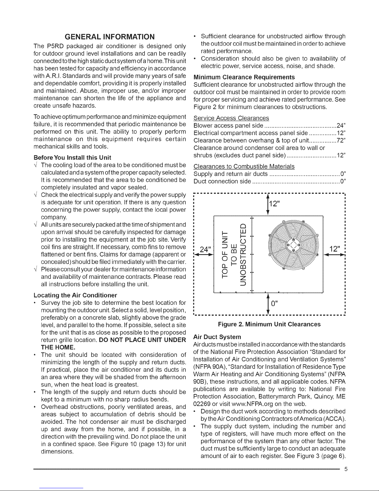
Minimum Clearance Requirements
Sufficient clearance for unobstructed airflow through the
outdoor coil must be maintained in order to provide room
for proper servicing and achieve rated performance. See
Figure 2 for minimum clearances to obstructions.
Service Access Clearances
Blower access panel side .......................................... 24"
Electrical compartment access panel side ................ 12"
Clearance between overhang & top of unit................ 72"
Clearance around condenser coil area to wall or
shrubs (excludes duct panel side) ............................. 12"
Clearances to Combustible Materials
Supply and return air ducts ......................................... 0"
Duct connection side ................................................... 0"
........................................
C3
H- W
b
u
©©
© ©
Locating the Air Conditioner
• Survey the job site to determine the best location for
mounting the outdoor unit. Select a solid, level position,
preferably on aconcrete slab, slightly above the grade
level, and parallel to the home. If possible, select a site
for the unit that is as close as possible to the proposed
return grille location. DO NOT PLACE UNIT UNDER
THE HOME.
• The unit should be located with consideration of
minimizing the length of the supply and return ducts.
If practical, place the air conditioner and its ducts in
an area where they will be shaded from the afternoon
sun, when the heat load is greatest.
• The length of the supply and return ducts should be
kept to a minimum with no sharp radius bends.
• Overhead obstructions, poorly ventilated areas, and
areas subject to accumulation of debris should be
avoided. The hot condenser air must be discharged
up and away from the home, and if possible, in a
direction with the prevailing wind. Do not place the unit
in a confined space. See Figure 10 (page 13) for unit
dimensions.
Im=mm==mm=mmm=mm==mm== =mmm=mm==mm==mm=mmm=mm
O"
Figure 2. Minimum Unit Clearances
Air Duct System
Air ducts must be installed in accordance with the standards
of the National Fire Protection Association "Standard for
Installation of Air Conditioning and Ventilation Systems"
(NFPA 90A), "Standard for Installation of Residence Type
Warm Air Heating and Air Conditioning Systems" (NFPA
90B), these instructions, and all applicable codes. NFPA
publications are available by writing to: National Fire
Protection Association, Batterymarch Park, Quincy, ME
02269 or visit www.NFPA.org on the web.
• Design the duct work according to methods described
by theAir Conditioning Contractors of America (ACCA).
• The supply duct system, including the number and
type of registers, will have much more effect on the
performance of the system than any other factor. The
duct must be sufficiently large to conduct an adequate
amount of air to each register. See Figure 3 (page 6).
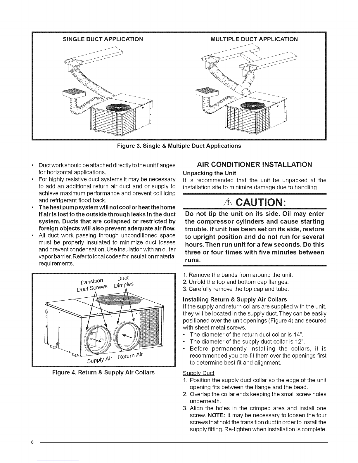
SINGLE DUCT APPLiCATiON MULTIPLE DUCT APPLiCATiON
Figure 3. Single & Multiple Duct Applications
• Ductworkshould be attached directlytothe unitflanges
for horizontal applications,
• For highly resistive duct systems it may be necessary
to add an additional return air duct and or supply to
achieve maximum performance and prevent coil icing
and refrigerant flood back.
• The heat purnpsysternwill notcool or heatthe home
if air is lost to the outside through leaks in the duct
system. Ducts that are collapsed or restricted by
foreign objects will also prevent adequate air flow,
• All duct work passing through unconditioned space
must be properly insulated to minimize duct losses
and prevent condensation. Use insulation with an outer
vapor barrier. Refer to local codes for insulation material
requirements,
Transition Duct
Duct ScreWS Dimples
Supply Air
Figure 4. Return & Supply Air Collars
AIR CONDITIONER INSTALLATION
Unpacking the Unit
It is recommended that the unit be unpacked at the
installation site to minimize damage due to handling,
CAUTION'.
Do not tip the unit on its side. Oil may enter
the compressor cylinders and cause starting
trouble, if unit has been set on its side, restore
to upright position and do not run for several
hours.Then run unit for a few seconds. Do this
three or four times with five minutes between
runs,
1. Remove the bands from around the unit.
2. Unfold the top and bottom cap flanges.
3. Carefully remove the top cap and tube,
Installing Return & Supply Air Collars
If the supply and return collars are supplied with the unit,
they will be located in the supply duct.They can be easily
positioned over the unit openings (Figure 4) and secured
with sheet metal screws.
• The diameter of the return duct collar is 14".
• The diameter of the supply duct collar is 12".
• Before permanently installing the collars, it is
recommended you pre-fit them over the openings first
to determine best fit and alignment,
Supply Duct
1. Position the supply duct collar so the edge of the unit
opening fits between the flange and the bead.
2. Overlap the collar ends keeping the small screw holes
underneath.
3. Align the holes in the crimped area and install one
screw. NOTE: It may be necessary to loosen the four
screws that hold the transition duct inorder to install the
supply fitting, Re-tighten when installation is complete,
 Loading...