

Nordyne P4 Installation Manual

USER'S MANU AL/INST ALLATION INSTRUCTIONS
P4 Series
Single Package Convertible Air Conditioner
TM
Single Package Convertible Air Conditioner
These instructions are primarily intended to assist qualified individuals
experienced in the proper installation of heating and/or air conditioning appliances. Some local codes require licensed installation/service personnel for this
type equipment. All installations must be in accordance with these instructions
and with all applicable national and local codes and standards.
Read these instructions thoroughly before starting the installation. Follow all
precautions and warnings contained within these instructions and on the unit.
IMPORTANT

2

OWNER INFORMATION
OPERATING INSTRUCTIONS
To Turn On Air Conditioner
If you have a heating/cooling thermostat:
1. Set the system switch to “Cool”.
2. Set the thermostat at the temperature level
you desire.
3. Turn the power on. Your air conditioner should
start as soon as room temperature rises
above the setting on the thermostat.
If you have one thermostat for heating and
another for cooling, they must be interlocked
to prevent simultaneous operation: (See
Figure 1)
1. Turn the heating thermostat to its lowest
possible setting.
2. If the cooling thermostat has an “On/Off”
switch, turn it “On.”
3. Set the cooling thermostat to the desired
temperature.
4. Turn the power on. Your air conditioner
should start when room temperature
exceeds the thermostat setting.
To Shut Off Air Conditioner
If you have a heating/cooling thermostat:
1. Turn the system switch to “Heat” or “Off”.
2. Turn the thermostat to the desired heating
temperature setting.
3. If you are turning your air conditioner off for
the winter or an extended period, shut off the
power to the air conditioner.
If you have one thermostat for heating and
another for cooling, they must be interlocked
to prevent simultaneous operation:
Otherwise, follow these simple rules:
1. Never run your system without filter. If you
do, the cooling coils will get dirty and may
become clogged.
2. Set your thermostat at the comfort level you
wish – and then leave it alone. Let it control
the operation of the air conditioning system.
If you get chilly, turn it up a degree at a time
until comfort is restored.
3. It takes longer for an air conditioner to cool
your dwelling than it does for your furnace to
heat it. So. . . don’t turn the unit on and expect
a dramatic drop in temperature, at least not
right away. If your home is hot and humid, the
temperature will drop slowly.
4. Check your filters every ten days in summer
to see if they are dirty. To keep them clean,
use a mild solution of detergent and water on
washable types. Replace non washable
filters.
5. Keep your condenser coil clean. You can
hose it down when it gets dirty.
If your air conditioner isn’t working:
1. Make sure the fuses are not blown or that
your circuit breakers are on.
2. See that your thermostat is set at the desired
temperature and that your system’s switch is
on “Cool”.
3. For free air flow, make sure your return
register is not covered and that the filter is
clean.
4. Check the condenser coil and make sure it is
clean and not clogged with grass or leaves.
If your air conditioner still isn’t working, call your
nearest distributor.
Cooling
Thermostat
R
Furnace
Thermostat
R
1. Turn your cooling thermostat “Off” or to its
highest setting.
2. Turn the heating thermostat to the desired
temperature.
3. If you are turning your air conditioner off for
the winter or an extended period, shut off the
power to the air conditioner.
BEFORE YOU CALL A SERVICEMAN
Let your serviceman check your system at the
start of each air conditioning season. He will
make sure it’s working right, clean or change
filters and make any needed adjustments.
Double Throw
Double Pole Switch
To Air Conditioner
To Furnace
Figure 1. Thermostat Interlock System
3
SPECIFICATIONS
Packaged Air Conditioners are designed for
outdoor rooftop or ground level slab installations.
The units are shipped ready for horizontal duct
connections and are easily converted for
downflow applications.
All models are shipped from the factory with the
following:
hazard and severity are described on each label
or tag.
Pressures Within The System — This
equipment contains liquid and gaseous
refrigerant under high pressure. Installation or
servicing should only be performed by qualified
trained personnel thoroughly familiar with this
type equipment.
1. Zero clearance to combustibles.
2. Multi-speed direct-drive blower.
3. Compressor Anti-short-cycle timer (single
phase models only).
4. Blower Speed Relay.
5. Horizontal or Downflow duct connections.
The unit dimensions are shown in Figure 2.
Optional field-installed electric heater kits are
available in 5 kw through 20 kw heating
capacities. A separate installation instruction
document for the electric heaters and their
application accompanies this one. A single stage
cooling 24VAC thermostat should be used with
these units. If electric heat will be installed, a
single-stage cooling, single stage heating
thermostat will be required.
SAFETY CONSIDERATIONS
It is the responsibility of the installer to ensure
that the installation is made in accordance with
all applicable local and national codes.
!
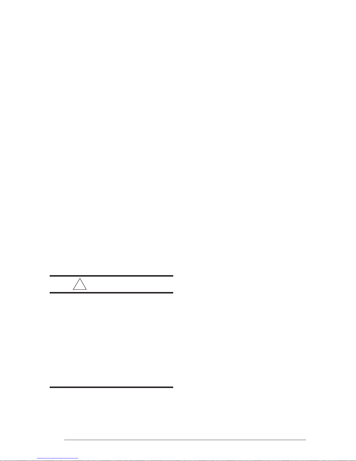
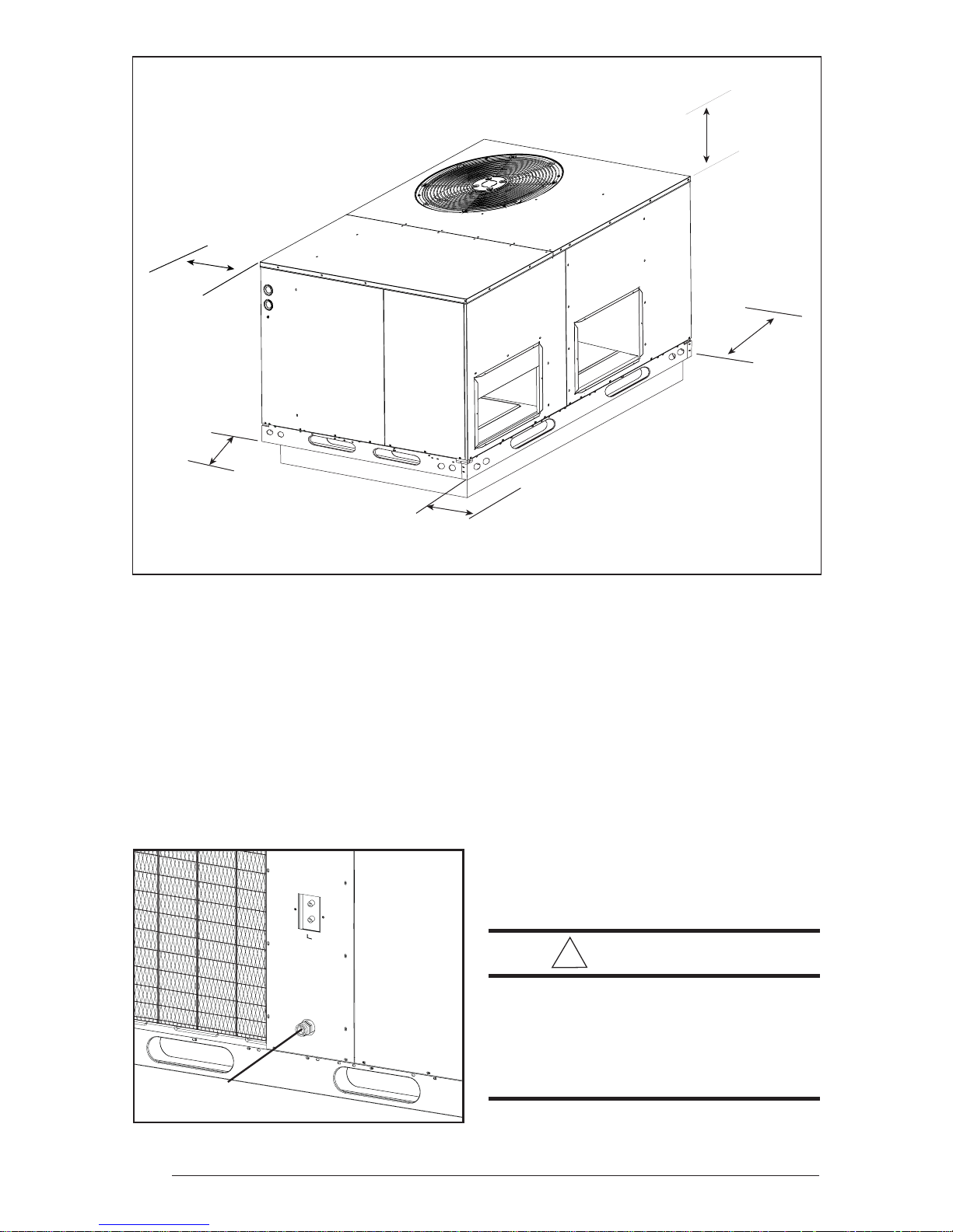
W ARNING:
Improper installation, service,
adjustment, or maintenance may
cause explosion, fire, electrical shock
or other hazardous conditions which
may result in personal injury or
property damage. Unless otherwise
noted in these instructions, only
factory authorized kits or accessories
may be used with this product. Noncompliance may void the unit’s
warranty.
Labels, Tags — When working with this
equipment, follow all precautions in the literature,
on tags, and on labels provided with the unit
and/or approved field installed kits. The type of
INSTALLATION REQUIREMENTS
Equipment Check — Before beginning the
installation, verify that the unit model is correct
for the job. The unit model number is printed on
the data label. All units have been securely
packaged at the point of shipment. After
unpacking the unit, carefully inspect it for
apparent and concealed damage. Claims for
damage should be filed with the carrier by the
consignee.
Requirements and Codes — The installer must
comply with all local codes and regulations
which govern this type equipment. Local codes
and regulations take precedence over any
recommendations contained in these
instructions. All electrical wiring must be made
in accordance with local codes and regulations
and with the National Electric Code (ANSI/
NFPA 70) or in Canada the Canadian Electric
Code Part 1 CSA C.22.1. Air Ducts must be
installed in accordance with the standards of the
National Fire Protection Association “Standards
for Installation of Air Conditioning and Ventilation
Systems” (NFPA 90A), “Standard for Installation
of Residence Type Warm Air Heating and Air
Conditioning Systems” (NFPA 90B), these
instructions and all applicable local codes.
NFPA publications are available by writing:
National Fire Protection Association
Batterymarch Park
Quincy, Maine 02269
Unit Location — This air conditioner is designed
only for outdoor installations. Choosing the
location of the unit should be based on minimizing
the length of the supply and return ducts.
Consideration should also be given to availability
of electric power, service access, noise, and
shade. Sufficient clearance for unobstructed
airflow through the outdoor coil must be
maintained in order to achieve rated performance
See Figure 3 for minimum clearances to
obstructions.
4

Center of Gravity Height (in inches)
Model No. Unit
P4SD Weight with base rails without base rails
036
048
060
405 29.5 26.0 37.7 35.3
415 29.5 26.5 37.7 35.3
480 30.0 27.5 41.7 39.3
AB
C
24.9
3/4" NPT Female
Drain Connector
DOWNFLOW
SUPPLY DUCT
OPENING
47.5
13.5
16.0
CG
16.0
13.5
B
13.3
12.0
23.5
A
DOWNFLOW
RETURN DUCT
OPENING
12.0
Top View
1.8
1.75 Ø Power Entry (Capped)
1.25 Ø Power Entry
13.5
4.0
CONDENSING
COIL
14.7
5.0
SUPPLY
13.5
8
16.0
13.45
RETURN
16.0
30
27.2
23.6
0.88 Ø Control Wiring Entry
C
Side View
4.00
11.75 22.75
Figure 2. Dimensions
55.8
Back View
5
36"
72"
36"
36"
0"
Figure 3. Minimum Clearances
Air Filter — A suitable air filter must be installed
in the return air system. Air filter pressure drop
must not exceed 0.08 inches w.c.
Condensate Drain — Condensate is removed
from the unit through the 3/4" female pipe fitting
located on the front side of the unit. (See Figure
4.) Install a 2 inch condensate trap in the drain
line of the same size and prime with water.
When connecting rigid drain line, hold the female
fitting with a wrench to prevent twisting. Do not
Condensate Drain
over-tighten! Refer to local codes and
restrictions for proper condensate disposal
requirements.
UNIT INSTALLATION
Ground Level — When installing the unit at
ground level, provide a concrete mounting
pad separate from the building foundation.
The pad must be level to insure proper
condensate disposal and strong enough to
support the unit’s weight. Refer to Figure 2 .
Make sure the slab is a minimum of 2" above
the grade and in an area that drains well.
(Figure 5)
!
W ARNING:
To avoid the risk of property damage
or personal injury; it is the rigger’s
responsibility to insure that whatever
means are used to hoist the unit are
safe and adequate.
Figure 4. Condensate Drain
6
 Loading...