

Nordyne P3RD-042K, P3RD-024K, P3RD-036K, P3RD-030K, P3RD-060K Owner's Manual
...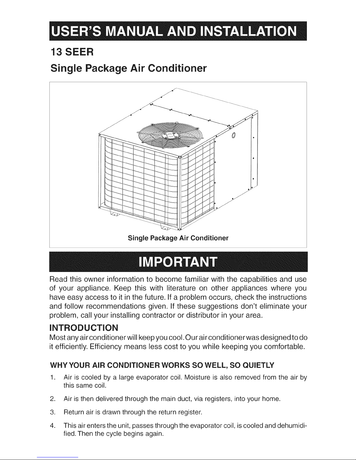
13 SEER
Single Package Air Conditioner
Single Package Air Conditioner
Read this owner information to become familiar with the capabilities and use
of your appliance. Keep this with literature on other appliances where you
have easy access to it in the future. If a problem occurs, check the instructions
and follow recommendations given. If these suggestions don't eliminate your
problem, call your installing contractor or distributor in your area.
INTRODUCTION
Most any air conditioner will keep you cool. Our air conditioner was designed to do
it efficiently. Efficiency means less cost to you while keeping you comfortable.
WHY YOUR AIR CONDITIONER WORKS SO WELL, SO QUIETLY
1. Air is cooled by a large evaporator coil. Moisture is also removed from the air by
this same coil.
2. Air is then delivered through the main duct, via registers, into your home.
3. Return air is drawn through the return register.
4. This air enters the unit, passes through the evaporator coil, is cooled and dehumidi-
fied. Then the cycle begins again.

SECTION 1.
OWNER iNFORMATiON
make sure it's working right, clean or change
filters and make any needed adjustments.
OPERATING iNSTRUCTiONS
ToTurn On Air Conditioner
ff you have a heating/cooling thermostat:
1. Set the system switch to "Cool."
2. Set the thermostat at the temperature level
you desire.
3. Turn the power on. Your air conditioner
should start as soon as room temperature
rises above the setting on the thermostat.
ff you have one thermostat for heating
and another for cooling, they must be
interlocked to prevent simultaneous
operation (See Figure 1):
1. Turn the heating thermostat to its lowest
possible setting.
2. If the cooling thermostat has an "On/Off"
switch, turn it "On."
3. Set the cooling thermostat to the desired
temperature.
4. Turn the power on. Your air conditioner
should start when room temperature ex-
ceeds the thermostat setting.
To Shut Off Air Conditioner
ff you have a heating/cooling thermostat:
1. Turn the system switch to "Heat" or "Off."
2. Turn the thermostat to the desired heating
temperature setting.
3. Ifyou are turning your air conditioner off for
the winter or an extended period, shut off
the power to the air conditioner.
ff you have one thermostat for heating
and another for cooling, they must be
interlocked to prevent simultaneous
operation (See Figure 1):
In addition, follow these simple rules:
1. Never run your system without filter. If you
do, the cooling coils will get dirty and may
become clogged.
2. Set your thermostat at the comfort level you
wish -- and then leave it alone. Let it control
the operation of the air conditioning system.
If you get chilly, turn it up a degree at a time
until comfort is restored.
3. It takes longer for an air conditioner to cool
your dwelling than it does for your furnace
to heat it. So... don't turn the unit on and
expect a dramatic drop in temperature, at
least not right away. If your home is hot and
humid, the temperature will drop slowly.
4. Check your filters every ten days in summer
to see if they are dirty. To keep them clean,
use a mild solution of detergent and water
on washable types. Replace non washable
filters.
5. Keep your outdoor condenser coil clean.
You can hose it down when it gets dirty.
ff your air conditioner isn't working:
1. Make sure the fuses are not blown or that
your circuit breakers are on.
2. Seethatyourthermostatissetatthedesired
temperature and that your system's switch
is on "Cool."
3. For free air flow, make sure your return
register is not covered and that the filter is
clean.
4. Checkthe outdoor condenser coil and make
sure it is clean and not clogged with grass
or leaves.
If your air conditioner still isn't working, call your
nearest distributor.
Cooling
Thermostat
f
Furnace
Thermostat
1. Turn your cooling thermostat "Off" or to its
highest setting.
2. Turn the heating thermostat to the desired
temperature.
3. Ifyou are turning your air conditioner off for
the winter or an extended period, shut off
the power to the air conditioner.
BEFORE YOU CALL A SERVICEMAN
Let your serviceman check your system at the
start of each air conditioning season. He will
2
) R()_ R() ()
4_
Double Throw
Double Pole Switch
To Air Conditioner To Furnace
Figure 1. Thermostat interlock System

SECTION 2.
iNSTALLER iNFORMATiON
GENERAL
Read the following instructions completely
before performing the installation.
These instructions are for the use of qualified
personnel specially trained and experienced
in the installation of this type of equipment
and related system components. Some states
require installation and service personnel to
be licensed. Unqualified individuals should not
attempt to interpret these instructions or install
this equipment.
The single packaged air conditioners are de-
signed for outdoor installation only and can be
readily connected into the high static duct system
of a home. The only connections needed for
installation are the supply and return ducts, the
line voltage, and thermostat wiring. A complete
air conditioning system typically consists of:
. Single Package Air Conditioner
. Home Fittings Kit
. Unit Fittings Kit
. Thermostat
Inspecting Equipment: All units are securely
packed at the time of shipment and, upon arrival,
shou Id be carefully inspected for damage. Claims
for damage (apparent or concealed) should be
filed immediately with the carrier.
INSTALLATION
1. SELECTTHE BEST LOCATION FORTHE
AIR CONDITIONING UNIT
iMPORTANT: DO NOT PLACE UNiT UNDER
THE HOME.
, Select a solid, level position, preferably on a
concrete slab, slightly above the grade level,
and parallel to the home.
. The hot condenser air must be discharged
up and away from the home, and if possible,
in a direction with the prevailing wind.
Do not place the unit in a confined space.
. if practical, place the air conditioner where it
and the ducts will be shaded from the after-
noon sun when the heat load is greatest.
Try to select a site for the unit that is as close
as possible to the proposed return grille loca-
tion.
. Keep in mind that the length of the supply and
return ducts should be kept to a minimum with
no sharp radiused bends.
The single package air conditioner is completely
assembled, factory wired, and factory run tested.
The units are ready for easy and immediate
installation.
PRE-INSTALLATION CHECK
Before any installation is attempted, the cool-
ing load of the area to be conditioned must be
calculated and a system of the proper capacity
selected. It is recommended that the area to
be conditioned be completely insulated and
vapor sealed.
The installer should comply with all local codes
and regulations which govern the installation
of this type of equipment. Local codes and
regulations take precedence over any recom-
mendations contained in these instructions.
Consult local building codes and the National
Electrical Code (ANSI CI) for special installation
requirements.
The electrical supply should be checked to de-
termine if adequate power is available. If there
is any question concerning the power supply,
contact the local power company.
2. UNPACKTHE UNIT
It is recommended that the unit be unpacked
at the installation site to minimize damage due
to handEing.
CAUTION:
Do not tip the unit on its side. Oil
may enter the compressor cylinders
and cause starting trouble, if unit has
been set on its side, restore to upright
position and do not run for several
hours.Then run unit for afew seconds.
Do this three or four times with five
minutes between runs.
a. Remove the bands from around the unit.
b. Unfold the top and bottom cap flanges.
c. Carefully remove the top cap and tube.

Figure 2. Minimum Unit Clearances
3. CLEARANCES
Minimum clearances, as specified in Figure
2, MUST be maintained from adjacent struc-
tures to provide room for proper servicing
and air circulation.
Do NOT install unit in a confined or recessed
area that will allow discharge air from the unit
to re-circulate into the condenser air inlet,
through the coil.
Service Access Clearance:
Blower access panel side .......................... 24"
Electrical compartment access panel side... 12"
Clearance between overhang and top of
unit ......................................................... 72"
Clearance around condenser coil area to wall
or shrubs (excludes duct panel side) .......... 12"
Minimum clearance to combustible materials:
Combustible Base (Wood or Class A, B, or C
roof Covering material) ............................... 0"
Supply and Return Air Ducts ....................... 0"
Duct Connection side .................................. 0"
DUCT REQUIREMENTS
The supply duct system, including the number
and type of registers, will have much more ef-
fect on the performance of an air conditioning
system then any other factor. The duct must be
sufficiently large toconduct an adequate amount
of air to each register.
4. INSTALLTHE RETURN AND SUPPLYAIR
FITTINGS ON THE UNiT
The supply and return fittings are included with
select modeEs. If supplied, the duct fittings are
shipped in the supplyduct.They attach tothe unit
openings with a flange and bead arrangement,
secured with two sheet metal screws. Note: For
ease of access, install fitting before positioning
unit in final location.
SUPPLY DUCT
Position the supply duct collar, ifsupplied, so the
edge of the unit opening fits between the flange
and the bead. Overlap the collar ends keeping the
small screw holes underneath. Align the holes in
the crimped area and install one screw.
Note: It may be necessary to loosen the four
screws that hold the transition duct in order to
install the supply fitting. Re-tighten when instal-
lation is complete.
Tap collar as necessary to ensure engagement
with unit opening and install second screw.
Tighten first screw. Rotate collar clockwise so
joint is near three o'clock position.
RETURN DUCT
Align the 14" return duct slots with the holes in
the collar and install two screws. Position the
Tran _ _
Figure 3. Return and Supply Air Fittings
4
7 RETURN AiR
CUT FLOOR
Figure 4. Return Air Box

collarovertheopeningandalignthefournotches
inthecollarwiththefourdimplesinthepanel.
Usingself-drillingscrews(10-16x.5)attachthe
collartotherearpanel.
5. LOCATINGAND iNSTALLING THE RE-
TURN AIR ASSEMBLY
To avoid complications, locate and install the
return air assembly first. The return air box
with grille and filter (Figure 4) should not be
located in heavy traffic areas like hallways or
center of rooms. A good spot is in a corner or
under a table, if a minimum two inch clearance
is available. If desired, the return opening can
be located inside a closet with Iouvered doors
that have an open area equal to or greater than
the 12"x 20" grille furnished. The return air grille
can be placed in the wall of a closet and the air
ducted into the filter box through a boxed-in area
at the closet floor level. Make sure the filter is
readily accessible.
After determining the location of the return air
opening, start the installation from under the
home by cutting a small hole in the fiber under-
board to determine how the floor joist location
will affect cutting the opening needed for the box.
Floor joists generally are located on 16"centers,
leaving 14-3/8" between joists. After measuring
the return air box (approximately 12-1/4" x 14-
1/4"), cut the hole through the floor so that the
box will fit between the floor joists. Care should
be taken when cutting through carpeting to avoid
snags. In most installations itwill be necessary to
cut a similar hole in the fiberboard directly under
the hole in the floor. However, if the floor is more
than ten inches deep, it will only be necessary
to cut a hole for the collar on the return air box
or for the insulated duct.
Set the box into the opening and fasten with
screws or nails. Put the filter and return air
grille in place.
6. LOCATING AND iNSTALLING THE
SUPPLY DAMPER(S)
CAUTION:
When a home is not equipped with
a make-ready kit means must be
provided to prevent simultaneous
operation of the heating and cooling
units. A heat/cool thermostat is
available for this purpose.
REGISTER
/
AUTOMATIC DAMPER IS CLOSED
WHEN A/C UNiT iS OFF
Figure 5. Supply Damper
When installing this air conditioning
system in conjunction with a furnace,
a damper must be installed in the fur=
nace base assembly to prevent cold
air being discharged around the heat
exchanger. Damage to the heat ex=
changer and asphyxiation may occur
if a damper is not installed.
Check with the furnace manufacturer
for damper requirements. Failure to
install the required furnace damper
may invalidate code agency listing and
limited warranty on the furnace.
When locating the supply damper(s), carefully
check floor joists and frame members that could
interfere with the installation of the damper or
flexible duct. Ideally, the damper should be
located in the bottom of the main duct, forward
of center of the home, at least three feet from
the nearest register. The round supply opening
in the slanted side of the damper should face
the side of the home where the air conditioner
is located. To locate the center of the heat duct,
first cut a small hole in the fiberboard below the
duct at the desired location. After locating the
duct center, cut a hole approximately 3/4" larger
than the damper opening in the fiberboard. Cut
a 9-1/8" x 13-1/8" hole in the duct and bend
over all tabs flat on the inside of the heat duct.
After inserting the damper into the duct, bend
over all tabs flat on the inside of the heat duct.
Sea! the opening between the fiberboard and
damper or flexible duct.
DUCTING SYSTEM
DUCT REQUIREMENTS
The supply duct system, including the number
and type of registers, will have much more ef-
 Loading...