

Nordyne P3RA-030K, P3RA-060K, P3RA-048K, P3RA-042K, P3RC-030K Owner's Manual
...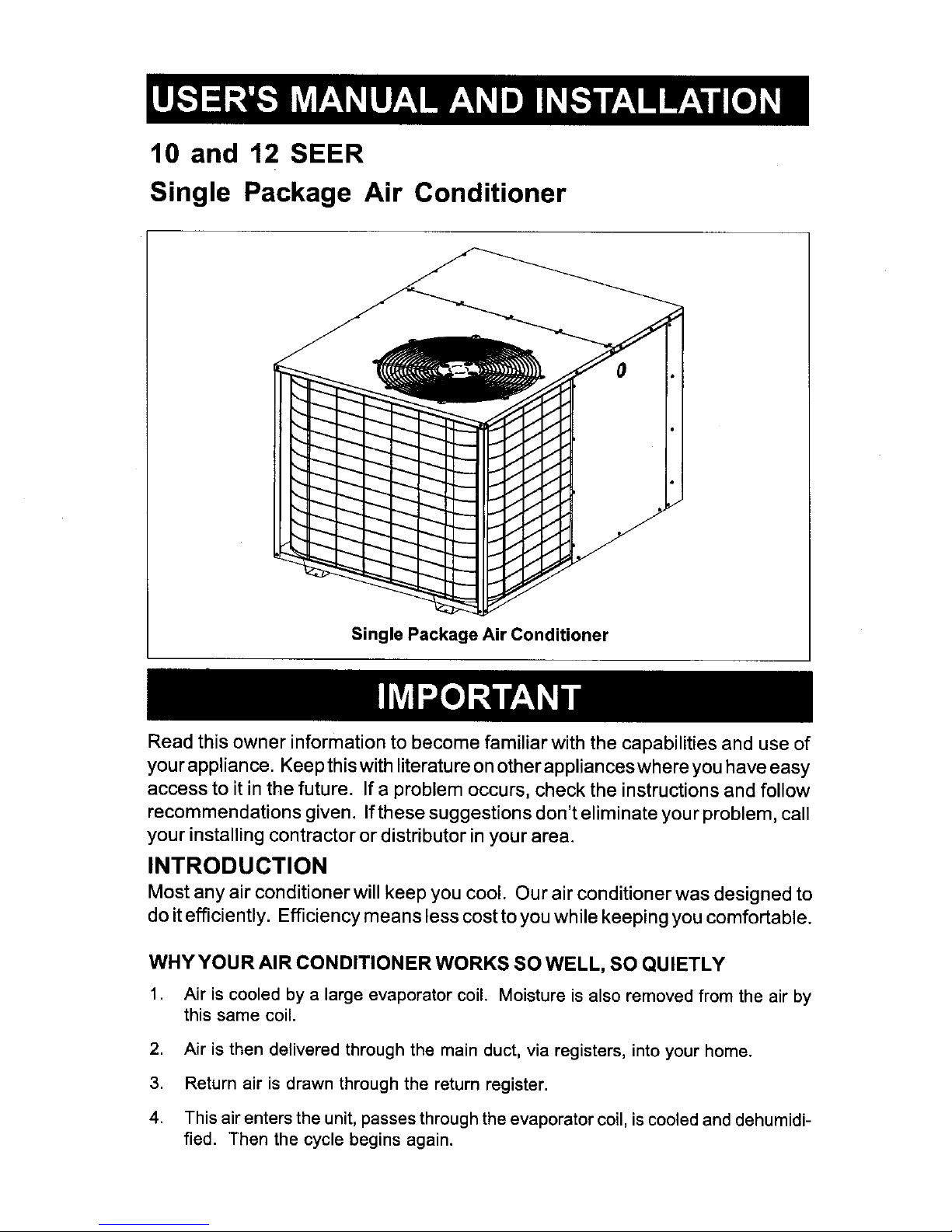
10 and 12 SEER
Single Package Air Conditioner
Single Package Air Conditioner
Read this owner information to become familiar with the capabilities and use of
your appliance. Keep this with literature on other appliances where you have easy
access to it in the future. If a problem occurs, check the instructions and follow
recommendations given. If these suggestions don't eliminate your problem, call
your installing contractor or distributor in your area.
INTRODUCTION
Most any air conditioner will keep you cool. Our air conditioner was designed to
do it efficiently. Efficiency means less cost to you while keeping you comfortable.
WHY YOUR AIR CONDITIONER WORKS SO WELL, SO QUIETLY
1. Air is cooled by a large evaporator coil. Moisture is also removed from the air by
this same coil.
2. Air is then delivered through the main duct, via registers, into your home.
3. Return air is drawn through the return register.
4. This air enters the unit, passes through the evaporator coil, is cooled and dehumidi-
fied. Then the cycle begins again.
SECTION t. OWNER INFORMATION
OPERATING INSTRUCTIONS
To Turn On Air Conditioner
If you have a heating/cooling thermostat:
1. Set the system switch to "Cool."
2. Set the thermostat at the temperature level
you desire.
3. Turn the power on. Your air conditioner
should start as soon as room temperature
rises above the setting on the thermostat.
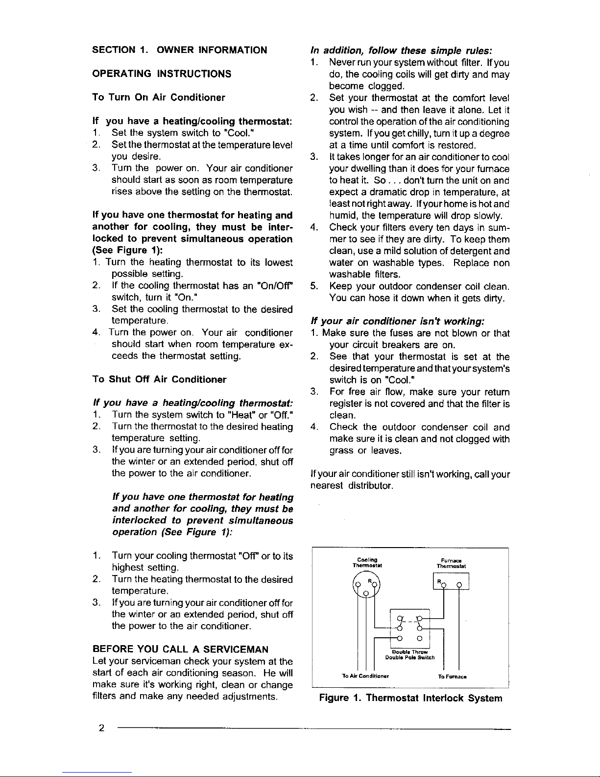
If you have one thermostat for heating and
another for cooling, they must be inter-
locked to prevent simultaneous operation
(See Figure 1):
1. Turn the heating thermostat to its lowest
possible setting.
2. If the cooling thermostat has an "On/Off"
switch, turn it "On."
3. Set the cooling thermostat to the desired
temperature.
4. Turn the power on. Your air conditioner
should start when room temperature ex-
ceeds the thermostat setting.
To Shut Off Air Conditioner
If you have a heating/cooling thermostat:
1. Turn the system switch to "Heat" or "Off."
2. Turn the thermostat to the desired heating
temperature setting.
3. If you are turning yourairconditionerofffor
the winter or an extended period, shut off
the power to the air conditioner.
If you have one thermostat for heating
and another for cooling, they must be
interlocked to prevent simultaneous
operation (See Figure I):
1. Turn your cooling thermostat "Off" or to its
highest setting.
2. Turn the heating thermostat to the desired
temperature.
3. If you are turning your air conditioner off for
the winter or aM extended period, shut off
the power to the air conditioner.
BEFORE YOU CALL A SERVICEMAN
Let your serviceman check your system at the
start of each air conditioning season. He will
make sure it'sworking right, clean or change
filters and make any needed adjustments.
In addition, follow these simple rules:
1. Never runyour system without filter. Ifyou
do, the coolingcoils will get dirty and may
become dogged.
2. Set your thermostat at the comfort level
you wish -- and then leave it alone. Let it
control the operation of the air conditioning
system. Ifyou get chilly, turn itup a degree
at a time until comfort is restored.
3. It takes longer for an air conditionerto cool
your dwelling than it does for your furnace
to heat it. So... don't turnthe uniton and
expect a dramatic drop in temperature, at
least notdght away. Ifyourhome ishotand
humid, the temperature will drop slowly.
4. Check your filters every ten days in sum-
mer to see if they are dirty. To keep them
clean, use a mild solutionofdetergent and
water on washable types. Replace non
washable filters.
5. Keep your outdoor condenser coil clean.
You can hose it down when it gets dirty.
If your air conditioner isn't working:
1. Make sure the fuses are not blown or that
your circuit breakers are on.
2. See that your thermostat is set at the
desired temperature andthat your system's
switch is on "Cool."
3. For free air flow, make sure your return
register is not covered and that the filter is
clean.
4. Check the outdoor condenser coil and
make sure it is clean and not clogged with
grass or leaves.
if your air conditioner still isn'tworking, call your
nearest distributor.
Cooling Furnace
Thermostat Thermos1
Double Throw
Double Po_ Switch
3"o Air Conditio TM To Furnace
Figure 1. Thermostat Interlock System
2
SECTION 2. INSTALLER
INFORMATION
GENERAL
Read the following instructions completely
before performing the installation,
These instructionsare for the use of qualified
personnel specially trained and experienced in
the installation of this type of equipment and
related system components. Some states re-
quire installation and service personnel to be
licensed. Unqualified individuals should not
attempt to interpret these instructions or install
this equipment.
The single packaged air conditioners are de-
signed for outdoor installationonly and can be
readily connected into the high static duct
system of a home. The only connections
needed for installation are the supply and return
ducts, the line voltage, and thermostat wiring.
A complete air conditioning system typically
consists of:
• Single Package Air Conditioner
• Home Fittings Kit
• Unit Fittings Kit
• Thermostat
The single package air conditioner is com-
pletely assembled, factory wired, and factory
run tested. The units are ready for easy and
immediate installation.
PRE-INSTALLATION CHECK
Before any installationis attempted, the cooling
load of the area to be conditioned must be
calculated and a system of the proper capacity
selected. Itis recommended that the area to be
conditioned be completely insulated and vapor
sealed.
The installer should comply with all local codes
and regulations which govern the installationof
this type of equipment. Local codes and
regulations take precedence over any recom-
mendations contained in these instructions.
Consult local building codes and the National
Electrical Code (ANSI Cl) for special installa-
tion requirements.
Inspecting Equipment: All units are securely
packed at the time of shipment and, upon
arrival, should be carefully inspected for dam-
age. Claims for damage (apparent or con-
cealed) should be filed immediately with the
carrier.
INSTALLATION
1. SELECT THE BEST LOCATION FOR
THE AIR CONDITIONING UNIT
IMPORTANT: DO NOT PLACE UNIT UNDER
THE HOME.
• Select a solid, level position, preferably on a
concrete slab, slightly above the grade level,
and parallel to the home.
• The hot condenser air must be discharged
up and away fi'om the home, and if possible,
in a direction with the prevailing wind.
• De not place the unit in a confined space.
• If practical, place the air conditioner where it
and the ducts will be shaded from the after-
noon sun when the heat load is greatest.
• Try to select a site for the unitthat is as close
as possible to the proposed return grille
location.
• Keep inmind that the length ofthe supply and
return ducts should be kept to a minimum with
no sharp radiused bends.
2. UNPACK THE UNIT
It is recommended that the unit be unpacked at
the installation site to minimize damage due to
handling.
CAUTION:
Do not tip the unit on its side. Oil may
enter the compressor cylinders and
cause starting trouble. If unit has been
set on its side, restore to upright posi-
tion and do not run for several hours.
Then run unit for a few seconds. Do
this three or four times with five min-
utes between runs.
The electrical supply should be checked to
determine if adequate power is available. If
there is any question concerning the power
supply, contact the local power company.
a. Remove the bands from around the unit.
b. Unfold the top and bottom cap flanges.
c. Carefully remove the top cap and tube.
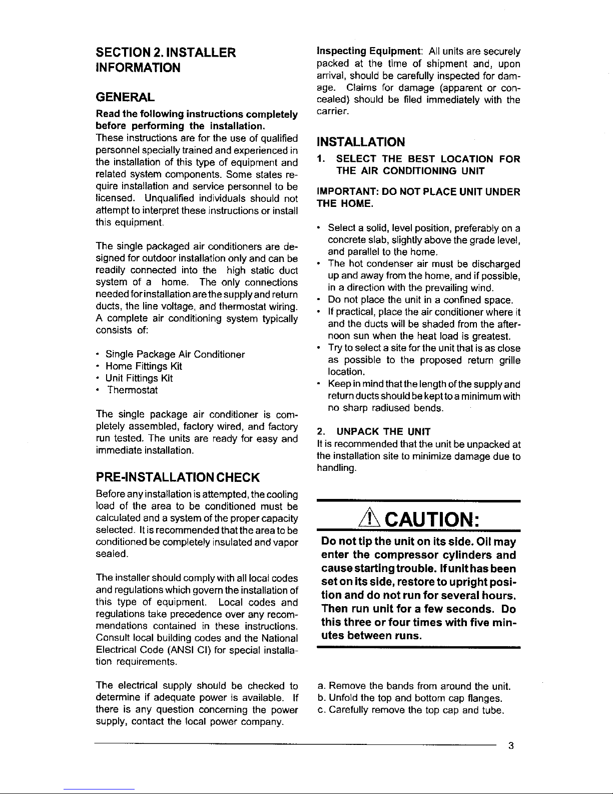
6ft.
Figure 2. Minimum Unit Clearances
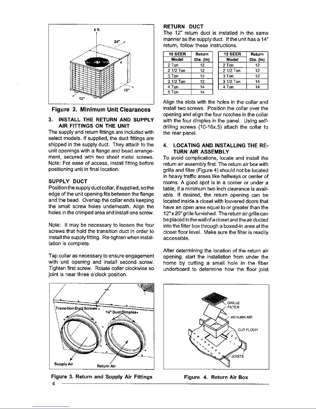
3. INSTALL THE RETURN AND SUPPLY
AIR FITTINGS ON THE UNIT
The supply and returnfittings are included with
select models. If supplied, the duct fittings are
shipped in the supply duct. They attach to the
unitopenings with a flange and bead arrange-
ment, secured with two sheet metal screws.
Note: For ease of access, install fitting before
positioningunitin final location.
SUPPLY DUCT
Positionthe supplyduct collar,ifsupplied,sothe
edge ofthe unitopening fitsbetween the flange
and the bead. Overlap the collar ends keeping
the small screw holes underneath. Align the
holes inthe crimped area and installone screw.
Note: It may be necessary to loosen the four
screws that hold the transition duct in order to
installthe supply fitting. Re-tighten when instal-
lation is complete.
Tap collar as necessary to ensure engagement
with unit opening and install second screw.
Tighten first screw. Rotate collar clockwise so
joint is near three o'clock position.
RETURN DUCT
The 12" return duct is installed in the same
manner as the supply duct. Ifthe unit has a 14"
return, follow these instructions.
10 SEER Return
Model eia. (in)
2 Ton 12
2 1/2 Ton 12
3 Ton 12
3 1/2 Ton 12
4 Ton 14
5 Ton 14
12 SEER Return
Model Dia. (in)
2 Ton 12
2 1/2 Ton 12
3 Ton 12
3 1/2 Ton 14
4 Ton 14
Align the slots with the holes in the collar and
install two screws. Position the collar over the
opening and align the four notches inthe collar
with the four dimples in the panel. Using self-
ddlling screws (10-16x.5) attach the collar to
the rear panel.
4. LOCATING AND INSTALLING THE RE-
TURN AIR ASSEMBLY
To avoid complications, locate and install the
return air assembly first. The return air box with
grille and filter (Figure 4) should not be located
in heavy traffic areas like hallways or center of
rooms. A good spot is in a corner or under a
table, if a minimum two inch clearance is avail-
able. If desired, the return opening can be
located inside a closet with Iouvered doors that
have an open area equal to or greater than the
12"x 20" grille furnished. The return airgrille can
be placed in the wall of acloset and the air ducted
into the filter box through a boxed-in area at the
closet floor level. Make sure the filter is readily
accessible.
After determining the location of the return air
opening, start the installation from under the
home by cutting a small hole in the fiber
underboard to determine hew the floor joist
:ILTER
CUT FLOOR
Supply Air Return Air
Figure 3. Return and Supply Air Fittings
4
Figure 4. Return Air Box
location will affect cutting the opening needed
for the box. Floor joists generally are located on
16" centers, leaving 14-3/8" between joists.
After measuring the return air box (approxi-
mately 12-1/4" x 14-1/4"), cut the hole through
the floor so that the box will fit between the floor
joists. Careshould betakenwhen cuttingthrough
carpeting to avoid snags. In most installations
it will be necessary to cut a similar hole in the
fiberboard directly under the hole in the floor.
However, if the floor is more than ten inches
deep, it will only be necessary to cut a hole for
the collar on the return air box orforthe insulated
duct.
Set the box into the opening and fasten with
screws or nails. Put the filter and return air grille
in place.
5. LOCATING AND INSTALLING THE
SUPPLY DAMPER(S)
CAUTION:
When a home is not equipped with a
make-ready kit means must be pro-
vided to prevent simultaneous opera-
tion of the heating and cooling units. A
heat/cool thermostat is available for
this purpose.
When installing this air conditioning
system in conjunction with a furnace,
a damper must be installed in the fur-
nace base assembly to prevent cold
air being discharged around the heat
exchanger. Damage to the heat ex-
changer and asphyxiation may occur
ifa damper is not installed.
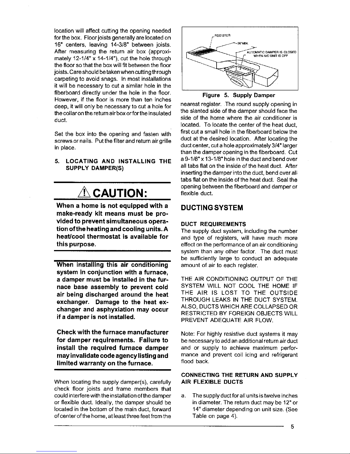
Figure 5. Supply Damper
nearest register. The round supply opening in
the slanted side of the damper should face the
side of the home where the air conditioner is
located. To locate the center of the heat duct,
first cut a small hole in the fiberboard below the
duct at the desired location. After locating the
duct center, cut a hole approximately 3/4" larger
than the damper opening in the fiberboard. Cut
a 9-1/8" x 13-1/8" hole in the duct and bend over
all tabs flat on the inside of the heat duct. After
inserting the damper into the duct, bend over all
tabs flat on the inside of the heat duct. Seal the
opening between the fiberboard and damper or
flexible duct.
DUCTINGSYSTEM
DUCT REQUIREMENTS
The supply duct system, including the number
and type of registers, will have much more
effect on the performance ofan air conditioning
system than any other factor. The duct must
be sufficiently large to conduct an adequate
amount of air to each register.
THE AIR CONDITIONING OUTPUT OF THE
SYSTEM WILL NOT COOL THE HOME IF
THE AiR IS LOST TO THE OUTSIDE
THROUGH LEAKS IN THE DUCT SYSTEM.
ALSO, DUCTS WHICH ARE COLLAPSED OR
RESTRICTED BY FOREIGN OBJECTS WILL
PREVENT ADEQUATE AIR FLOW.
Check with the furnace manufacturer
for damper requirements. Failure to
install the required furnace damper
may invalidate code agency listing and
limited warranty on the furnace.
When locating the supply damper(s), carefully
check floor joists and frame members that
could interferewith the installation ofthe damper
or flexible duct. Ideally, the damper should be
located in the bottom of the main duct, forward
ofcenter ofthe home, at least three feet from the
Note: For highly resistive duct systems it may
be necessary to add an additional return air duct
and or supply to achieve maximum perfor-
mance and prevent coil icing and refrigerant
flood back.
CONNECTING THE RETURN AND SUPPLY
AIR FLEXIBLE DUCTS
a.
The supply duct for all units istwelve inches
in diameter. The return duct may be 12" or
14" diameter depending on unit size. (See
Table on page 4).
5
 Loading...