

Nordyne O4MD, O4MD-091A-12-F, O4MD-140A-16-F Maintenance Manual

Installation, Operation and
Maintenance Manual
O4MD Oil Fired Downflow/
Horizontal Warm Air Furnace
FOR YOUR SAFETY:
Do not store or use gasoline or other flammable liquids or
vapors in the vicinity of this, or any other appliance.
ALL INSTALLATIONS MUST MEET ALL
LOCAL, PROVINCIAL/STATE, AND
FEDERAL CODES WHICH MAY
DIFFER FROM THIS MANUAL
Read this complete manual before beginning
installation. These instructions must be kept
with the furnace for future reference.
153B0801

2 153B0801
Table of Contents
1, Introduction .......................................................................................................................................................... 4
2, Heat Loss .............................................................................................................................................................. 4
3, Location of Unit ................................................................................................................................................... 4
4, Air Conditioning Applications ............................................................................................................................ 6
5, Combustion Air .................................................................................................................................................... 6
6, Chimney Venting ................................................................................................................................................. 7
7, Barometric Damper Control ............................................................................................................................... 7
8, Fan and Limit Control ......................................................................................................................................... 7
9, Electrical Connections ........................................................................................................................................ 8
10, Humidifier ........................................................................................................................................................... 8
11, Oil Piping Installation ........................................................................................................................................ 8
12, Oil Filter .............................................................................................................................................................. 9
13, Oil Burner Nozzles ............................................................................................................................................. 9
14, Combustion Chamber ........................................................................................................................................ 9
15, Burner Electrodes ............................................................................................................................................ 10
16, Oil Burner Primary Control ............................................................................................................................. 10
17, Oil Burner Set-Up ............................................................................................................................................ 10
18, Circulating Air Blower ..................................................................................................................................... 11
19, Initial Start Up .................................................................................................................................................. 12
20, Sequence of Operation ................................................................................................................................... 13
21, Final Check Out ............................................................................................................................................... 13
22, Operating Instructions .................................................................................................................................... 13
23, Maintenance and Service ................................................................................................................................ 13
Wiring Diagram: O4MD-091A-12-F Series Oil Furnace ...................................................................................... 21
Wiring Diagram: O4MD-140A-16-F Series Oil Furnace ...................................................................................... 22
Wiring Diagram: Continuous Low Speed Fan Operation Modification (Typical), Error! Bookmark not defined,
Wiring Diagram: Alternate Thermostat Wiring Methods ................................................................................... 24
Troubleshooting ..................................................................................................................................................... 25
Homeowner's reference guide .............................................................................................................................. 29
Memo to Installer .................................................................................................................................................... 29
3 153B0801
IMPORTANT:
SAVE THESE INSTRUCTIONS FOR FUTURE REFERENCE
1. INTRODUCTION
Please read these instructions completely and carefully
before installing and operating the furnace.
The furnace must be installed and set up by a qualified
contractor
MODEL O4MD-091A-12-F
Model O4MD-091A-12-F is an oil fired forced air multi-
positional furnace, with a nominal output capacity range
of 60,000 BTU/Hr. to 90,000 BTU/Hr. The O4MD-091A-
12-F furnace may be installed in the down-flow position,
as well as both horizontal positions.
MODEL O4M D-140A-16-F
Model O4MD-140A-16-F is an oil fired forced air multi-
positional furnace, with a nominal output capacity range
of 91,000 BTU/Hr. to 128,000 BTU/Hr. The O4MD-140A-
16-F furnace may be installed in the down-flow position,
as well as both horizontal positions.
The O4MD-091A-12-F model is CSA listed, (NRTL/C) for
use with No. 1 (Stove) and No. 2 (Furnace) Oil. Please
refer to the tables in Appendix A for performance and
dimensional data.
The Model O4MD-140A-16-F furnace is listed with the
Canadian Standards Association, (CSA), and the Energy
Testing Laboratory of Maine, (ETLM), for use with No. 1
(Stove) and No. 2 (Furnace) Oil. Please refer to the
tables in the appendix for performance and dimensional
data.
When installation or application questions arise,
regulations prescribed in the National Codes and Local
Regulations take precedence over the general
instructions provided with this installation manual. When
in doubt, please consult your local authorities.
All models are shipped assembled and pre-wired. The
furnace should be carefully inspected for damage when
being unpacked.
2. HEAT LOSS
The maximum hourly heat loss for each heated space
shall be calculated in accordance with the procedures
described in Manual J. titled, "Load Calculation"
published by the Air Conditioning Contractors of America,
or method suitable for local conditions or prescribed by
local codes. The calculation results obtained should be in
substantial agreement with, and not less than those
obtained using the procedure described in Manual J.
In Canada, the maximum hourly heat loss for each
heated space shall be calculated in accordance with the
procedures described in the manuals of the Heating,
Refrigeration and Air Conditioning Institute of Canada
(HRAI), or by method suitable for local conditions.
3. LOCATION OF UNIT
The furnace should be located such that the flue
connection to the chimney is short, direct and consists of
as few elbows as possible. When possible, the unit
should be centralized with respect to the supply and
return air ductwork. A central location minimizes the trunk
duct sizing. All models may be installed on combustible
floors.
I ,WARNINGI
DO NOT USE GASOLINE, CRANK CASE
OIL, OR ANY OIL CONTAINING GASOLINE.
The installation of the furnace and related equipment
shall be installed in accordance with the regulations of
NFPA No. 31, Installation of Oil Burnin,q Equipment, as
well as in accordance with local codes.
In Canada, the installation of the furnace and related
equipment shall be installed in accordance with the
regulations of CAN/CSA-B139, Installation Code For Oil
Burnin.q Equipment, as well as in accordance with local
codes.
Minimum installation clearances are listed in Table 2.
Sub-bases, for downflow installations are available for the
O4MD-091A-12-F and O4MD-140A-16-F series furnaces:
O4MD-091A-12-F: Order Part No. 29018.
O4MD-140A-16-F: Order Part No. 006000073.
4 153B0801
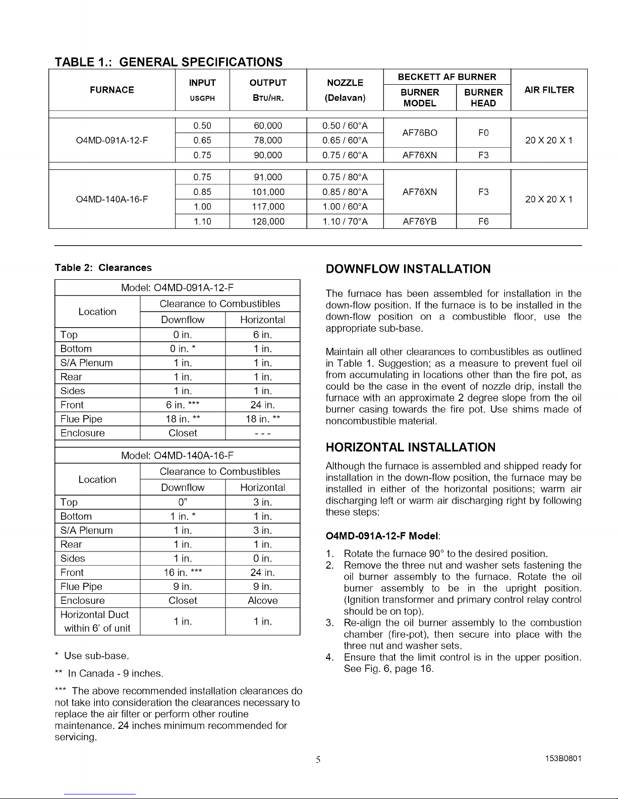
TABLE 1.: GENERAL SPECIFICATIONS
FURNACE
INPUT OUTPUT
USGPH BTU/HR.
NOZZLE
(Delavan)
BECKETT AF BURNER
BURNER
MODEL
BURNER
HEAD
AIR FILTER
0.50 60,000
O4MD-091A-12-F
O4MD-140A-16-F
0.65 78,000
0.75 90,000
0.75 91,000
0.85 101,000
1.00 117,000
1.10 128,000
Table 2: Clearances
Model: O4MD-091A-12-F
Clearance to Combustibles
Location
Top
Bottom
S/A Plenum
Rear
Sides
Front
Flue Pipe
Enclosure
Model:
Downflow
0 in.
0 in. *
1 in.
1 in.
1 in.
6 in. ***
18 in. **
Closet
O4MD-140A-16-F
Horizontal
6 in.
1 in.
1 in.
1 in.
1 in.
24 in.
18 in. **
Clearance to Combustibles
Location
Top
Bottom
S/A Plenum
Rear
Sides
Front
Flue Pipe
Enclosure
Horizontal Duct
within 6' of unit
Downflow
0"
1 in.*
1 in.
1 in.
1 in.
16 in. ***
9 in.
Closet
1 in. 1 in.
Horizontal
3 in.
1 in.
3 in.
1 in.
0 in.
24 in.
9 in.
Alcove
* Use sub-base.
** In Canada - 9 inches.
*** The above recommended installation clearances do
not take into consideration the clearances necessary to
replace the air filter or perform other routine
maintenance. 24 inches minimum recommended for
servicing.
0.50 / 60°A
0.65 / 60°A
0.75 / 60°A
0.75 / 80°A
0.85 / 80°A
1.00 / 60°A
1.10 / 70°A
AF76BO
AF76XN
AF76XN F3
AF76YB F6
F0
F3
20X20X1
20X20X1
DOWNFLOW INSTALLATION
The furnace has been assembled for installation in the
down-flow position. If the furnace is to be installed in the
down-flow position on a combustible floor, use the
appropriate sub-base.
Maintain all other clearances to combustibles as outlined
in Table 1. Suggestion; as a measure to prevent fuel oil
from accumulating in locations other than the fire pot, as
could be the case in the event of nozzle drip, install the
furnace with an approximate 2 degree slope from the oil
burner casing towards the fire pot. Use shims made of
noncombustible material.
HORIZONTAL INSTALLATION
Although the furnace is assembled and shipped ready for
installation in the down-flow position, the furnace may be
installed in either of the horizontal positions; warm air
discharging left or warm air discharging right by following
these steps:
O4MD-091A-12-F Model:
1. Rotate the furnace 90° to the desired position.
2. Remove the three nut and washer sets fastening the
oil burner assembly to the furnace. Rotate the oil
burner assembly to be in the upright position.
(Ignition transformer and primary control relay control
should be on top).
3. Re-align the oil burner assembly to the combustion
chamber (fire-pot), then secure into place with the
three nut and washer sets.
4. Ensure that the limit control is in the upper position.
See Fig. 6, page 16.
5 153B0801
O4M D-140A-16-F Model:
,
Rotate the furnace 90°to the desired position.
2. Remove the three nut and washer sets fastening the
oil burner assembly to the furnace. Rotate the oil
burner assembly to be in the upright position.
(Ignition transformer and primary control relay control
should be on top).
3. Re-align the oil burner assembly to the combustion
chamber (fire-pot), then secure into place with the
three nut and washer sets.
4. Remove the cover from the flue collar.
5. Remove the screws securing the flue collar to the
furnace, then rotate the flue collar 90°, such that the
venting attaches to the top.
6. Secure the flue collar to the furnace, then reinstall the
flue collar cover.
NON-SUSPENDED INSTALLATION
Maintain clearances to combustibles as outlined in Table
1. Installation on a combustible floor requires a clearance
of 1 inch. This can be done by using noncombustible
materials such as one inch thick channel iron or similar
material. The furnace must be supported in such a way
as to not allow twisting or sagging of the cabinet.
Suggestion; as a measure to prevent fuel oil from
accumulating in locations other than the fire pot, as could
be the case in the event of nozzle drip, install the furnace
with an approximate 2 degree slope from the oil burner
casing towards the fire pot. Use shims made of
noncombustible material.
shown in Figure 4, page 15. The furnace must be
supported in such a way as to not allow twisting or
sagging of the cabinet. Suggestion; as a measure to
prevent fuel oil from accumulating in locations other than
the fire pot, as could be the case in the event of nozzle
drip, install the furnace with an approximate 2 degree
slope from the oil burner casing towards the fire pot.
4. AIR CONDITIONING APPLICATIONS
If the furnace is used in conjunction with air conditioning,
the furnace shall be installed in parallel with or upstream
from the evaporator coil to avoid condensation in the heat
exchanger. In a parallel installation, the dampers or air
controlling means must prevent chilled air from entering
the furnace. If the dampers are manually operated, there
must be a means of control to prevent the operation of
either system unless the dampers are in the full heat or
full cool position. The air heated by the furnace shall not
pass through a refrigeration unit unless the unit is
specifically approved for such service.
IMPORTANT: DO NOT INSTALL AN AIR
CONDITIONING EVAPORATOR COIL IN THE RETURN
AIR PLENUM.
The blower speed must be checked and adjusted to
compensate for the pressure drop caused by the
evaporator coil. Refer to Appendix B for recommended
wiring and electrical connections of the air conditioning
controls.
5. COMBUSTION AIR
SUSPENDED INSTALLATION
O4MD-091A-12-F: Maintain clearances to combustibles
as outlined in Table 1. The recommended method to
suspend the furnace is to fabricate a cradle with angle
iron, 2" slotted angle, or steel channel and 318" threaded
rod. The threaded rod should be located external to the
furnace. The furnace must be supported in such a way as
to not allow twisting or sagging of the cabinet. Position
the cradle so as to not interfere with accessing the burner
and blower compartments. Suggestion; as a measure to
prevent fuel oil from accumulating in locations other than
the fire pot, as could be the case in the event of nozzle
drip, install the furnace with an approximate 2 degree
slope from the oil burner casing towards the fire pot.
O4MD-140A-16-F: Maintain clearances to combustibles
as outlined in Table 1. Remove the four circular knock-
outs on the top panel, and similarly, the four circular
knock-outs on the bottom panel. The removed knock-
outs allow 3/8 inch treaded road to be inserted through
the interior of the furnace. Use care when inserting rods,
since the foil backed insulation can be easily ripped and
torn away from the panel surfaces. Secure the furnace
with 2 inch minimum slotted angle or equivalent, as
If the furnace is installed in a closet or utility room, two
openings must be provided connecting to a well-
ventilated space (full basement, living room or other room
opening thereto, but not a bedroom or bathroom). One
opening shall be located above the level of the upper vent
opening and one opening below the combustion air inlet
opening in the front of the furnace. Each opening shall
have a minimum free area of 1½ square inches per 1,000
Btu/h of total input rating of all appliances installed in the
room.
For furnaces located in buildings of unusually tight
construction, such as those with high quality weather
stripping, caulking, windows and doors, or storm sashed
windows, or where basement windows are well sealed, a
permanent opening communicating with a well ventilated
attic or with the outdoors shall be provided, using a duct if
necessary. The duct opening shall have a free area of 1½
square inches per 1,000 Btu/h of total input rating of all
appliances to be installed. When a furnace is installed in
a full basement, infiltration is normally adequate to
provide air for combustion and draft operation. Furnace
rooms under 700 ft3 (65m 3) should automatically be
treated as confined space.
6 153B0801
The Model CAS-2B-90E Furnace Boot manufactured by
Field Controls, Inc. may be used with the furnace to
obtain combustion air directly from outdoors. Use of this
device does not alter the need for ventilation air;
however, it does provide a good direct source of
combustion air and is connected directly to the oil burner.
6. CHIMNEY VENTING
The flue pipe should be as short as possible with
horizontal pipes sloping upward toward the chimney at a
rate of one-quarter inch to the foot. The flue pipe should
not be smaller in cross sectional area than the flue collar
on the furnace. The flue pipe should connect to the
chimney such that the flue pipe extends into, and
terminates flush with the inside surface of the chimney
liner. Seal the joint between the pipe and the lining. The
chimney outlet should be at least two feet above the
highest point of a peaked roof. All unused chimney
openings should be closed. Chimneys must conform to
local, provincial or state codes, or in the absence of local
regulations, to the requirements of the National Building
Code.
NOTE: THE FURNACE IS APPROVED FOR USE WITH
L-VENT.
IAcAuTION I
THE FURNACE MUST BE CONNECTED TO A FLUE
HAVING SUFFICIENT DRAFT AT ALL TIMES TO
ENSURE SAFE AND PROPER OPERATION OF THE
APPLIANCE.
The flue pipe must not pass through any floor or ceiling,
but may pass through a wall where suitable fire protection
provisions have been installed. Refer to the latest edition
of NFPA 31 for regulations governing the installation of oil
burning equipment. In Canada, refer to the latest edition
of CAN/CSA B-139 for rules governing the installation of
oil burning equipment.
7. BAROMETRIC DAMPER CONTROL
8. FAN AND LIMIT CONTROL
The L4064W fan / limit control is a thermally activated
control. There are two active components to the control.
The "fan on" function is actuated by a heater wrapped
bimetallic lever. The internal heater coil is activated
whenever the oil burner is operating, resulting in the start
up of the blower motor within 30 seconds of the ignition
cycle. This is a non-adjustable setting. The second
component is a helical bi-metal sensing element
enclosed in a metal guard. This controls the "fan off"
function and high limit cut off function. This control
provides a delay between the burner ignition and blower
start-up to eliminate excessive flow of cold air when the
blower activates. Blower shutdown is also delayed to
remove any residual heat from the heat exchanger and
improve the annual efficiency of the furnace. "Fan off"
settings of 90° F to 100° F (32° C to 37°C) will usually be
satisfactory. In a normal cycle, the "fan on" adjustment
has little if any effect on the L4064W model control. If the
blower starts for brief periods after a burner cycle, the
condition can usually be eliminated by increasing the
differential between the "fan on" and "fan off" settings.
If after 1 minute, the blower has not come on, inspection
and / or repair of the fan / limit control wiring, or
replacement of the fan / limit control may be necessary.
The limit switch performs a safety function and breaks
power to the oil burner primary control, which shuts off
the burner if the furnace over-heats. The limit control is
thermally operated and automatically resets. The limit
control is factory installed, pre-set and is not adjustable.
Limit setting for O4MD-091A-12-F: 250°F. Limit Setting
for O4MD-140A-16-F: 220°F.
I' cAUTION I
FAN/LIMIT CONTROL LOCATION IS CRITICAL IN
THE O4MD-091A-12-F HORIZONTAL POSITIONS.
TO OPERATE EFFECTIVELY AS A HIGH LIMIT
CONTROL, THE CONTROL MUST BE INSTALLED
IN THE UPPER POSITION. See Figure 6, page 16.
This device is used in conjunction with conventional
chimney venting. This control (or draft regulator)
automatically maintains a constant negative pressure in
the furnace to obtain maximum efficiency. It ensures that
proper pressures are not exceeded. If the chimney does
not develop sufficient draft, the draft control cannot
function properly. The draft regulator, must be installed
within the same room or enclosure as the furnace, and
should not interfere with the combustion air supply to the
burner. The control should normally be located a
minimum of 3 pipe diameters from the furnace breeching
and installed in accordance to the instructions supplied
with the regulator. The flue outlet pressure (measured
between the furnace and draft regulator) should be set to
- 0.02 in. w.c.
The limit control and fan control are incorporated in the
same housing and are operated by the same thermal
element. Ensure, prior to installation, that the fan / limit
probe is not in contact with the heat exchanger.
The O4MD-091A-12-F Series furnace is equipped with a
160°F auxiliary limit control located in the blower
compartment.
The O4MD-140A-16-F Series furnace is equipped with
two auxiliary limit controls that are both automatic reset
types. One is a 200°F disc limit located behind the
junction box cover. The other is a 130°F. disc limit
located on the blower fan housing.
7 153B0801
IMPORTANT: THE O4MD-140A-16-F AUXILLIARY
LIMIT (200°F.) POSITIONING IS IMPORTANT. THE
DISC SIDE FACES THE HEAT EXCHANGER.
where the thermostat will be exposed to cold drafts, heat
from nearby lamps and appliances, exposure to sunlight,
heat from inside wall warm air stacks, etc.
9. ELECTRICAL CONNECTIONS
The O4MD-091A-12-F furnace is listed by the Canadian
Standards Association under the NRTL (North American)
Standard.
The O4MD-140A-16-F furnace is listed by the Canadian
Standards Association (CSA) and by the Energy Testing
Laboratory of Maine (ETLM).
Both models are factory wired and require minimal field
wiring. In the United States, the wiring must be in
accordance with the National Fire Protection Association
NFPA-70, National Electrical Code, and with local codes
and regulations. In Canada, all field wiring should
conform to CAN/CSA C22.1 Canadian Electrical Code,
Part 1, and by local codes, where they prevail.
The furnace should be wired to a separate and dedicated
circuit in the main electrical panel; however, accessory
equipment such as electronic air cleaners and humidifiers
may be included on the furnace circuit. Although a
suitably located circuit breaker can be used as a service
switch, a separate service switch is advisable. The
service switch is necessary if reaching the circuit breaker
involves becoming close to the furnace, or if the furnace
is located between the circuit breaker and the means of
entry to the furnace room. The furnace switch (service
switch) should be clearly marked, installed in an easily
accessible area between the furnace and furnace room
entry, and be located in such a manner to reduce the
likelihood that it would be mistaken as a light switch or
similar device.
For thermostats with heat anticipators, the heat
anticipator should be adjusted to the amperage draw of
the heating control circuit as measured between the "R"
and "W" terminals of the thermostat. To reduce the risk
of damaging the heat anticipator, do not measure this
current with the thermostat connected to the circuit. To
determine the heating circuit amperage draw:
1. Note and disconnect the wires from the "R" and "W"
thermostat terminals.
2. Connect an ammeter between the two disconnected
wires from the thermostat.
3. Note the amperage reading.
4. Re-connect the thermostat wires. If the thermostat is
serving a combination heating and air conditioning
system, pay particular attention to polarity.
5. When the thermostat is reconnected and re-
plumbed, adjust the heat anticipator setting to match
the observed amperage reading.
10. HUMIDIFIER
A humidifier is an optional accessory available through
most heating supplies outlets. Installation should be
carried out in accordance with the humidifier
manufacturer's installation instructions. Water or water
droplets from the humidifier should not be allowed to
come into contact with the furnace heat exchanger. Do
not use direct drive motor connections as a source of
power for 120 VAC humidifiers and humidifier
transformers.
11. OIL PIPING INSTALLATION
The power requirement for all models is: 120 VAC, single
phase, 60 Hz., 12A.
Accessories requiring 120 VAC power sources such as
electronic air cleaners and humidifier transformers may
be powered from the furnace circuit, but should have
their own controls. Do not use the direct drive motor
connections as a power source, since there is a high risk
of damaging the accessories by exposure to high voltage
from the auto-generating windings of the direct drive
motor.
Thermostat wiring connections and air conditioning
contactor low voltage connections are shown in the wiring
diagrams. Some micro-electronic thermostats require
additional controls and wiring. Refer to the thermostat
manufacturer's instructions.
The thermostat should be located approximately 5 feet
above the floor, on an inside wall where there is good
natural air circulation, and where the thermostat will be
exposed to average room temperatures. Avoid locations
The entire fuel system should be installed in accordance
with the requirement of NFPA No. 31 and local codes and
regulations.
In Canada, the entire fuel system should be installed in
accordance with the requirements of CAN/CSA B-139,
and local regulations. Use only approved fuel oil tanks
piping, fittings and oil filters.
Ensure that all fittings used in a copper oil line system are
high quality flare fittings. Do not use compression fittinqs.
Do not use Teflon tape on any oil line fittings.
Pressurized or gravity feed installations must not exceed
10 PSIG on the inlet line or the return line at the pump. A
pressure greater than 10 PSIG may cause damage to the
shaft seal. A pressure-regulating device approved for use
with oil piping systems should be used if the height of the
fuel oil exceeds 11½ feet above the oil burner.
8 153B0801
The furnace may be installed with a one-pipe system with
gravity feed or lift. The maximum allowable lift on a single
line system is 8 feet. Lift should be measured from the
bottom (outlet) of the tank, to the inlet of the burner.
Sizing a single line system is complex because of the
difficulty estimating the pressure drop through each
fitting, bend and component in the line. In general, keep
single line systems short as possible. If the furnace is to
be installed in a suspended position, a two-pipe system
may be the better alternative. 2-stage oil pumps may be
used with both single line and two line systems. 2-stage
pumps are available from your HVAC wholesaler. The
following chart shows the allowable line lengths
(horizontal + vertical) for single and two stage oil pumps.
All distances are in feet.
Copper Tubing Oil Line Lengths
Single Stage 2-Stage
Lift _" O.U. O" O.U. _" O.U. O" O.U.
Tubing Tubing Tubing Tubing
0 53 100 68 100
1 49 100 65 100
2 45 100 63 100
3 41 100 60 100
4 37 100 58 100
5 33 100 55 100
6 29 100 53 100
7 25 99 50 100
8 21 83 48 100
9 17 68 45 100
10 13 52 42 100
12 ...... 37 100
14 ...... 32 100
16 ...... 27 100
18 ...... 22 88
In retrofit applications, where an existing oil line system is
in place, a vacuum check will help determine whether a
2-stage oil pump is necessary. The vacuum in a system
featuring a single stage oil pump should not exceed 6"
Hg. The vacuum in a system featuring a 2-stage oil pump
should not exceed 15" Hg. (inches of mercury).
NOTE: Two-pipe oil line systems require the installation
of the bypass plug in the oil pump. Consult pump
manufacturer's instructions
For additional information, see the installation information
sheet affixed to the oil burner.
12. OIL FILTER
All fuel systems should include an oil filter between the
fuel oil storage tank and the oil burner. For best results,
install the oil filter as close to the burner as possible.
When using an oil burner nozzle smaller than 0.65 U.S.
gallons per hour, install an additional 7 to 10 micron filter
as close as possible to the oil burner. For further details
of the oil supply tank and piping requirements, please
refer to the instructions and illustrations in the oil burner
and oil pump instructions shipped with the furnace.
13. OIL BURNER NOZZLES
The O4MD-091A-12-F furnace is certified for multiple
firing rates, ranging nominally from 60,000 to 90,000
Btu/hr.
The O4MD-140A-16-F furnace is certified for multiple
firing rates, ranging nominally from 90,000 to 130,000
BTU/hr. By manipulating the oil burner nozzle, flame
retention head, and temperature rise, the furnace may be
fired at an ideal rate for a wide range of structures.
Note: A conversion kit, Part No. 36000069 is available to
convert the O4MD-091A-12-F, 60 - 80 MBH model to the
O4MD-091A-12-F, 90 MBH model. The O4MD-091A-12-
F 90 MBH kit includes the 0.75 USGPH nozzle, 23/4-inch
static plate and F3 burner head.
Note: A conversion kit, Part No. 00600050 is available to
convert the O4MD-140A-16-F 90 -120 MBH to an
O4MD-140A-16-F 130 MBH. The O4MD-140A-16-F 130
MBH kit includes the 1.10 USGPH nozzle and F6 burner
head.
MODEL NOZZLE HEAD
O4MD-091A-12-F (060) 0.50 / 60°A F0
O4MD-091A-12-F (080) 0.65 / 60°A F0
O4MD-091A-12-F (090) 0.75 / 60°A F3
O4MD-140A-16-F (090) 0.75 / 80° A F3
O4MD-140A-16-F (100) 0.85 / 80° A F3
O4MD-140A-16-F (120) 1.00 / 60° A F3
O4MD-140A-16-F (130) 1.10 / 70° A F6
14. COMBUSTION CHAMBER
This furnace is equipped with an efficient cerafelt
combustion chamber. It is held in place by a retaining
bracket. Check the alignment of the combustion chamber
before firing. It is possible for the combustion chamber to
shift if subjected to rough handling during transit.
The cerafelt combustion chamber is quite soft initially.
After firing, it becomes very brittle. Be sure to do all
9 153B0801
 Loading...