

Nordyne MS3BA030KA, MS3BA042KA, MS3BA036KA, MS3BA024KA, MS3BA048KA Installation Instructions Manual
...
Outdoor Air Conditioner
10 SEER Standard Efficiency Split System
These instructions are primarily intended to assist qualified individuals experienced in the proper
installation of heating and/or air conditioning appliances. Some local codes require licensed
installation/service personnel for this type of equipment. Read all instructions carefully before
starting the installation.
These units have been designed and tested for
capacity and efficiency in accordance with ARI
Standards. Split System Air Conditioning units
are designed for use with awide variety of fossil
fuel furnaces, electric furnaces, air handlers,
and evaporator coil combinations.
USER'S iNFORMATiON
.
Set the thermostat temperature to the
desired temperature level by using the
temperature selector. Please refer to the
separate detailed user's manual for
complete thermostat programming
instructions. The furnace and indoor blower
will cycle on and off to maintain the indoor
temperature at the desired heating level.
Read this owner information to become familiar
with the capabilities and use of your appliance.
Keep this with literature on other appliances
where you have easy access to it in the future. If
a problem occurs, check the instructions and
follow recommendations given. If these
suggestions don't eliminate your problem, call
your servicing contractor.
OPERATING iNSTRUCTiONS
To Operate Your Air Conditioner
for Cooling m
I. Set the thermostat system switch to COOL
or AUTO and the thermostat fan switch to
AUTO. (See Figure I)
2. Set the thermostat temperature to the
desired temperature level by using the
temperature selector. Please refer to the
separate detailed thermostat user's manual
for complete instructions regarding
thermostat programming. The outdoor
unit and indoor blower will both cycle on
and off to maintain the indoor temperature
at the desired cooling level.
To Operate Your Furnace
for Heating
1. Set the thermostat system switch to HEAT
or AUTO and the thermostat fan switch to
AUTO. (See Figure I)
To Shut OffYour Air Conditioner
Set the thermostat system switch to OFF and the
thermostat fan switch to AUTO. (See Figure I)
The system will not operate, regardless of the
thermostat temperature setting.
To Operate the Indoor Blower
Continuously
Set the thermostat fan switch to ON (See Figure I )
The indoor blower will start immediately, and will
run continually until the fan switch is reset to
AUTO.
The continuous indoor blower operation can
be obtained with the thermostat system switch
set in any position, including OFF.
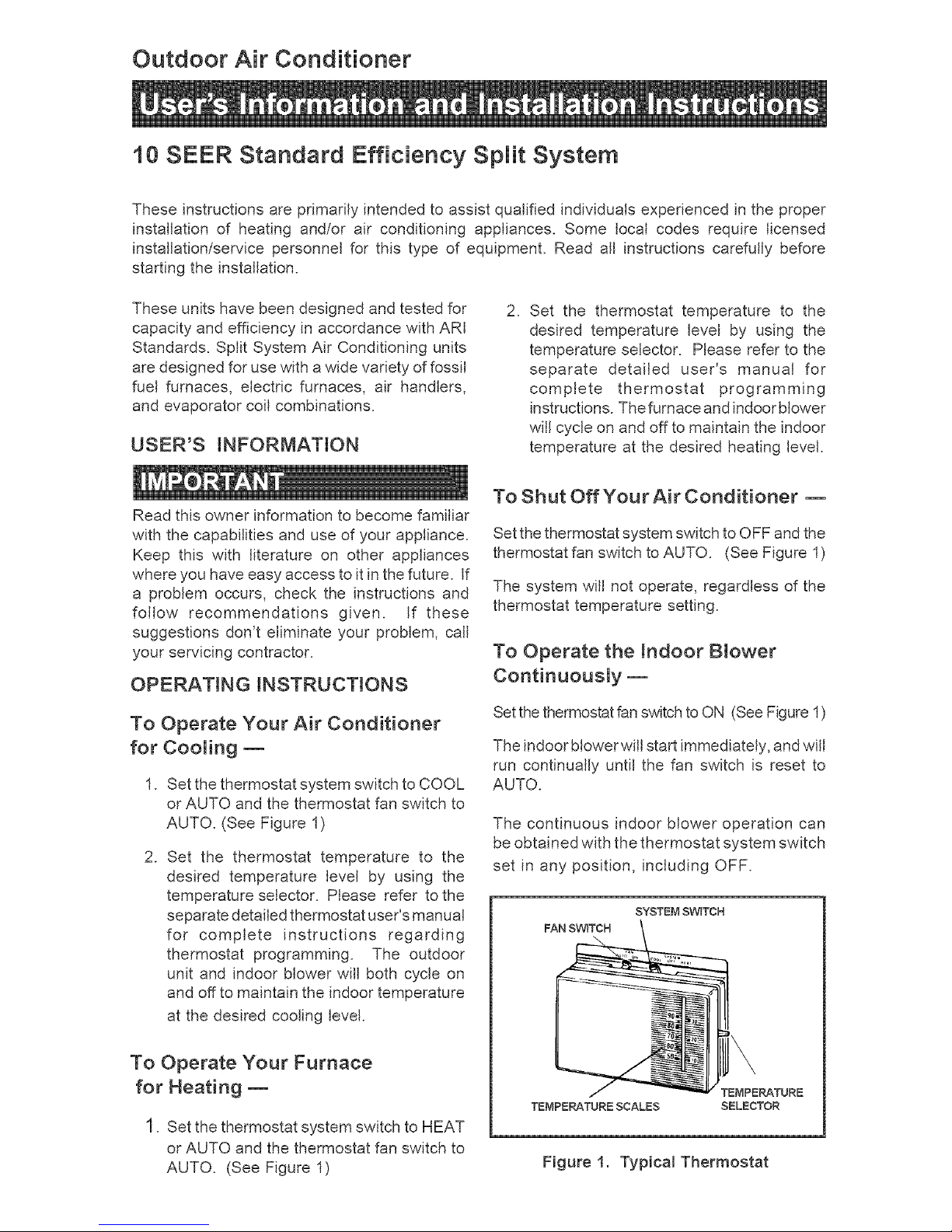
SYSTEMSWITCH
FAN SWITCH
Figure 1. Typical Thermostat
The continuousindoorbloweroperationis
typicallyusedtocirculatetheindoorairtoequalize
a temperatureunbalancedueto a sun load,
cooking,orfireplaceoperation.
To Maintain Your Air Conditioner--
Read Your Warranty
Please read the separate warranty document
completely. It contains valuable information
about your system.
1. GENERAL iNFORMATiON
Read the following instructions completely before
performing the installation.
Condensing Unit Section -- Each condensing
unit is shipped with a refrigerant charge adequate
to operate the outdoor section with an indoor
matching coil or air handler and 15 feet of
refrigeration line.
NOTE: DO NOT USE ANY PORTION OF THE
CHARGE FOR PURGING OR LEAK TESTING.
Liquid and Suction Lines-- Refrigerant grade
copper tubing should be used when installing
the system. Refrigerant suction line tubing
should be fully insulated to prevent condensate
damage.
Field Connections for Electdca_ Power Supply
-- All wiring must comply with the current
provisionsofthe"National Electrical Code" (ANSI
CI.) and with applicable local codes having
jurisdiction. Size of electrical conductors and
circuit protection must be in compliance with the
information listed on the outdoor unit data label.
2. SAFETY CONSiDERATiONS
Pressures Within the System -- Split System
Air Conditioning equipment contains liquid and
gaseous refrigerant under pressure. Installation
and servicing of this equipment should be
accomplished by qualified, trained personnel
thoroughly familiar with this type of equipment.
Under no circumstances should the homeowner
attempt to install and/or service the equipment
without proper supervision from trained and
qualified service personnel.
WARNmNG'.
Ensure aH emectricam power to the unit is
off prior to installing or servicing the
equipment. Failure to do so may cause
personal injury or death.
Be certain the emectricam power to the
outdoor u nit and the furnace/air handier
is disconnected before doing the
following recommended maintenance.
1. Regulady:
a. Clean or replace the indoor air filter at the
start of each heating and cooling season,
and when an accumulation of dust and dirt
is visible on the air filter.
b. Remove any leaves and grass clippings
from the coil in the outdoor unit, being
careful not to damage the aluminum fins.
c. Check for any obstruction, such as twigs,
sticks, etc.
Do not over-oil, or oil motors not factory-
equipped with oil tubes. The compressor
is hermetically "sealed" and does not
require lubrication.
2. Before Each Cooling Season:
If the furnace/air handler blower motor and
the outdoor unit fan motor(s) have oil tubes
at the motor bearings, apply 10 drops of
SAE No. 20 motor oil to each oil tube.
3. Before Calling a Service Technician, Be
Certain:
a. The unit thermostat is properly set -- see
"To Operate Your Air Conditioner for
Cooling" and "To Operate Your Furnace
for Heating."
b. The unit disconnect fuses are in good
condition, and
the electrical power to the unit is turned on.

Labels,Tags,Precautions-- Whenworking
withthis equipment,followall precautionsin
literature,ontags,andon labelsprovidedwith
theequipment.ReadandthorougNyunderstand
the instructionsprovidedwith the equipment
priortoperformingtheinstallationandoperational
checkoutoftheequipment.
CantileverMount -- The cantilevermount
shouldbedesignedwithadequatesafetyfactor
tosupporttheweightoftheequipment,andfor
loadsthemountissubjectedtoduringoperation.
installed equipmentshould be adequately
securedto the cantilevermountand levelled
priortooperationof theequipment.
3. SiTE PREPARATION
Unpacking Equipment- Remove the
cardboard carton and Literature Package from
the equipment.
inspect for Damage -- inspect the equipment
for damage prior to installing the equipment at
the job site. Ensure coil fins are straight and, if
necessary, comb fins to remove flattened and
bent fins.
Preferred Location of the Outdoor Unit at
the Job Site -- Conduct a survey of the job
site to determine the optimum location for
mounting the outdoor unit. Overhead
obstructions, poorly ventilated areas, and
areas subject to accumulation of debris should
be avoided. The outdoor unit must be installed
in such a manner that airflow through the coil is
not obstructed and that the unit can be serviced.
Facility Prerequisites -- Electrical power
supplied must be adequate for proper operation
of the equipment. The system must be wired and
provided with circuit protection in accordance
with local building codes and the National
Electrical Code.
Minimum Circuit Ampacity-- Electrical wiring
to the equipment must be compatible and in
compliance with the minimum circuit ampacity
listed on the outdoor unit data label.
Maximum Fuse/Circuit Breaker Size-- Circuit
protection for the outdoor unit must be compatible
with the maximum fuse/circuit breaker size listed
on the outdoor unit data label.
4. _NSTALLING THE OUTDOOR UNiT
Slab Mount -- The site selected for a slab
mount installation requires a stable foundation
and one not subject to erosion. The slab should
be level and anchored (if necessary) prior to
placing the equipment on the slab.
Roof Mount --The method of mounting should
be designed so as not to overload roof structures
nor transmit noise to the interior of the structure.
Refrigerant and electrical lines should be routed
through suitably waterproofed openings to
prevent water leaking into the structure.
5. NSTALMNG THE NDOOR UNIT
The indoor section of the unit should be installed
before proceeding with the routing of refrigerant
piping. Consult the Installation instructions of
the indoor unit (i.e., air handier, fan coil unit,
etc.) for details regarding installation.
6. CONNECTING REFRIGERANT
TUBING BETWEEN THE _NDOOR
AND OUTDOOR UNiT
Generam information -- Once the outdoor and
indoor unit placement has been determined,
route the refrigerant tubing between the
equipment in accordance with sound installation
practices. Refrigerant tubing should be routed
in a manner that minimizes the length of tubing
and the number of bends in the tubing.
Refrigerant tubing should be supported in a
manner that the tubing will not vibrate or abrade
during system operation. Tubing should be kept
clean of foreign debris during installation and
installation of a liquid line filter drier is
recommended if cleanliness or adequacy of
system evacuation isunknown or compromised.
Every effort should be made by the installer to
ensure that the field installed refrigerant
containing components of the system have been
installed in accordance with these instructions
and sound installation practices so as to insure
reliable system operation and longevity. The
maximum recommended interconnecting
refrigerant line length is 75 feet, and the vertical
elevation difference between the indoor and
outdoor sections should not exceed 20 feet.
Optiona! Equipment -- Optional equipment
(i.e.: filter/driers, liquid line solenoid valves, etc.)
should be installed in strict accordance with the
manufacturer's Installation Instructions.
 Loading...