

Nordyne MGHA, MMHA Installation Instructions Manual
Gas Furnaces - Blower & Relay
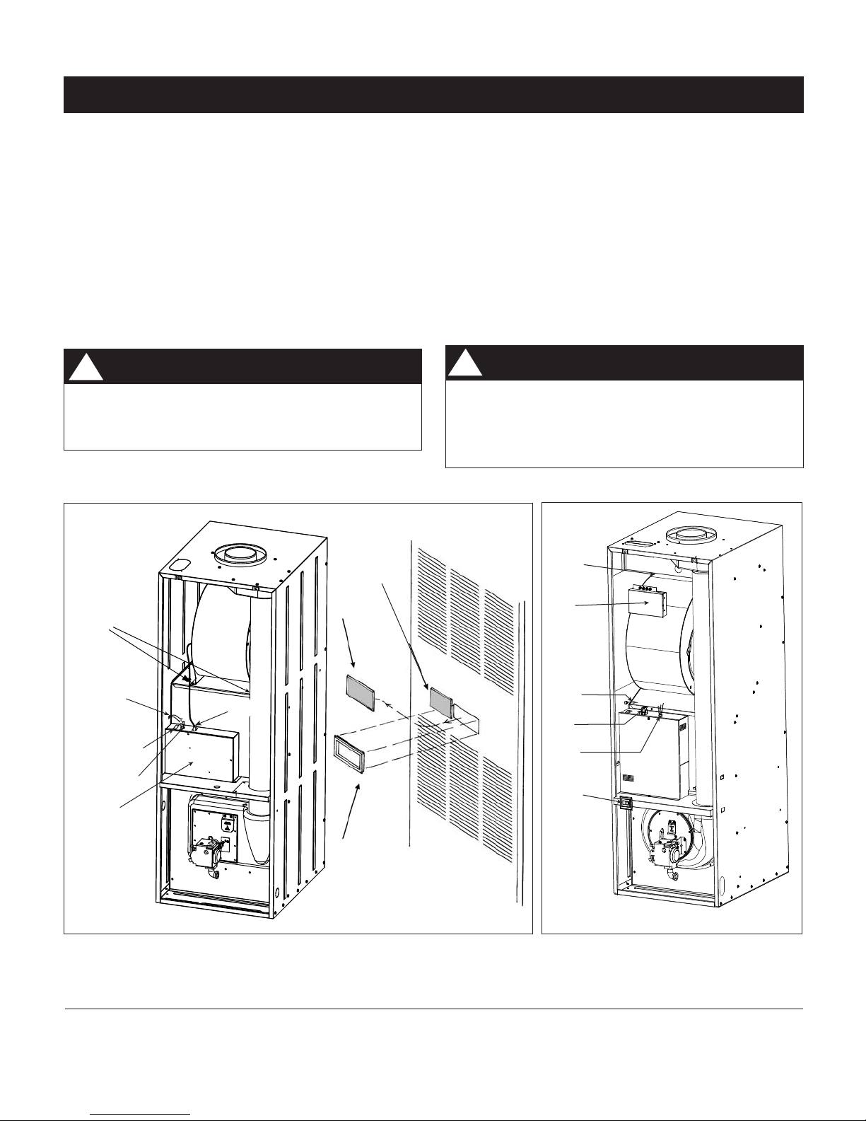
Blower
Screws
Field Installed
Thermostat Wires
Furnace
System Switch
Furnace
Thermostat Wires
Furnace
Control Box
Blower
Plug
Decorative
Nameplate
Insert
Additional
Nameplate Insert
(on older models)
Door Control
Frame
Blower
Screw
Relay
Box
Field Installed
Thermostat
Wires
Blower
Plug
Thermostat
Leads
Fan On/Auto
Switch
(on Heating
only Models)
Installation Instructions
For MGHA and MMHA Series, Models -05 only, and M1 Series Furnaces
The p/n 903092A 2-wire and p/n 902898A A/C Heat Pump (4 to 7 wire) Relay Boxes install with current M1, MGHA and MMHA models of NORDYNE gas furnaces with the new standardized blower
assembly. The 2-wire Relay Box has control switches which are operable through an opening in the
furnace door on MGHA and MMHA furnaces.
IMPORTANT INFORMATION
Read all instructions carefully before starting the installation. Specifi cations or designs are subject
to change or to discontinuance without notice and without incurring obligations.
DANGER:
WARNING:
!
Improper installation may damage equipment,
can create a hazard, and will void the warranty.
!
Shut off electrical supply to the furnace at
the household breaker box to prevent electrical shock which could cause personal injury.
These instructions are primarily intended to assist qualifi ed individuals experienced in the proper installation of heating and/or air
Figure 1. MGHA and MMHA Series Gas Furnace
conditioning appliances. Some local codes require licensed installation/service personnel for this type of equipment. Read all instruc-
tions carefully before starting the installation.
Fig 2. M1* Furnace
INSTALLATION SEQUENCE
1. Remove the furnace door. Shut off power to the furnace.
For MGHA and MMHA Furnaces:
For a 2-wire relay box application, remove the door insert
from the furnace door and replace it with the door control
frame provided with the relay box (see Figure 1).
2. See Table 1 to determine whether the factory installed
blower is acceptable for use with the selected cooling
application.
For MGHA and MMHA Furnaces:
To change out the furnace blower, unplug the motor plug
from the furnace. Remove the two screws on the top of
the blower deck, one on each side of the blower (see
Figure 1), and slide the blower out of the furnace. Slide
the new blower into the blower mounting guides. Do not
yet secure with the screws previously removed.
For M1 Furnaces Only:
To change out furnace blower, unplug the motor plug
from the furnace. Remove the screws on the left side
of the blower (see Figure 2) and lift the blower out of
the furnace. Place the new blower into the mounting
guides.
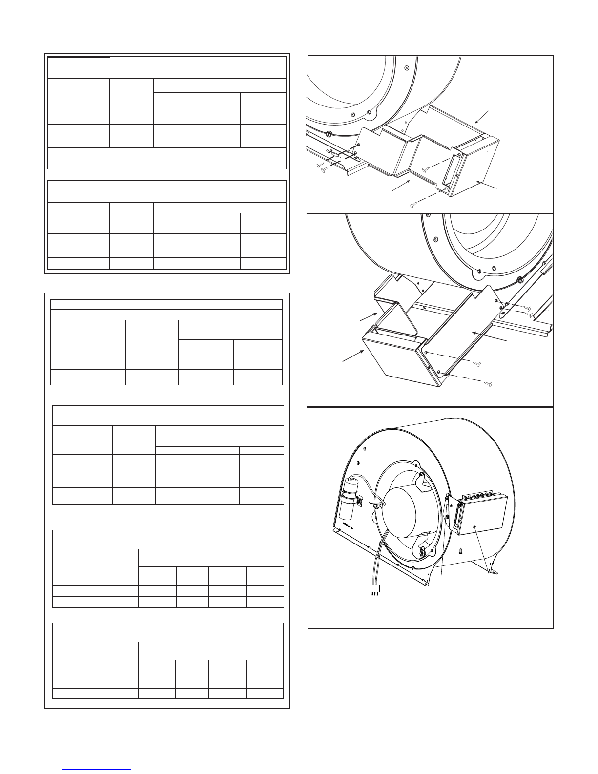
3. Remove the cover from the relay box by removing the
screw from each side.
Blower Speed Selection:
IMPORTANT: For the 2-Wire Relay Box (only after the
cover has been reattached), now attach two red caps
(provided in plastic bag) to the switches that stick through
the bezel on the sheet metal cover (see Figure 5, Items
6 and 7).
4. For MGHA and MMHA Furnaces Only:
If not already completed, remove the two screws on the
top of the blower deck, one on each side of the blower.
(See Figure 1) Slide the blower partially out of the furnace.
Attach the relay box bracket(s) to the blower as shown
in Figure 3 using the screws provided. Next, attach the
relay box to the brackets as shown in Figure 3 using the
remaining screws provided. Slide the blower back into
the furnace and secure with the two screws previously
removed.
5. Unplug the blower plug from the furnace control box
and disconnect the fi eld installed thermostat wires from
the furnace. Remove the label from the yellow furnace
thermostat wire and strip it about 3/8". (For M1, this is
the grey wire.)
Find the 6-wire harness supplied with the relay box.
Connect its 8 circuit in-line connector into the side of
the relay box. Connect the 6 circuit matrix connector on
the other end of the harness into the furnace where the
blower was plugged. Wire nut the remaining harness
wires to the furnace thermostat wires (see Figure 4).
• HEATING - Move the orange wire on the circuit board
to one of the four quick-connects labeled with heating
blower speeds.
• COOLING - Move the violet wire on the circuit board to
one of the three quick-connects labeled with cooling
blower speeds.
• ONE SPEED BLOWER - Both the orange wire (heating)
and the violet wire (cooling) must be connected to the
H(high) quick-connect.
• TWO SPEED BLOWER - See Table 2 for the appropriate
speed connections.
• THREE SPEED BLOWER - See Table 2 for the appropriate speed connections.
• FOUR SPEED BLOWER - See Table 2 for the appropriate
speed connections
For M1 Furnaces Only:
Discard the brackets and remove the relay box cover.
Mount the relay box on the top side of the blower using
the two self-tapping screws provided. The thermostat
terminations should be towards the top of the furnace.
The furnace door should not interfere with the relay box.
Reattach the relay box cover.
For Furnace Models MGHA & MMHA
Cool Capacity (Tons) Blower Kit No.
1.5-2.0 Standard
2.0-3.5 902809
2.0-4.0 902810
*The blower shipped with the furnace can be used for this
cooling capacity.
Table 1. Blower Selection - MGHA & MMHA
For Furnace Models M1
Cool Capacity (Tons) Blower Kit No.
2.0 or 2.5 Standard*
2.0-3.0 903412
2.0-4.0 903413
2.0-5.0 903414
*The blower shipped with the 056 furnace can be used
for 2.0 tons, the blower shipped with the 070 furnace can
be used for 2.5 tons.
Table 1A. Blower Selection - M1
2
Blower Speed Selection Chart
For use with Blower Kit No. 902809
Cooling Speed/ Evap Coil
024, 030 036
Furnace Input
Heating
Speed
Setting
086 M* M* H H
070, 075, 077 L** M* H H
056, 066, 070 L** M* H H
*MH on Relay Box circuit board.
**ML on Relay Box circuit board.
042, 046 &
048
Bracket -Right
Blower Speed Selection Chart
For use with Blower Kit No. 902809
Cooling Speed/ Evap Coil
024, 030 036
042, 046 &
Furnace Input
Heating
Speed
Setting
086 M* M* H H
070, 075, 077 L** M* H H
056, 066, 070 L** M* H H
Table 2. Three and Four Speed Blower Speed Selec-
tion for MG & MM - 05 Models
Blower Speed Selection Chart
For use with Blower Kit No. 903412 1/3 HP 2 Speed
Furnace Input
Heating
Speed
Setting
Cooling Speed/ Evap Coil
024 036 & 030
077, 086, 090 H ML* H
056, 066, 070 ML* ML* H
*ML on Relay Box circuit board is low speed.
Blower Speed Selection Chart
For use with 3 Ton 3 Speed Blowers
Furnace Input
Heating
Speed
Setting
Cooling Speed/ Evap Coil
024 030 036
056 L** L** M* H
048
Bracket
- Left
Relay Box
Bracket -
Left
Relay Box
Bracket
- Right
p/n 903092A, 2-wire relay
066, 070, 077 M* L** M* H
086, 090 H L** M* H
**L is ML on circuit board.
*M is MH on circuit board.
Blower Speed Selection Chart
For use with Blower Kit No. 903413 1/2 HP 4 Speed
Furnace
Input
Heating
Speed
Setting
Cooling Speed/ Evap Coil
024
030 &
036
042 048
077, 086, 090 ML ML ML MH H
056, 066, 070 L ML ML MH H
Blower Speed Selection Chart
For use with Blower Kit No. 903414 3/4 HP 4 Speed
Furnace
Input
Heating
Speed
Setting
Cooling Speed/ Evap Coil
024
030 &
036
042 048
077, 086, 090 ML ML ML MH H
056, 066, 070 L ML ML MH H
Table 2A. Blower Speed Selection M1 Models
Bracket
Relay Box
p/n 902898A, A/C Heat Pump
(4-7 wire) relay box
Figure 3. Relay Box Installation
MGHA & MMHA Only
3
 Loading...