

Nordyne E3EB-017H, E3EB-010H, E3EB-020H, E3EB-023H, E3EX-010 Owner's Manual & Installation Instructions
...Page 1
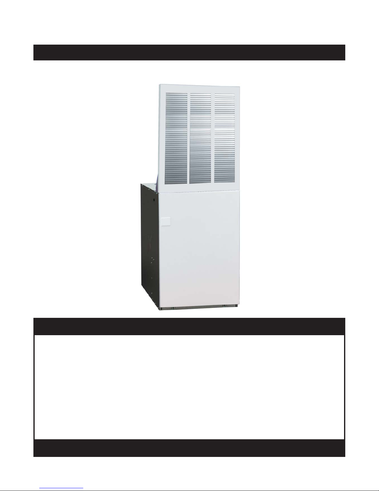
Downfl ow, Upfl ow Electric Furnaces
Owners Manual & Installation Instructions
E3 Series (Air Conditioner / Heat Pump Air Handler)
User, please read this information thoroughly and become familiar with the capabilities and
use of your appliance before attempting to operate or maintain this unit. Keep this literature
where you have easy access to it in the future. If a problem occurs, check the instructions and
follow recommendations given. If these suggestions don’t eliminate your problem, call your
servicing contractor.
The Installation Instructions are primarily intended to assist qualifi ed individuals experienced
in the proper installation of this appliance. Some local codes require licensed installation/
service personnel for this type of equipment. Please read all instructions carefully before
starting the installation.
DO NOT DESTROY. PLEASE READ CAREFULLY AND
KEEP IN A SAFE PLACE FOR FUTURE REFERENCE.
IMPORTANT
Page 2

TABLE OF CONTENTS
USER INFORMATION
IMPORTANT SAFETY INFORMATION .......................3
OPERATING INSTRUCTIONS .....................................3
Cooling Operation ................................................... 3
Heating Operation ...................................................3
Operating the Blower Continuously .........................3
Turning the Heater OFF ..........................................4
INSTALLER INFORMATION
IMPORTANT SAFETY INFORMATION .......................5
REQUIREMENTS & CODES .......................................5
Minimum Installation Clearance .............................. 5
Clearances to Combustible Materials .....................5
CIRCULATING AIR REQUIREMENTS ........................ 6
Plenums & Air Ducts ...............................................6
Return Air Connections ........................................6
Supply Air Connections........................................6
Acoustical Ducts ..................................................6
Unconditioned Spaces.............................................7
Closed-Off Spaces ..................................................7
Filtering Methods - Downfl ow Furnaces .................. 7
Non-Ducted Return Air ........................................7
Without AC or HP Uncased Coil ......................7
With AC or HP Uncased Coil ...........................7
With Optional Coil Housing ..............................7
Ducted Return Air ................................................7
Without Optional Coil Housing .........................7
With Optional Coil Housing ..............................7
Filtering Methods - Upfl ow Furnaces .......................7
Non-Ducted Return Air ........................................7
Without Optional Upfl ow Stand ........................7
With Optional Upfl ow Stand .............................7
Ducted Return Air ................................................7
FURNACE INSTALLATION .........................................8
General nformation .................................................8
Before You Install this Furnace ................................8
Locating the Unit .....................................................8
Optional Equipment .................................................8
Return Air Grille ...................................................8
Automatic Furnace Damper ................................. 8
Duct Connectors for Downfl ow Systems .............. 8
Locating & Cutting Floor Openings .........................9
UNIT MAINTENANCE ..................................................4
Furnace Filter ..........................................................4
Coil Filter .................................................................4
Blower Compartment ..............................................4
TROUBLESHOOTING .................................................4
Standard Duct Connector Installation ...................10
Narrow Duct Connector Installation ......................10
Round Duct Connector Installation .......................11
Alcove Installations ...............................................11
Closet Installations ................................................11
Downfl ow Furnaces ...............................................11
Upfl ow Furnaces ...................................................12
Over the Floor Return Air (Non-Ducted) ............12
Through the Floor Return Air (Ducted) ..............13
ELECTRICAL WIRING ...............................................13
Line Voltage Wiring ................................................13
Connecting Supply Service Wires .........................14
Grounding ..............................................................14
Thermostat / Low Voltage Connections .................14
Selecting Blower Speed ........................................14
Changing Blower Speed ........................................15
Blower Installation .................................................15
Installing Control Circuit Wiring .............................15
START-UP & ADJUSTMENTS ...................................16
Pre-Start Checklist ................................................16
Start-Up Procedures ..............................................16
FIGURES & TABLES .................................................17
Figure 20. Furnace Components ..........................17
Figure 21. Furnace Physical Dimensions ..............18
Figure 22. Upfl ow Stand Dimensions ....................18
Table 6. Unit Specifi cations ...................................19
Table 7. Electrical Specifi cations ...........................20
Figure 23. E3EB-010H Wiring Diagram .................21
Figure 24. E3EB-012H Wiring Diagram .................22
Figure 25. E3EB-015H & 017H W.D. .....................23
Figure 26. E3EB-020H, 023H, & 5 Ton W.D. .........24
INSTALLATION PERFORMANCE CHECKLIST .......28
2
Page 3
USER INFORMATION
IMPORTANT SAFETY INFORMATION
Safety markings are used to designate a degree or level
of seriousness and should not be ignored. WARNING
indicates a potentially hazardous situation that if not
avoided, could result in personal injury or death. CAUTION
indicates a potentially hazardous situation that if not
avoided, may result in minor or moderate injury or proper ty
damage.
WARNING:
Improper service, adjustment or maintenance
of unit may cause fi re, electrical shock, or
hazardous conditions which may result in
personal injury, property damage, or death.
Installation or servicing should only be
performed by qualified trained personnel
thoroughly familiar with this type equipment
WARNING:
Do not use this furnace if any part has been under
water. A fl ood damaged furnace is extremely
dangerous. Attempts to use the furnace can
result in fi re or explosion. A qualifi ed service
agency should be contacted to inspect the
furnace and to replace any electrical or control
system parts that have been wet or under water.
OPERATING INSTRUCTIONS
NOTE: Thermostat styles vary. Some models may not
include the AUTO mode and others will have the AUTO
in place of the HEAT and COOL. Others may include all
three. Please refer to the thermostat manufacturer’s User
manual for detailed programming instructions.
WARNING:
Do not store or place fl ammable or vaporous
materials (paint thinners, etc.) in the vicinity
of this appliance. Failure to comply may cause
fi re, explosion, or other hazardous conditions
which may result in serious injury, death or
property damage.
The following list of chemicals should not be used or
stored near the furnace:
• Chlorinated cleaners
• Water softening chemicals
• De-icing salts or chemicals
• Household Cleaning Solutions
• Printing inks, paint removers, varnishes, etc.
• Cements and glues
• Antistatic fabric softeners
NOTE: Allow at least one hour for the room temperature
to stabilize before you make a second adjustment to
the thermostat setting. After the desired comfort level is
established, make only small adjustments to the thermostat
setting to meet changing temperature conditions.
Cooling Operation
1. Set the thermostat’s system mode to COOL or AUTO
and change the fan mode to AUTO. See Figure 1.
2. Set the temperature selector to the desired temperature
level. The outdoor fan, compressor, and blower
motor will all cycle on and off to maintain the indoor
temperature at the desired cooling level.
Heating Operation
1. Set the thermostat’s system mode to HEAT or AUTO
and change the fan mode to AUTO. See Figure 1.
2. Set the temperature selector to the desired temperature
level. The compressor, outdoor fan, and blower motor
will cycle on and off to maintain the indoor temperature
at the desired heating level.
Operating the Indoor Blower Continuously
The continuous indoor blower operation is typically used to
circulate the indoor air to equalize a temperature unbalance
due to a sun load, cooking, or fi replace operation.
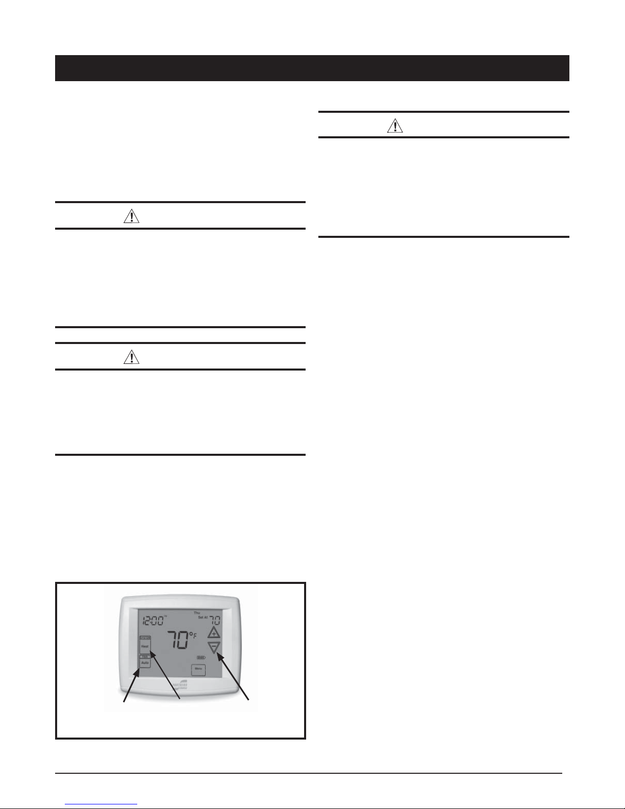
Fan
Mode
Figure 1. Digital Thermostat
System
Mode
Temperature
Selector
Set the thermostat fan mode to ON (Figure 1). The indoor
blower starts immediately, and will run continually until the
fan mode is reset to AUTO.
The continuous indoor blower operation can be obtained
with the thermostat system mode set in any position,
including OFF.
3
Page 4

USER INFORMATION
Turning the Heater OFF
Change the thermostat’s system mode to OFF and the fan
mode to AUTO (See Figure 1). NOTE: The system will not
operate, regardless of the temperature selector setting.
CAUTION:
For optional A/C or H/P systems, always wait
at least fi ve minutes after the system shuts off
before restarting the system.
UNIT MAINTENANCE
WARNING:
Shut off all electrical power to the unit before
performing any maintenance or service on the
system. Failure to comply may result in personal
injury or death.
CAUTION:
There are No user serviceable parts inside the
control panel. DO NOT OPEN.
NOTE: All servicing of this heating appliance other than
the normal maintenance described in this section must
be done by authorized trained service personnel. Do
not attempt any servicing which requires opening of the
control panels.
• Proper maintenance is most important to achieve the
best performance from the appliance and should be
performed frequently at the beginning of each heating
season.
• Keep the area surounding the unit clean. Keep the unit
clear of obstructions.
renovated homes may require more frequent changing
until the construction dust has minimized. Filter sizes
shown in Table 6 (page 19) are available at most local
retailers.
necessary with fi lter of same dimensional size
•
Filters designed to remove smaller particles such as
pollen, may require additional maintenance.
Coil Filters
If a cooling coil is installed on your unit, the furnace fi lter
is not used. Remove coil fi lters, wash, and allow to dry.
Re-install coil fi lters to their original positions.
Blower Compartment
Dirt and lint can create excessive loads on the motor
resulting in higher than normal operating temperatures and
shortened service life. Vacuum or wipe clean the interior
of furnace cabinet. Clean all lint and dust from around the
furnace. It is recommended that the blower compartment
be cleaned of dirt or lint that may have accumulated in
the compartment or on the blower and motor as part of
regular maintenance.
Inspect fi lters frequently and replace when
TROUBLESHOOTING
If the unit fails to operate, check the following:
• Check the thermostat setting. Make sure the system
mode and temperature settings are correct.
• Check the electrical panel for tripped circuit breakers.
• Check the fi lters for dust accumulation.
• Check the unit and make sure it is clean and not covered
with grass or leaves.
• If the items above don’t resolve your problems, then
call your nearest service technician. Please specify
the complete model and serial numbers shown on the
furnace data label for all warranty service and when
ordering replacement parts or optional equipment. Refer
to the replacement parts list provided with the furnace
for part numbers.
Furnace Filter
WARNING:
Never operate the furnace without a fi lter in
place. Accumulating dust in the return air can
build up on internal components, resulting
in loss of effi ciency, equipment damage, and
possible fi re.
• E3 Furnaces are supplied with a single air fi lter when
shipped from the factory. It is recommended that the fi lter
be cleaned or replaced monthly. Newly built or recently
4
Page 5
INSTALLER INFORMATION
IMPORTANT SAFETY INFORMATION
INSTALLER: Please read all instructions before servicing
this equipment. Pay attention to all safety warnings and
any other special notes highlighted in the manual. Safety
markings are used frequently throughout this manual to
designate a degree or level of seriousness and should not
be ignored. WARNING indicates a potentially hazardous
situation that if not avoided, could result in personal injury
or death. CAUTION indicates a potentially hazardous
situation that if not avoided, may result in minor or moderate
injury or property damage.
REQUIREMENTS & CODES
WARNING:
This unit must be installed in accordance
with instructions outlined in this manual
during the installation, service, and operation
of this unit. Unqualifi ed individuals should
not attempt to interpret these instructions or
install this equipment. Failure to follow safety
recommendations could result in possible
damage to the equipment, serious personal
injury or death.
• The installer must comply with all local codes and
regulations which govern the installation of this type
of equipment. Local codes and regulations take
precedence over any recommendations contained in
these instructions. Consult local building codes and the
National Electrical Code (NEC) for special installation
requirements.
• All electrical wiring must be completed in accordance
with local, state and national codes and regulations and
with the National Electric Code (ANSI/NFPA 70) or in
Canada the Canadian Electric Code (CSA Z240.6.1, &
Z240.9.1).
• Design and construction of the home duct system,
must be in accordance with: HUD Manufactured Home
Construction & Safety Standard (Title 24, Part 3280)
and American National Standards (ANSI) A119.11,
C1-NFPA 7
• Follow all precautions in the literature, on tags, and
on labels provided with the equipment. Read and
thoroughly understand the instructions provided with
the equipment prior to performing the installation and
operational checkout of the equipment.
• This air handler may not be used for temporary heating
of buildings or structures under construction.
Minimum Installation Clearances
• Access for positioning and servicing the unit must be
considered when locating unit. The need to provide
clearance for access to panels or doors may require
clearance distances over and above the requirements.
For alcove installations allow 18 (46cm) inches
minimum clearance from the front of the unit for
future servicing. Closet installations require 36
inches minimum.
• This appliance must be installed in accordance with
clearances listed in Table 1. The furnace must be installed
with ample clearance for easy access to the air fi lter,
blower assembly, burner assembly, controls, and vent
connections.
• Locate and install this unit in position as specifi ed on
page 8. This unit is designed only for Indoor installations
and should be located with consideration of minimizing
the length of the supply and return ducts. See Table 4
(page 15) or the rating plate for circulating airfl ow data.
• Suffi cient clearance for unobstructed airfl ow through a
louvered door must be maintained in order to achieve
rated performance. Air return to the furnace must have
the minimum required total free area:
200 in
2
(1290 cm2 ) for furnace only. May also include
return air grille and frame assembly P/N 902989 or wall
mount grille P/N 902999).
235 in
2
(1516 cm2 ) with 4 ton A.C. or H.P. installed.
250 in2. (1613 cm2 ) with 4 ton A.C. or H.P. installed &
1” special clearance.
390 in2 (2516 cm2 ) with up to 5 ton A.C. or H.P. installed.
Clearances to Combustible Materials
•
This furnace is Design Certifi ed in the U.S. and Canada
by CSA International for the minimum clearances to
combustible materials. NOTE: The furnace is listed for
installation on combustible or non-combustible fl ooring.
To obtain specifi c clearance information, refer to the
furnace rating plate, located inside of the furnace cabinet.
• 0” from all surfaces of furnace cabinet, ducts, optional
coil housing and plenum connector. No separate subbase
required for installations on combustible fl ooring.
ALL MODELS CLOSET ALCOVE
Front ** 6" 18"
Back 0" 0"
Sides* 0" 0"
To p 0 " 0 "
Top & Sides of Duct 0" 0"
Bottom of Duct 0" 0"
** Service Clearance
* For upfl ow application using upfl ow stand, 1” minimum per side.
Table 1. Minimum Clearance Requirements
5
Page 6

CIRCULATING AIR REQUIREMENTS
WARNING:
All return ducts must be secured to the furnace
with sheet metal screws. All return ducts must be
adequately sealed. When return air is provided
through the bottom of the unit, the joint between
the furnace and the return air plenum must be
air tight.
Return air and circulating air ducts must not be
connected to any other heat producing device
such as a fi replace insert, stove, etc. This may
result in fi re, explosion, carbon monoxide
poisoning, personal injury, or property damage.
Plenums & Air Ducts
This unit is designed only for use with a supply and return
duct. Air ducts should be installed in accordance with the
standards of the National Fire Protection Association
Standard for Installation of Air Conditioning Systems
(NFPA 90A), Standard for Installation of Residence Type
Warm Air Heating and Air Conditioning Systems (NFPA
90B), and all applicable local codes. NFPA publications
are available by writing to: National Fire Protection
Association, Batterymarch Park, Quincy, ME 02269 or visit
www.NFPA.org on the web.
• Plenums and air ducts must be installed in accordance
with the Standard for the Installation of Air Conditioning
and Ventilating Systems (NFPA No. 90A) or the
Standard for the Installation of Warm Air Heating and
Air Conditioning Systems (NFPA No. 90B).
• Design the air ducts according to methods described
by the Air Conditioning Contractors of America (ACCA).
• Air ducts must be aluminum, tin plate, galvanized sheet
steel, or other approved materials for outlet or return air
ducts.
• Snap-Lock or Pittsburgh-Lock seams are preferred. All
other types of seams must be made tight to prevent
leakage.
• It is good practice to seal all connections and joints
with industrial grade sealing tape or liquid sealant.
Requirements for sealing ducts vary from region to
region. Consult with local codes for requirements specifi c
to your area.
• Gas piping must not run in or through any of the air duct
system.
• Applicable installation codes may limit the furnace to
installation in a single-story residence only. Furnace
installations other than closet or alcove require ducted
return air systems.
Return Air Connections
Air return to the furnace must have a minimum free area
opening (see Table 1). A return air grille for closet or alcove
installations is available. Acceptable closet installations
with return air entering through an opening in the fl oor
or ceiling of a closet, must meet all of the following
requirements:
• The return air opening, regardless of its location in the
closet, must not be smaller than size specifi ed on unit
data label. If located in the fl oor, the opening must be
provided with a means of preventing its inadvertent
closure by fl at object(s) placed over the opening.
• A return air grille must be used when furnace is installed
in a closet or alcove:
Alcove installations: use return air grille & frame assembly
P/N 902989 or equivalent. See Figure 2, page.
Closet installations: use wall mount return air grilled
P/N 902999 or equivalent. NOTE: For 5 ton A.C. or H.P.
system, 155 in
Downfl ow alcove installations: the grille (with frame
provided) may be attached to the top of the furnace and all
paneling and trim fl ushed to it. This installation provides
an access door for future installation of NORDYNE air
conditioning or heat pump coils on top of the furnace.
• Materials located in return air duct system must have
a fl ame-spread classifi cation of 200 or less.
• Noncombustible pans having 1” upturned fl anges must
be located beneath openings in a fl oor-return duct
system.
• Wiring materials located in return duct system must
conform to NEC Article 300-22(c).
• If return air opening is located below top of furnace, a
minimum clearance must be provided between opening
and furnace. See Table 1 (page 5).
Supply Air Connections
• Supply duct system must be designed for proper air
distribution. Static pressure measured externally to
furnace shall not exceed static pressure rating listed
on furnace nameplate.
• Duct system must be designed so that no supply registers
are located in duct system directly below the furnace.
Acoustical Ducts
Certain installations may require the use of acoustical
lining inside the supply duct work.
• Acoustical insulation must be in accordance with the
current revision of the Sheet Metal and Air Conditioning
Contractors National Association (SMACNA) application
standard for duct liners.
• Duct lining must be UL classifi ed batts or blankets with
a fi re hazard classifi cation of FHC-25/50 or less.
• Fiber duct work may be used in place of internal duct
liners if the fi ber duct work is in accordance with the
current revision of the SMACNA construction standard
on fi brous glass ducts. Fibrous duct work and internal
acoustical lining must be NFPA Class 1 air ducts when
tested per UL Standard 181 for Class 1 ducts.
2
(1,000 cm2 ) must be added.
6
Page 7

Unconditioned Spaces
Frame
Top of
Furnace
Fasteners (4)
Grille
Furnace Filter
(not used with
A/C or H/P)
All duct work passing through unconditioned space must
be properly insulated to minimize duct losses and prevent
condensation. Use insulation with an outer vapor barrier.
Refer to local codes for insulation material requirements
Closed-Off Spaces
Living space not served by, and closed off from the return air
ducts to the furnace (by doors, sliding partitions, and other
means) must be provided with permanent, uncloseable
openings in the doors or partitions to allow air to return to
the furnace from all parts of the home. Return air grilles,
with a minimum open area of one square inch for every
fi ve square feet of living space closed off from the furnace,
must be provided in the door or room partition.
Figure 2. Grille Support Frame & Grille Assembly
Filtering Methods - Downfl ow Furnaces
Non-Ducted Return Air
For unducted return air systems, either the optional grille
and frame assembly or the optional wall mount grille is
recommended.
Without A/C or H/P uncased coil:
• Use the fi lter supplied with the furnace; ensure that
the fi lter is installed mat side down between the fi lter
retainer and furnace top. See Figure 2.
With A/C or H/P uncased coil:
• Use the optional coil fi lters; the fi lter supplied with the
furnace is not used; REMOVE AND DISCARD THIS
FILTER.
With optional coil housing:
• See coil cabinet instructions for specifi c fi ltering methods.
Ducted Return Air
For ducted return air systems with air conditioners or heat
pumps, either providing an access panel in the duct or
using the optional coil cabinet (Figure 3) is recommended.
The duct system must be properly sized to account for
any additional external static pressure produced from the
chosen fi ltering method.
Without optional coil housing:
• Install a fi lter with a minimum unrestricted medium area
of 324 in
2
in the duct above the coil that is accessible
for monthly cleaning or replacement by homeowner.
With optional coil housing:
• Install a fi lter with a minimum unrestricted medium area
of 324 in
2
in the duct above the coil that is accessible
for monthly cleaning or replacement by homeowner.
Filtering Methods - Upfl ow Furnaces
Non-Ducted Return Air
Furnaces may be installed with unducted or ducted return
air. For unducted systems with air conditioners or heat
pumps, the following optional equipment is recommended:
upfl ow stand, coil cabinet, upfl ow duct connector, and
wall mount grille.
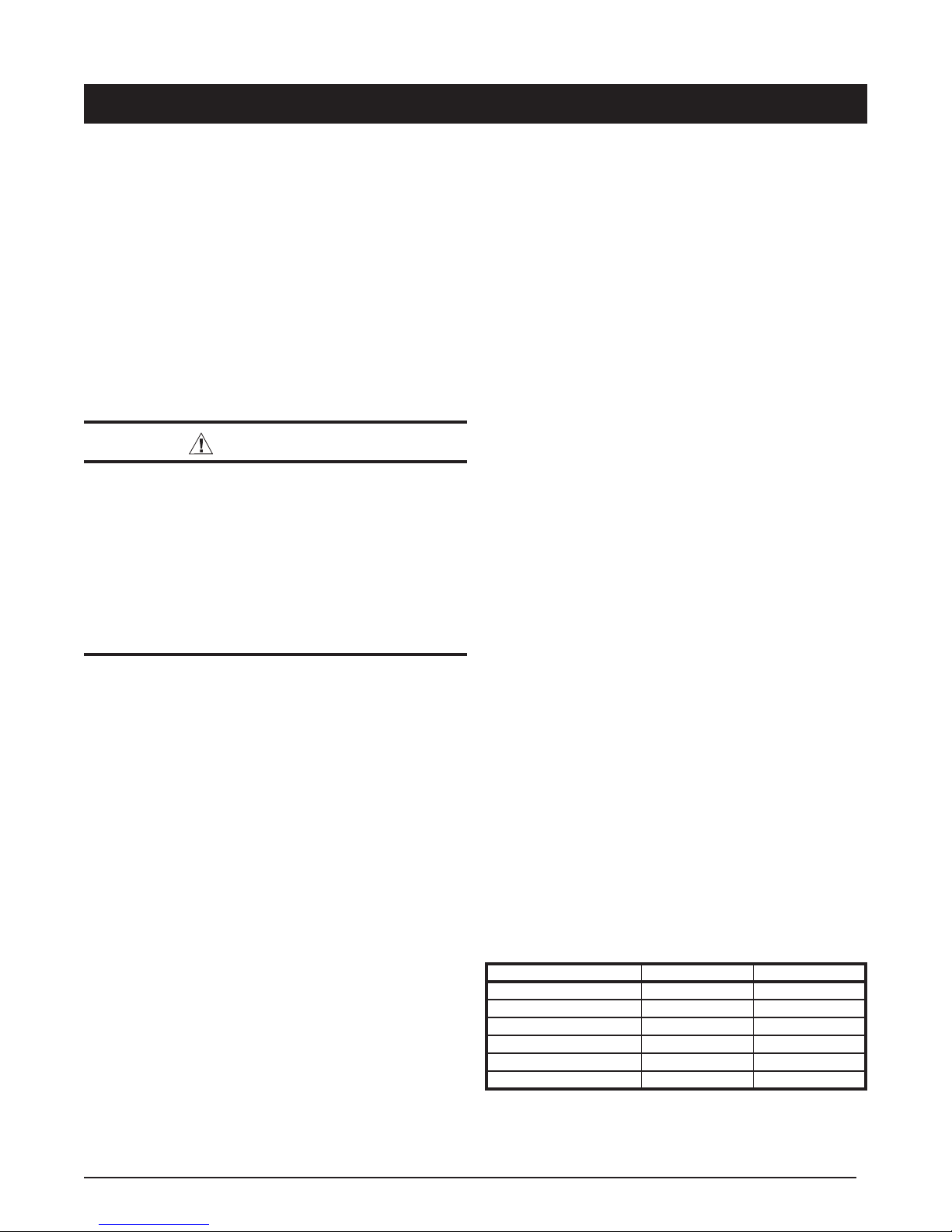
20" (508 mm)
Cabinet
Insulation
29"
(737 mm)
23 3/4" (603 mm)
Figure 3. Upfl ow Coil Cabinet
Without optional upfl ow stand:
• Install a fi lter with a minimum unrestricted medium area
of 324 in
2
below the coil cabinet/furnace assembly that
is accessible for monthly cleaning or replacement by
the homeowner
With optional upfl ow stand:
• Stand (Figure 4, page 8) must use two fi lters: one is
supplied with the stand and the other MUST be removed
from the furnace and placed in the stand. See instructions
supplied with the upfl ow stand for additional details.
Ducted Return Air
For ducted systems with air conditioners or heat pumps,
the following optional equipment is recommended: coil
cabinet and upfl ow duct connector.
• Install a fi lter with a minimum unrestricted medium area
of 324 in2 below the coil cabinet/furnace assembly that
is accessible for monthly cleaning or replacement by
the homeowner
7
Page 8
24 3/4” (628 mm)
20”
(508 mm)
20” (508 mm)
Upflow Stand
Figure 4. Optional Upfl ow Stand
FURNACE INSTALLATION
NOTE: Since all installations are different, the sequence of
these steps may differ from the actual installation. These
installation procedures are suggested for typical furnace
installations. Only qualifi ed HVAC technicians should
install this furnace.
General Information
The E3 Electric furnace is designed only for indoor
installations and can be readily connected to the high
static duct system of a home. Units are approved for single/
multistory residential or mobile/modular/manufactured
structures in upfl ow, downfl ow, (freestanding/closet/
alcove) confi gurations.
This appliance will provide many years of safe and
dependable comfort, providing it is properly installed
and maintained. Abuse, improper use, and/or improper
maintenance can shorten the life of the appliance and
create unsafe hazards. Please read all instructions before
installing the unit.
Approved installation, operation, and maintenance of
this appliance must be in accordance with the listed
specifi cations contained in these instructions and other
documents supplied with the furnace and/or optional air
conditioning equipment. Unless it is noted differently in this
manual, only use factory authorized kits and accessories
when modifying this appliance. Refer to local authorities
having jurisdiction for further information.
local building codes. If there is any question concerning
the power supply, contact the local power company.
Verify the air delivery of the furnace is adequate to
handle the static pressure drop of the coil, fi lter, and
duct work.
Locating the Unit
• Survey the job site to determine the best location for
installing the unit. Consideration should be given to
availability of electric power, service access, and noise.
• The dimensions of the room or alcove must be able
to accommodate the overall size of the unit and the
installation clearances in Table 1 (page 5). Physical
dimensions for this furnace are shown in Figure 21
(page 18). If an upfl ow stand will be used, see Figure
22 for component dimensions.
• The unit must be leveled at installation and attached to
a properly installed duct system.
• The surface that the furnace is mounted on must provide
sound physical support of the unit.
Optional Equipment
NOTE: Refer to the instructions supplied with any additional
accessories for further installation details.
Return Air Grille
A return air grille and frame assembly (Figure 2, page
7) is available for use in unducted return air installations.
In downfl ow alcove installations, the grille and frame
assembly may be mounted directly to the top of the furnace.
In closet installations, a wall mount grille is available for
attachment to a door or wall.
Optional Automatic Furnace Damper (901083)
Furnace may be equipped with the optional automatic
damper when a packaged air conditioner is installed and
connected to the warm air duct system. This damper (not
required) prevents cooled air from discharging through
the furnace cabinet, causing excessive cooling of the
immediate area. Refer to the instructions supplied with
the damper for details.
Duct Connectors for Downfl ow Systems
Duct connectors are recommended for heated air
distribution in under-the-fl oor duct systems. With this
system, furnaces may be installed on combustible fl ooring
without a separate sub-base. The furnace rear mounting
plate (Figure 8, page 10) supplied with the duct connectors
is recommended for use with this type of installation.
Before You Install this Furnace
This equipment is securely packaged at the time of
shipment and upon arrival should be carefully inspected
for damage prior to installing the equipment at the job
site. Claims for damage (apparent or concealed) should
be fi led immediately with the carrier.
Check the electrical supply and verify the power supply
is adequate for unit operation. The system must be wired
and provided with circuit protection in accordance with
8
Page 9

REAR WALL OF CLOSET OR ALCOVE
1 3/4" MIN.
REAR WALL OF CLOSET OR ALCOVE
2 3/8" MIN.
23 3/4"
OPTIONAL
REFRIGERANT LINE
3 1/8” X 5 3/4”
23 3/4"
FLOOR CUT-OUT
17 1/2” X 14”
18 5/8"
FOR UPFLOW
FURNACES WITH
STD. DUCT
CONNECTORS
C
L
3”
10"
20"
STANDARD DUCT CONNECTOR
REAR WALL OF CLOSET OR ALCOVE
1 3/4"
MIN.
FLOOR CUT-OUT
14 1/4” DIAMETER
FOR UPFLOW
18 5/8"
FURNACES WITH
ROUND DUCT
CONNECTORS
C
L
FURNACE OUTLINE
3/4"
FURNACE
DOOR
FURNACE OUTLINE
3/4"
23 3/4"
OPTIONAL
REFRIGERANT LINE
4 1/4” X 3 3/4”
23 3/4"
FLOOR CUT-OUT
14 1/2” X 14 1/2”
17"
FOR DOWNFLOW
FURNACES WITH
STD. DUCT
CONNECTORS
C
L
5”
10"
20"
3 3/8”
STANDARD DUCT CONNECTOR
REAR WALL OF CLOSET OR ALCOVE
2 3/8"
MIN.
FLOOR CUT-OUT
17"
14 1/4” DIAMETER
FOR DOWNFLOW
FURNACES WITH
ROUND DUCT
CONNECTORS
C
L
16 5/8"
FURNACE OUTLINE
OPTIONAL SUPPLY
WIRE ENTRANCE
3” X 6 1/4”
3/4"
FURNACE
DOOR
16 5/8"
FURNACE OUTLINE
OPTIONAL SUPPLY
WIRE ENTRANCE
3” X 6 1/4”
3/4"
OPTIONAL
REFRIGERANT LINE
3 1/8” X 5 3/4”
10"
3”
FURNACE
20"
DOOR
ROUND DUCT CONNECTOR
Figure 5. Cut-Out Dimensions for Upfl ow
Furnaces
Locating & Cutting Floor Openings
Floor cut-outs must be carefully located to avoid
misalignment of the furnace and air duct. Standard and
round cutouts for upfl ow furnaces are shown in Figure
5. Figure 6 displays the cutouts for downfl ow furnaces.
1. Measure and mark the centerline of the cutout. Provide
minimum clearances at rear and right side walls of
closet or alcove for installation of furnace and wiring.
2. Using the centerline as a starting point, draw the rest
of the duct cut-out to the dimensions shown in Figures
5 or 6. NOTE: Additional provisions may be necessary
for optional air conditioning or heat pump if refrigerant
lines are installed elsewhere than at the front of the
furnace. The refrigerant and entrance supply opening
dimensions may be adjusted ± 1/2”.
3. Cut out the fl oor opening 1/16” larger than the actual
cutout drawn. This will allow some clearance when
installing the duct connector.
OPTIONAL
REFRIGERANT LINE
4 1/4” X 3 3/4”
5”
10"
20"
3 3/8”
FURNACE
DOOR
ROUND DUCT CONNECTOR
Figure 6. Cut-Out Dimensions for Downfl ow
Furnaces
4. Measure from the top of the fl oor down to the top of the
supply air duct to obtain the depth of the fl oor cavity.
NOTE: The depth of the fl oor cavity shown as “X” in
Figure 7 will determine the correct duct connector.
5. Determine which duct connector to use from Table 2
(page 10).
FLOOR OPENING
“X”
SUPPLY AIR DUCT
FLOOR
CAVITY
Figure 7. Floor Cavity
9
Page 10

If Floor Cavity
“X” is:
7/8” / (22) 901987A 904008
2” / (51) 901988A 904009
4-1/4” / (108) 901989A 904010
6-1/4” / (159) 901990A 904011
8-1/4” / (210) 901991A 904012
10-1/4” / (260) 901992A 904013
12-1/4” / (311) 901993A 904014
NOTE: Dimensions shown as Inches / (Millimeter)
Standard Duct Screw Down
Duct Connector
Type & Part Number
Table 2. Duct Connector Sizes
8. Bend both tabs on the mounting plate up 90° as shown
in Figure 9.
9. Seal all connections with industrial grade sealing tape
or liquid sealant.
NOTE: Requirements for sealing ductwork vary
from region to region. Consult with local codes for
requirements specifi c to your area.
DUCT CONNECTOR
SUPPLY
AIR DUCT
Standard Duct Connector Installation
The standard duct connector is designed for use on ducts
12” in width. NOTE: Ducts narrower than 12” may not
allow suffi cient clearances for this type of installation. See
Narrow Duct Connector section.
1. Center the duct connector in the fl oor opening with
bottom tabs resting on top of the supply air duct.
2. Mark the cut-out area on the supply air duct by tracing
around the connector tabs (Figure 8) of the duct
connector.
3. Remove the duct connector and cut out the marked
area of the supply air duct 1/4” larger the actual cutout
drawn.
4. Install the duct connector back in the fl oor opening
with the bottom tabs extending into the supply air duct.
5. Install the mounting plate (Figure 8) under the back
side of the duct connector. Align the screw holes in
both components.
6. Secure the duct connector and the mounting plate to
the wood fl oor with appropriate size screws.
7. Bend the connector tabs on the bottom of the duct
connector upwards and as tight as possible against
the supply air duct.
Bend tabs
Wood Floor
up 90°
BEND TABS TIGHTLY
AGAINST SUPPLY AIR DUCT
Figure 9. Duct Connector Tabs
Narrow Duct Connectors
This attachment method should be used if there is
insuffi cient clearance to bend the tabs on a standard 12”
duct connector.
1. Score and cut the top of the supply air duct as indicated
in Option 1 or Option 2 (Figure 10). With Option 1
choice, cut out the metal from the shaded area.
2. Fold the two fl aps (Options 1 or 2) up to form the
opening for the duct connector.
3. Install the duct connector with the bottom tabs
extending into the supply air duct.
4. Bend the tabs on the bottom of the duct connector
upwards and as tight as possible against the supply
air duct (Figure 11, page 11).
5. Form the fl aps (Options 1 or 2) up against the duct
connector as tight as possible.
6. Secure the duct connector fl aps to the supply air
duct with staples (3 minimum) or if a 2x block/joist is
not provided, use sheet metal screws (2 minimum).
NOTE: The duct connector tabs may be attached to
the air duct with sheet metal screws or other suitable
fasteners as long as the duct connector and the air
duct are securely attached.
Connector
Tabs
Duct
Connector
Supply
Air Duct
Figure 8. Standard Duct Connector Installed
10
Mounting Plate
OPTION 1 OPTION 2
Remove
this
Flap
Cut Here
Cut Here
Cut Here
Cut Here
Fold Flap Here
Remove
this
Flap
Cut Here
Cut Here
Supply
Air Duct
Fold Flap Here
Cut Here
Cut Here
Cut Here
Fold Flap Here
Fold Flap Here
Figure 10. Narrow Air Duct Openings
Page 11

Duct connector tabs
Screws
Mounting
Plate
Round Duct
Connector
14” Supply
Connection
Narrow
Duct
Sheet metal
screws
Duct
Flap
Duct Connector
Staples or sheet metal screws
Narrow
Duct
Narrow
Duct
Figure 11. Narrow Ducts
7. Seal all connections with industrial grade sealing tape
or liquid sealant.
NOTE: Requirements for sealing ductwork vary
from region to region. Consult with local codes for
requirements specifi c to your area.
Round Duct Connector Installation
The 14” round duct connector is designed to connect
directly to a 14” fl exible duct. NOTE: Flexible ducts must
have a minimum temperature rating of 200° F and meet
all applicable codes and standards.
1. Apply a bead of caulking, mastic, or other approved
sealant around bottom side of connector.
2. Install and center the duct connector in the fl oor
opening.
3. Install the mounting plate under the back side of the
duct connector. See Figure 12. NOTE: Align the screw
holes in both components.
4. Secure the duct connector and the mounting plate to
the wood fl oor with appropriate size screws.
5. Connect the round supply duct to the underside of the
duct connector and secure them with fi eld supplied
sheet metal screws.
6. Seal all connections with industrial grade sealing tape
or liquid sealant.
Alcove Installation
1. Cut alcove rough openings to minimum dimensions
shown in Figure 13 (page 12).
2. Attach frame assembly with four fasteners (provided or
equivalent) into pre-punched holes on top of furnace.
See Figure 2 (page 7). NOTE: If additional securing
is required, attach each side of frame assembly to
alcove opening using holes provided.
3. Attach return air grille to frame assembly by hooking
grille over fl ange on top of frame and into channel on
bottom.
Closet Installation
For proper air circulation, closet installations require a
return air grill installed in the door or a partially louvered
door across the opening. For clearances 6” or greater, the
closet must have an open free area of 235 in
2
minimum.
For special clearances between 1” - 5”, requirements are
a louvered door with a minimum of 250 in2 (1613 cm2) free
area. A fully louvered closet door is strongly recommended
for both installation types. For closet installations, the return
air grille mounting frame is not used since the furnace is
located inside the closet. For examples of both types of
installations, see Figure 14 (page 12).
1. Cut return air opening in desired position in door or
wall, preferably above top of furnace. Refer to Table
1 for return air opening requirements.
2. Insert four fasteners, securing grille to door or wall.
Downfl ow Furnaces
For typical unducted return air downfl ow applications,
an air-conditioner or heat-pump coil can be installed by
mounting the coil directly on top of the furnace without
adding sheet metal cavities or cutting and trimming wood
panels. Unducted return air systems may be used for
closet or alcove installations.
The steps below describe installation procedures for
an under-the-fl oor supply duct system with a ducted
or unducted return air system. Duct connectors are
recommended for this application. See Table 2 (page 10).
NOTE: Requirements for sealing ductwork vary
from region to region. Consult with local codes for
requirements specifi c to your area.
Figure 12. Round Duct Connector Installed
1. Route 240V supply circuit(s) and 24V wiring to closet
or alcove. See Figure 21 (page 18) for locations.
2. Remove refrigerant line knockouts in furnace only
when installing indoor coil of an air conditioner or heat
pump system, or for hook-up of a VentilAire accessory
when the furnace is used in the upfl ow position. Refer
to instructions supplied with accessory equipment.
3. Remove unit front door and slide back until bottom
slots in rear of unit engage with both tabs of optional
rear mounting plate. If mounting plate is not used, an
equivalent method of securing the rear of the unit may
be used as long as it prevents displacement during
transport if used in a manufactured home.
NOTE: The furnace does not need to be positoned
against the rear mounting plate. The tabs will engage
into the slots and allow approximately 1/2” of furnace
adjustment front to back and side to side.
11
Page 12

Coil Cabinet
Air Filter
Braced
Mounting
Platform
Front
Grille
Non-combustible
Pan or
Enclosure
WALL
FLOOR
4. Secure front of unit with one or more fasteners at
mounting hole(s) provided or at tie-down tab. See
Figure 21 (page 18).
5. See Electrical Wiring section (page 13) to complete
furnace installation.
Coil Air
Filters
A/C or H/P
Coil
24 3/4"
(629 mm)
Wall
Furnace
Front
(508 mm)
20"
27"
(686 mm)
(1423 mm)
29"
( 737 mm)
Return Air Grille
56"
18"Nearest
Wall or Partition
Figure 13. Alcove Installation
Provide min. 235
sq. in. (1516 cm )
open free area in
front or side wall
or in top of
closet door
0" Side
Clearance
to Furnace
Cabinet
6"
(152 mm)
CLOSET DOOR
Standard Closet Installation
Upfl ow Furnaces
The following steps describe installation instructions for
an overhead supply duct system with a return air system
that can be either over the fl oor (unducted) or through
the fl oor (ducted).
NOTE: The 2 Wire Relay Control is NOT recommended
for upfl ow applications, instead, the AC/HP Relay Control
(4-7 wire) should be used when converting some models
to accept an air conditioner. Refer to the instructions
supplied with the Relay Control for further details.
NOTE: Remove refrigerant line knockouts in furnace only
when installing indoor coil from an air conditioner or heat
pump system.
Refer to instructions supplied with accessory equipment.
Over-the-Floor Return Air System (Non-Ducted)
1. If fl oor underneath furnace is made of combustible
material, locate a pan fabricated of non-combustible
material with 1” upturned fl anges under furnace return
air opening (see Figure 15).
2. Use optional upfl ow stand with fi lters or construct a
suitably braced mounting platform in closet. See Figure
16 (page 13).
3. Route 240V supply circuit(s) and 24V wiring to closet.
See Figure 21 (page 18) for appropriate locations.
4. Position optional coil cabinet onto upfl ow stand or
mounting platform and secure with three or more
fasteners.
5. Position furnace in upfl ow mode onto coil cabinet and
secure with two or more fasteners.
6. Use optional upfl ow duct connector or fi eld supplied
connector to attach furnace to overhead supply duct.
See Figure 16.
7. Install return air grille in closet preferably at same
level as upfl ow stand or below mounting platform. See
Figure 15.
NOTE: Be sure to provide an adequate free return air area
as described in the Closed-Off Spaces section(page 7).
Provide min. 250
sq. in. (1613 cm2 )
open free area in
front or side wall
or in top of
closet door
0" Side
12
Clearance
to Furnace
Cabinet
1"
(25 mm)
Special 1" Clearance
Figure 14. Closet Installation
CLOSET DOOR
Figure 15. Over-the-Floor Return Air System
Page 13

Upflow Duct
Connector
ELECTRICAL WIRING
WARNING:
Furnace
Filter
(one obtained
Upflow Stand
Figure 16. Over-the-Floor Return Air System
with Upfl ow Stand
Through-the-Floor Return Air System (Ducted)
1. Prepare Floor Opening(s):
a. Mark fl oor openings as shown in Figure 5 (page 9).
Provide minimum clearances at rear and left side
walls of closet for installation of furnace and wiring.
b. Cut fl oor opening on outside edge of marked line
so that opening is slightly larger than area marked.
c. Additional provisions may be necessary for optional
air conditioning if refrigerant lines are installed other
than at the front of the furnace.
2. If return air duct is made of combustible material, locate
a pan fabricated of non-combustible material with 1”
upturned fl anges under furnace return air opening.
3. Route 240V supply circuit(s) and 24V wiring to closet.
See Figure 21 (page 18) for appropriate locations.
4. Position optional coil cabinet over fl oor cutout and
secure with three or more fasteners.
5. Position furnace onto coil cabinet and secure with two
or more fasteners.
6. Use optional upfl ow duct connector or fi eld supplied
connector to attach furnace to overhead supply duct.
See Figure 16.
from furnace)
ELECTRICAL SHOCK, FIRE OR EXPLOSION
HAZARD
Failure to follow safety warnings exactly could
result in serious injury or property damage.
Improper servicing could result in dangerous
operation, serious injury, death or property
damage.
• Before servicing, disconnect all electrical
power to furnace.
• When servicing controls, label all wires prior
to disconnecting. Reconnect wires correctly.
• Verify proper operation after servicing.”
• Electrical connections must be in compliance with all
applicable local codes and the current revision of the
National Electric Code (ANSI/NFPA 70).
• For Canadian installations the electrical connections
and grounding shall comply with the current Canadian
Electrical Code (CSA C22.1 and/or local codes).
Line Voltage Wiring
IMPORTANT NOTE: Proper line voltage polarity must be
maintained for the control system to operate correctly.
Verify the incoming neutral line is connected to the
white wire and the incoming HOT line is connected
to the black wire. The furnace will not operate unless
the polarity and ground are properly connected.
IMPORTANT:
Circuit breakers installed in this unit provide
short-circuit protection of the internal wiring
and serve as a disconnect. The circuit breakers
DO NOT provide over-current protection of the
supply wiring and may be sized larger than
the branch circuit protection. Overcurrent
protection of the supply wiring is provided by
the breaker in the distribution panel and must
be sized as shown in Table 7 (page 20).
It is recommended that the line voltage (240 VAC) to
the furnace be supplied from a dedicated branch circuit
containing the correct fuse or circuit breaker for the furnace.
See Table 7 (page 20).for minimum circuit ampacity and
maximum over-current protection. See unit wiring diagrams
(Figures 23 - 26, pages 21 - 24) for wiring details. Electrical
components are shown in
circuit requirements are listed at the top of page 14:
Figure 20 (page 17). Supply
13
Page 14

• -010 model is factory-wired for single-branch supply
circuit only.
• -012 models are factory-wired for single-branch supply
circuit (single-circuit kit factory installed). Dual-branch
circuit can be used by removing factory-installed singlecircuit kit (see Figure 17).
• -015, -017, -020 and -023 models are factory-wired for
dual-branch supply circuit. Single-branch circuit can be
used by installing optional single-circuit kit.
5. To install optional single-circuit kit:
a. Loosen lugs at supply side of circuit breakers.
b. Remove cover from single-circuit kit (if supplied).
c. Insert metal buss bars of kit into lugs of circuit
breaker.
d. Tighten lugs securely (45 in.-lbs. recommended).
6. Connect service ground wire(s) to grounding lug(s)
provided. One ground is required for each supply
circuit used. See Fgiure 20 (page 17).
Connecting Supply Service Wires
Power entrance for all models may be through the right
side or through the bottom of the unit.
1. Remove right-hand control panel (when viewing in
downfl ow position).
2. Locate power supply knockouts in side of unit and in
bottom of unit. Remove appropriate plug(s) or knockout
opening applicable to selected wire size(s).
WARNING:
To avoid personal injury or property damage,
make certain that the motor leads cannot
come into contact with non-insulated metal
components of the unit.
3. Install listed cable connector(s) in opening(s). If metalsheathed conduit is used for incoming power line(s),
provide an approved metal clamp on conduit and
secure it in entrance knockout.
4. Insert supply ser vice wire(s) through cable connector(s)
and connect wires to circuit breakers (Figures 17 &
18). NOTE: To install single-circuit kit, perform step
5. If single-circuit kit installation is not needed, go to
step 6.
Optional
Single Circuit
Adaptor Kit
Circuit Breaker
Wire Assemblies
(Factory Installed)
Circuit Breaker
Bracket
OFF
OFF
60A
60A
ON
ON
Grounding
WARNING:
To minimize personal injury, the furnace cabinet
must have an uninterrupted or unbroken
electrical ground. The controls used in this
furnace require an earth ground to operate
properly. Acceptable methods include electrical
wire or conduit approved for ground service.
Do not use gas piping as an electrical ground!
Thermostat / Low Voltage Connections
• The furnace is designed to be controlled by a 24 VAC
thermostat. The thermostat’s wiring must comply with
the current provisions of the NEC (ANSI/NFPA 70) and
with applicable local codes having jurisdiction.
• The thermostat should be mounted about 5 feet above the
fl oor on an inside wall. DO NOT install the thermostat on
an outside wall or any other location where its operation
may be adversely affected by radiant heat from fi replaces,
sunlight, or lighting fi xtures, and convective heat from
warm air registers or electrical appliances. Refer to the
thermostat manufacturer’s instruction sheet for detailed
mounting information.
Selecting Blower Speed
The E3EB model is equipped with a 4-speed PSC motor
which can be upgraded to a multi-speed high effi ciency
X-13 motor using kit 904619. It is equipped with a multispeed blower, blower relay, and cabinet insulation kit for
air conditioner hookup. See Table 6 (page 19) for cooling
and heat pump availability with factory installed blower.
Figure 17. Optional Single Circuit Adaptor Kit
Circuit Breaker
Bracket
Circuit Breaker
Wire Assemblies
(Factory Installed)
60A
OFF
ON
60A
OFF
ON
Figure 18. Installation of Supply Service Wires
14
Supply Service Wire
Connection With Single
Circuit Adaptor Kit
Supply Service Wire
Connection Without Single
Circuit Adaptor Kit
IMPORTANT:
If a relay box is installed, blower speeds for
heating and cooling are set inside the relay box.
The blower speed inside the furnace control
box must be set to low or medium-low. Never
change to a heating speed lower than that shown
in Table 3 (page 15). See instructions supplied
with relay box.
See Table 3 for the lowest speed approved for the heating
output of the unit. Since the blower leads connect to the
control box, blower speed selection is through use of the
Page 15

Plug/Receptacle Position Pin1 Pin2 Pin3 Pin4 Pin5
4 Speed Blower Low Med-LO Med-Hi High -
Control Box Blower Lead Red Yellow Blue Black -
Table 3. Furnace Blower Speed Data
proper color-coded blower lead located inside the control
box. The speed(s) set by the factory may be different from
that shown on the wiring diagrams. See the unit control
box for factory set blower speed(s).
Changing Blower Speed
The selected heating blower lead is attached to terminal
6 of the blower relay. The selected cooling blower lead is
attached to terminal 4 of the blower relay.
• For New Heating Speed: Remove heating blower lead
from terminal 6 of the blower relay. Choose desired
speed and install new blower lead on terminal 6 of the
blower relay.
• For New Cooling Speed: Remove cooling blower lead
from terminal 4 of the blower relay.
Install new blower
lead on terminal 4 of the blower relay.
• Same Speed, Heating & A/C: Use white jumper wire
supplied with unit and jumper between terminals 5 &
2 on blower relay.
See Table 4 for blower performance
data.
4-Ton Blower with Coil and
Coil and Filters, @ 0.3" ESP
Pin No. Speed CFM
#1 Low 880
#2 Med.-Low 1,170
#3 Med.-High 1,310
#4 High 1,460
5-Ton Blower, with Coil and
Coil Filters, @ 0.3" ESP
Pin No. Speed CFM
#1 Low 990
#2 Med.-Low 1,320
#3 Med.-High 1,620
#4 High 1,790
Multi-Speed, X13, Blower, with
Coil and Filters, @ 0.3" ESP
Pin No. Speed CFM
#1 Low 880
#2 Med.-Low 1,000
#3 Med 1,170
#4 Med.-High 1,260
#5 High 1,460
Blower Installation
1. Turn off all electrical supply circuits to the furnace at
the main service panel.
2. Remove furnace front door and switch furnace circuit
breaker(s) to OFF.
3. Disconnect the motor plug from the control panel
receptacle.
4. Remove one screw from left side of blower and three
screws from right side of blower. Slide blower forward
to remove.
5. Install new blower. NOTE: Make sure the side fl anges
engage under side mounting tabs. Three tabs on one
side and one on the other. The long tab is in the rear.
6. Replace screws removed from blower in step 4.
7. Connect the motor plug to the control panel receptacle.
8. Switch circuit breaker(s) to ON.
9. Reinstall furnace front door and turn on electrical
supply circuits to the furnace.
Installing Control Circuit Wiring
NOTE: Installation of a fi ve-wire thermostat circuit
is recommended to for future addition of a heat/cool
thermostat. See Figure 19 (page 16) for various E3EB
thermostat connections.
1. Install the 24V control-circuit cable through plastic
bushing at either side of furnace.
• Units without a relay box: connect wires to furnace
at blower plug pigtails (see wiring diagrams). Secure
all connections with wire nuts.
• Units with relay box installed: make wiring
connections at relay box low-voltage terminal board.
See relay box installation instructions.
2. Route control circuit wiring to wall thermostat and
outdoor section, if installed. (See relay box installation
instructions if applicable.)
3. Set anticipator per Table 5 or per the marking on the
unit.
Furnace Model T-Stat Anticipator Setting
010, 012 0.2
015, 017, 020, 023 0.4
Table 5. Anticipator Settings
Table 4. Blower Performance
15
Page 16

5-Wire Thermostat
W Y RC RH G
4-Wire Thermostat
W Y R G
Wire
nuts
White
Grey
Red
E3EB FURNACE Control Wiring
2-Wire Thermostat
W R
Wire
Unstripped
nuts
White
E3EB FURNACE Control Wiring
Grey
Red
To A/C
Green
Wire
nuts
White
Grey
E3EB FURNACE Control Wiring
Heat Pump Thermostat
G R W2 C E O Y
Wires
Green
Red
White
Wire
nuts
Green
E3EB FURNACE Control Wiring
Figure 19. E3EB Thermostat Connection
Red
Grey
To A/C
Green
To
H/P
START-UP & ADJUSTMENTS
Pre-Start Check List
Verify the polarity of the connections are correct, the line
voltage power leads are securely connected and the
furnace is properly grounded. Refer to the appropriate
wiring diagram.
Verify the thermostat wires are securely connected
to the correct leads on the terminal strip of the circuit
board.
Check blower motor and relay box connectors for
proper connection.
Start-up Procedures
1. Reinstall control box cover(s).
2. Switch circuit breaker(s) to the ON position.
3. Replace outer furnace door.
4. Check all duct connections and tape for air leakage.
16
Page 17

Motor
FIGURES & TABLES
Capacitor
Blower
Relay
Strap
Grounding
Lug
Transformer
Element
Blower
Wheel
Limit
Switch
Filter
Contactor
Filter
Retainer
Circuit Adapter
(012 Models Only)
Circuit
Breaker
Control Door
(Left Side)
Control Door
(Right Side)
Capacitor
Strap
5 Ton Blower
Motor
Blower
Wheel
Figure 20. E3 Furnace Components
17
Page 18

”
13 1/2”
T-Stat
(Ø 5/8”)
LEFT
SIDE
VentilAire Knockout
(1 1/8” X 4 1/2”)
Tie- Down Tab
A.C. & H.P. Knockout
(4 1/4” X 3 3/4”)
11 3/4”
TOP
VIEW
20”
FRONT
VIEW
12 5/16”
BOTTOM
VIEW
17”
VentilAire Knockout
(1 1/2” X 5”)
Optional Electric
Ø 5/8”
Optional Electric
Ø 1”
T-Stat
(Ø 5/8”)
Ø 2”
2 1/4”
2 5/16”
Electric
Ø 1 1/8”
1 3/8”
24 1/2”
RIGHT
SIDE
29
Ø 7/8”
Ø 1 1/8”
16 1/2”
2”
3 3/4”
Figure 21. E3 Furnace Physical Dimensions
13 1/2”
TOP
VIEW
6”
19 7/8”
FRONT
VIEW
17 3/8”
BOTTOM
VIEW
LEFT
SIDE
16 1/2”
17”
24 3/4”
4 3/8”
14 7/8”
20”
RIGHT
SIDE
Figure 22. E3 Furnace Upfl ow Stand Dimensions
18
Page 19

ELECTRICAL INFORMATION
Furnace Models E3EB-
010H 012H 015H 017H 020H 023H 023H 5-Ton
Rated Heating Output, Btuh (see note 1) 35,000 41,000 53,000 57,000 70,000 75,000 75,000
Watts (Total kw, Heating Elements & Blower) 10.4 12.0 15.4 16.6 20.4 22.0 22.0
Supply Voltage 240 Volts/60Hz/1-Phase
Heating Elements, No. (Total kw) 2 (10.0) 2 (11.6) 3 (15.0) 3 (16.2) 4 (20.0) 4 (21.6) 4 (21.6)
Blower Wheel Size
Motor Speed, H.P. Rating, Amps 4 Speed, 1/3 HP, 2.9
Test ESP, in. w.c. Max 0.3
Optional Cooling Available with factory
installed blower
Optional Heat Pump Available with factory
installed blower
Air Filter (Standard) 16" x 20" x 1" (nominal)
Furnace Dimensions Width-20" (508mm), Height-29" (737mm) (see note 2), Depth-24 1/2" (623mm)
1. Heating output rated at listed voltage. For outputs at voltages other than 240V, multiply Btuh rating by the following factors: x 0.92 (230V),
x 0.84 (220V), x 0.75 (208V).
2. Height is 56” with return air grille installed, 58” with coil cabinet and 72” with coil cabinet and upfl ow stand.
3. The factory installed blower for the EB models can be replaced with a multi-speed blower allowing the units to accept up to 5 tons of air
conditioning.
10.5” Dia,
8” W
Table 6. Unit Specifi cations
10.5” Dia,
8” W
10.5” Dia,
8” W
2.0 - 4.0 Ton (See Note 3) 2.0 - 5.0 Ton
10.5” Dia,
8” W
2.0 - 4.0 Ton
10.5” Dia,
8” W
10.5” Dia,
8” W
11" Dia.,
8" W
4 Spd,
3/4HP, 3.8
Amps
19
Page 20

Model
Number
E3EB-
Supply
Circuit
Total
Amperes
Maximum
Over-current
Rating
Minimum
Circuit
Ampacity
Low Voltage
Thermostat
Wire Size
010H
012H
015H
017H
020H
023H
Model
Number
E3EX-
010
012
015
017
020
Single 44.6 60 56
Single 51.2 70 64
Dual "A" 27.1 40 34
Dual "B" 24.2 30 30
Single 65.4 90 82
Dual "A" 44.6 60 56
Dual "B" 20.8 30 26
Single 70.4 90 88
Dual "A" 47.9 60 60
Dual "B" 22.5 30 28
Single 86.2 125 108
Dual "A" 44.6 60 56
Dual "B" 41.7 60 52
Single 93.8 125 117
Dual "A" 45.5 60 57
Dual "B" 48.0 60 60
Supply
Circuit
Total
Amperes
Maximum
Over-current
Rating
Minimum
Circuit
Ampacity
Single 47.7 60 57
Single 54.3 70 67
Dual "A" 30.2 40 35
Dual "B" 24.2 30 30
Single 66.0 90 83
Dual "A" 46.0 60 57
Dual "B" 20.0 30 25
Single 71.5 90 89
Dual "A" 51.0 60 60
Dual "B" 22.5 30 28
Single 86.0 125 109
Dual "A" 46.0 60 57
Dual "B" 40.0 60 50
2-Wire system
maximum wire lengths:
24 Ga. = 55'
22 Ga. = 90'
20 Ga. = 140'
18 Ga. = 225'
4 or more wire systems
maximum wire lengths:
24 Ga. = 25'
22 Ga. = 45'
20 Ga. = 70'
18 Ga = 110'
Low
Voltage
Thermostat
Wire Size
2-Wire system
maximum wire lengths:
24 Ga. = 55'
22 Ga. = 90'
20 Ga. = 140'
18 Ga. = 225'
4 or more wire
systems maximum
wire lengths:
24 Ga. = 25'
22 Ga. = 45'
20 Ga. = 70'
18 Ga. = 110'
NOTE: Wire size must be in accordance to the applicable revision of the NEC and all other
applicable codes.
20
Table 7. E3 Electrical Specifi cations
Page 21

WIRING DIAGRAM
Model: E3EB-010H
Optional 4-Speed
WARNING
!
Blower
Switch circuit breakers to the “off”
position before servicing the furnace.
NOTES:
1. Supply wire size must be in accordance to the applicable revision of the NEC and all other
applicable codes.
2. Thermostat anticipator setting: 0.20 Amps
3. To change blower speed on units without a relay box installed refer to installation instructions
4. Refer to furnace and/or relay box installation instructions for thermostat connections.
5. If any wire in this unit is to be replaced it must be replaced with 105° C thermoplastic copper wire of the
same gauge.
6. Not suitable for use on systems exceeding 120V to ground.
7. Refer to installation instructions for complete wiring diagram.
8. Heating and cooling may be wired on the same speed using either a relay box or the provided jumper
wire.
BLACK
BLOWER RELAY
562
4
TRANSFORMER
COM 240V
BLACK
WHITE
VIOLET
GREY
RED
YELLOW
BLUE
BLACK
FUSE
1
2
3
4
5
6
GREEN
WHITE
ORANGE
RED
1
2
3
4
5
6
RED
SEE NOTE 1
H
BLACK
BLUE
YELLOW
MH
ML
L
ORANGE
C
24V
GREY
GREY
BLACK
LEGEND:
LOW VOLTAGE
HIGH VOLTAGE
BLACK
RED
RED
BLACK
BLACK
CONTACTOR
RED
ELEMENTS
RED
LIMITS
¢710384*¤
Figure 23. Wiring Diagram for E3EB 010H Furnaces
CIRCUIT BREAKERS
“A” (BOTTOM)
Legend:
IFM = Fan Motor
CB = Circuit Breaker
E = Heater Element
Cont = Contactor
IFR = Fan Relay
LS = Limit Switch
= Fan Plug
710384C
(Replaces 710384B)
0210
21
Page 22

WIRING DIAGRAM
Models: E3EB-012H
Optional 4-Speed
WARNING
!
Blower
Switch circuit breakers to the “off”
position before servicing the furnace.
NOTES:
1. Supply wire size must be in accordance to the applicable revision of the NEC and all other
applicable codes.
2. Thermostat anticipator setting: 0.20 Amps
3. To change blower speed on units without a relay box installed refer to installation instructions
4. Refer to furnace and/or relay box installation instructions for thermostat connections.
5. If any wire in this unit is to be replaced it must be replaced with 105° C thermoplastic copper wire of the
same gauge.
6. Not suitable for use on systems exceeding 120V to ground.
7. Refer to installation instructions for complete wiring diagram.
8. Heating and cooling may be wired on the same speed using either a relay box or the provided jumper
wire.
WHITE
GREY
RED
YELLOW
BLUE
BLACK
FUSE
1
2
3
4
5
6
GREEN
WHITE
ORANGE
RED
RED
1
2
3
4
5
6
BLACK
BLUE
H
MH
YELLOW
ML
L
ORANGE
BLACK
BLOWER RELAY
562
BLACK
4
VIOLET
C
TRANSFORMER
COM 240V
24V
GREY
GREY
LEGEND:
LOW VOLTAGE
HIGH VOLTAGE
RED
BLACK
BLACK
RED
RED
BLACK
BLACK
CONTACTOR
RED
ELEMENTS
RED
LIMITS
¢7103850¤
Figure 24. Wiring Diagram for E3EB 012H Furnaces
“B” (TOP)
CIRCUIT BREAKERS
“A” (BOTTOM)
Legend:
IFM = Fan Motor
CB = Circuit Breaker
E = Heater Element
Cont = Contactor
IFR = Fan Relay
LS = Limit Switch
= Fan Plug
710385C
(Replaces 710385B)
0210
22
Page 23

WIRING DIAGRAM
Models: E3EB-015H, 017H
Optional 4-Speed
WARNING
!
Blower
Switch circuit breakers to the “off”
position before servicing the furnace.
NOTES:
1. Supply wire size must be in accordance to the applicable revision of the NEC and all other
applicable codes.
2. Thermostat anticipator setting: 0.40 Amps
3. To change blower speed on units without a relay box installed refer to installation instructions
4. Refer to furnace and/or relay box installation instructions for thermostat connections.
5. If any wire in this unit is to be replaced it must be replaced with 105° C thermoplastic copper wire of the
same gauge.
6. Not suitable for use on systems exceeding 120V to ground.
7. Refer to installation instructions for complete wiring diagram.
8. Heating and cooling may be wired on the same speed using either a relay box or the provided jumper
wire.
BLACK
BLOWER RELAY
562
BLACK
4
WHITE
VIOLET
GREY
RED
YELLOW
BLUE
BLACK
FUSE
1
2
3
4
5
6
GREEN
WHITE
ORANGE
RED
RED
1
2
3
4
5
6
BLACK
BLUE
H
MH
YELLOW
ML
L
ORANGE
C
TRANSFORMER
COM 240V
24V
GREY
GREY
BLACK
LEGEND:
LOW VOLTAGE
HIGH VOLTAGE
CONTACTOR
CONTACTOR
GREY WHITE
RED
ELEMENTS
BLACK
LIMITS
RED
RED
¢7103866¤
RED
BLACK
CIRCUIT BREAKERS
RED
RED
BLACK
BLACK
(Replaces 710386B)
Figure 25. Wiring Diagram for E3EB 015H, E3EB 017H Furnaces
“B” (TOP)
“A” (BOTTOM)
Legend:
IFM = Fan Motor
CB = Circuit Breaker
E = Heater Element
Cont = Contactor
IFR = Fan Relay
LS = Limit Switch
= Fan Plug
710386C
0210
23
Page 24

WIRING DIAGRAM
E3EB-020H, 023H, 023H-5 Ton; E2EB-015HBR
Optional 4-Speed
WARNING
!
Blower
Switch circuit breakers to the “off”
position before servicing the furnace.
NOTES:
1. Supply wire size must be in accordance to the applicable revision of the NEC and all other
applicable codes.
2. Thermostat anticipator setting: 0.40 Amps
3. To change blower speed on units without a relay box installed refer to installation instructions
4. Refer to furnace and/or relay box installation instructions for thermostat connections.
5. If any wire in this unit is to be replaced it must be replaced with 105° C thermoplastic copper wire of the
same gauge.
6. Not suitable for use on systems exceeding 120V to ground.
7. Refer to installation instructions for complete wiring diagram.
8. Heating and cooling may be wired on the same speed using either a relay box or the provided jumper
wire.
BLACK
BLOWER RELAY
562
BLACK
4
VIOLET
WHITE
GREY
RED
YELLOW
BLUE
BLACK
FUSE
1
2
3
4
5
6
GREEN
WHITE
ORANGE
RED
RED
1
2
3
4
5
6
BLACK
BLUE
H
MH
YELLOW
ML
L
ORANGE
C
TRANSFORMER
COM
24V
GREY
GREY
BLACK
LEGEND:
LOW VOLTAGE
HIGH VOLTAGE
Figure 26. Wiring Diagram for E3EB 020H, 023H, & 023H - 5 Ton, E2EB-015HBR Furnaces
240V
CONTACTOR
CONTACTOR
GREY WHITE
RED
ELEMENTS
BLACK
RED
ELEMENTS
RED
LIMITS
LIMITS
RED
RED
BLACK
BLACK
RED
RED
BLACK
BLACK
¢710387<¤
“B” (TOP)
CIRCUIT BREAKERS
“A” (BOTTOM)
Legend:
IFM = Fan Motor
CB = Circuit Breaker
E = Heater Element
Cont = Contactor
IFR = Fan Relay
LS = Limit Switch
= Fan Plug
710387C
(Replaces 710387B)
0210
24
Page 25

25
Page 26

26
Page 27

27
Page 28

INSTALLATION / PERFORMANCE CHECK LIST
ATTENTION INSTALLERS:
It is your responsibility to know this product better than your customer.
This includes being able to install the product according to strict
safety guidelines and instructing the customer on how to operate
and maintain the equipment for the life of the product. Safety should
always be the deciding factor when installing this product and using
common sense plays an important role as well. Pay attention to all
safety warnings and any other special notes highlighted in the manual.
Improper installation, service, or maintenance of the furnace or
failure to follow safety warnings could result in serious injury, death,
or property damage.
These instructions are primarily intended to assist qualifi ed individuals
experienced in the proper installation of this appliance. Some local
codes require licensed installation/service personnel for this type of
equipment. Please read all instructions carefully before starting the
installation. Return these instructions to the customer’s package for
future reference.
INSTALLER NAME:
CITY: STATE:
INSTALLATION ADDRESS:
CITY: STATE:
UNIT MODEL #
ELECTRICAL SYSTEM:
Electrical connections tight? YES NO
Line voltage polarity correct? YES NO
Supply Voltage: ________________________________ VOLTS
Has the thermostat been calibrated? YES NO
Is the thermostat level? YES NO
Is the furnace grounded properly? YES NO
Is the heat anticipator setting correct? YES NO
COMBUSTION AIR & VENTING SYSTEM:
Is there adequate fresh air supply for
ventilation?
Filter(s) secured in place? YES NO
Filter(s) clean? YES NO
YES NO
WARNING:
PROPOSITION 65 WARNING: This product
contains chemicals known to the state of
California to cause cancer, birth defects or
other reproductive harm.
UNIT SERIAL #
Minimum clearances per Table 1
(page 5)?
Has the owner’s information been
reviewed with the home-owner?
Has the literature package been
left near the furnace?
YES NO
YES NO
YES NO
Complies with H.U.D. Manufactured Home Construction & Safety Standards.
¢708976_¤
Specifi cations & illustrations subject to change without notice or incurring obligations.
O’ Fallon, MO | Printed in U.S.A. (04/10) 708976B (Replaces 708976A)
 Loading...