

Nordyne E2EH 010H, E2EH 012H, E2EH 015H, E2EH 017H, E2EH 020H Service Manual
...
E2 Series
Electric Furnaces
Service Manual


Table of Contents
Electrical Requirements......................................................................... 10
Codes, Specifications Requirements............................................................................ 10
Connection Supply Service Wires ................................................................................ 10
Furnace Sequence of Operation .......................................................... 5
Air Circulator Motor ....................................................................................................... 9
Air Circulation Switch .................................................................................................... 8
Heating Elements ......................................................................................................... 7
Cooling Relay ............................................................................................................... 7
Limit Switches............................................................................................................... 8
Sequencer .................................................................................................................... 6
General..................................................................................................... 4
Furnace Specifications ................................................................................................. 4
Model Identification Code ............................................................................................. 4
Serial Number Identification Code ................................................................................ 4
Selecting Blower Speeds ...................................................................... 11
Blower Performance ..................................................................................................... 12
Changing Blower Speeds............................................................................................. 11
Service Diagrams ................................................................................... 21
4-7 Wire Relay Box for H/P E2EB 020 and 023 Units................................................... 23
2-Wire Relay Box for A/C E2EH 020 and 023 Units ..................................................... 21
4-7 Wire Relay Box for H/P E2EH 020 and 023 Units................................................... 22
Thermostat Sequence of Operation..................................................... 12
Wiring Diagrams ..................................................................................... 13
E2EB 010 ..................................................................................................................... 17
E2EB 012 ..................................................................................................................... 18
E2EB 015,017 ............................................................................................................... 19
E2EB 020, 023.............................................................................................................. 20
E2EH 010 ..................................................................................................................... 13
E2EH 012 ..................................................................................................................... 14
E2EH 015,017 .............................................................................................................. 15
E2EH 020, 023 ............................................................................................................. 16
3 E2 Service Manual
General
g
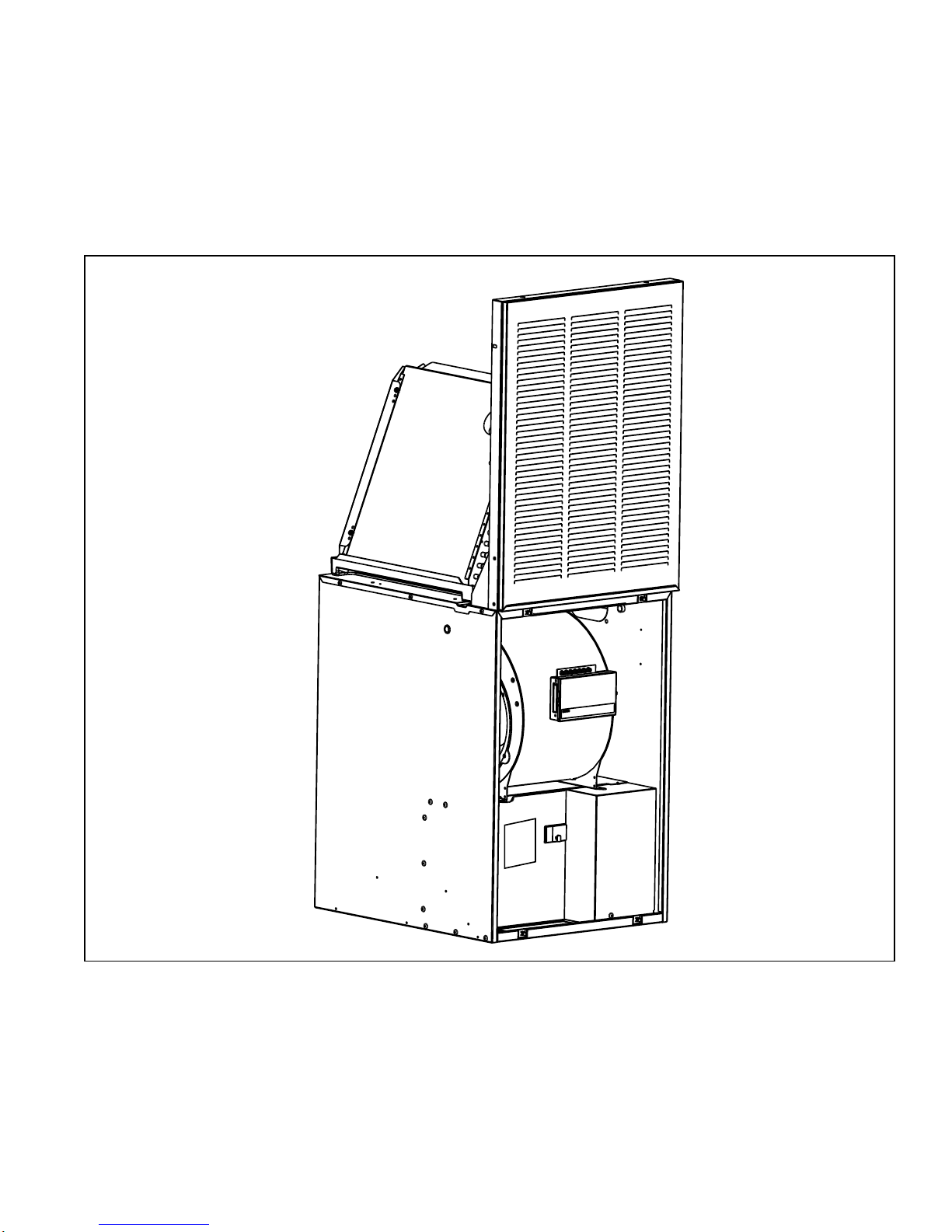
E2 series electric furnaces are approved for use in
mobile/modular homes. The E2 series furnaces are
approved for downflow and upflow installations as free
standing units, or for alcove installations. All furnaces
models are approved for “zero” inch clearance from
combustible materials. For downflow alcove
installations a grille with frame may be attached to the
top of the furnace and all paneling and trim flushed to
it.
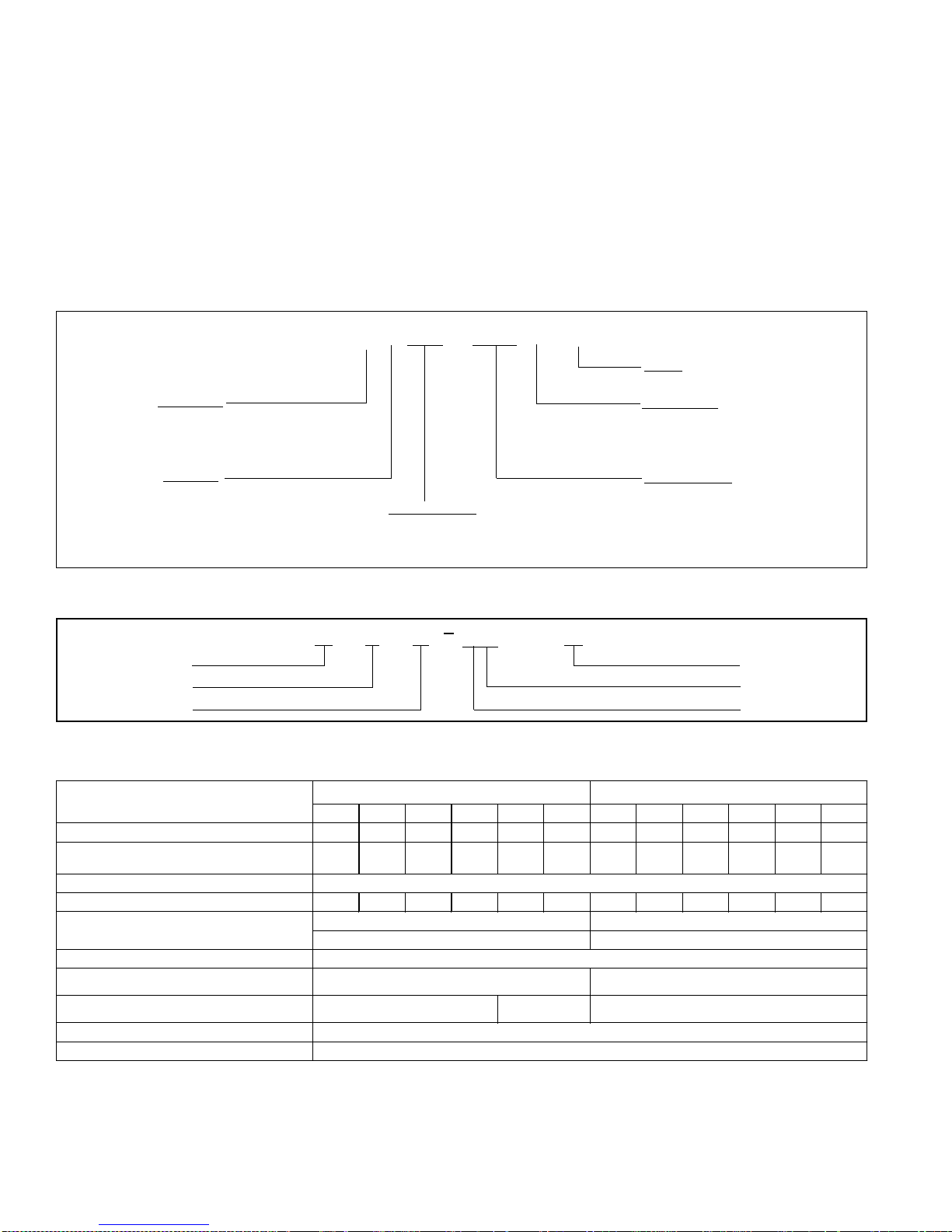
MODEL IDENTIFICATION CODE
E 2 EB - 010 H - A
Product Type
E -Electric Furnace
This installations provides an access door for future
installation of an air conditioning/heat pump coil. All E2
series furnaces are A/C, heat pump adaptable. Refer to
table 2 For optional air conditioner/ heat pump
equipment. The E2 series includes two models: E2EH
and E2EB models. The E2EH models are equipped
with a two speed blower and require the addition of a
replay package for the addition of air conditioning or
heat pump. The E2EB furnaces are equipped with a
multi-speed (4-speed) blower, blower relay, and cabinet
insulation.
Options
A -A/C Ready
Electrical Code
H - 240-1-60
Generation
2 - Second Series
Product Identifier
EH - Heat Only
EB - A/C Blower Equipped
Primary Capacity
010 - 10 kw
012 - 12 kw
015 - 15 kw
017 - 17 kw
020 - 20 kw
023 - 23 kw
SERIAL NUMBER IDENTIFICATION CODE
E
Electric
Design Series
Manufacured Housing
Electric Furnace Models E2EH E2EB
010H 012H 015H 017H 020H 023H 010H 012H 015H 017H 020H 023H
Rated Heating Output, Btuh (see note1)
Watts (T otal kw, Heat ing Elements and
Heating Elements, No. (Total kw) 2 (10. 0) 2 (11.6) 3 (15.0) 3 (16.2) 4 (20.0) 4 (21. 6) 2 (10.0) 2 (11. 6) 3 (15.0) 3 (16.2) 4 (20.0) 4 (21.6)
Blower: Wheel Size 10.5" Dia., 8" Wide 10.5" Dia., 8" Wide
Motor S peeds, H.P. Rat ing, A mps 2 Speed, 1/5 Hp, 2. 0 A mps 4 Speed, 1/3 Hp, 2. 9 A m ps
Test ESP, in. w.c. Max 0.3
Optional Coolin
installed blow er
Opt ional Heat Pump Available with
fac tory installed blow er
Available with factory
Air Filter (St andard) 16" x 20" x 1" ( nominal)
Furnace Dimensions Width - 20" (508 mm ) Height - 29" (737 mm ) ( s ee not e 2) Depth - 24- 1/ 2" ( 623 mm )
Blower) 10.4 12.0 15.4 16.6 20.4 22.0 10.4 12.0 15.4 16.6 20.4 22.0
Supply Voltage 240/208 Volts/60Hz/1-Phase
35,000 41,000 53,000 57,000 70,000 75,000 35,000 41,000 53,000 57,000 70,000 75,000
2.0 - 3.0 ton (see note 3) n/a (see not e 3) 2.0 - 4. 0 t on (s ee not e 4)
E
2
2.0 - 3.0 ton (see note 3) 2.0 - 4. 0 t on (s ee not e 4)
9705
01234
Production Code
Month
Year
1. Heating output rated at listed voltage. For outputs at voltages other than 240V, multiply Btuh rating by the following factors: x 0.92 (230V), x 0.84 (220V), x 0.75 (208V)
2. Height is 56" with return air grille installed, 58" with coil cabinet and 72" with coil cabinet and upflow stand.
3. The factory installed blower for the EH models can be replaced with a multi-speed blower allowing the units to accept up to 4 or 5 tons of air conditioning or heat pump.
4. The factory installed blower for the EB models can be replaced with a multi-speed blower allowing the units to accept up to 5 tons of air conditioning or heat pump.
4 E2 Service Manual
Table 1. Unit Specifications
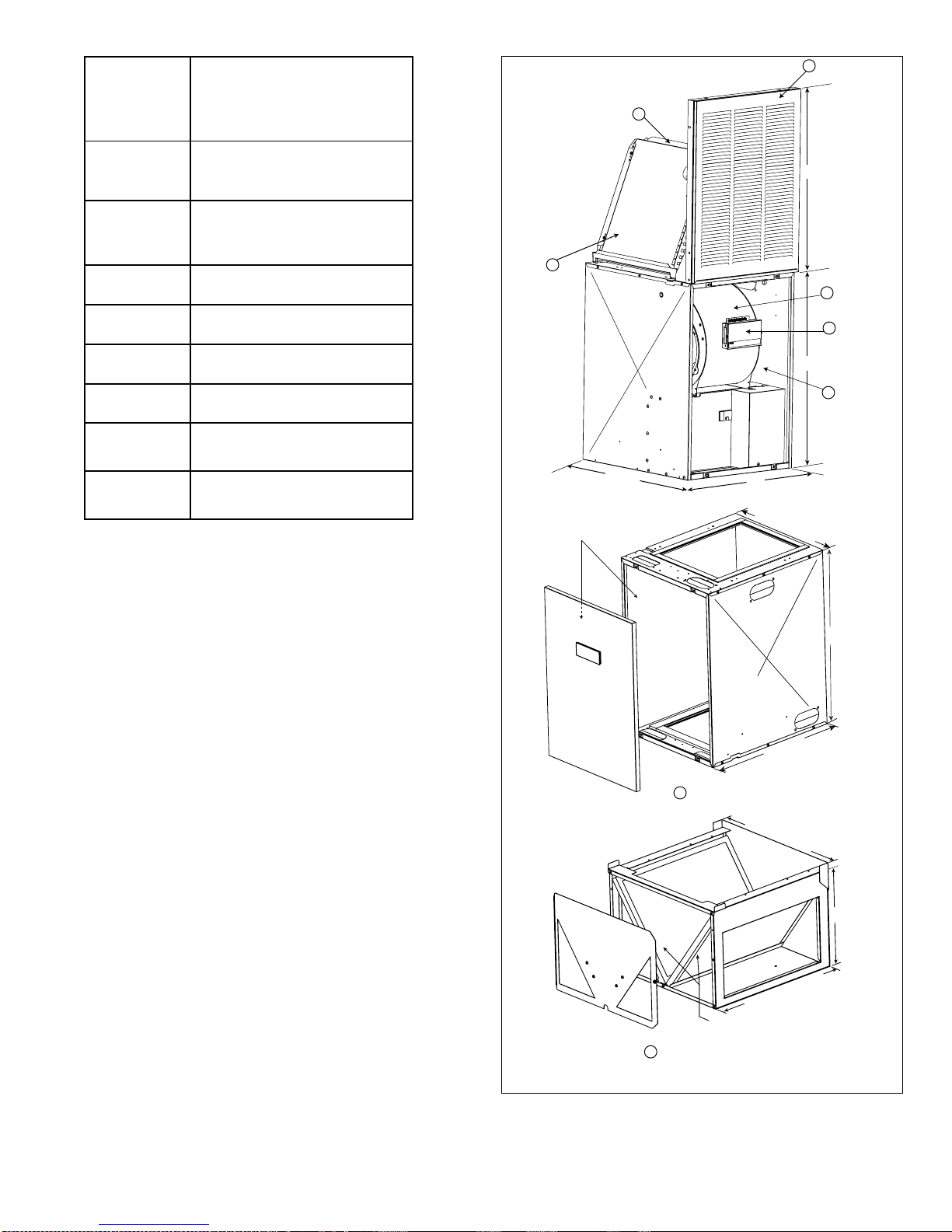
Item
8
Number
(See Fig. 1)
1 4-Sp eed B lower
4 T on - S ee Notes: 1 & 5
5 T on - S ee Note: 1
2 A.C./H.P. Relay Control Box
(not r eq’d on E2EB m odels )
See Note: 1
3 Cabinet I ns ulation Kit
See Not es : 1 & 5
4 "A "-Coil Convers ion K it
See Note: 2
5 Coil Cabinet
See Note: 3
6 Upfl ow S tand
See Note: 4
7 A/C and H/ P Indoor Coils
8 Retu r n A i r Grille and Frame
Assembly
No tes :
1) For A/C and H/P use.
2) Includes co il filters.
3) For upflow or downflow installations.
4) For upflow A/C or H/P installations (includes
on e f i lter; use f ilter from furnace t o complet e
filtering syst em in thi s acces sory).
5) Standard in EB models.
Descrip ti on
4
Cabinet
Insulation
23 3/4”
(603 mm)
7
27” (686 mm)
1
2
29” (737 mm)
3
20”
(508 mm)
20” (508 mm)
29” (737 mm)
Table 2. Optional Air Conditioning and
Heat Pump Equipment
Sequence of operation
With the circuit breakers in the on position and the
blower switch in the auto position. One half of the
control heating element and motor electrical circuit is
activated. When the contacts close in the wall
thermostat 24 volts is supplied by the 240/24 volt
transformer to the sequencer heater. This heats a bi metal in the sequencer which closes a set of contacts
and completes the circuit to the no.1 element and the
blower motor. As the heater continues to build up heat,
the bi-metal closes the remaining circuits to other
elements, until all elements are on. The “off” cycle is
reverse of the “on” cycle the blower and no.1 element
are first on and the last to be de-energized.
23 3/4”
(603 mm)
5
Coil Cabinet
20” (508 mm)
14” (357 mm)
23 3/4” (603 mm)
Filters (one obtained
from furnace)
6
Upflow Stand
NOTE: See Table 2 for descriptions and notes
Figure 1. Optional Accessories
5 E2 Service Manual
Sequencer (Figure 2)
In general all sequencers operate the same way. In
some applications one sequencer may be sufficient
(10 and 12 kw models) in other applications. One two
or more sequencers may be required.
Important: Sequencers should never be mixed. If
different brands of sequencer are used and their timing
may be different.
Testing Sequencer
1. Shut off the power supply to the furnace, there
could be two circuits. Be sure both "A" and "B"
circuits are de-energized.
a. Remove all wires from the sequencer (making
note of wire color and terminal location). The
bi-metal heater portion of the sequencer will be
unmarked and at the bottom, closest to the
mounting plate. The switching portion will be
marked M1 through M8 depending on the
number of switches. Refer to unit wiring
diagram.
b. With an ohmmeter, test for continuity across
the bi-metal heater terminals. There should be
70 to 90 ohms of resistance. If the meter reads
no continuity, the bi-metal heater is open and
must be replaced. The OHMS value should be
70 to 90 across the bi-metal.
Figure 2. Sequencer
c. With an ohmeter check all switches in the
sequencer. They are labled M1-M2, M3M4...refer to Figure 2. All of the switches should
be open and have no continuity.
2. With all power on to furnace, and thermostat
contacts closed: using a voltmeter (set scale for
220 vac.) On contact terminals of sequencer,
check each set of terminals of sequencer, check
each set individually. If you read voltage, contacts
are open. If you do not read voltage, contacts are
closed. Allow a maximum time (110 seconds) for
heater to close contacts. If any of the contacts
remain open after three minutes the sequencer is
defective and should be replaced.
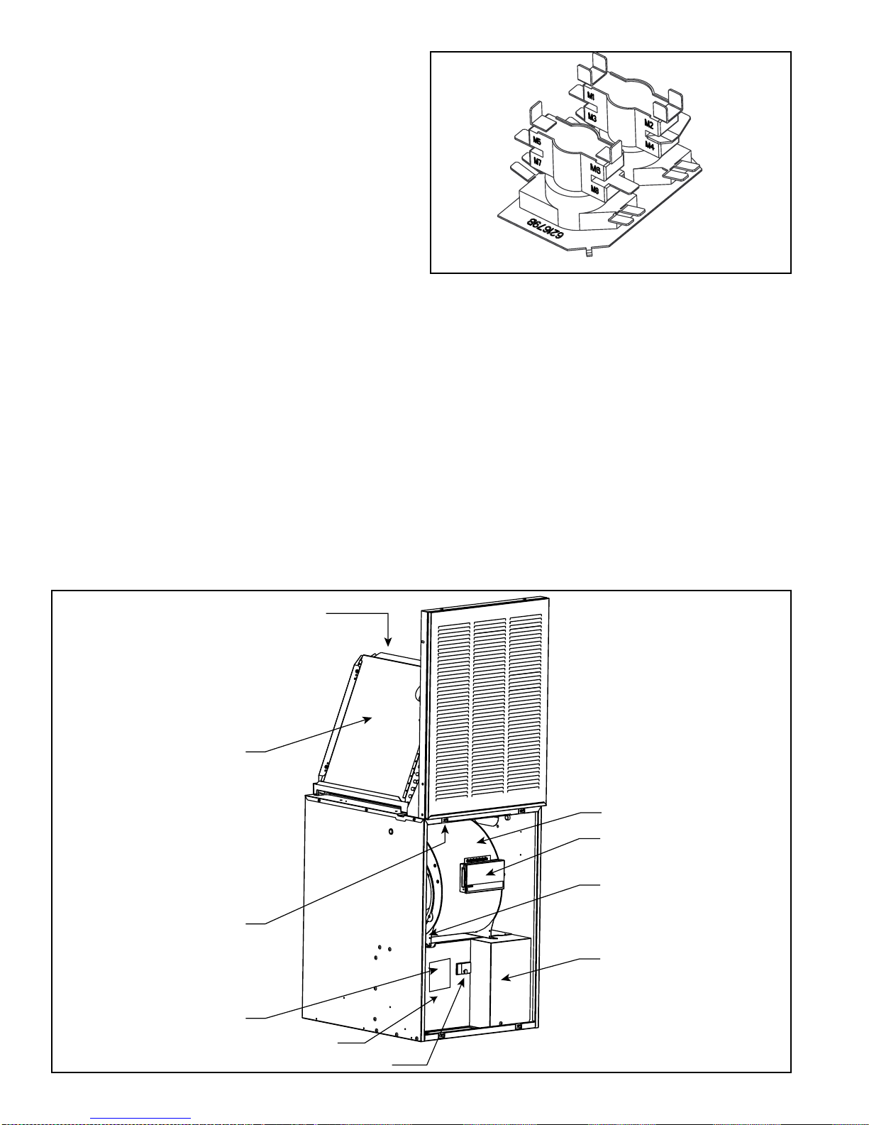
Indoor Coil
(optional)
Coil Air Filters
(used with indoor coil)
Furnace Air Filter
(NOT used with indoor coil
and coil air filters)
Data Label
Blower
A/C or H/P Relay Box (optional)
Blower Selector Switch
(next to blower)
Control Panel Cover
(right)
Control Panel Cover (left)
6 E2 Service Manual
Circuit Breakers
Refer to unit wiring diagram section for wiring of
sequencer for each model furnace.
Control Transformer (Figure 3)
All E2 furnaces are equipped with a 30 VA, 240/208
vac primary, 24 vac secondary transformer.
The function of the transformer is to supply the 24
volts for the low voltage circuit which activates the
controls. Note: never replace a transformer with one
of less VA rating: however a higher rated transformer
can replace a lower rated unit. Example: unit has 30
VA replacement can be 40 VA.
Checking Transformer
1. Using a voltmeter, test power supply on the primary
leads of the transformer- must be 240 v +/- 10%.
If less than 226 vac switch black and blue primary
leads.
2. Remove wires from the secondary side of the
transformer. Or find the area where the wires
terminate and remove from component.
3. Use the voltmeter check the output of the
transformer, it should read 22 to 28 volts. If not,
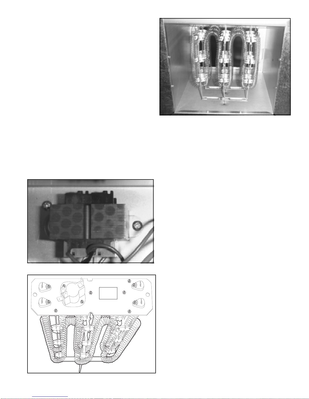
Figure 5. Heating Elements in Furnace
then the transformer is nonfunctional and should
be replaced. Observe the transformer there should
be no distortion in shape, oil residue or odor. If any
of these symptoms exist replace the transformer.
Heating Elements (Figures 4 & 5)
The heating elements used are of modular design
consisting of helical-coiled nichrome resistance wire.
An insulated wire formed assembly supports the heating
elements. All elements are rated at 240 volts. Each
element is individually controlled by a switch of the
sequencing system and is protected by a limit switch.
Figure 3. Transformer
The function of the heating element, of course, is to
heat the air passed across them by the blower system.
Testing Heating Elements (Ohmmeter)
1. Shut off all electric supply to furnace
2. Remove all wires from terminals of heating coils
3. Using the ohmmeter test from terminal to terminal
of the coil-must show continuity-if not replace
element assembly.
4. Using the ohmmeter test from heating element
terminal to ground wire in the control panel, there
should be no continuity. If there is the coil is
grounded and must be replaced.
Caution: Heating elements must always be replaced
by an identical kW replacement. Substitution by higher
kW’s or elements of a different design may result in
unsafe operation of the furnace. Lower kW rated
elements will reduce output and may result in
unsatisfactory operation of the appliance. Refer to
element rating labels and furnace wiring diagrams.
Figure 4. Heating Element
7 E2 Service Manual
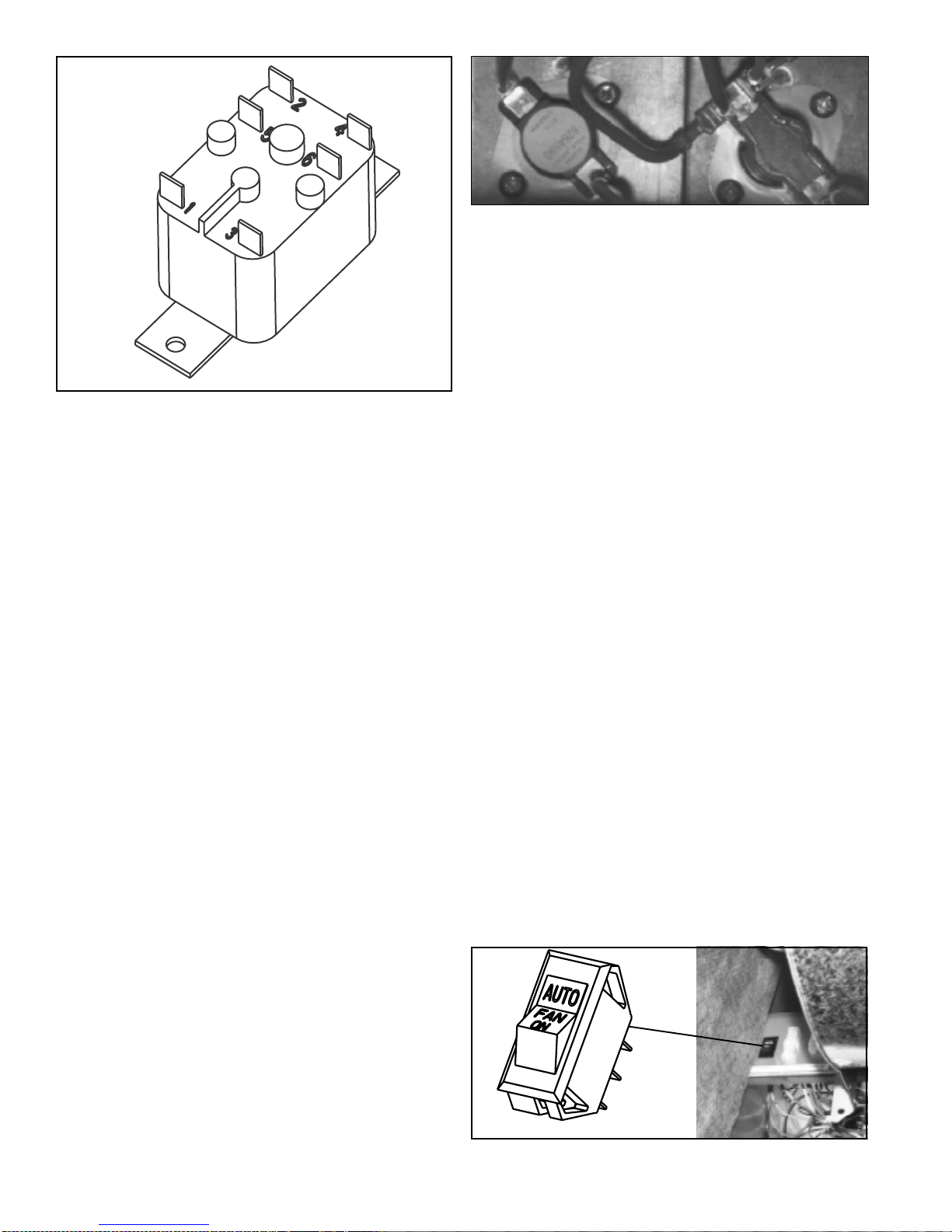
Figure 6. Cooling Relay
Cooling Relay (Figure 6)
The E2EB has a factory installed cooling relay. The
cooling relay operates the air circulator at the high
speed when the relay is energized. The relay is
energized by the low voltage circuit by the g terminal
of the thermostat. At the same time it breaks the circuit
to the heating speed of the air circulator. the cooling
relay has one set of normally closed and one set of
normally open contacts.
Testing Cooling Relay
1. Turn off all power supply to furnace.
a. Remove all wires from cooling relay.
b. Using ohmmeter, test from terminal no. 1 to
terminal no.3 the coil should have resistance of
around 76 ohms. If there is no continuity, the
relay has a open coil and must be replaced.
c. Using ohmmeter, test from terminal no.5 to
terminal no. 6 there should be continuity, if no
continuity is shown relay is defective and must
be replaced.
d. Replace wires on terminal no.1 and 3 restore
power supply.
e. Energize relay by positioning the fan switch on
the thermostat to the fan position. The relay
should click.
f. Using ohmmeter, test terminals 2 and 4 there
should be continuity. If no continuity relay is
defective.
g. Turn off all power to furnace, reconnect all
wires to relay and restore power.
Figure 7. Limits in furnace
The limit device is a safety which can be compared to
a fuse or a breaker in a electrical circuit. The function
of the limit switch is to open the electrical circuit to the
heating elements if over heating should occur. This
could be caused by air circulator failure, dirty filters,
lack of return air, restricted ducts, etc. All limit switches
used are of the automatic reset type. On cool down
they will automatically reset.
Testing the Limit Switches
1. Shut off all electric supply to furnace.
2. Allow enough time for limit to cool down ( 5 to 10
minutes)
3. Remove wires from terminals of limit switches.
Note: all limit switches will be located on the
heating element rack face plate with red wires
attached to them.
4. Using the ohmmeter, test from terminal to terminal
continuity must be read. If no continuity is read
after cool down time, switch is defective and should
be replaced.
Caution: Limit switches must always be replaced by
their identical replacement part, i.e. Same setting, style
limits on the E2 series are either single or double pole
type thermo disc. Under no circumstance should a
limit of a higher setting or of a different type be installed.
Replacement with a lower setting limit may result
cycling of the control and insufficient heat output.
Air Circulation Switch
The air circulation switch is a manual rocker type
switch, single pole double throw, the switch when in the
“auto” position, allows the blower to be activated by the
Limit switches
A limit switch is a heat sensing device utilizing a bimetal disc to open a set of normally, closed contacts.
8 E2 Service Manual
Figure 8. Air Circulation Switch
sequencer. The blower will run during the heating
cycle of the furnace. When the switch is in the “fan”
position the blower will run continuously. See Figure
8 for air circulation switch.
1
Black
* Yellow on E2EH 015, 017, 020, 023
Figure 9. Fan Switch Shematic
2
Red*
3
Yellow
Checking the Air Circulator Selector Switch
To check the air circulator switch shut of all power to the
furnace. Remove wires from air circulator selector
switch terminals. Check continuity of terminals with the
switch in “on” and “auto” position. See Figure 9 for fan
switch schematic.
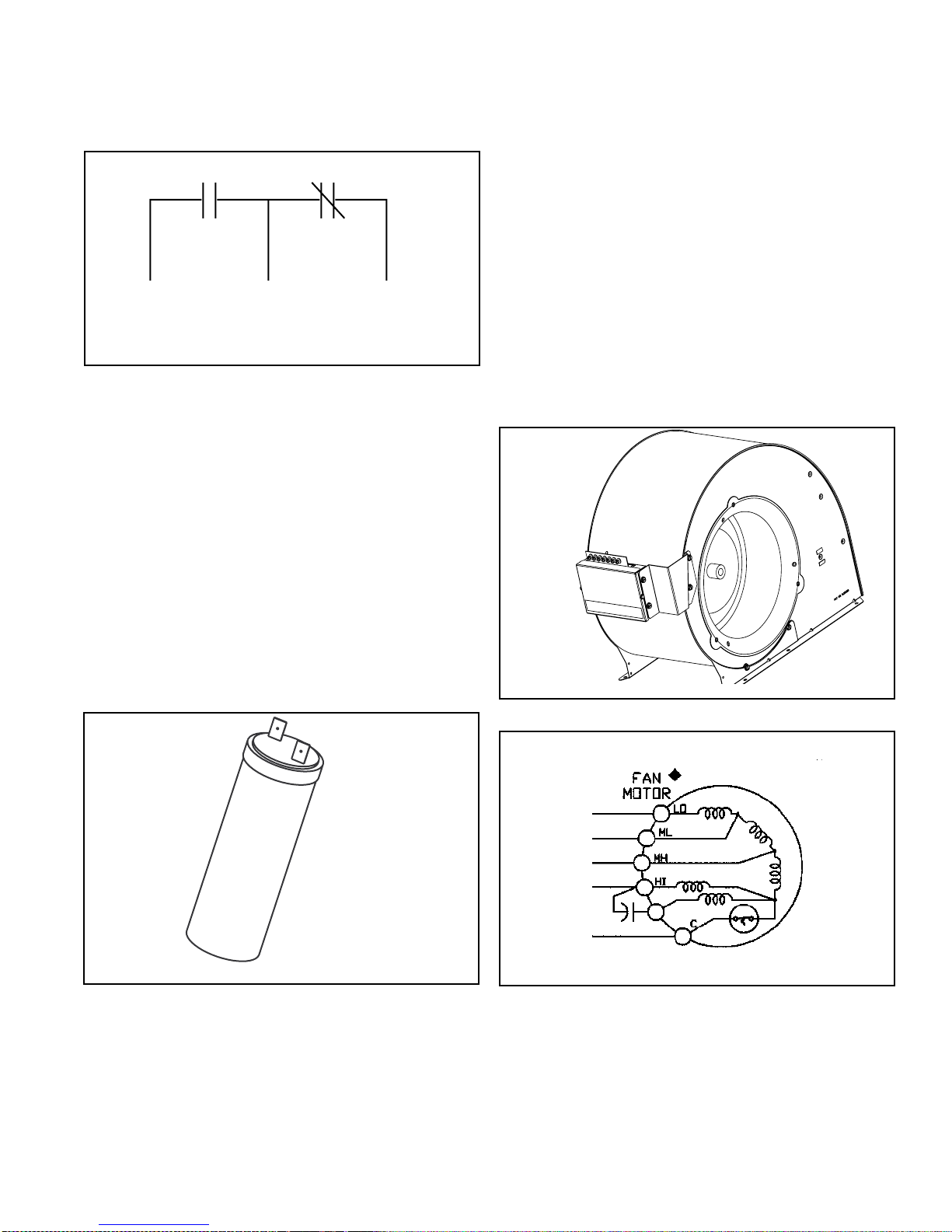
Capacitor(See Figure 10):
1. Shut off the electrical supply to the unit.
2. Disconnect he electrical leads to the capacitor.
3. Discharge the capacitor using a 1500 ohm resister.
4. Check the capacitor using a capacitor tester.
Blower Motor (See Figure 11):
1. Shut power off to the furnace.
2. Disconnect the electrical motor leads.
3. Using an ohmmeter, check for continuity from each
terminal to the shell of the motor, if there is continuity,
the motor is grounded and should be replaced.
4. Using the ohmmeter, check the resistance across
the motor leads. See diagrams below. Note: the
higher the speed the lower the resistance of the
motor winding.
Air Circulator Motor
The circulator motor and blower wheel combination
move air across the heating elements to supply the
duct system with warm air.
To check the motor, be certain the capacitor is
functional.
Figure 10. Capacitor
Figure 11. Blower
Figure 12. Motor Schematic
9 E2 Service Manual
 Loading...