

Nordyne CMF2 80-PG Convertible, CMF2 80-PO Convertible Owner's Manual
Counterflow Gas or Oil Heating Appliance
Owners Manual/Installation Instructions
CMF2 80-PG Convertible (65, 75, and 85 KBTU/H Inputs),
CMF2 80-PO Convertible (65, 75, and 85 KBTU/H Inputs)
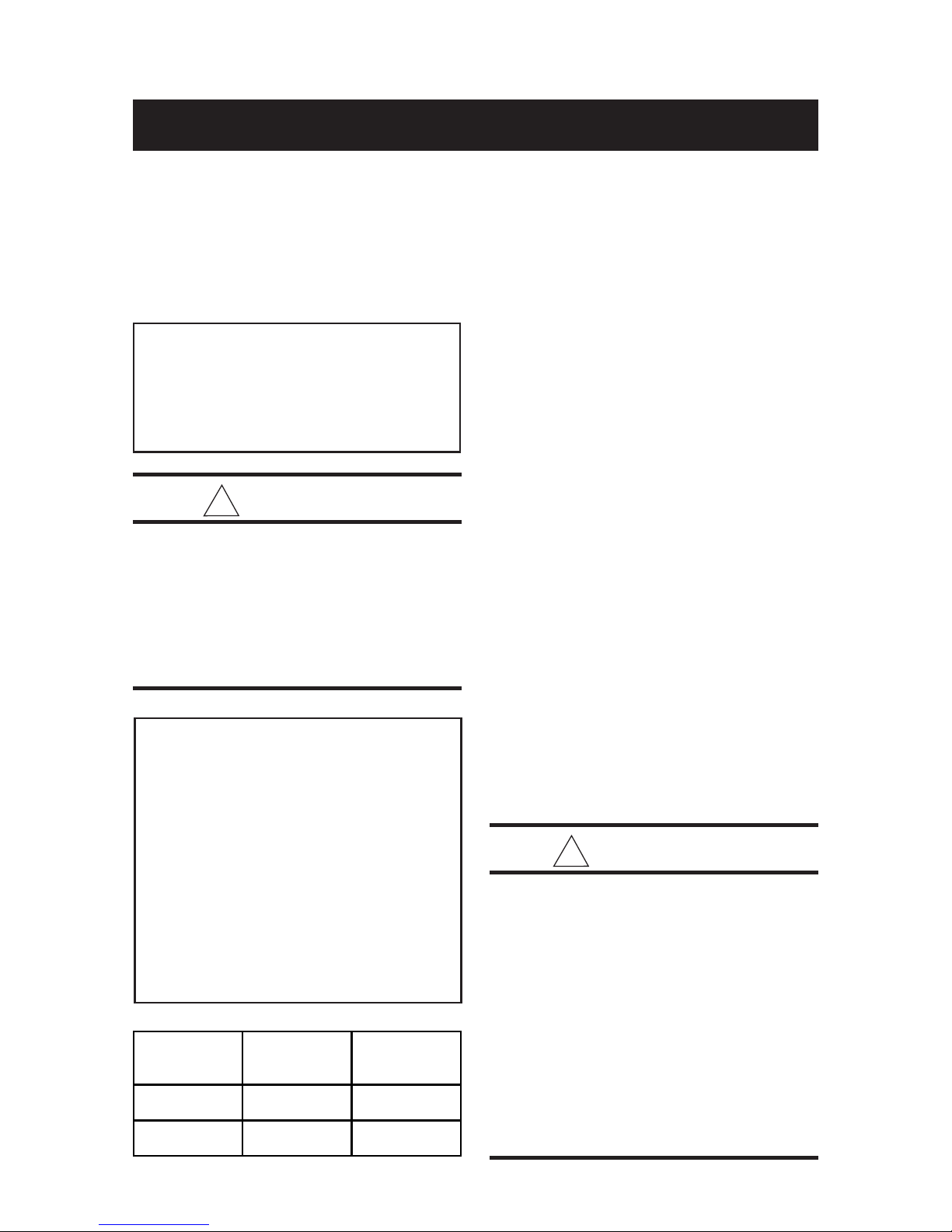
Read all instructions carefully before beginning the installation. Read all labels and tags
on the furnace carefully and follow all precautions outlined on those labels and tags.
GENERAL
FOR YOUR SAFETY
Do not store or use gasoline or other
flammable vapors and liquids in the
vicinity of this or any other appliance.
!
WARNING:
Improper installation, alteration, service or maintenance can cause injury
or property damage. Refer to this
manual for assistance or consult a
qualified installer, service agency, or
the gas supplier for additional information.
FOR YOUR SAFETY
WHAT TO DO IF YOU
SMELL GAS
• Do not try to light any appliance.
• Do not touch any electric switch; do not
use any phone in your building.
• Immediately call your gas supplier from
a neighbor’s phone. Follow the gas
supplier’s instructions.
• If you cannot reach your gas supplier,
call the fire department.
Rated CMF2-PG CMF2-PO
BTUH 80 CONV. 80 CONV.
Input 75,000 75,000
Output 56,000 60,000
CMF2 furnaces are high quality, direct vent
furnaces used for manufactured housing, recreational vehicle, and residential
These furnaces are offered in either power gas
(designated by PG) or power oil (designated by
PO) models. The power gas models are designed for operation with either natural or propane (LP) gas.
The CMF2 series is convertible from power oil
to power gas, and vice versa. Furthermore, the
firing rate of the CMF2 80 Convertible Series
can be changed using a certified NORDYNE
conversion kit field-installed by a qualified service
technician. Refer to the “Firing Rate Conversion”
section later in these instructions for more
information on the firing rate change.
These furnaces are certified to the UL307
standards (UL 307A for oil models; UL 307B for
gas models), and can be installed in a variety of
applications, as shown in Table 1. This furnace
is not to be used for temporary heating of
buildings or structures under construction.
!
WARNING:
This furnace must be installed by a qualified installing agency and in accordance
with applicable local codes and ordinances that govern this type of equipment. Failure to properly install the furnace, base assembly, and venting system as described herein may damage the
equipment and/or the home, can create a
fire or asphyxiation hazard, violates U.S.
listing requirements, and will void the
warranty. This furnace is NOT approved
for installation with split system air conditioning. Use a NORDYNE packaged air
conditioning system.
†
applications.

INSTALLATION REQUIREMENTS ........................................................................................... 3
Equipment Check .................................................................................................................3
Requirements and Codes .................................................................................................... 3
Important Note ..................................................................................................................... 3
Combustion Air and Ventilation Requirements .................................................................... 4
Venting Requirements – Manufactured Housing Installations ........................................... 4
Venting Requirements – Residential Installations ............................................................... 5
Unit Location and Clearance Requirements ....................................................................... 7
UNIT INSTALLATION ................................................................................................................ 7
MA-200 Base Installation ..................................................................................................... 8
MA-100 Universal Base Installation .................................................................................... 8
Combustion Air Duct/Pipe Installation ................................................................................. 8
Damper Installation .............................................................................................................. 9
Installation of Furnace onto the MA-200 Base .................................................................... 9
Installation of Furnace onto the MA-100 Base .................................................................... 9
CB-200 Cottage Base Installation ....................................................................................... 9
Closet Installation of the Furnace ...................................................................................... 10
Chimney Installation ........................................................................................................... 13
Installation of Ventilaire III or IV Air Quality Package ........................................................ 13
FUEL CONNECTIONS ............................................................................................................. 13
Oil Piping Installation – PO Series Only ............................................................................ 14
Fuel Line Hook-Up ............................................................................................................. 14
HookUp Procedure ............................................................................................................ 14
How to Eliminate Air Leaks ................................................................................................ 16
Fuel Oil Type ...................................................................................................................... 16
ELECTRICAL WIRING ............................................................................................................. 16
General ............................................................................................................................... 16
Line Voltage Requirements ................................................................................................ 16
Line Voltage Connections .................................................................................................. 16
Room Thermostat Requirements ...................................................................................... 16
Room Thermostat Connections ........................................................................................ 17
FAN AND LIMIT CONTROLS .................................................................................................. 17
Fan Limit Switch ................................................................................................................. 17
Supply Air Limit Switch ....................................................................................................... 17
Auxiliary Limit ..................................................................................................................... 17
MAINTENANCE ........................................................................................................................ 18
Air Filters ....................................................................................................................
Combustion Air and Venting System ................................................................................. 18
LIGHTING AND OPERATING INSTRUCTIONS FOR CMF2 PG DIRECT IGNITION GAS
BURNERS ......................................................................................................................... 18
Operating Instructions for PG Direct Ignition Burner ....................................................... 18
To Turn Off Gas to the Appliance ..................................................................................... 18
Checking the Input of the Furnace .................................................................................... 19
Measuring the inlet Gas and Manifold Pressures ............................................................ 19
Gas Burner Controls ......................................................................................................... 20
Natural Gas to LP Conversion .......................................................................................... 20
Adjusting the Burner .......................................................................................................... 21
LIGHTING AND OPERATING INSTRUCTIONS FOR CMF2 PO OIL BURNERS .............. 22
Start-Up Procedure ........................................................................................................... 22
Air-Bleed Procedure - Single Pipe Installation ................................................................... 22
Oil Burner Shutdown Procedure ....................................................................................... 22
Flame Adjustment .............................................................................................................. 22
Electrode Setting ................................................................................................................ 22
SWITCHING FROM INTERRUPTED TO INTERMITTENT IGNITION CONTROL ............. 22
FIRING RATE CONVERSION .................................................................................................. 23
FURNACE OPERATING SEQUENCE .................................................................................... 23
ADJUSTING HEAT DISTRIBUTION ....................................................................................... 24
SERVICE GUIDE FOR FURNACES WITH PGB POWER BURNER WITH DIRECT
IGNITION-GAS GUN ........................................................................................................ 24
TROUBLESHOOTING ............................................................................................................. 26
TABLE OF CONTENTS
........ 18
!
WARNING:
Do not use this appliance if any part has
been submerged under water. Immediately call a qualified service technician to
inspect the appliance and to replace any
part of the control system and any gas
control that has been submerged under
water.
Installations (Manufactured Home Sites,
Communities, and Set-ups), ANSI 225.1.
All residential installations (Refer to Table 1)
must conform with these instructions, all
applicable local building codes, ANSI Z223.1/
NFPA 54 (National Fuel Gas Code), ANSI/
NFPA 31 (Installation of Oil-Burning Equipment),
ANSI/NFPA70 (National Electrical Code), and
NFPA 211 (Chimneys, Fireplaces, Vents, and
Solid Fuel-Burning Appliances).
INSTALLATION REQUIREMENTS
Equipment Check
All units are securely packaged at the time of
shipment and should be carefully inspected
upon arrival for damage. Claims for damages
(apparent or concealed), shortage in shipment,
or nondelivery should be filed immediately against
the carrier by the consignee. The carrier is
responsible for making prompt inspection of
damage and for a thorough investigation of
each claim. The manufacturer will not accept
claims for transportation damage.
Requirements and Codes:
Installer shall be familiar with and comply with all
codes and regulations and applicable to the
installation of these heating appliances and
related equipment.
All manufactured housing installations must
conform with these instructions, all applicable
local codes, ANSI Z223.1/NFPA 54 (National
Fuel Gas Code), ANSI/NFPA 31 (Installation of
Oil Burning Equipment), ANSI/NFPA 70
(National Electrical Code), the Manufactured
Home Construction and Safety Standard, Title
24 CFR, part 3280, or when this standard is not
applicable, the standard for Manufactured Home
The National Fuel Gas Code is available by
writing:
American National Standards
Institute, Inc.
1430 Broadway
New York, NY 10018
NFPA publications are available by writing:
National Fire Protection Association
Batterymarch Park
Quincy, ME 02269
IMPORTANT NOTE
The Commonwealth of Massachusetts requires compliance with regulation 248 CMR
4.00 and 5.00 for installation of through – the
– wall vented gas appliances as follows:
(a) For direct-vent appliances, mechanical-
vent heating appliances or domestic hot
water equipment, where the bottom of the
vent terminal and the air intake is installed
below four feet above grade the following
requirements must be satisfied:
1. If there is not one already present, on
each floor level where there are
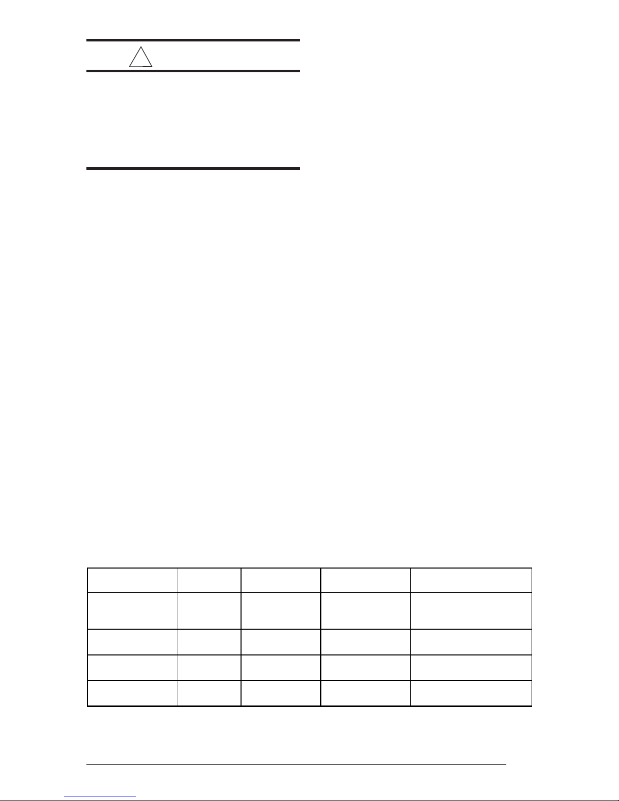
Type of Ducted Direct Vent Furnace Flue Products
Installation Applica tion System Requir ed Bas e Us ed Exhaus te d By
Manufactured
Housing or Yes Yes
Recreational Vehicle
Residential
Residential
Residential
†Residential is only defined as a s ingle-story non-manufac tured housing installation.
*Refer to the "Venting Requirements " section later in these instructions for more details on properly v enting this appliance
through an existing chimney.
†
†
†
Yes
Yes
No
Yes
Yes
No
Table 1
MA-100 or MA-200
Universal Base
MA-100 or MA-200 NORDYN E SRJ Roofjack or
Universal Base an Existing Chimney*
CB-200A Cottage NORDYNE SRJ Roofjack or
Base an Existing Chimney*
CB-200A Cottage NORDYNE SRJ Roofjack or
Base an Existing Chimney*
NORDYNE SRJ
Roofjack Only
3

bedroom(s), a carbon monoxide detector and alarm shall be placed in the
living area outside the bedroom(s).
The carbon monoxide detector shall
comply with NFPA 720 (2005 Edition).
2. A carbon monoxide detector shall be
located in the room that houses the
appliance or equipment and shall:
a. Be powered by the same electrical
circuit as the appliance or equipment such that only one service
switch services both the appliance
and the carbon monoxide detector;
b. Have battery back-up power;
c. Meet ANSI/UL 2034 Standards and
comply with NFPA 720 (2005 Edi-
tion); and
d. Have been approved and listed by a
Nationally Recognized Testing Labo-
ratory as recognized under 527
CMR.
3. A Product-approved vent terminal must
be used, and if applicable, a Productapproved air intake must be used.
Installation shall be in strict compliance
with the manufacturer’s instructions. A
copy of the installation instructions shall
remain with the appliance or equipment
at the completion of the installation.
b. Be either hard-wired or battery pow-
ered or both; and
c. Shall comply with NFPA 720 (2005
Edition).
3. A Product-approved vent terminal must
be used, and if applicable, a Productapproved air intake must be used.
Installation shall be in strict compliance
with the manufacturer’s instructions. A
copy of the installation instructions shall
remain with the appliance or equipment
at the completion of the installation.
Combustion Air and Ventilation
Requirements
Provisions for adequate combustion air and
ventilation air must be in accordance with the
ANSI Z223.1/NFPA 54, (National Fuel Gas
Code), ANSI/NFPA 31 (Installation of Oil Burning
Equipment), and all applicable local codes.
Depending upon the type of installation (See
Table 1), the CMF2 furnace can draw the
combustion air either from outside the home
(direct vent) or from the space being conditioned.
A direct vent system is one in which the flue
products are exhausted to and the combustion
air is drawn from outside the house. A direct
vent system can also be referred to as a sealed
combustion system.
4. A metal or plastic identification plate
shall be mounted at the exterior of the
building, four feet directly above the
location of vent terminal. The plate shall
be of sufficient size to be easily read
from a distance of eight feet away, and
read “Gas Vent Directly Below”.
(b) For direct-vent appliances, mechanical-
vent heating appliances or domestic hot
water equipment where the bottom of the
vent terminal and the air intake is installed
above four feet above grade the following
requirements must be satisfied:
1. If there is not one already present, on
each floor level where there are
bedroom(s), a carbon monoxide detector and alarm shall be placed in the
living area outside the bedroom(s).
The carbon monoxide detector shall
comply with NFPA 720 (2005 Edition).
2. A carbon monoxide detector shall:
a. Be located in the room that houses
the appliance or equipment;
4
For direct vent applications either the combustion
air duct provided with the MA Series base kit or
the direct vent kit can be used. The direct vent
kit must be ordered separately. Only for a
special CB-200A cottage base installation can
the CMF2 draw the combustion air from the
conditioned space. The CB-200A cottage base
kit must be ordered separately. Refer to the
replacement parts listing provided with the
furnace to order the direct vent kit or the cottage
base kit. Follow the instructions provided with
the kits for proper installation.
When unsure about combustion air supply
availability, a direct vent system should be
used. For small rooms, confined spaces, tight
construction or similar situations in which the
combustion air requirements of the furnace
might not be met, a direct vent system must be
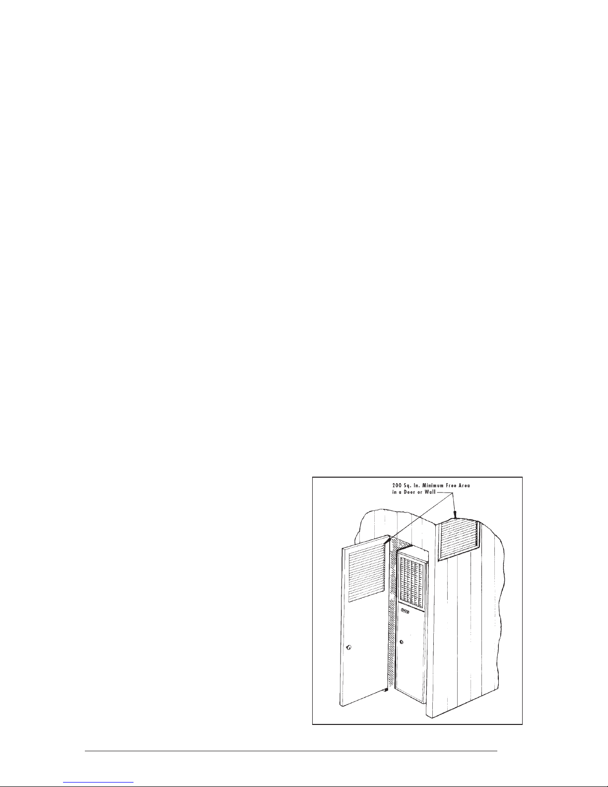
used. The air openings in the door of the unit and
the warm air registers from the ductwork or
base must not be restricted.
Combustion air must not be drawn from a
contaminated atmosphere. Excessive
exposure to contaminated combustion air will
result in safety and performance related
problems. Some examples of chemical
contaminants are chlorine, fluorine, and sulfur,
which can be found in a wide variety of some
common commercial and household products.
The installation of the furnace must allow for an
adequate supply of combustion air. The
combustion air opening of the furnace must be
designed and located to prevent blockage by
snow.
When drawing the combustion air from
underneath the home, ensure that a vent or duct
of at least 18 square inches of free area is
provided from outside. Check to ensure that the
combustion air opening is unobstructed. When
using the combustion air duct, ensure that it
extends through the floor. When using the direct
vent kit, the combustion air opening must be
located in the same pressure zone as the flue
exit of the roof jack or chimney. Refer to the
instructions provided with the direct vent kit for
more information.
!
WARNING:
When venting through a chimney, check
the chimney for soot, leaks, obstructions, and proper installation.
The materials used to construct the venting
system must be capable of withstanding
exposure to temperatures of at least 700 degrees
F. The existing chimney servicing this furnace
must be vertical. Horizontal distances to an
existing chimney must be as short as possible,
and the connecting pipe must slope upward to
the chimney at not less than a 45 degree angle.
The total length of the sloping pipe must not
exceed 6 feet. The venting system must have
no obstructions or sharp bends where soot and
other foreign matter can accumulate.
If an inspection determines that the chimney is
obstructed, the chimney must be cleaned.
Furthermore, the connecting flue pipe must be
cleaned or replaced.
Venting Requirements — Manufactured
Housing Installations
For all manufactured housing applications, the
CMF2 furnace must be vented using the SRJ
series roofjack. The instructions for selecting
the proper roofjack for your installation are
detailed later in these instructions.
Venting Requirements — Residential
Installations
!
WARNING:
This furnace is not to be connected to a
chimney flue serving a separate appliance designed to burn solid fuel.
For residential applications (Refer to Table 1),
the CMF2 furnace may be vented through the
SRJ series roofjack or through an existing
chimney. If the SRJ roofjack is to be used, then
the instructions for selecting the proper roofjack
for your installation are detailed later in these
instructions. If venting through an existing
chimney, then the venting system used must be
in accordance with these instructions, all
applicable local building codes, ANSI Z223.1/
NFPA 54 (National Fuel Gas Code), ANSI/
NFPA 31 (Installation of Oil-Burning Equipment),
and NFPA 211 (Chimneys, Fireplaces, Vents,
and Solid Fuel-Burning Appliances).
For ONLY a CMF2 power oil furnace installation
vented into an existing chimney, a barometric
damper can be installed at the vent connection
of the furnace to regulate the draft. The barometric
damper must be properly installed per the
manufacturer’s instructions. Refer to all
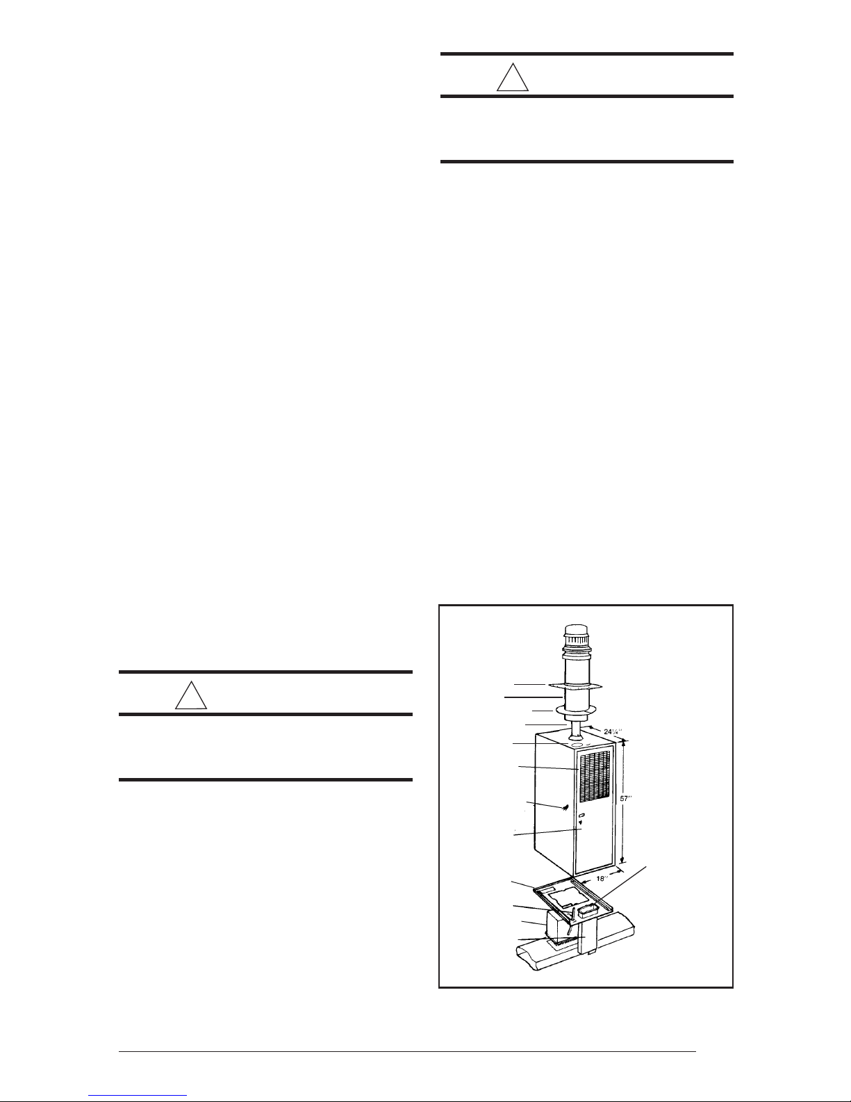
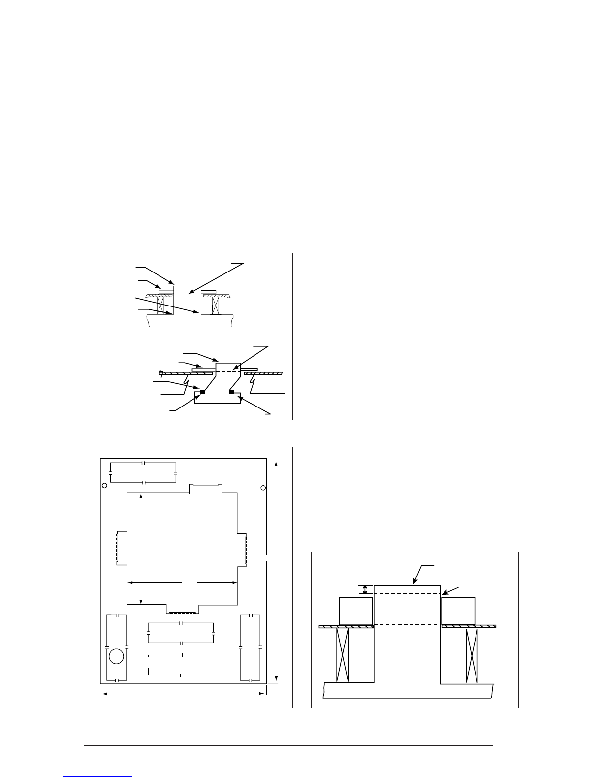
Flashing
Barrel
Ceiling Plate
Ventilation
Knock-Out
Return Air
Grille and
Filter
Power Supply
Connection
Access
Door
Base Pan
Fuel Line
Feeder Duct
Combustion
Air Duct
Vent
ROOF JACK
ASSEMBLY
FURNACE
ASSEMBLY
Combustion Air
Adapter (Not Shown)
is to be Installed
Over Combustion
Air Duct
DUCT
CONNECTOR
Figure 1. Typical Furnace Installation for
Manufactured Housing Applications
5
applicable codes to determine whether or not a
barometric damper can be used for your CMF2
power oil furnace installation. The barometric
damper used must be installed such that air
from the conditioned space can only enter the
flue passageway. Do not use a double acting
barometric damper. All flue pipe joints should be
fastened with sheet metal screws for rigidity.
The chimney height, required draft, and number
of appliances served by the chimney must be
in accordance with all applicable codes. To
prevent down draft, the chimney should extend
at least two feet above the peak of the roof.
Closet Alcove
ALL MODELS Ins ta llation Installation
Sides 0" 0"
Back 0" 0"
Front 6"** 18"
Top 17" 17"
Vent 6" 6"
Duct within 3' from Furnace 1/4" 1/4"
Plenum 1" 1"
Roof Jack Barrel 0" 0"
** See Item K in the "Closet Installation of
Furnace" section later in these instructions for clearance less than 6".
Table 2. Minimum Clearances
to Adjacent Materials
It is recommended that the furnace flue serve
no other appliances. When the chimney serves
only the furnace, the flue area must be sized
according to all applicable codes. The minimum
internal area of the flue must be equal to at least
the area of the furnace flue exit.
When two or more appliances must vent through
a common flue, the area of the common flue
should be sized in accordance with all applicable
codes.
When an existing furnace is removed or replaced
in a venting system, then the venting system
may not be properly sized to vent the attached
appliances. The venting system must be
checked to ensure proper venting. Improperly
sized venting systems can result in the formation
of condensate, leakage, spillage, etcetera.
Refer to the ANSI Z223.1/NFPA 54, (National
Fuel Gas Code), and ANSI/NFPA 31( Installation
of Oil Burning Equipment) for correcting any
improperly operating venting system.
The following steps shall be followed with each
appliance connected to the venting system
placed in operation, while any other appliances
connected to the venting system are not in
operation:
(a) Seal any unused openings in the venting
system.
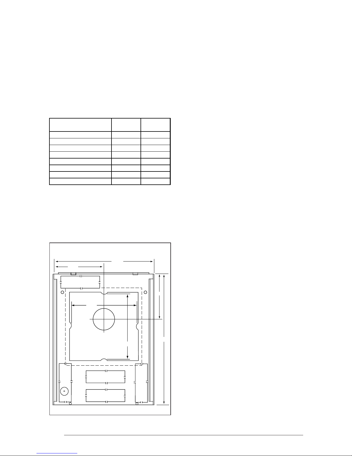
9-1/8
Feeder Duct
12-1/8
Flue
Location
Opening
7-1/8 X 2-3/16 Knock-outs
Combustion Air
FRONT
18-1/4
12-1/8
8-3/8
24-1/8
(b) Inspect the venting system for proper size
and horizontal pitch, as required in the
ANSI Z223.1/NFPA 54, (National Fuel Gas
Code) and ANSI/NFPA 31 (Installation of
Oil
Burning Equipment), and these instructions. Determine
that there is no blockage or restriction,
leakage, corrosion
or other deficiencies which could cause an
unsafe condition.
(c) In so far as is practical, close all building
doors and windows and all doors between
the space in which the appliance(s) connected to the venting system are located
and other spaces of the building. Turn on
clothes dryers and any appliance not connected to the venting system. Turn on any
exhaust fans, such as range hoods and
bathroom exhausts, so they shall operate
at maximum speed. Do not operate a
summer exhaust fan. Close fireplace
dampers.
Figure 2. MA-200 Base Pan
6
(d) Follow the lighting instructions. Place the
appliance being inspected in operation.
Adjust thermostat so appliance shall operate continuously.
(e) Test for draft hood equipped appliance
spillage at the draft hood relief opening
after 5 minutes of main burner operation.
Use the flame of a match or candle.
(f) After it has been determined that each
appliance connected to the venting system properly vents when tested as outlined above, return doors, windows,
exhaust fans, fireplace dampers and any
other gas burning appliance to their previous conditions of use.
Slit 4 Corners
Base
Bend Over Tabs
Flange
Slit 4 Corners
Flange
Bend Over Tabs
Bend Down 4 Sides
Heater Duct Below Joists
Bend Down 4 Sides
Base
Heater Duct Below Joists
Floor
Joists
TRANSITION
DUCT
Floor
Joists
(g) If improper venting is observed during any
of the above tests, the venting system
must be corrected.
Unit Location and Clearance to Adjacent
Material Requirements
The unit must be installed in a level position. The
furnace must be installed with the minimum
clearances from adjacent materials as stated in
Table 2. Additional clearance should be provided
to permit servicing of filters, blower, motors,
controls, combustion air connections, and vent
connections.
UNIT INSTALLATION
These instructions are intended for the use of
qualified individuals specially trained and
experienced in installation of this type equipment
and related system components. Installation
and service personnel are required by some
governing bodies to be licensed. Persons not
qualified should not attempt to install this
equipment or interpret these instructions.
MA-200 Base Installation
The MA-200 base is designed for O.E.M. and
replacement installation of the CMF2 series
furnace (see Figures 2 and 3). The warm air
duct system should be designed so the duct
static pressure external to the furnace does not
exceed the static pressure listed on the furnace
data label.
Figure 3. Transition and Offset Ducts
Feeder Duct
12-1/8
7-1/8 X 2-3/16 Knock-outs
Opening
24-1/2
12-1/8
Combustion Air
18-1/4
Use the base pan to mark the 12-1/8" x 12-1/
8" center opening for the feeder duct. When the
4" offset feeder duct is used, the floor opening
will be offset 4 inches from the opening in the
main duct. If using the combustion air duct,
select and knock out the combustion air opening to be used. Then mark the 2-1/4" x 7-1/4"
opening for the combustion air duct.
Cut This Line
Bend Over
1"
Base
Heat Duct Below Joists
Feeder Duct
Along This Line
Floor
Joists
Figure 4. MA-100 Universal Base,
Bottom Panel
Figure 5. Feeder Duct Installation
7

Cut the opening for the feeder duct 14-1/8" x 141/8" in flooring (cutting opening 1" larger all the
way will allow the flanges on the underside of the
base pan to fit in the opening).
the feeder duct. If using the combustion air duct,
select and knock out the combustion air opening to be used. Then mark the 2-1/4" x 7-1/4"
opening for the combustion air duct.
If using the combustion air duct, cut the opening
for the duct about 1/8" larger than the marking
on the floor. Be sure to cut through all insulation
and the bottom board so that the combustion air
duct is unobstructed to outside air.
Drill an approximate 1" diameter hole for the fuel
line through the floor and bottom board to the
outside. Fuel lines are not supplied with the
furnace. They should be installed to comply with
all applicable codes.
Drop transition or offset feeder duct upside
down through the floor opening and center the
top of the feeder duct in 14-1/8" x 14-1/8" floor
opening. Using the feeder duct as a guide, mark
and cut a 12" x 12" opening in the distribution
duct. (See Figure 3)
Insert the feeder tabs into the main duct and
bend them over tightly so that the main duct
edges are trapped between flanges and tabs.
Metal tape may also be used to ensure an air
tight connection.
Install the base pan around the feeder duct with
the (2) screws through the holes towards the
rear of the base pan.
Slit the corners of the feeder duct down to the
top of the base pan. While the top of the distribution duct is pulled up with one hand, bend
down each side of the feeder duct tightly to the
base with the other hand. Trim the metal to allow
a one inch flange over the top of the base pan
and seal that flange with the metal tape.
If a “V” or “U”-box crossover system is to be
used, see the instructions provided with the
crossover system.
MA-100 Universal Base Installation
The MA-100 base is designed primarily for
replacement installation of the CMF2 series
furnace where the manufactured home duct
system may be small and restrictive to proper
air flow. The MA-100 base provides approximately four (4) inches of additional plenum
space before the discharge air enters the manufactured home duct system. (See Figures 4 and
5)
Use the bottom panel of the base assembly to
mark the 12-1/8" x 12-1/8" center opening for
8
Cut the opening for the feeder duct 14-1/8" x 141/8" in flooring (cutting opening 1" larger all the
way around 12-1/8" x 12-1/8" template marking). This will allow the four flanges on the
underside of the panel to fit into the opening.
If using the combustion air duct, cut the opening
for the duct about 1/8" larger than the marking
on the floor. Be sure to cut through all insulation
and the bottom board so that the combustion air
duct is unobstructed to the outside air.
Drill a 1" hole for the fuel line through the floor and
bottom board to the outside. Fuel lines are not
supplied with the furnace. They should be
installed to comply with local codes.
Put the bottom base panel in place (See Figure
5). Drop the transition feeder duct upside down
through the opening and mark a 12" x 12"
opening to be cut into the distribution duct.
Remove the bottom panel and transition feeder
duct; then cut the opening into the distribution
duct.
Install the feeder duct by bending the tabs inside
the heat duct and using the metal tape to insure
an airtight connection.
Set the bottom base panel over the feeder duct.
Slit the corners of the feeder duct down to the
top of the base. While the top of the distribution
duct is pulled up with one hand, bend down each
side of the feeder duct tightly to the base with the
other hand. Trim the metal to allow one inch
flange over the top of the base and seal that
flange with the metal tape.
Secure the top panel to the floor with two (2)
screws through the front flange.
If a “V” or “U”-box crossover system is to be
used, see the instructions provided with the
crossover system.
Combustion Air Duct/Pipe Installation
The CMF2 furnace must draw the combustion
air from outside, except for special installations
(See Table 1). This can be accomplished either
by using the 2”X7” rectangular combustion air
duct provided in the MA series base kits or using
the direct vent kit.
When the rectangular combustion air duct is to
be used, install the combustion air duct through
the selected knockout in the base. For direct
vent applications, the rear knock-out in the
furnace base cannot be used. After the
combustion air duct has been positioned, install
the combustion air adapter. This adapter will
transition the 2”X7” opening of the combustion
air duct to the 2” diameter of the burner flexible
tubing. This adapter is included in the MA series
base kits. For retrofit applications in which the
MA series base is already installed, the
combustion air adapter can be ordered as a kit.
Refer to the Replacement Parts List for more
details on ordering this kit.
Secure the adapter with either wood or metal
fasteners (field provided), depending upon the
particular installation. Ensure that the gasket for
the adapter is positioned properly before
installing the adapter. Attach the flexible hose
from the burner to the combustion air adapter
using the provided metal hose clamp.
When the direct vent kit is used, follow the
instructions provided with the kit. Note: The
direct vent kit should be installed before
positioning the furnace on the base.
Damper Installation
An automatic shut-off damper is available (see
replacement parts list). An automated shut off
damper is required when the home is air conditioned by a self-contained unit. This damper
is designed to fit in the feeder duct cavity,
directly under the furnace. A damper is required
to prevent chilled air from flowing over the
furnace heat exchanger. For proper installation, refer to the instructions provided with the
damper.
Open the access door. Fasten the front of the
furnace and the base to the floor with #8 x 1/2"
long sheet metal screws.
Using the provided hose clamp, secure the
flexible combustion air tubing from the burner to
the combustion air adapter.
Installation of Furnace onto the MA-100
Base
Tilt the furnace forward and carefully work the
furnace back over the MA-100 Universal base.
Lift the furnace as necessary when positioning
the unit over the base assembly to prevent any
damage to the feeder duct assembly and combustion air adapter, if present.
Be sure the furnace is positioned all the way to
the back of the base assembly.
Open the furnace door and fasten the furnace
to the base using #8 x 1/2" long sheet metal
screws.
Using the provided hose clamp, secure the
flexible combustion air tubing from the burner to
the combustion air adapter.
CB-200A Cottage Base Installation
The CMF2 can be installed on a CB-200A
cottage base in certain applications, as
described earlier in these instructions (See
Table 1). Refer to the Replacement Parts List
Installation of Furnace onto the MA-200
Base
Lift the furnace over the base so that the flange
at the back comes to rest on the inside rails of
the base.
Raise the front of the furnace to clear the gasket
on the bottom of the furnace and slide the back
until the rear flange drops into the channel at the
rear of the base. Be careful not to damage the
combustion air adapter, if present, while positioning the unit.
Be sure that the furnace is all the way back so
as to engage the tabs on the rear flange on the
base.
Figure 6. Closet Installation
9
 Loading...