

Page 1
Installation Instructions
B3BV Series Electric Furnaces
For HUD approved installations in manufactured homes and modular homes
These instructions are intended to assist qualified individuals experienced in the proper
installation of heating and/or air conditioning appliances. Some local codes require
licensed installation/service personnel for this type equipment. All installations must be
in accordance with these instructions and with all applicable national and local codes
and standards. Improper installation, service, adjustment, or maintenance can cause,
fire, electrical shock or other conditions which may result in personal injury or property
damage. Unless otherwise noted in the instructions, only factory authorized kits or
accessories may be used when modifying this product.
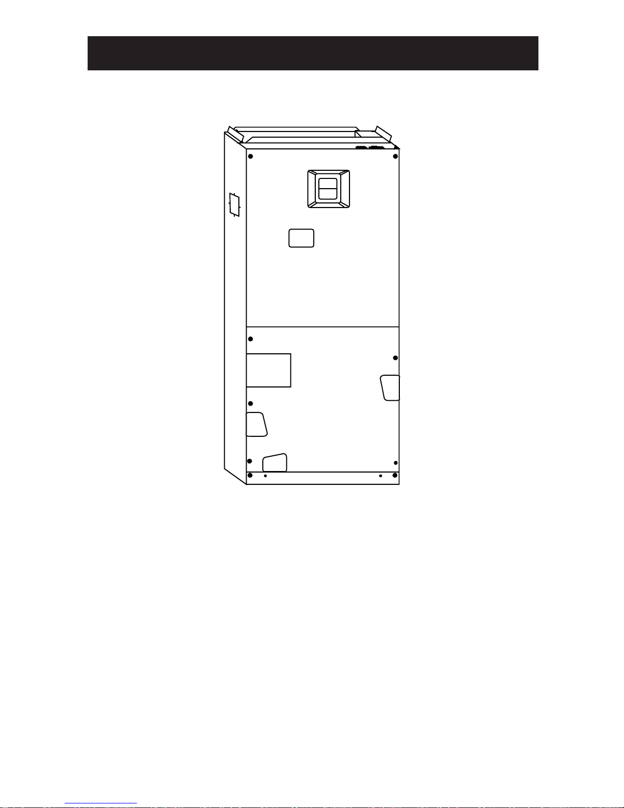
INTRODUCTION
The B3BV Series electric furnaces are approved for use in HUD code manufactured
homes (HUD Manufactured Home Construction and Safety Standard (Title 24, Part
3280)) and other modular home applications.
The B3BV Series electric furnace may be installed in downflow or upflow applications
as “freestanding” units, and in closet or alcove installations.
B3BV Series electric furnaces are supplied with factory installed electric heat. Approved
NORDYNE heat-pump/air conditioning coils may be installed in the field.
Page 2

GENERAL INFORMATION
Codes
All electrical power wiring for the B3 series
electric furnace must be installed in accordance with:
1) HUD Manufactured Home Construction and Safety Standard
2) NFPA 70 - National Electric Code
(NEC)
rules. Do not leave disconnected after
servicing or adding A/C to the system.
RETURN AIR
In closet or alcove installations provide at
least 235 square inches free opening for
return air for B-cabinet (19 3/4" wide)
models and 300 square inches for Ccabinet (22 1/2" wide) models.
NOTE : Circuit breakers installed in the
B3 electric furnace are for short-circuit
protection of the internal wiring and to
serve as a unit disconnect. Circuit break-
ers installed in the B3BV electric furnace
DO NOT provide over-current protection
of the supply wiring. Over-current protection of the supply wiring must be provided
at the distribution panel and sized as shown
in the installation instructions or on the unit
data label, and per the NEC.
Location
Reference the installation instruction included with this unit for location requirements.
Clearance
All electric heater kits less than 20 kw are
approved for use in air handler installations with zero-clearance to combustibles
at any blower speed. For horizontal and
upflow configuration, air handlers
equipped with 20 kw electric heater kits
are approved for installation with zero
clearance to combustibles at any blower
speed. When using a 20 kw electric heat
kit in a downflow installation, the blower
must be set for high speed for both heating
and cooling.
VENTILATION
The B3BV electric furnace has a cut-out on
each side for ventilation air. Use
NORDYNE part number 914120 or
914427 adaptor with Ventilaire III or IV to
supply the proper amount of ventilation
air. The VentilAire connections must be
made for the system to conform to H.U.D.
The return air opening can be located in a
closet door or a sidewall. If the return air
opening is directly adjacent to the side (or
front) of the air handler, 6" minimum clearance must be provided between the side
of the furnace and the return air opening.
If no part of the return air opening is directly
adjacent to the unit no clearance is required.
If an upflow pedestal mounting stand is
fabricated in the field it must be constructed
strong enough to support the unit with all
accessories installed (approximately 130
lbs. for B-cabinet models and 200 lbs. for
C-cabinet models). The construction of
the pedestal stand must also allow for at
least 235 square inches free opening (300
square inches for C-cabinet models) in the
application. Field fabricated upflow pedestal mounting stands must be constructed
of noncombustible materials.
Refer to the installation instruction included
with this unit for other return air details.
SUPPLY AIR DUCTS
The duct system must be designed so that
the external static pressure of the system
does not exceed the maximum external
static pressure indicated on the unit data
label.
Downflow applications require the use of
a plenum connector shown in Figure 1 or
its equivalent if the supply air ducts pass
through the floor of the structure. See
Table 1 for plenum connectors available.
2
Page 3
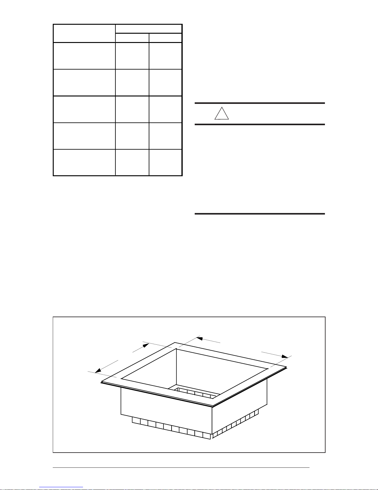
Description
Downflow Plenum
Connect o r, 6. 25 "
Downflow Plenum
Connect o r, 8. 25 "
Downflow Plenum
Connector, 10. 25"
Cabinet Size
BC
913840 914969
913841 914970
913842 914971
INSTALLATION
Install the unit as directed in the Installation Instructions. NOTE: Secure the unit to
the structure using metal strap and/or fasteners at the top of the unit and at the
bottom of the unit.
POWER WIRING
!
W ARNING:
Upflow Pedes t al
Mo un ting Stan d
Downflow Coil
Adaptor
Table 1. Optional Accessory Kits
The plenum connectors are designed for
use with trunk ducts having a minimum
width of 12 in. If sufficient space is not
available to adequately bend and secure
plenum tabs it may be necessary to attach
the connector to the duct using sheetmetal fasteners and seal with an approved
foil tape.
Plenum connectors may be field constructed but must meet requirements as
stated in the unit installation instructions.
913872 913873
917343A 917344A
To avoid risk of electric
shock, personal injury, or
death, disconnect electrical
power to the unit before
performing any maintenance
or service. The unit may have
more than one electric power
supply.
All wiring must comply with the current
revision of the National Electric Code and
must be sized for the minimum ampacities
as listed on the unit data label or in Table
2.
If a single circuit adaptor kit is used, it may
need to be re-configured for some appli-
13.25"
18.5" (B-Cab.)
21.25" (C-Cab.)
Figure 1. Plenum Adapter
3
Page 4

Model # Vol tage KW
15 K W 240 14. 4
20 K W 240 19. 2
B3BV
Minimum Circuit Maximum Over-Current
Ampacity Protection
Circuit Circuit Single Circuit Circuit Single
ABCircuitABCircuit
55.0 25.0 80.0 60.0
55.0 50.0 105.0 60.0
Table 2. Electrical Data
30.0 90.0
50.0 125.0
cations. Remove the single circuit adaptor
kit cover and verify that the lugs are configured correctly for the application. If the
lugs are not configured for the application,
refer to the instructions included with the
kit and modify the configuration. Install the
single circuit adaptor kit (if used) in the line
side (“on” end) of the circuit breakers.
Tighten the lugs securely (45 in-lbs recommended).
Connect the supply wiring to the circuit
breakers, single circuit adaptor kit, or terminal block. Tighten the lugs securely.
When using dual supply circuits verify that
the supply sized for circuit “A” is connected
to the circuit breaker that is connected to
the top element assembly.
Replace metal circuit breaker line cover.
Refer to Figure 2 for thermostat wiring
examples.
A/C or H/P COIL INSTALLATION
Approved air conditioning and heat pump
system components are listed on the unit
nameplate.
To install the indoor coil:
1. Remove door cover plate, door and
coil close-off plate (with insulation).
Discard door cover plate.
2. For upflow applications slide the coil
into the track located in the bottom of
the unit.
3. For downflow applications the downflow adaptor (see Table 1) must be
used. Install the downflow adaptor
and coil as directed in the instructions
included with the kit.
4. Reinstall the door and coil close-off
plate (with insulation). NOTE: In
downflow applications the door is rotated 180° so that the refrigerant and
condensate lines remain on the left
side.
5. Install the refrigerant and condensate
lines as directed in the instructions
included with the outdoor unit.
MOTOR SPEED SELECTION
The blower speed is preset at the factory
for operation at the same speed for heating and cooling. For optimum system performance and comfort, it may be necessary to change the factory set speed. To
change the blower speed, disconnect all
electrical power to the unit and remove the
upper door. Connect the black wire from
the motor to the desired blower speed
marked on the terminal block of the blower
motor. Terminal 4 = High Speed, Terminal
5 = Med Speed and Terminal 6 - Low
Speed.
Replace the upper door and secure it to
the unit. Restore power to the unit.
High speed operation is required when
using a 20 kw electric heater kit in a
downflow application.
4
Page 5
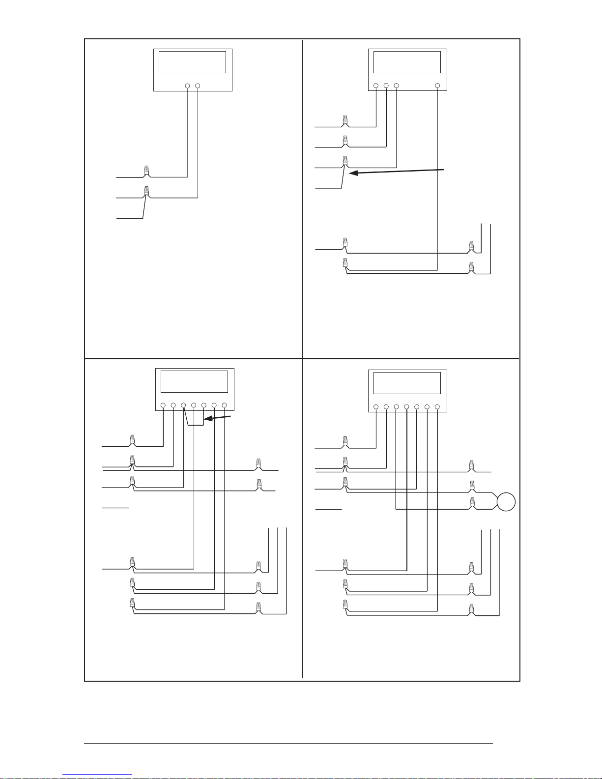
Thermostat
W
R
Thermostat
GRW
Y
Red
Brown
Orange
B3BV Electric
Furnace
Typical Heating Only System
Connection
Thermostat
GRW2CEOY
Green
Red
Brown
Orange
Grey
B3BV Electric
G
R
W
1
W
2
C
A/C OD Section
Furnace
Typical Air Conditioning System
Connection
Thermostat
GRW2CEOY
NOTE: Connect "W"
leads together when
staged heater kits are
used without outdoor
thermostats
YC
NOTE: Jumper
between W2 and E is
required when no OD
T-Stat is
Green
Red
Brown
Orange
Grey
B3BV Electric
G
R
W
1
W
2
C
Heat Pump OD
Furnace
Typical Heat Pump System Connection
used.
C
Section
R
W
OY
Green
Red
2
Brown
Orange
Grey
B3BV Electric
Typical Heat Pump System Connection
G
R
W
1
W
2
C
Furnace
with Optional Outdoor Thermostat
Figure 2. Typical Air Conditioning and Heat Pump System Connections
R
W
2
OD
E
Stat
OY
C
Heat Pump OD
Section
5
Page 6

PLUG
MOTOR
BLOWER
1
4
6
5
1 = COM
2 = CAP
3 = CAP
4 = HIGH
5 = MED
6 = LOW
3
2
RED
RED
RED
RED
ELEMENTS
as shown. See the Installation Instructions.
NOTES:
1. The blower motor speed tap connection may not be
Match the tap position with the supply voltage used.
copper wire of the same gauge.
BLACK
2. Disconnect all power before servicing.
3. Transformer may have a dual voltage primary tap.
4. If the internal wiring is replaced, use only 105°C
5. Aluminum or copper supply conductors are suitable.
BLACK
CONTACTOR
BLACK
CONTACTOR
ELEMENTS
BLACK
LIMIT
LIMIT
GRAY
GRAY
BLACK
BLACK
BLACK
BLACK
WHITE
CIRCUIT
BREAKERS
GROUND
SUPPLY VOLTAGE
*Note: Fuse may not be
present on some models.
BLUE
BROWN
YELLOW
24V
123
WHITE
BLACK
RED
BLOWER RELAY
BROWN
VOLTAGE
1
W
GRAY
N.O
2
5
N.C
1
2
W
TRANSFORMER
Com
46
3
LOW
RED
BLACK
*
FUSE
RED
GRAY
GREEN
Air Handler with Factory Installed Heat (20 kw)
RCG
4
ORANGE
GRAY
ORANGE
56789
BLACK
2
1
GRAY
1 = COM
BROWN
3
2 = CAP
3 = CAP
4 = HIGH
654
5 = MED
6 = LOW
HEATER KIT PLUG
3 SPD. MOTOR
Figure 3. Typical System Wiring Diagram (20 kw, 2 Stage Shown)
FACTORY WIRING
LOW VOLTAGE
FIELD WIRING
HIGH VOLTAGE
710283
6
Page 7
2
3
1
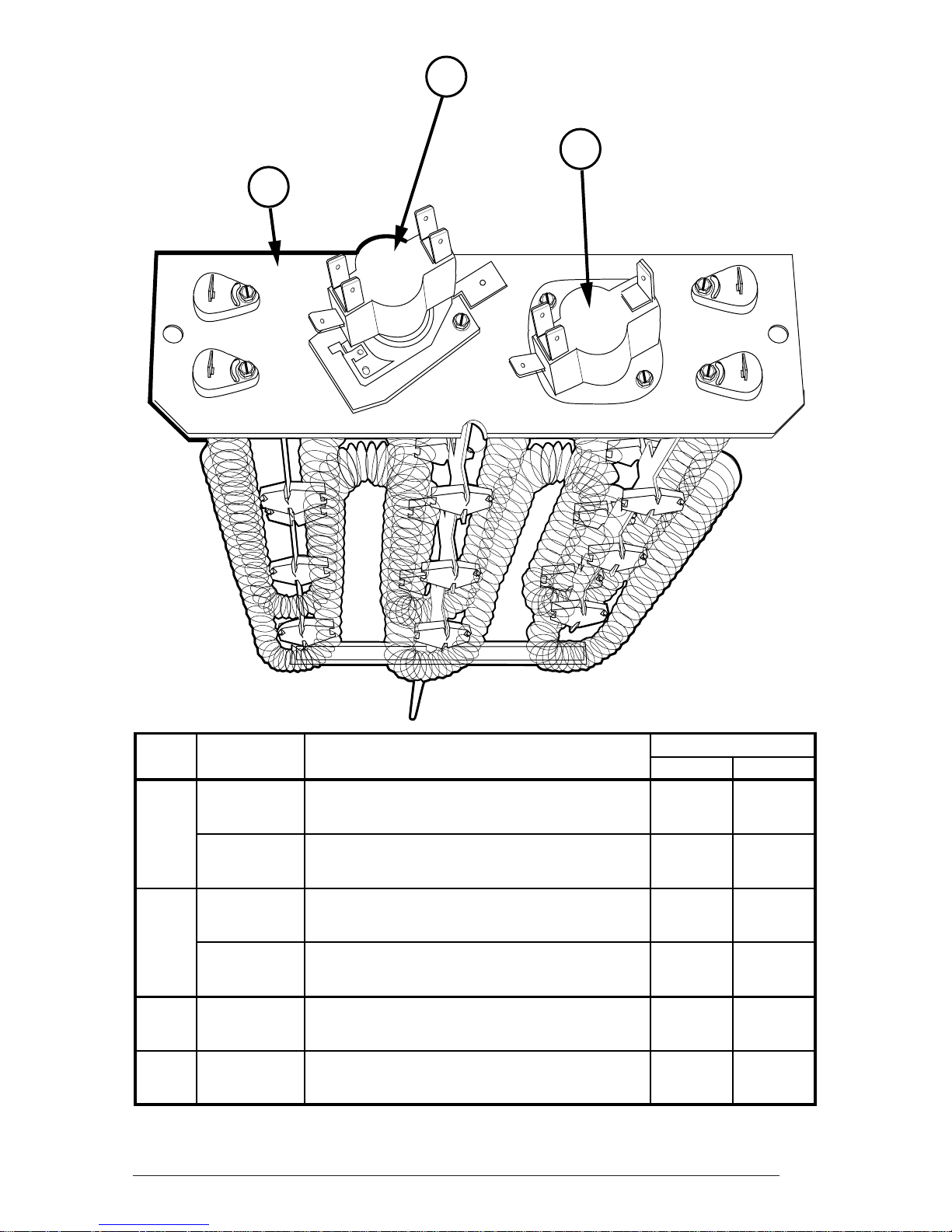
ITEM PART B3BV
NO. NO. DESCRIPTION 015K-B 020K-B
1 270012 Element A ss em bly - 4. 8 k w 1
270006 Element A ss em bly - 9.6 k w 1 2
2 621908 Contact or, 1-pole 1
621909 Contact or, 2-pole 1 2
3 626518 Limit, 1-pole, 160° F 2 2
4 632249 Circuit Br eaker, 2-pole, 60 amp (not shown) 2 2
Heater Kit Replacement Parts List
7
Page 8

INSTALLER: PLEASE LEAVE
THESE INSTALLATION INSTRUCTIONS
WITH THE HOMEOWNER
¢708195C¤
708195
O’Fallon, MO
7081950 (Replaces 7081020)
Specifications and illustrations subject to change
without notice and without incurring obligations.
Printed in U.S.A. (10/02)
 Loading...