

Nordyne 460/575 Volt Single Package Convertible Air Conditioner, Air Conditioner User Manual And Installation Instructions
Page 1

460/575 Volt Single Package Convertible Air Conditioner
User's Manual and Installation Instructions
TM
These instructions are primarily intended to assist qualified individuals
experienced in the proper installation of heating and/or air conditioning
appliances. Some local codes require licensed installation/service personnel for this type equipment. All installations must be in accordance
with these instructions and with all applicable national and local codes
and standards.
Read these instructions thoroughly before starting the installation. Follow
all precautions and warnings contained within these instructions and on
the unit.
Page 2
OWNER INFORMATION
make sure it’s working right, clean or change
filters and make any needed adjustments.
OPERATING INSTRUCTIONS
To Turn On Air Conditioner
If you have a heating/cooling thermostat:
1. Set the system switch to “Cool”.
2. Set the thermostat at the temperature level
you desire.
3. Turn the power on. Your air conditioner
should start as soon as room temperature
rises above the setting on the thermostat.
If you have one thermostat for heating and
another for cooling, they must be inter-
locked to prevent simultaneous operation:
1. Turn the heating thermostat to its lowest
possible setting.
2. If the cooling thermostat has an “On/Off”
switch, turn it “On.”
3. Set the cooling thermostat to the desired
temperature.
4. Turn the power on. Your air conditioner
should start when room temperature exceeds the thermostat setting.
To Shut Off Air Conditioner
If you have a heating/cooling thermostat:
1. Turn the system switch to “Heat” or “Off”.
2. Turn the thermostat to the desired heating
temperature setting.
3. If you are turning your air conditioner off for
the winter or an extended period, shut off the
power to the air conditioner.
If you have one thermostat for heating and
another for cooling, they must be interlocked to prevent simultaneous operation:
1. Turn your cooling thermostat “Off” or to its
highest setting.
2. Turn the heating thermostat to the desired
temperature.
3. If you are turning your air conditioner off for
the winter or an extended period, shut off the
power to the air conditioner.
Otherwise, follow these simple rules:
1. Never run your system without filter. If you
do, the cooling coils will get dirty and may
become clogged.
2. Set your thermostat at the comfort level you
wish – and then leave it alone. Let it control
the operation of the air conditioning system.
If you get chilly, turn it up a degree at a time
until comfort is restored.
3. It takes longer for an air conditioner to cool
your dwelling than it does for your furnace to
heat it. So. . . don’t turn the unit on and expect
a dramatic drop in temperature, at least not
right away. If your home is hot and humid, the
temperature will drop slowly.
4. Check your filters every ten days in summer
to see if they are dirty. To keep them clean,
use a mild solution of detergent and water on
washable types. Replace non washable filters.
5. Keep your condenser coil clean. You can
hose it down when it gets dirty.
If your air conditioner isn’t working:
1. Make sure the fuses are not blown or that
your circuit breakers are on.
2. See that your thermostat is set at the desired
temperature and that your system’s switch is
on “Cool”.
3. For free air flow, make sure your return
register is not covered and that the filter is
clean.
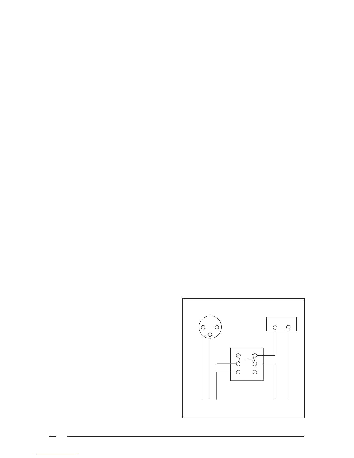
Cooling
Thermostat
R
Double Throw
Double Pole Switch
Furance
Thermostat
R
BEFORE YOU CALL A SERVICEMAN
Let your serviceman check your system at the
start of each air conditioning season. He will
2
To Air Conditioner
To Furance
Figure 1. Thermostat Interlock System
Page 3
4. Check the condenser coil and make sure it
is clean and not clogged with grass or leaves.
If your air conditioner still isn’t working, call your
nearest distributor.
SPECIFICATIONS
personal injury or property damage.
Unless otherwise noted in these instructions, only factory authorized kits or
accessories may be used with this product. Noncompliance may void the unit’s
warranty.
Package Air Conditioners are designed for
outdoor rooftop or ground level slab installations.
The units are shipped ready for horizontal duct
connections and are easily converted for down
flow applications.
All models are shipped from the factory with the
following:
1. Zero clearance to combustibles
2. Multi-speed direct-drive blower.
3. Compressor Anti-short-cycle timer (single
phase models only).
4. Blower Speed Relay.
5. Horizontal or Down flow duct connections.
The unit dimensions are shown in Figure 2 .
Optional field-installed electric heater kits are
available in 5 kw through 20 kw heating
capacities. A separate installation instruction
document for the electric heaters and their
application accompanies this one. A single
stage cooling 24VAC thermostat should be used
with these units. If electric heat will be installed,
a single-stage cooling, single stage heating
thermostat will be required.
SAFETY CONSIDERATIONS
It is the responsibility of the installer to ensure
that the installation is made in accordance with
all applicable local and national codes.
Labels, Tags — When working with this
equipment, follow all precautions in the literature,
on tags, and on labels provided with the unit and/
or approved field installed kits. The type of
hazard and severity are described on each label
or tag.
!
WARNING:
Improper installation, service, adjustment, or maintenance may cause explosion, fire, electrical shock or other hazardous conditions which may result in
Pressures Within The System — This
equipment contains liquid and gaseous
refrigerant under high pressure. Installation or
servicing should only be performed by qualified
trained personnel thoroughly familiar with this
type equipment.
INSTALLATION REQUIREMENTS
Equipment Check — Before beginning the
installation, verify that the unit model is correct
for the job. The unit model number is printed on
the data label. All units have been securely
packaged at the point of shipment. After
unpacking the unit, carefully inspect it for
apparent and concealed damage. Claims for
damage should be filed with the carrier by the
consignee.
Requirements and Codes — The installer
must comply with all local codes and regulations
which govern this type equipment. Local codes
and regulations take precedence over any
recommendations contained in these
instructions. All electrical wiring must be made
in accordance with local codes and regulations
and with the National Electric Code (ANSI/NFPA
70) or in Canada the Canadian Electric Code
Part 1 CSA C.22.1. Air Ducts must be installed
in accordance with the standards of the National
Fire Protection Association “Standards for
Installation of Air Conditioning and Ventilation
Systems” (NFPA 90A), “Standard for Installation
of Residence Type Warm Air Heating and Air
Conditioning Systems” (NFPA 90B), these
instructions and all applicable local codes.
NFPA publications are available by writing:
National Fire Protection Association
Batterymarch Park
Quincy, Maine 02269
Unit Location — This air conditioner is designed
only for outdoor installations. Choosing the
location of the unit should be based on minimizing
the length of the supply and return ducts.
Consideration should also be given to availability
3
Page 4
of electric power, service access, noise, and
shade. Sufficient clearance for unobstructed
airflow through the outdoor coil must be
maintained in order to achieve rated performance
See Figure 3 for minimum clearances to
obstructions.
Air Filter Requirements — Three phase
units “Only” are supplied from the factory with
an internal filter rack assembly. Air filters are
not supplied; a suitable air filter must be installed
in the unit or in the return air system for all units.
See Table 1 for internal filter size requirements.
When utilizing an Economizer or Fresh Air
Equipment, the factory installed filter rack
assembly must be removed prior to installation.
Air filter pressure drop must not exceed 0.08
inches WC. Air filter(s) must be installed in the
return air ductwork ahead of the evaporator
coil of this unit. All return air to this unit must
pass through the filter(s) before entering this
unit. (See Routine Maintenance for Installation/
Removal of air filters).
INTERNAL FILTER
UNIT SIZE SIZE
R4GA 024-042, R4BC 024 (2) 14” x 25” x 1”
P4SA 036, P4SA 048 or
P4SC 036, Q4SA 036 (2) 14” x 25” x 2”
R4GA 048-060, R4GC 030-042 (2) 16” x 25” x 1”
P4SA 060, P4SC 048-060, or
Q4SA 048-060, Q4SC-048-060 (2) 16” x 25” x 2”
R4GC 048-060 (2) 18” x 25” x 1”
R4GM 024-072 or
Q4SC 048-060 (2) 18” x 25” x 2”
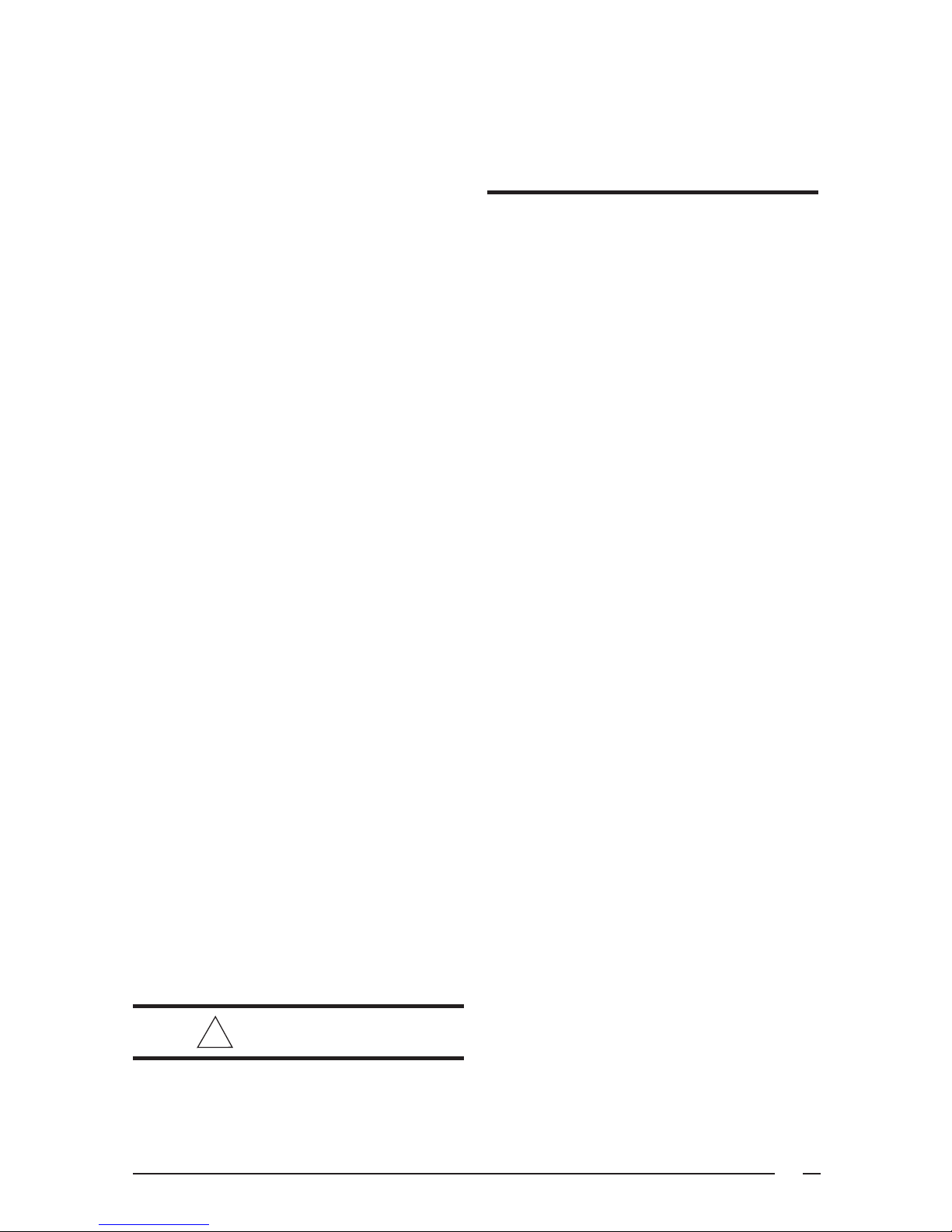
Securing
Screw
Figure 3a. Internal Filter Rack Location
located on the front side of the unit. (See Figure
4.) Install a 2 inch condensate trap in the drain
line of the same size and prime with water. When
connecting rigid drain line, hold the female fitting
with a wrench to prevent twisting. Do not over
tighten! Refer to local codes and restrictions
for proper condensate disposal requirements.
UNIT INSTALLATION
Ground Level — When installing the unit at
ground level, provide a concrete mounting
pad separate from the building foundation.
The pad must be level to insure proper
condensate disposal and strong enough to
support the unit’s weight. Refer to Figure 2 .
Make sure the slab is a minimum of 2" above
the grade and in an area that drains well.
Table 1. Internal Filter Size Requirements.
Removal of Internal Filter Rack — First
remove the Return Air Panel from the unit.
Remove the height adjustment screw from the
inside of the rack, and the (1) screw securing
the assembly to the coil located on the left leg
of the rack. The assembly can easily be
collapsed and removed from the unit. See
Figure 3a for filter rack securing screw
locations.
For single phase downflow installations only,
an internal filter accessory kit can be ordered.
For horizontal installations, the air filter system
must be installed in the return air ductwork. All
return air to this unit must pass through the
filter(s) before entering the evaporator coil.
Condensate Drain — Condensate is removed
from the unit through the 3/4" female pipe fitting
4
!
WARNING:
To avoid the risk of property damage or
personal injury; it is the rigger’s
responsibility to insure that whatever
means are used to hoist the unit are
safe and adequate.
!
CAUTION:
All panels must be securely in place
when rigging and hoisting.
Rigging and Hoisting — The unit should be
lifted using slings and spreader bars. The
spreader bars are necessary to prevent
damaging the top of the unit’s cabinet. Make
sure that the lifting equipment is adequate for
Page 5

DOWNFLOW
SUPPLY DUCT
OPENING
24.9
3/4" NPT Female
Drain Connector
30.0
27.2
23.6
B
1.8
1.75 Ø Power Entry (Capped)
1.25 Ø Power Entry
0.88 Ø Control Wiring Entry
13.3
12.0
13.5
A
16.0
CG
13.5
23.5
Top View
C
14.7
47.5
16.0
12.0
DOWNFLOW
RETURN DUCT
OPENING
FILTER
ACCESS PANEL
5.0
SUPPLY
13.5
8.0
16.0
13.45
3 PHASE ONLY
HORIZONTAL
RETURN DUCT
16.0
OPENING
13.5
4.0
CONDENSING
COIL
Side View Back View
Model No. C
3 Ton
4 Ton
5 Ton
Unit
Weight
330 27.5 26.5 35.0 31.3
345 28.0 26.0 35.0 31.3
380 28.5 26.5 39.0 35.3
4.00
11.75 22.75
55.8
Center of Gravity Height (in inches)
A
B
with base rails without base rails
Figure 2. Dimensions
5
Page 6

36"
72"
36"
36"
6"
Figure 3. Minimum Clearances
the load. Refer to Figure 2 for unit weights.
Keep the unit in an upright position at all times.
For rooftop installations, remove and
discard the two supports attached beneath
the unit.
The rigging must be located outside the unit’s
center of gravity. Refer to Figure 2 for center
of gravity location.
Rooftop — For rooftop installations use the
appropriate accessory roof curb and follow all
instructions included with it. Make sure the two
supports beneath the unit have been removed.
Locate the unit according to local building codes
and ordinances. The curb must be level to insure
proper condensate drainage. (See Figure 6)
The roof must be capable of handling the weight
of the unit. (See Figure 2) for unit weights.
Reinforce the roof if required.
AIR DUCTS
Installation of Air Conditioning Systems” (NFPA
90A), “Standard for Installation of Residence
Type Warm Air Heating and Air Conditioning
Systems” (NFPA 90B), and all applicable local
codes.
Design the duct work according to methods
described by the National Warm Air Heating and
Air Conditioning Association (ACCA). The ducts
▼▼
▼
▼▼
This unit is designed only for use with a supply
and return duct. Air ducts should be installed in
accordance with the standards of the National
Fire Protection Association “Standard for
6
Condensate Drain
Figure 4. Condensate Drain
Page 7

2"
Figure 5. Ground Level Installation
must be properly sized not to exceed .2" w.c.
pressure drop at 400 scfm per nominal ton of
cooling capacity.
Duct work should be attached directly to the unit
flanges for horizontal applications. On roof curb
installations the ducts must be attached to the
curb hangers, not the unit.
Unconditioned Spaces — All duct work
passing through unconditioned space must be
properly insulated to minimize duct losses and
prevent condensation. Use insulation with an
outer vapor barrier. Refer to local codes for
insulation material requirements.
Acoustical Duct Work — Certain installations
may require the use of acoustical lining inside
the supply duct work. Acoustical insulation must
be in accordance with the current revision of the
Sheet Metal and Air Conditioning Contractors
National Association (SMACNA) application
standard for duct liners. Duct lining must be UL
classified batts or blankets with a fire hazard
classification of FHC-25/50 or less. Fiber duct
work may be used in place of internal duct liners
if the fiber duct work is in accordance with the
current revision of the SMACNA construction
standard on fibrous glass ducts. Fibrous duct
work and internal acoustical lining must be
NFPA Class 1 air ducts when tested per UL
Standard 181 for Class 1 ducts.
Horizontal to Down flow Conversion — The
unit is shipped ready for horizontal duct
connections. If down flow ducts are required,
the unit must be converted following the steps
below for both the supply and return ducts.
Figure 6. Roof Top Installation
1) Locate the duct cap inside the duct
openings and remove the screw holding
it in place.
2) Lift the cap out of the unit. (The cap can
be pushed up from the bottom by
reaching through the fork slot).
3) Cover the horizontal duct opening with
the cap. The insulation will be on the
indoor side.
4) Fasten the cover with screws and seal
to prevent air leakage.
Clearance — This unit is approved for 6 inch
clearance.
ELECTRICAL WIRING
General — Electrical power wiring must be
made in accordance with all applicable local
codes and ordinances, and with the current
revision of the National Electric Code NFPA 70
or in Canada CSA C.22.1 - Canadian Electrical
Code Part 1. If any of the original wire as supplied
with the unit must be replaced, it must be
replaced with material of the same gage and
temperature rating.
!
WARNING:
To avoid the risk of electrical shock,
personal injury, or death, disconnect all
electrical power to the unit before
performing any maintenance or service.
The unit may have more than one
electrical power supply.
7
Page 8

Line Voltage — Before proceeding with the
3 T
ISOLATE
Violet
ISOLATE
4
ISOLATE
Violet
ISOLATE
electrical connections, make certain that the
voltage, frequency, and phase of the supply
source are the same as those specified on the
unit rating plate. Also verify that the service
provided by the utility is sufficient to handle the
additional load imposed by this equipment.
See the unit wiring label for proper high and low
voltage wiring. Make all electrical connections
in accordance with all applicable codes and
ordinances.
Use a separate branch electrical circuit for this
unit. A means of electrical disconnect must be
located within sight of and readily accessibility to
the unit. Internally mounted circuit breakers are
available as field installed options. These circuit
breakers can be used as an electrical
disconnect. For maximum ampacity and over
current protection, see the unit rating plate.
Provide power supply (or supplies) for the
unit in accordance with the unit wiring diagram,
and the unit rating plate. Connect the linevoltage leads to the corresponding terminals
on the contactor (or the circuit breaker when
the field installed circuit breaker kits are
used) inside the control compartment. Use
only copper wire for the line voltage power
supply to this unit. Use proper code agency
listed conduit and a conduit connector for
connecting the supply wires to the unit and for
obtaining proper grounding. Grounding may
also be accomplished by using the grounding
lug provided in the control box.
!
WARNING:
The unit cabinet must have and
uninterrupted or unbroken electrical
ground to minimize personal injury if an
electrical fault should occur. This ground
may consist of electrical wire or
approved conduit when installed in
accordance with existing national or local
codes.
Blower Speed — The blower speed is preset
at the factory for operation at medium speed.
For optimum system performance and comfort,
it may be necessary to change the factory set
speed. To change the blower speed:
1. Disconnect all electrical power to the unit
and remove the service panel.
2. Connect motor leads as shown in
Figure 7.
Check all factory wiring per the unit wiring
diagram and inspect the factory wiring connections to be sure none loosened during shipping
or installation.
on Blower Wiring
Blower Speed
Blower Leads Low Medium High
Red BR T3
Black TB T1 TB T1 BR T3
Gray TB T1 TB T1 ISOLATE
Blue ISOLATE BR T3 ISOLATE
ISOLATE
BR T( ) - Blower Relay Terminal (number)
TB T( ) - Terminal Block Terminal (number)
and 5 Ton Blower Wiring
Blower Speed
Blower Leads Low Medium High
Red BR T3
Black TB T2 TB T1 BR T3
Gray TB T2 TB T1 ISOLATE
Blue TB T1 BR T3 ISOLATE
TB T1
BR T( ) - Blower Relay Terminal (number)
TB T( ) - Terminal Block Terminal (number)
Figure 7. Motor Lead Connections
ISOLATE
ISOLATE
ISOLATE
ISOLATE
8
Page 9

Low Voltage Connections
!
CAUTION:
To avoid the risk of property damage,
make certain that the motor leads cannot
come into contact with any uninsulated
metal components of the unit.
Room Thermostat — Several options are
available for a room thermostat depending on
the accessories installed with the unit. The
available thermostats recommended for use
with these units are listed with the accessories
in Table 2. Select a thermostat which operates
in conjunction with the installed accessories.
The thermostat should be mounted about five
feet above the ground on an inside wall. The
thermostat should be kept away from drafts,
slamming doors, lamps, direct sunlight, or in line
with the supply air flow.
To install the thermostat:
1. Position the sub base on an inside wall
and mark the mounting holes and
thermostat cable openings.
2. Cut out the cable opening and route the
thermostat cable from the unit’s low
voltage compartment to the thermostat
location. The thermostat cable is
supplied by the installer.
3. Connect the cable leads to the sub
base or thermostat terminals and to
the unit’s low voltage pigtails as shown
in Figure 8. A system wiring diagram
is also provided on the inside of the
control panel cover.
FROM TIME DELAY
RELAY OR
BLOWER RELAY
ECONOMIZER
PLUG
1
Gray
2
3
4
Yellow
Blue
5
6
7
8
9
Typical Wiring (Field Supplied) for 1-Stage Cool
ECONOMIZER
PLUG
1
Gray
2
3
4
Yellow
Blue
5
6
7
8
9
Typical Wiring (Field Supplied) for 2-Stage Cool
X
Y
R
G
W
INDOOR
THERMOSTAT
SUB-BASE
X
Y1
Y2
R
G
W1
INDOOR
THERMOSTAT
SUB-BASE
(Optional,
Check
Thermostat
Instructions)
FROM ANTI
SHORT CYCLE
TIMER
(Optional,
Check
Thermostat
Instructions)
FROM
TRANSFORMER
FROM TIME DELAY
RELAY OR
BLOWER RELAY
FROM ANTI
SHORT CYCLE
TIMER
FROM
TRANSFORMER
Green
Black
Red
Green
Black
Red
Figure 8. Typical Thermostat Connection
9
Page 10

4. Secure sub base or thermostat to the
wall using screws provided with the
thermostat.
5. If sub base is used, install the correct
thermostat housing to sub base.
6. Refer to thermostat instruction sheet
for complete detailed mounting
information.
START UP AND SYSTEM CHECK
Pre-Start Check List
• Verify that the unit is level to allow proper
condensate drainage.
• Verify that there is free airflow to and from
the outdoor coil and that all clearance
requirements are met.
• Verify that the duct work is sealed to
prevent air leakage.
• Verify that the line voltage power leads
are securely connected and the unit is
properly grounded.
• Verify that the low voltage wires are
securely connected to the correct leads
on the low voltage terminal strip.
• Verify that all exterior panels are replaced
and securely fastened.
• Verify that the outdoor fan turns freely.
• Verify that the power supply branch circuit
overcurrent protection is sized properly.
• Verify that the thermostat is wired
correctly. The thermostat function switch
should be set to “Off’ and the thermostat
fan switch should be set to “Auto.”
Start-Up Procedure
Close all electrical disconnects to energize
the system.
Air Circulation — Leave the thermostat system
switch set to “Off” and set the thermostat fan
switch to “On.” The blower motor should run
continuously. Check for air delivery at the
register(s). Ensure that there are no obstructions
at the registers or in the duct work. Set thermostat
fan switch to “Auto.”
Short Cycle Protection (Single Phase Units)
— With the system operating in cooling mode,
note the temperature setting of the thermostat
and gradually
until the unit de-energizes. Immediately lower
the set point temperature of the thermostat to its
original setting and verify that the indoor blower
is energized. Verify that after approximately 5
minutes the compressor and fan energize and
that the temperature of the discharge air is
cooler than the room temperature.
System Cooling
1. Set the thermostat system switch to
2. After allowing the unit to run for several
raise the set-point temperature
“Cool” and the thermostat fan switch to
“Auto.” Gradually lower the thermostat
temperature switch below room temperature and observe that the blower,
compressor, and fan energize. Check
that air cooler than room temperature
is being discharged at the register.
Listen for any unusual noises. Locate
the source and correct as needed.
minutes, set the temperature selector
above room temperature.
- The fan and compressor cycles
off with the thermostat.
- The blower should also stop
unless fan switch is set to “ON”
position.
UNIT MAINTENANCE
!
WARNING:
If the unit is equipped with a crankcase
heater, allow 24 hours prior to continuing
the start up procedures to allow for
heating of the refrigerant compressor
crankcase. Failure to comply may result
in damage and could cause premature
failure of the system. This warning should
be followed at initial start up and any time
the power has been removed for 12 hours
or longer.
10
!
WARNING:
To avoid risk of electrical shock, personal
injury, or death, disconnect all electrical
power to the unit before performing any
maintenance or service. The unit may
have more than one electrical supply.
Refrigerant Charging — Packaged air
conditioners are fully charged at the factory.
The system refrigerant charge can be checked
and adjusted through the service ports provided
Page 11

on the front panel. Use only gauge lines which
have a “Schrader” depression device present
to actuate the valve. Draw a vacuum on gauge
lines to remove air before attaching them to the
service ports on the unit. Refrigerant charging
must be done by qualified personnel familiar with
safe and environmentally responsible refrigerant
handling procedures.
!
WARNING:
Packaged Air Conditioners are shipped
fully charged and ready for installation.
When a system is installed according to
these instructions, no refrigerant
charging is required. If repairs make it
necessary for evacuation and charging,
it should only be done by qualified, trained
personnel thoroughly familiar with this
equipment. Some local codes require
licensed installation/service personnel
to service this type of equipment. Under
no circumstances should the owner
attempt to install and/or service this
equipment. Failure to comply with this
warning could result in property damage,
personal injury, or death.
Routine Maintenance — Proper maintenance
is important to achieve optimum performance
from the air conditioner. The ability to properly
perform maintenance on this equipment requires
certain mechanical skills and tools. If you do not
possess these skills, contact your dealer for
maintenance. Consult your local dealer about
the availability of maintenance contracts. At a
minimum, routine maintenance should include
the following:
1. Inspect and clean or replace air filters at
the beginning of each heating and
cooling season, or more frequently if
required.
2. Inspect the condensate drain and
outdoor coil at the beginning of each
cooling season. Remove any debris.
Clean the outdoor coil and louvers as
necessary using a mild detergent and
water. Rinse thoroughly with water.
3. Inspect the electrical connections for
tightness at the beginning of each
heating and cooling season. Service
as necessary.
4. Motors having oil tubes should be
lubricated annually by adding 10 drops
of SAE 20 non detergent oil. Do not
over oil or lubricate any motor that does
not have oil tubes.
!
!
CAUTION:
Use care when removing parts from this
unit. Personal injury can result from sharp
metal edges present in all equipment of
sheet metal construction.
External Static Pressure Drop - inches water column
Model Speed 0.1 0.2 0.3 0.4 0.5 0.6 0.7 0. 8
High 1600 1510 1410 1310 1200 1070 930 760
3 Ton
4 Ton
5 Ton
Medium 1410 1330 1250 1150 1050 940 820 670
Low 1130 1070 1000 930 850 760 650 530
High 2000 1930 1850 1770 1690 1600 1510 1410
Medium 1760 1700 1630 1560 1490 1410 1330 1250
Low 1410 1360 1310 1250 1200 1130 1070 1000
High 2200 2140 2070 2000 1930 1850 1770 1690
Medium 1940 1890 1830 1760 1700 1630 1560 1490
Low 1560 1510 1460 1410 1360 1310 1250 1200
- Speed set at factory
The unit should never be operated
without a filter in the return air system.
Replace disposable filters with the same
type and size.
CAUTION:
Table 1. Blower Curves
11
Page 12

3 TON OUTDOOR TEMPERATURE ( °F )
70 75 80 85 90 95 100 105
Suct.
Disch.
Disch.
Disch.
Disch.
Disch.
Disch.
Disch.
Disch.
Disch.
Disch.
Disch.
Disch.
Disch.
Disch.
Pres.
Pres.
Temp.
Pres.
Temp.
Pres.
Temp.
Pres.
Temp.
Pres.
Temp.
Pres.
Temp.
Pres.
Temp.
Disch.
Pres.
74 203 158
76 204 172 218 163
78 204 189 220 176 234 166 246 163 257 166
80 205 206 221 191 235 179 249 169 261 174 272 170
82 206 223 222 205 237 193 251 181 265 180 276 177 287 175
84 223 219 239 205 253 196 267 189 280 183 292 181 302 180
86 240 218 255 207 269 199 282 193 296 188 307 186
88 271 210 285 203 298 197 311 19 3
90 300 207 314 202
92 303 216 316 211
94 319 220
Disch.
Temp.
4 TON
OUTDOOR TEMPERATURE ( °F )
70 75 80 85 90 95 100 105
Suct.
Disch.
Disch.
Disch.
Disch.
Disch.
Disch.
Disch.
Disch.
Disch.
Disch.
Disch.
Disch.
Disch.
Disch.
Pres.
Pres.
70 201 117
Temp.
Pres.
Temp.
Pres.
Temp.
Pres.
Temp.
Pres.
Temp.
Pres.
Temp.
Pres.
Temp.
Disch.
Pres.
72 203 120 216 128
74 204 137 219 134 233 130 245 137 258 142
76 204 154 220 148 235 144 250 139 262 150 275 149
78 205 171 221 163 237 158 252 151 266 154 279 156 292 156
80 222 177 238 170 254 166 268 163 283 161 296 162 310 163
82 240 183 255 177 271 174 285 171 300 169 314 168
84 273 184 288 181 303 178 317 17 7
86 305 188 320 185
88 307 197 322 194
90 325 203
5 TON OUTDOOR TEMPERATURE ( °F )
Suct.
Pres.
70 75 80
Disch.
Disch.
Disch.
Pres.
Temp.
Pres.
Disch.
Temp.
Disch.
Pres.
Disch.
Temp.
85 90 95 100 105
Disch.
Disch.
Disch.
Disch.
Disch.
Disch.
Disch.
Pres.
Temp.
Pres.
Temp.
Pres.
Temp.
Pres.
Disch.
Temp.
Disch.
Pres.
70 200 146
72 202 155 217 157
74 202 172 220 166 236 161 250 166 265 172
76 203 189 221 180 238 175 255 169 269 180 283 180
78 204 206 222 195 240 188 257 182 273 185 287 186 302 187
80 223 209 241 201 258 196 275 193 292 192 306 193 321 195
82 243 214 260 208 277 204 294 202 310 200 325 201
84 279 214 296 211 313 209 329 20 8
86 315 219 331 217
88 317 228 334 226
90 336 235
Disch.
Temp.
Disch.
Temp.
* Note: All pressures are listed in psig and all temperatures in °F.
- Shaded Boxes indicate flooded conditions
- Rated Design Values. Suction Pressure will be lower than design
value if indoor air flow, entering dry bulb, or entering wet bulb
temperatures are lower than design.
- Discharge temperatures greater than charted values indicates a
refrigerant undercharge.
PLEASE LEAVE THESE INSTALLATION
INSTRUCTIONS WITH THE UNIT OWNER.
F
I
I
T
E
R
D
E
A
C
S
N
C
E
E
O
A
G
I
B
R
N
M
I
-
C
S
N
P
O
O
A
N
I
L
T
D
H
T
I
N
U
S
I
H
T
Y
I
I
I
D
T
N
I
N
O
G
O
N
C
-
I
W
N
R
G
I
I
T
A
H
®
G
A
I
N
R
I
-
N
C
O
O
I
N
T
I
D
A
0
R
1
I
2
S
D
T
A
R
N
A
D
Table 2. Refrigerant Charging Charts
INSTALLER:
¢708142¦¤
708142A
708142A (Replaces 7081420)
Specifications and illustrations
subject to change without notice
and without incurring obligations.
Printed in U.S.A. (09/06)
 Loading...