

Page 1
Series EPC-30 Firmware Upgrade Kit
2
ningthePat
ter
nControl
Uni
t
WARNING: Allow only qualified personnel to perform the
following tasks. Observe and follow the safety instructions in
this document and all other related documentation.
Instruction Sheet
P/N 331 181A
1. Introduction
. Firmware Replacement
Ope
The Eclipse Series EPC-30 pattern control firmware provides the unit
with the internal software needed for proper operation. This service kit
contains the latest version of the Series EPC-30 firmware.
Use these procedures to replace the firmware chips. One chip is located
on the main control board and the other chip is located on the display
board. Both chips must be replaced.
Follow this procedure to open the pattern control unit to access the
firmware chips.
WARNING: Risk of equipment damage or personal injury.
Disconnect and lock out electrical power to the unit.
1. Turn off power to the unit.
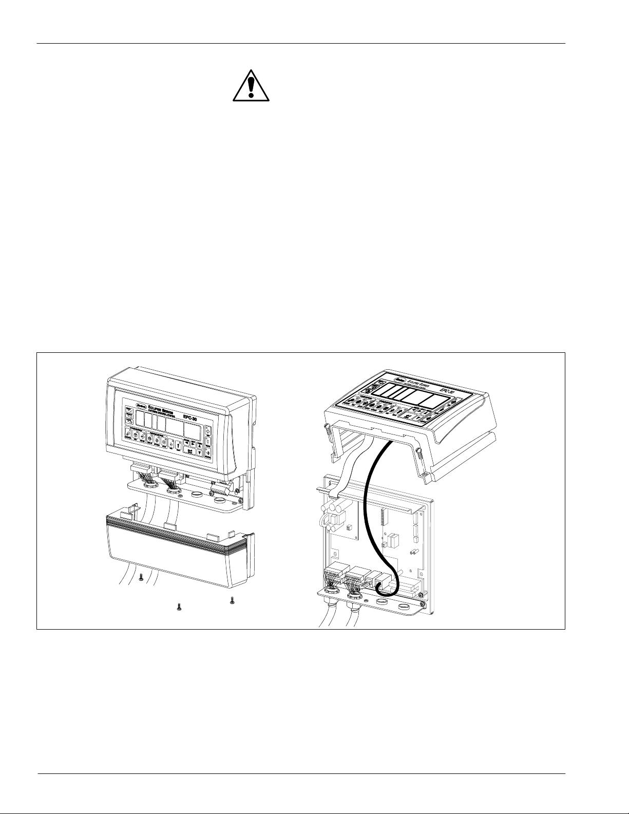
2. See Figure 1. Remove the three screws that secure the terminal
block cover to the unit; then pull the terminal block cover down about
25 mm (1 in.) to disengage the tabs and remove it from the unit.
3. Remove the two screws that secure the operator panel assembly to
the mounting plate.
E 1999 Nordson Corporation
All rights reserved
331 181A
Issued 3/99
Manual 66--EPC30 --IS --06 (formerly 46-442)
Page 2
2
Series EPC-30 Firmware Upgrade Kit
CAUTION: Risk of equipment damage. To prevent damage to
the cables, take care not to move the operator panel assembly
too far from the main control unit.
4. Rotate the bottom of the operator panel assembly up and
a. Disconnect the serial port cable from X5 on the main control
board.
b. Disconnect the wiring harness from X3 on the dc-converter board.
5. Place the operator panel on a clean work surface.
6. If you have a remote operater panel, remove the cover to access the
display board.
NOTE: As an alternative, you can remove the entire pattern control unit
from its mounting location and place it on a clean work surface. If you
choose this option, you will need to disconnect the top halves of the
terminal blocks, disconnect the conduit plate from the mounting plate,
and remove the mounting plate and main control unit from the mounting
location.
Fig. 1 Opening the Pattern Control Unit
Manual 66--EPC30 --IS --06 (formerly 46-442)
331 181A
Issued 3/99
5742090A
E 1999 Nordson Corporation
All rights reserved
Page 3
Series EPC-30 Firmware Upgrade Kit
Rep
laci
ngtheFirmwar
ips
3
eCh
Follow this procedure to replace the firmware chips. Both chips must be
replaced.
CAUTION: Risk of equipment damage. Make sure you are
properly grounded, or touch a grounded a surface, before
performing this procedure. Static discharge can damage the
firmware chips.
1. Make sure you are properly grounded, or touch a grounded surface,
to remove static discharge from your body.
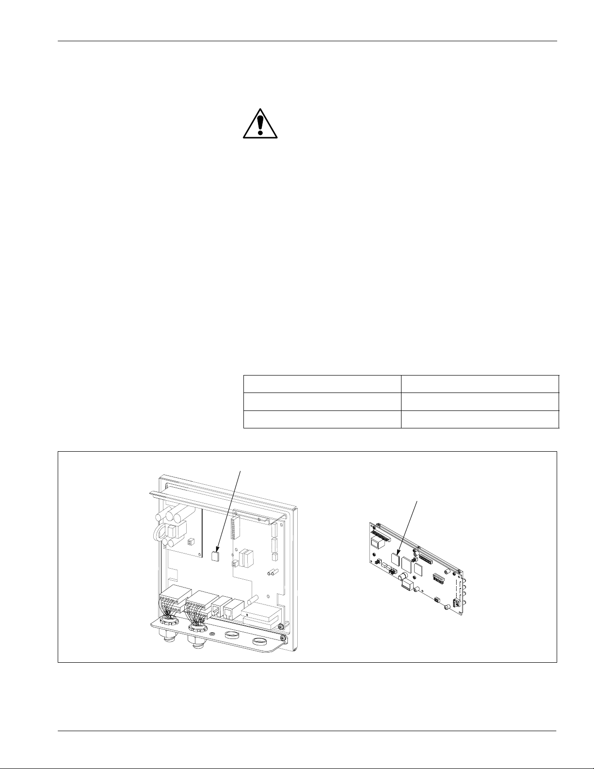
2. See Figure 2. Use the chip removal tool from the service kit to
remove the firmware chips from
S U6 on the main control board (1)
S U3 on the display board (2)
NOTE: If your unit does not have an operater panel, discard the
display board chip.
NOTE: The display board is located behind the operater panel
assembly or the remote operater panel.
3. Install the new chips as directed in the following table. Make sure the
notched corner of the chip is aligned with the notched corner of the
connector.
Chip Part Number
Installation Location
277 837 U6 on the main control board
277 845 U3 on the display board
1
2
5742112A
Fig. 2 Replacing the Firmware Chips
1. Firmware chip on main control board 2. Firmware chip on display board
E 1999 Nordson Corporation
All rights reserved
331 181A
Issued 3/99
Manual 66--EPC30 --IS --06 (formerly 46-442)
Page 4
4
Res
toringtheUnittoNor
mal
t
ion
3
Opera
Series EPC-30 Firmware Upgrade Kit
Follow this procedure to reinstall the operator panel assembly and the
terminal block cover and to restore the unit to normal operation.
1. Hold the operator panel assembly above the main control unit while
you connect the serial port cable to X5 on the main control board and
the wiring harness to X3 on the dc-converter board.
2. Secure the operator panel to the mounting plate using the screws you
removed earlier.
NOTE: If you removed the unit from its mounting location to replace
the firmware chips, then reinstall the unit at its mounting location,
reconnect the top halves of the terminal blocks, and reinstall the
conduit plate.
3. Reinstall the terminal block cover.
4. If you have a remote operater panel, reinstall the cover.
5. Restore power to the unit. Because of the new firmware, the WA IT
message will display for several seconds longer than normal.
.Parts
To order parts, contact the Nordson Customer Service Center or your
local Nordson representative. Use the following parts list to describe
parts correctly.
Part
Description Quantity
772 022 Service kit, firmware —
------ Firmware chip, main control board 1
------ Firmware chip, display board 1
------ Chip removal tool 1
Original copyright date 1999. Nordson and the Nordson logo are registered trademarks of Nordson Corporation.
Manual 66--EPC30 --IS --06 (formerly 46-442)
331 181A
Issued 3/99
E 1999 Nordson Corporation
All rights reserved
 Loading...