


Control System CS 20
for MX / MC Hot Melt Material Applicators
Manual P/N 412 960 D
– English –
NORDSON ENGINEERING GMBH LÜNEBURG GERMANY

P/N 448 513
P/N 449 507
P/N 449 485
P/N 449 509
Note
This manual applies to MX/MC units with CS 20 central units with the following P/N:
P/N = Order number for Nordson products
Order number
Notice
This is a Nordson Corporation publication which is protected by copyright. Original copyright date 1999.
No part of this document may be photocopied, reproduced, or translated to another language without the prior
written consent of Nordson Corporation. The information contained in this publication is subject to change without
notice.
Trademarks
AccuJet, AquaGuard, Asymtek, Automove, Autotech, Blue Box, CF, CanWorks, Century, Clean Coat, CleanSleeve, CleanSpray, Compumelt, Control Coat,
Cross-Cut, Cyclo-Kinetic, Dispensejet, DispenseMate, Durafiber, Durasystem, Easy Coat, Easymove Plus, Econo-Coat, EPREG, ETI, Excel 2000, Flex-O-Coat,
FlexiCoat, Flexi-Spray , Flow Sentry, Fluidmove, FoamMelt, FoamMix, Helix, Horizon, Hose Mole, Hot Shot, Hot Stitch, Isocoil, Isocore, Iso-Flo, JR, KB30, Little Squirt,
Magnastatic, MEG, Meltex, MicroSet, Millenium, Mini Squirt, Moist-Cure, Mountaingate, MultiScan, Nordson, OmniScan, Opticoat, Package of V alues, Pattern View,
PluraFoam, Porous Coat, PowderGrid, Powderware, Pro-Flo, ProLink, Pro-Meter , Pro-Stream, PRX, RBX, Rhino, S. design stylized, Saturn, SC5, Select Charge,
Select Coat, Select Cure, Slautterback, Smart-Coat, Spray Squirt, Spraymelt, Super Squirt, Sure Coat, System Sentry, Tela-Therm, Trends, Tribomatic, UniScan,
UpTime, V eritec, Versa-Coat, Versa-Screen, Versa-Spray, W atermark, When you expect more
ATS, Aerocharge, Auto-Flo, AutoScan, BetterBook, Chameleon, CanNeck, Check Mate, COLORMAX, Control Weave, Controlled Fiberizati on, CPX, E-Nordson,
EasyClean, Eclipse, Equi=Bead, Fillmaster, Gluie, Ink-Dot, Iso-Flex, Kinetix, Maxima, MicroFin, Minimeter, Multifil, OptiMix, PluraMix, Primarc, Prism, Process Sentry,
PurTech, Pulse Spray, Seal Sentry, Select Series, Sensomatic, Shaftshield, Spectral, Spectrum, Sure Brand, Swirl Coat, Vista, Walcom, 2 Rings (Design) are
trademarks – T – of Nordson Corporation.
Designations and trademarks stated in this document may be brands that, when used by third parties for their own purposes,
COV_EN_412960D
could lead to violation of the owners’ rights.
CS03
Issued 07/01
. are registered trademarks – – of Nordson Corporation.
E 2001 Nordson Corporation
All rights reserved

Table of Contents
Table of Contents
I
Overview
1. Safety 1. . . . . . . . . . . . . . . . . . . . . . . . . . . . . . . . . . . . . . . . . . . . . . . . . . . . .
2. Intended Use 1. . . . . . . . . . . . . . . . . . . . . . . . . . . . . . . . . . . . . . . . . . . . . . .
Unintended Use 1. . . . . . . . . . . . . . . . . . . . . . . . . . . . . . . . . . . . . . . . . .
Residual Risks 1. . . . . . . . . . . . . . . . . . . . . . . . . . . . . . . . . . . . . . . . . . .
3. Note on Manual 1. . . . . . . . . . . . . . . . . . . . . . . . . . . . . . . . . . . . . . . . . . . . .
4. PROFIBUS DP 2. . . . . . . . . . . . . . . . . . . . . . . . . . . . . . . . . . . . . . . . . . . . .
General Information 2. . . . . . . . . . . . . . . . . . . . . . . . . . . . . . . . . . . . . . .
Plug Connectors 2. . . . . . . . . . . . . . . . . . . . . . . . . . . . . . . . . . . . . . . . . .
Installation 2. . . . . . . . . . . . . . . . . . . . . . . . . . . . . . . . . . . . . . . . . . . . . . .
Transmission Speed 3. . . . . . . . . . . . . . . . . . . . . . . . . . . . . . . . . . . . . .
Guidelines 3. . . . . . . . . . . . . . . . . . . . . . . . . . . . . . . . . . . . . . . . . . . . . . .
Host 3. . . . . . . . . . . . . . . . . . . . . . . . . . . . . . . . . . . . . . . . . . . . . . . . . .
Definition of Terms 3. . . . . . . . . . . . . . . . . . . . . . . . . . . . . . . . . . . . . . . .
Stand Alone Mode 3. . . . . . . . . . . . . . . . . . . . . . . . . . . . . . . . . . . . . .
Remote Mode 3. . . . . . . . . . . . . . . . . . . . . . . . . . . . . . . . . . . . . . . . . .
5. Control Panel 4. . . . . . . . . . . . . . . . . . . . . . . . . . . . . . . . . . . . . . . . . . . . . . .
6. Control Panel for Double Stream Pumps 5. . . . . . . . . . . . . . . . . . . . . . .
7. Indication Lamps and Indicator Beacon 6. . . . . . . . . . . . . . . . . . . . . . . .
8. Overview of Settings 7. . . . . . . . . . . . . . . . . . . . . . . . . . . . . . . . . . . . . . . . .
Temperature Part 7. . . . . . . . . . . . . . . . . . . . . . . . . . . . . . . . . . . . . . . . .
Motor Part 8. . . . . . . . . . . . . . . . . . . . . . . . . . . . . . . . . . . . . . . . . . . . . . .
E 2001 Nordson Corporation
All rights reserved
CS03
Issued 07/01
P/N 412960D

II
Table of Contents
Operating the Temperature
Part
1. Operation Overview 11. . . . . . . . . . . . . . . . . . . . . . . . . . . . . . . . . . . . . . . .
2. Display Overview 12. . . . . . . . . . . . . . . . . . . . . . . . . . . . . . . . . . . . . . . . . . .
Overview of Parameters Set by Channel 13. . . . . . . . . . . . . . . . . . . .
3. Basic Settings 14. . . . . . . . . . . . . . . . . . . . . . . . . . . . . . . . . . . . . . . . . . . . .
Startup Control with Leading Channel 14. . . . . . . . . . . . . . . . . . . . . .
Temperature Display, Selecting Celsius or Fahrenheit 14. . . . . . . .
Switching Scan Mode On/Off 14. . . . . . . . . . . . . . . . . . . . . . . . . . . . . .
Selecting Control or Measuring Mode 15. . . . . . . . . . . . . . . . . . . . . . .
Switching Channel On/Off 15. . . . . . . . . . . . . . . . . . . . . . . . . . . . . . . . .
4. Switching Immediate Temperature Setback On/Off 16. . . . . . . . . . . . .
5. Setting Temperature 16. . . . . . . . . . . . . . . . . . . . . . . . . . . . . . . . . . . . . . . .
6. Setting Parameters 17. . . . . . . . . . . . . . . . . . . . . . . . . . . . . . . . . . . . . . . . .
Setting Parameters by Channel 17. . . . . . . . . . . . . . . . . . . . . . . . . . . .
Example of Selecting Parameter Set 17. . . . . . . . . . . . . . . . . . . . .
Return Parameter to Factory Setting 17. . . . . . . . . . . . . . . . . . . . . . .
Parameter Overview 18. . . . . . . . . . . . . . . . . . . . . . . . . . . . . . . . . . . . .
SPL = Setback Temperature 18. . . . . . . . . . . . . . . . . . . . . . . . . . . .
h SPL = Setback Period 18. . . . . . . . . . . . . . . . . . . . . . . . . . . . . . .
Co OFF = Inert Gas Interval 18. . . . . . . . . . . . . . . . . . . . . . . . . . . .
Co On = Inert Gas Injection Period 18. . . . . . . . . . . . . . . . . . . . . . .
t1 = Control Mode 18. . . . . . . . . . . . . . . . . . . . . . . . . . . . . . . . . . . . .
Lo = Undertemperature Value/Interlock 19. . . . . . . . . . . . . . . . . . .
Hi = Overtemperature Value 19. . . . . . . . . . . . . . . . . . . . . . . . . . . .
OFF = Overtemperature Shutdown 19. . . . . . . . . . . . . . . . . . . . . .
Pid = Predefined Control Parameters 19. . . . . . . . . . . . . . . . . . . .
On = Regulation Ratio (Display) 20. . . . . . . . . . . . . . . . . . . . . . . . .
SE = Service Display 20. . . . . . . . . . . . . . . . . . . . . . . . . . . . . . . . . . .
7. Automatic Fault Displays 20. . . . . . . . . . . . . . . . . . . . . . . . . . . . . . . . . . . .
8. Bar Graph (Option) 22. . . . . . . . . . . . . . . . . . . . . . . . . . . . . . . . . . . . . . . . .
P/N 412960D
CS03
Issued 07/01
E 2001 Nordson Corporation
All rights reserved

Table of Contents
III
Operating the Motor Part
1. Operation Overview 24. . . . . . . . . . . . . . . . . . . . . . . . . . . . . . . . . . . . . . . .
2. Display Overview 25. . . . . . . . . . . . . . . . . . . . . . . . . . . . . . . . . . . . . . . . . . .
3. Pressure Control 27. . . . . . . . . . . . . . . . . . . . . . . . . . . . . . . . . . . . . . . . . . .
4. Basic Settings 28. . . . . . . . . . . . . . . . . . . . . . . . . . . . . . . . . . . . . . . . . . . . .
Selecting Manual or Automatic Mode 28. . . . . . . . . . . . . . . . . . . . . . .
Selecting Pressure Display (Option) bar or psi 28. . . . . . . . . . . . . . .
5. T est 29. . . . . . . . . . . . . . . . . . . . . . . . . . . . . . . . . . . . . . . . . . . . . . . . . . . . . .
6. Switching ON Motor(s) 29. . . . . . . . . . . . . . . . . . . . . . . . . . . . . . . . . . . . . .
Motor Startup Protection 29. . . . . . . . . . . . . . . . . . . . . . . . . . . . . . . . . .
7. Switching OFF Motor(s) 30. . . . . . . . . . . . . . . . . . . . . . . . . . . . . . . . . . . . .
Switch Off one Motor 30. . . . . . . . . . . . . . . . . . . . . . . . . . . . . . . . . . . . .
Switch Off all Motors 30. . . . . . . . . . . . . . . . . . . . . . . . . . . . . . . . . . . . .
8. Set Speed (Manual Mode) 30. . . . . . . . . . . . . . . . . . . . . . . . . . . . . . . . . . .
9. Setting Speed (Automatic Mode) 31. . . . . . . . . . . . . . . . . . . . . . . . . . . . .
Speed Parameters in Automatic Mode 31. . . . . . . . . . . . . . . . . . . . . .
10. Switching Automatic Temperature Setback ON/OFF 33. . . . . . . . . . . .
11. Setting Parameters 33. . . . . . . . . . . . . . . . . . . . . . . . . . . . . . . . . . . . . . . . .
Return Parameter to Factory Setting 33. . . . . . . . . . . . . . . . . . . . . . .
Parameter Overview 34. . . . . . . . . . . . . . . . . . . . . . . . . . . . . . . . . . . . .
rLo = Motor Speed at 0 % Pilot Voltage 34. . . . . . . . . . . . . . . . . . .
rhi = Motor Speed at Pilot Voltage Uhi 34. . . . . . . . . . . . . . . . . . . .
Uhi = Pilot Voltage
at which the Motor Rotates Constantly at rhi 34. . . . . . . . . . . . . .
rLo, rhi and Uhi, Graphic Illustration 34. . . . . . . . . . . . . . . . . . . . . .
PSH = Pressure at Pilot V oltage Uhi 35. . . . . . . . . . . . . . . . . . . . .
PSL = Pressure at 0 % Pilot Voltage 35. . . . . . . . . . . . . . . . . . . . .
PSP = Pressure Setpoint (Manual Mode) 35. . . . . . . . . . . . . . . . .
PSL, PSH and Uhi, Graphic Illustration 35. . . . . . . . . . . . . . . . . . .
PAH = Pressure Monitoring
for Overpressure (when Pressure Controlled) 36. . . . . . . . . . . . .
PAL = Pressure Monitoring
for Underpressure (when Pressure Controlled) 36. . . . . . . . . . . .
E 2001 Nordson Corporation
All rights reserved
CS03
Issued 07/01
P/N 412960D

IV
Table of Contents
Operating the Motor Part
(contd.)
SPL = Temperature Setback after Motor Standstill 36. . . . . . . . .
PdS = Second Display for Double Stream Pumps 36. . . . . . . . . .
PrS = Variable Pressure Measuring Range 37. . . . . . . . . . . . . . .
Plo = Pressure Monitoring for Underpressure 37. . . . . . . . . . . . .
Phi = Pressure Monitoring for Overpressure 37. . . . . . . . . . . . . . .
SLo = Threshold Value Switch, Lower Value 38. . . . . . . . . . . . . .
Shi = Threshold Value Switch, Upper Value 38. . . . . . . . . . . . . . .
SLo and Shi, Graphic Illustration 38. . . . . . . . . . . . . . . . . . . . . . . . .
drS = Reverse Speed 38. . . . . . . . . . . . . . . . . . . . . . . . . . . . . . . . . .
drt = Reverse Time 38. . . . . . . . . . . . . . . . . . . . . . . . . . . . . . . . . . . .
rPU = Adapting Speed to Special Gearbox 39. . . . . . . . . . . . . . . .
r_d = Limiting Value for Speed Alarm 39. . . . . . . . . . . . . . . . . . . . .
Adr = Field Bus Address of Unit 39. . . . . . . . . . . . . . . . . . . . . . . . .
CoF = Inert Gas Control (Interval) 40. . . . . . . . . . . . . . . . . . . . . . .
Con = Inert Gas Control (Injection Period) 40. . . . . . . . . . . . . . . .
C1 = Forcibly Actuated Inert Gas Injection 40. . . . . . . . . . . . . . . .
C2 = Forcibly Actuated Air Exhaust (Vacuum Pump) 40. . . . . . .
12. Service Displays 41. . . . . . . . . . . . . . . . . . . . . . . . . . . . . . . . . . . . . . . . . . .
Service Displays di and do 43. . . . . . . . . . . . . . . . . . . . . . . . . . . . . . . .
Code of DIP Switch S 6 43. . . . . . . . . . . . . . . . . . . . . . . . . . . . . . . . . . .
Service Display Error 44. . . . . . . . . . . . . . . . . . . . . . . . . . . . . . . . . . . . .
P/N 412960D
CS03
Issued 07/01
E 2001 Nordson Corporation
All rights reserved

Table of Contents
V
Technical Appendix of the
Temperature Part
1. Diagnosis Program 51. . . . . . . . . . . . . . . . . . . . . . . . . . . . . . . . . . . . . . . . .
Activating the Diagnosis Program 52. . . . . . . . . . . . . . . . . . . . . . . . . .
Test phase 0 52. . . . . . . . . . . . . . . . . . . . . . . . . . . . . . . . . . . . . . . . . . . .
Test Phases 1 to n 53. . . . . . . . . . . . . . . . . . . . . . . . . . . . . . . . . . . . . . .
Ending the Diagnosis Program 54. . . . . . . . . . . . . . . . . . . . . . . . . . . .
2. Correcting Temperature Sensors 54. . . . . . . . . . . . . . . . . . . . . . . . . . . . .
3. Temperature Control Panel Board 55. . . . . . . . . . . . . . . . . . . . . . . . . . . .
Fuses 55. . . . . . . . . . . . . . . . . . . . . . . . . . . . . . . . . . . . . . . . . . . . . . . . . .
LED’s 55. . . . . . . . . . . . . . . . . . . . . . . . . . . . . . . . . . . . . . . . . . . . . . . . . .
DIP Switch S 7 56. . . . . . . . . . . . . . . . . . . . . . . . . . . . . . . . . . . . . . . . . .
DIP Switch S 8 56. . . . . . . . . . . . . . . . . . . . . . . . . . . . . . . . . . . . . . . . . .
DIP Switch S 8, Switch 6 57. . . . . . . . . . . . . . . . . . . . . . . . . . . . . . . . . .
Plug Connectors 57. . . . . . . . . . . . . . . . . . . . . . . . . . . . . . . . . . . . . . . . .
4. Temperature Control Module 58. . . . . . . . . . . . . . . . . . . . . . . . . . . . . . . . .
Fe-CuNi 58. . . . . . . . . . . . . . . . . . . . . . . . . . . . . . . . . . . . . . . . . . . . . . . .
Pt 100, Ni 120 59. . . . . . . . . . . . . . . . . . . . . . . . . . . . . . . . . . . . . . . . . . .
LED’s 60. . . . . . . . . . . . . . . . . . . . . . . . . . . . . . . . . . . . . . . . . . . . . . . . . .
Plug Connectors 61. . . . . . . . . . . . . . . . . . . . . . . . . . . . . . . . . . . . . . . . .
Selector Switch S 1 62. . . . . . . . . . . . . . . . . . . . . . . . . . . . . . . . . . . . . .
DIP Switch S 2 62. . . . . . . . . . . . . . . . . . . . . . . . . . . . . . . . . . . . . . . . . .
DIP Switch S 3 62. . . . . . . . . . . . . . . . . . . . . . . . . . . . . . . . . . . . . . . . . .
Potentiometer P 1 62. . . . . . . . . . . . . . . . . . . . . . . . . . . . . . . . . . . . . . . .
Switch S 62. . . . . . . . . . . . . . . . . . . . . . . . . . . . . . . . . . . . . . . . . . . . . . . .
5. Voltage Control of Temperature Control Module 63. . . . . . . . . . . . . . . .
Fuses 63. . . . . . . . . . . . . . . . . . . . . . . . . . . . . . . . . . . . . . . . . . . . . . . . . .
LED’s 63. . . . . . . . . . . . . . . . . . . . . . . . . . . . . . . . . . . . . . . . . . . . . . . . . .
Plug Connectors 63. . . . . . . . . . . . . . . . . . . . . . . . . . . . . . . . . . . . . . . . .
E 2001 Nordson Corporation
All rights reserved
CS03
Issued 07/01
P/N 412960D

VI
Table of Contents
Technical Appendix of the
Temperature Part
(contd.)
6. Bar Graph (Option) 64. . . . . . . . . . . . . . . . . . . . . . . . . . . . . . . . . . . . . . . . .
Fuses 64. . . . . . . . . . . . . . . . . . . . . . . . . . . . . . . . . . . . . . . . . . . . . . . . . .
LED’s 64. . . . . . . . . . . . . . . . . . . . . . . . . . . . . . . . . . . . . . . . . . . . . . . . . .
Plug Connectors 65. . . . . . . . . . . . . . . . . . . . . . . . . . . . . . . . . . . . . . . . .
Selector Switch S 2 65. . . . . . . . . . . . . . . . . . . . . . . . . . . . . . . . . . . . . .
DIP Switch S 1 65. . . . . . . . . . . . . . . . . . . . . . . . . . . . . . . . . . . . . . . . . .
DIP Switch S 3 66. . . . . . . . . . . . . . . . . . . . . . . . . . . . . . . . . . . . . . . . . .
Basic Settings (Switches 1 and 2) 66. . . . . . . . . . . . . . . . . . . . . . .
Setting Deviation Values (Switches 3 to 8) 66. . . . . . . . . . . . . . . .
7. Temperature Comparison Measuring Point 67. . . . . . . . . . . . . . . . . . . .
P/N 412960D
CS03
Issued 07/01
E 2001 Nordson Corporation
All rights reserved

Table of Contents
VII
Technical Appendix of the
Motor Part
1. Central Module with Digital Input/Output 69. . . . . . . . . . . . . . . . . . . . . . .
2. Central Module 69. . . . . . . . . . . . . . . . . . . . . . . . . . . . . . . . . . . . . . . . . . . .
Fuses 69. . . . . . . . . . . . . . . . . . . . . . . . . . . . . . . . . . . . . . . . . . . . . . . . . .
LED’s 70. . . . . . . . . . . . . . . . . . . . . . . . . . . . . . . . . . . . . . . . . . . . . . . . . .
Potentiometer R 18, R 42 70. . . . . . . . . . . . . . . . . . . . . . . . . . . . . . . . .
DIP Switch S 1 70. . . . . . . . . . . . . . . . . . . . . . . . . . . . . . . . . . . . . . . . . .
DIP Switch S 6 71. . . . . . . . . . . . . . . . . . . . . . . . . . . . . . . . . . . . . . . . . .
Button S 3 71. . . . . . . . . . . . . . . . . . . . . . . . . . . . . . . . . . . . . . . . . . . . . .
Switch S 2 71. . . . . . . . . . . . . . . . . . . . . . . . . . . . . . . . . . . . . . . . . . . . . .
Switch S 15 71. . . . . . . . . . . . . . . . . . . . . . . . . . . . . . . . . . . . . . . . . . . . .
Plug Connectors 72. . . . . . . . . . . . . . . . . . . . . . . . . . . . . . . . . . . . . . . . .
Aligning Pilot Voltage 74. . . . . . . . . . . . . . . . . . . . . . . . . . . . . . . . . . . . .
Aligning Pilot Voltage Input 0 to 10 VDC 74. . . . . . . . . . . . . . . . . .
Aligning Pilot Voltage Input 0 to 160 VDC 74. . . . . . . . . . . . . . . . .
3. Digital Module 75. . . . . . . . . . . . . . . . . . . . . . . . . . . . . . . . . . . . . . . . . . . . .
Fuses 75. . . . . . . . . . . . . . . . . . . . . . . . . . . . . . . . . . . . . . . . . . . . . . . . . .
LED’s 75. . . . . . . . . . . . . . . . . . . . . . . . . . . . . . . . . . . . . . . . . . . . . . . . . .
DIP Switch S 12 75. . . . . . . . . . . . . . . . . . . . . . . . . . . . . . . . . . . . . . . . .
Selector Switch S 11 76. . . . . . . . . . . . . . . . . . . . . . . . . . . . . . . . . . . . .
Plug Connectors 76. . . . . . . . . . . . . . . . . . . . . . . . . . . . . . . . . . . . . . . . .
Function of Input Signals 80. . . . . . . . . . . . . . . . . . . . . . . . . . . . . . . . . .
Function of Output Signals 84. . . . . . . . . . . . . . . . . . . . . . . . . . . . . . . .
Fuses (Separate Digital Module) 87. . . . . . . . . . . . . . . . . . . . . . . . . . .
LED’s (Separate Digital Module) 88. . . . . . . . . . . . . . . . . . . . . . . . . . .
DIP Switch S 2 (Separate Digital Module) 88. . . . . . . . . . . . . . . . . . .
Selector Switch S 1 (Separate Digital Module) 88. . . . . . . . . . . . . . .
Plug Connectors X1 to X5 (Separate Digital Module) 88. . . . . . . . .
Plug Connectors (MC Standard Units) 89. . . . . . . . . . . . . . . . . . . . . .
Function of Input Signals (MC Standard Units) 90. . . . . . . . . . . . . . .
Function of Output Signals (MC Standard Units) 91. . . . . . . . . . . . .
E 2001 Nordson Corporation
All rights reserved
CS03
Issued 07/01
P/N 412960D

VIII
Table of Contents
Technical Appendix of the
Motor Part
(contd.)
4. Field Bus Communication Module 92. . . . . . . . . . . . . . . . . . . . . . . . . . . .
LED’s 92. . . . . . . . . . . . . . . . . . . . . . . . . . . . . . . . . . . . . . . . . . . . . . . . . .
PROFIBUS Plug Connectors 92. . . . . . . . . . . . . . . . . . . . . . . . . . . . . .
5. Motor Control Panel Board 93. . . . . . . . . . . . . . . . . . . . . . . . . . . . . . . . . .
Fuses 93. . . . . . . . . . . . . . . . . . . . . . . . . . . . . . . . . . . . . . . . . . . . . . . . . .
LED’s 93. . . . . . . . . . . . . . . . . . . . . . . . . . . . . . . . . . . . . . . . . . . . . . . . . .
DIP Switch S 1 94. . . . . . . . . . . . . . . . . . . . . . . . . . . . . . . . . . . . . . . . . .
DIP Switch S 2 94. . . . . . . . . . . . . . . . . . . . . . . . . . . . . . . . . . . . . . . . . .
Plug Connectors 94. . . . . . . . . . . . . . . . . . . . . . . . . . . . . . . . . . . . . . . . .
6. Analog Module 96. . . . . . . . . . . . . . . . . . . . . . . . . . . . . . . . . . . . . . . . . . . . .
Fuses 96. . . . . . . . . . . . . . . . . . . . . . . . . . . . . . . . . . . . . . . . . . . . . . . . . .
LED’s 96. . . . . . . . . . . . . . . . . . . . . . . . . . . . . . . . . . . . . . . . . . . . . . . . . .
Potentiometer R 48 96. . . . . . . . . . . . . . . . . . . . . . . . . . . . . . . . . . . . . .
Potentiometer R 48 97. . . . . . . . . . . . . . . . . . . . . . . . . . . . . . . . . . . . . .
DIP Switch S 2 97. . . . . . . . . . . . . . . . . . . . . . . . . . . . . . . . . . . . . . . . . .
Selector Switch S 1 97. . . . . . . . . . . . . . . . . . . . . . . . . . . . . . . . . . . . . .
Jumper S 3 to S 10 97. . . . . . . . . . . . . . . . . . . . . . . . . . . . . . . . . . . . . . .
Plug Connectors 98. . . . . . . . . . . . . . . . . . . . . . . . . . . . . . . . . . . . . . . . .
7. Level Monitoring 100. . . . . . . . . . . . . . . . . . . . . . . . . . . . . . . . . . . . . . . . . .
Analog Inputs with Digital Function 100. . . . . . . . . . . . . . . . . . . . . . . .
Interlinking of Alarms when Level Fault Occurs 100. . . . . . . . . . . . .
Messages 100. . . . . . . . . . . . . . . . . . . . . . . . . . . . . . . . . . . . . . . . . . . . . .
Plug Connectors 100. . . . . . . . . . . . . . . . . . . . . . . . . . . . . . . . . . . . . . . .
8. Motor Module 101. . . . . . . . . . . . . . . . . . . . . . . . . . . . . . . . . . . . . . . . . . . . .
Fuses 101. . . . . . . . . . . . . . . . . . . . . . . . . . . . . . . . . . . . . . . . . . . . . . . . .
LED’s 101. . . . . . . . . . . . . . . . . . . . . . . . . . . . . . . . . . . . . . . . . . . . . . . . .
DIP Switch S 2 102. . . . . . . . . . . . . . . . . . . . . . . . . . . . . . . . . . . . . . . . .
Selector Switch S 1 102. . . . . . . . . . . . . . . . . . . . . . . . . . . . . . . . . . . . .
Switch S 3 102. . . . . . . . . . . . . . . . . . . . . . . . . . . . . . . . . . . . . . . . . . . . .
Potentiometer R 8 102. . . . . . . . . . . . . . . . . . . . . . . . . . . . . . . . . . . . . . .
P/N 412960D
Potentiometer R 36 102. . . . . . . . . . . . . . . . . . . . . . . . . . . . . . . . . . . . .
Plug Connectors 102. . . . . . . . . . . . . . . . . . . . . . . . . . . . . . . . . . . . . . . .
Aligning the Motor Module 105. . . . . . . . . . . . . . . . . . . . . . . . . . . . . . .
CS03
Issued 07/01
E 2001 Nordson Corporation
All rights reserved

Overview
Control system CS 20
1
1. Safety
2. Intended Use
Unintended Use
WARNING: Allow only qualified personnel to perform the
following tasks. Observe and follow the safety instructions in
this document and all other related documentation.
The control system may only be used to regulate and control Nordson
units/systems. The values stated under
the unit/system (temperatures, speeds, etc.) must be complied with.
Nordson will grant no warranty and assume no liability for damage
resulting from incorrect settings.
Any other use is considered to be unintended. Nordson will assume no
liability for personal injury or property damage resulting from unintended
use.
Intended use includes the observance of Nordson safety regulations.
The control system may not be used under the following conditions:
Specifications
in the manual for
S In defective condition
S In a potentially explosive atmosphere
Residual Risks
3. Note on Manual
S When unauthorized changes or modifications have been made by the
customer
S By an electrostatically charged person.
Nordson knows of no residual risks.
This manual applies to
S The control system
S The control system
CS 20
CS 20
with
PROFIBUS DP.
E 2001 Nordson Corporation
All rights reserved
CS03
Issued 07/01
P/N 412960D

2
Control system CS 20
4. PROFIBUS DP
General Information
Plug Connectors
When a control system
CS 20
without PROFIBUS interface is used, this
chapter can be ignored.
For the control system
documents
Communication Data List
CS 20
with
PROFIBUS DP
and
, also refer to separate
Field Bus Interface PROFIBUS
DP.
PROFIBUS DP uses the master-slave access method (Refer to
EN 50170). Nordson units on the PROFIBUS are always slaves.
Each unit on the PROFIBUS needs a field bus address for communication purposes. Each address may be assigned only once in the field
bus. The address of the Nordson unit is set on the motor control panel
with the parameter
Also refer to
Module, PROFIBUS Plug Connectors
ADR
.
Technical Appendix of Motor Part, Field Bus Communication
.
The PROFIBUS interface plug connectors are located on the clear cover
of the central module.
With the control system CS 20, the cable screen is linked to protective
grounding / functional grounding with the plug connector X 22.
Installation
Two-wire connection according to EIA-RS 485.
Line A (usually green) and line B (usually red) must be the same on the
entire bus.
To ensure smooth operation, the field bus must end with an active bus
terminator (terminating resistors) at the beginning and the end of a
PROFIBUS segment.
We recommend attaching both sides of the bus cable screen to
protective grounding / functional grounding. When the potential is not the
same at both ends, an equipotential bonding conductor should be laid.
P/N 412960D
CS03
Issued 07/01
E 2001 Nordson Corporation
All rights reserved

Control system CS 20
T
3
ransmission Speed
Guidelines
Definition of Terms
To minimize electromagnetic compatibility disruptions, the lowest possible
Baud rate should be selected. Recommendation: 1500 kBaud.
For additional information, also refer to
Guidelines PROFIBUS DP/FMS
Nutzerorganisation e. V. (user organization).
, published by the PROFIBUS
PROFIBUS Guideline, Setup
Host
Customer’s higher-order control unit, also called
In conjunction with the option
remote
mode switch, also refer to separate manual/supplement for the unit and
to the wiring diagram.
When the mode is changed, activation of the startup protection causes all
of the drives to stop.
are available. For information on changing the mode using the
PROFIBUS DP
master
, the modes
.
stand alone
and
Stand Alone Mode
Stand alone mode is used mainly to visualize data for maintenance and
repair purposes. The unit is operated just like a unit without PROFIBUS:
S Control access only from control panel and from external control
signals via an interface
S Parameter input only via control panel
S On the host, all parameters can be displayed but not changed. The
host can read actual values.
Remote Mode
In remote mode, the host controls the unit:
S Control access only from host
S Parameter input only via host
S On the control panel, all parameters can be displayed but not
changed. Actual values are shown on the control panel.
E 2001 Nordson Corporation
All rights reserved
CS03
Issued 07/01
P/N 412960D
4
Control system CS 20
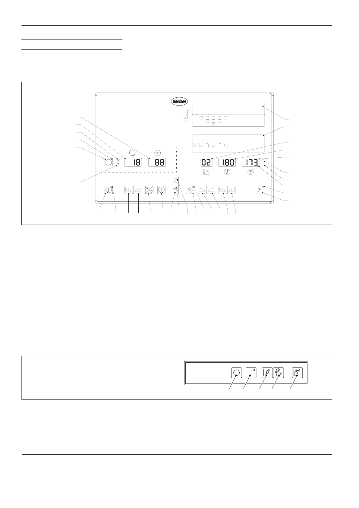
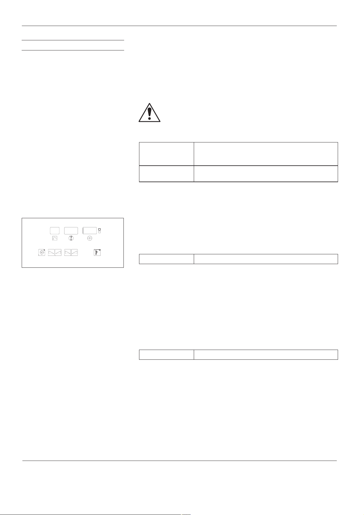
5. Control Panel
31
30
29
28
27
Motor panel
26
M1
The control panel is divided into motor and temperature parts. The
elements found in the dotted line box are also referred to as the
panel
in the following description (up to 6 motor panels per control
motor
system are possible). The motor/pump speed is indicated with the SI-unit
min
-1
(equivalent to rpm).
Motor part Temperature part
1 23 546
R
1
2
1234
n
min
–1
min
bar
x10 psi
56
2
1
2
1
3
4
C
F
5
6
7
8
9
10
Fig. 1
1. Bar graph (option)
2. Channel allocation
3. Display
4. Display
5. Display
Temperature channels
Temperature setpoint
Actual temperature
6. Illuminated symbol
!" "$" (°C)
7. Illuminated symbol !"
!# (°F)
8. Decimal point #
9. LED !#$! "#
10. Key
Temperature setback on/off
1 1. Key !" %$"
Only MC units
Refer to separate unit manual
for key description
25
24
23
22
21
20 19 18
17 161514
12. Key !" %$"
13. Key $
14. Key &
15. LED #! '
16. Enter key
17. Indication lamp #% $# (red)
18. Indication lamp &# (white)
19. Indication lamp ' (green)
20. Key "#
21. Key $$##
22. Key !" #! $ "
131211
23. Key !" #! $ "
24. LED #!"
25. Key #!"
26. Illuminated symbol $
27. Key
Motor pre-selection
28. LED #! !("#
29. Illuminated symbol #!
30. Display #!$ "
31. Display !""$! #
1 2 3 4 5
MXCO001L084A0195
002159
Fig. 2 Additional control panel MC
1. Key
Heating off
2. Key
Heating on
P/N 412960D
3. Illuminated symbol
4. Key
Purge
(inert gas flush)
CS03
Issued 07/01
Inert gas supply
5. Illuminated symbol
empty
Inert gas bottle
E 2001 Nordson Corporation
All rights reserved

Control system CS 20
5
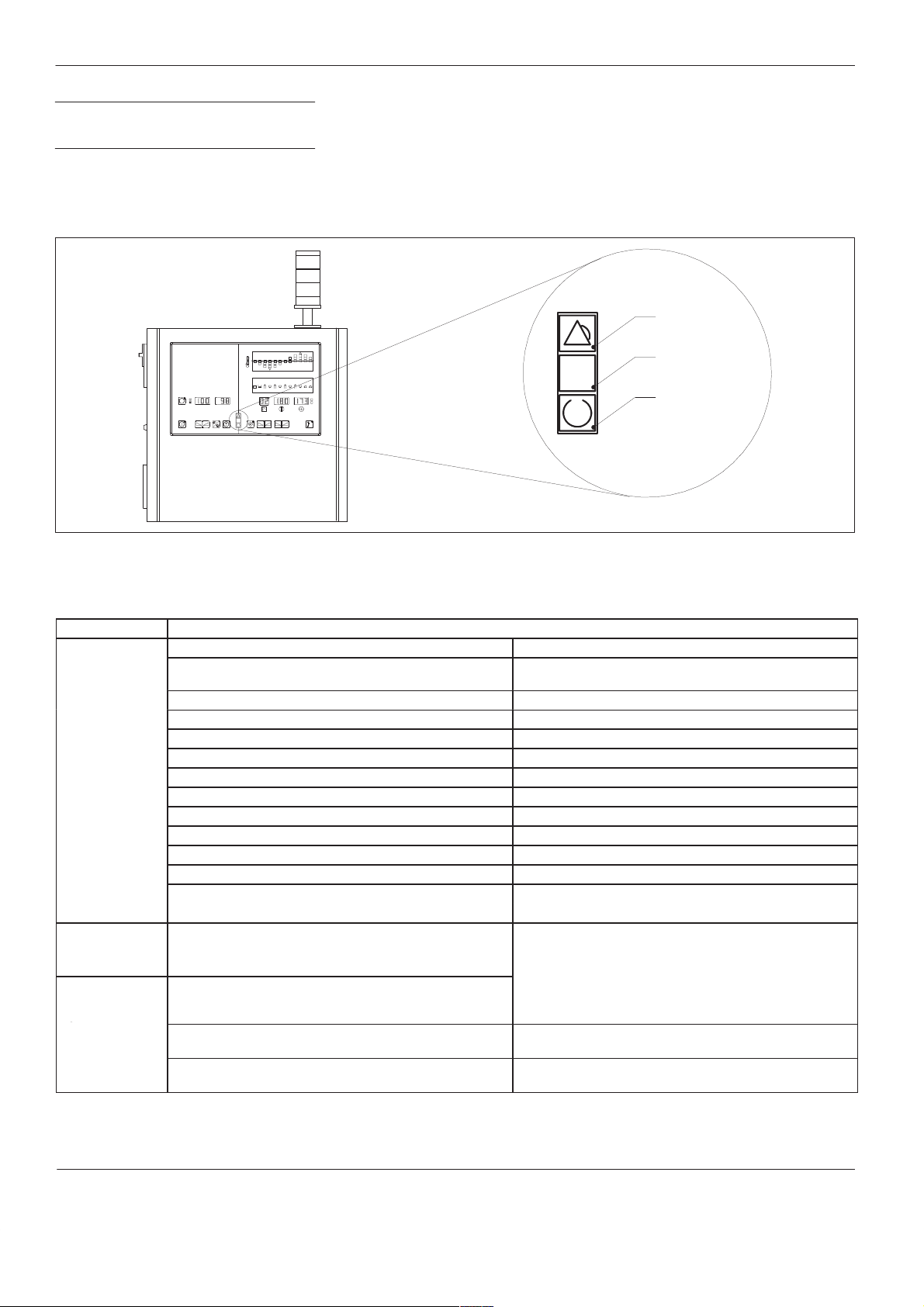
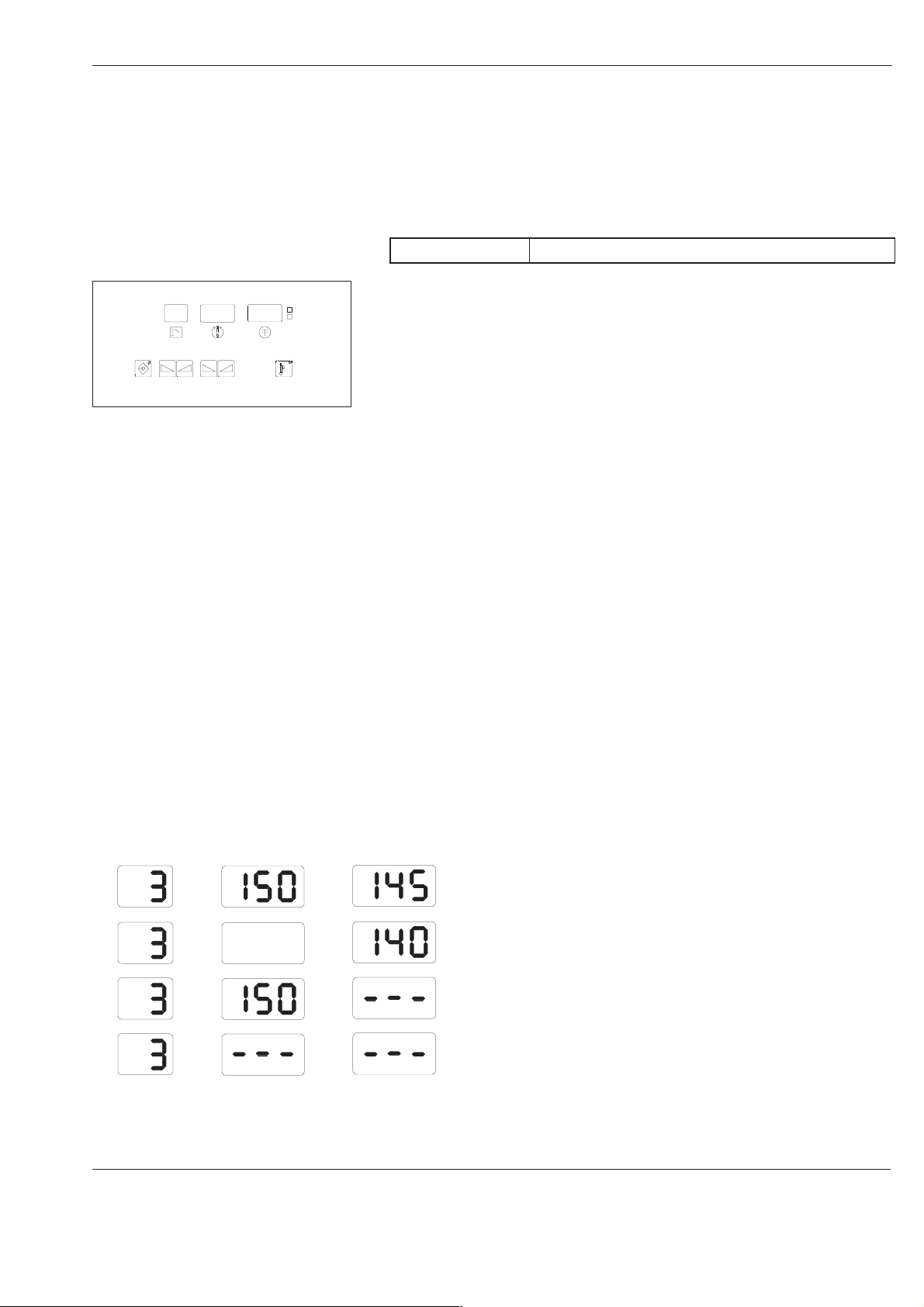
6. Control Panel for Double
Stream Pumps
A pressure sensor can be installed for each pump stream. The control
system offers the option of displaying both pump stream pressures.
There are two display lines for each motor on the motor control panel
(Fig. 3). In the second line of each display, the pressure of the second
pump stream and all parameters relevant for this pump stream are
shown.
3027 31
29
min
–1
bar
psi
26
bar
psi
25
23
22
21 20
002353
Fig. 3 Motor control panel for 1 motor
If the system contains a control panel for double stream pumps, the
software automatically activates the functions needed for the double
stream pumps. If the system uses an analog module to compile pressure,
both pressure displays are activated for each motor.
E 2001 Nordson Corporation
All rights reserved
CS03
Issued 07/01
P/N 412960D
6
o
Control system CS 20
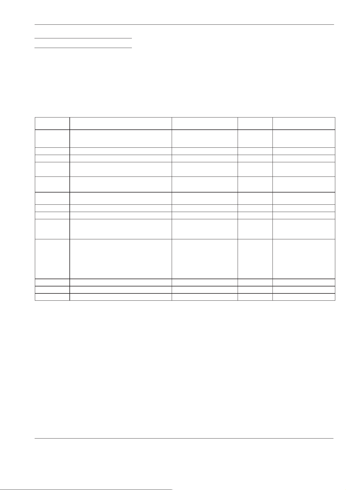
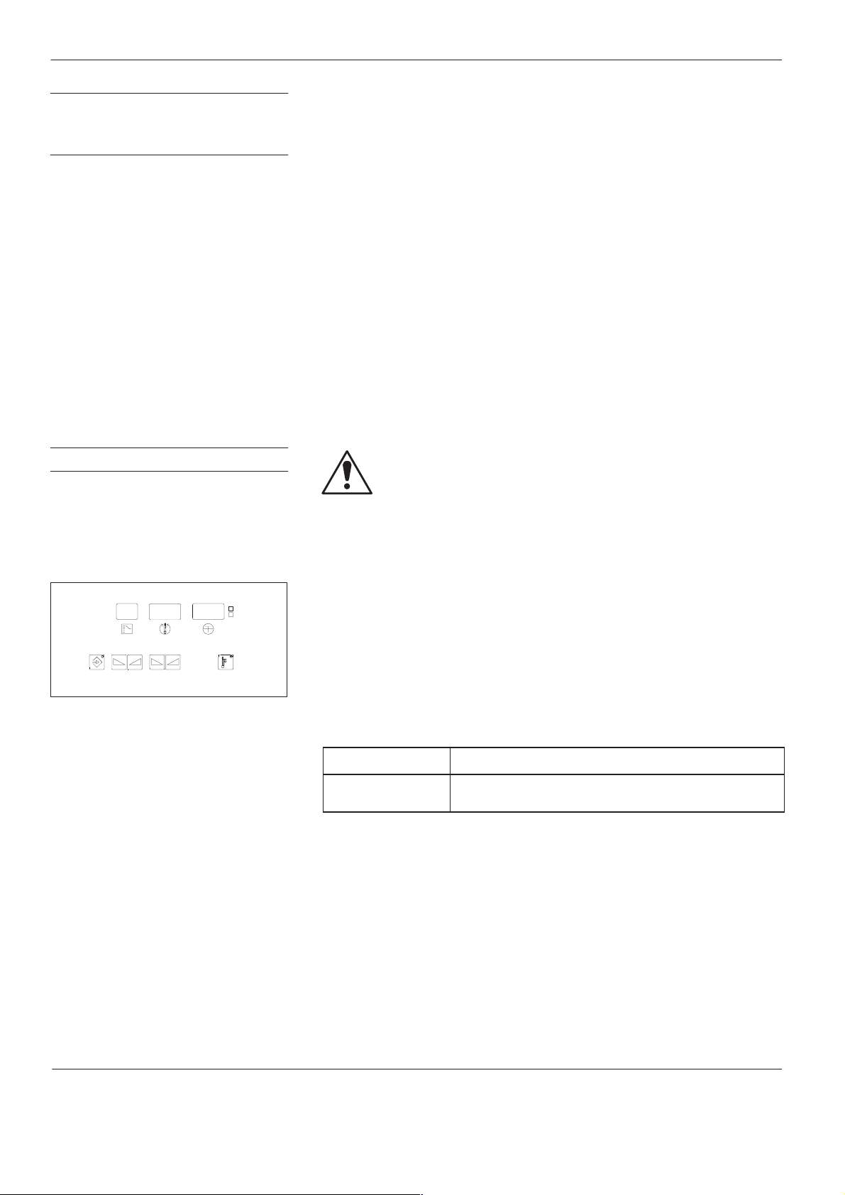
7. Indication Lamps and
Indicator Beacon
1
23 5476
8 9101112
123 5467
8 1091112
3 4
21
11223
M1
psi
bar
–1
min
Fig. 4 (Also refer to Fig. 1 for position numbers)
4
C
F
The indication lamps and the optional indicator beacon show the
operating modes:
Collective fault, Switched on
and
Ready for operation.
The switching of the indicator beacon is carried out differently depending
on the unit series. For certain series and special versions, the indicator
beacon may contain further lamps. The functioning is described in the
manual for the unit/system.
Red
17
White
18
19
Green
MXCO054L067A1295
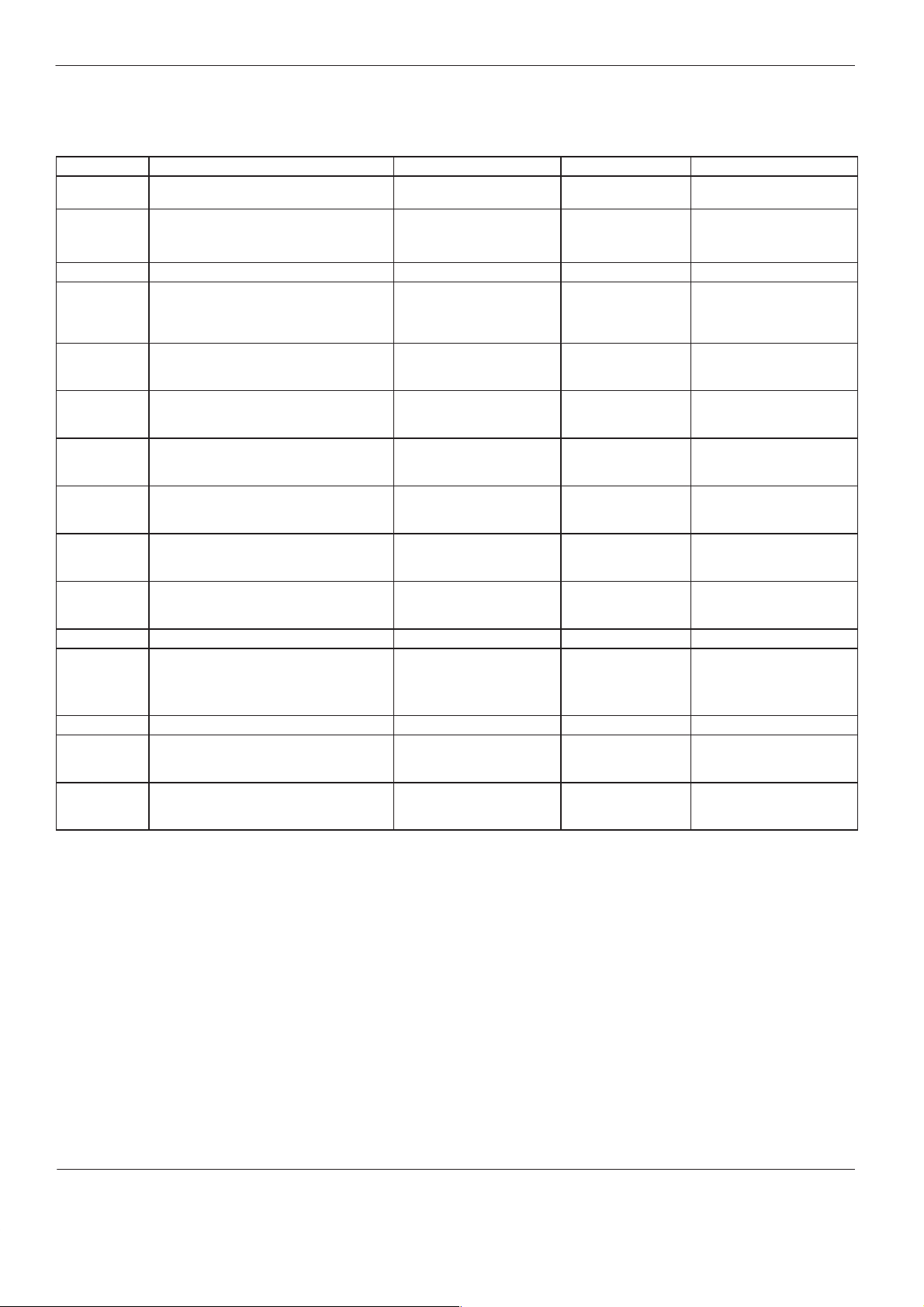
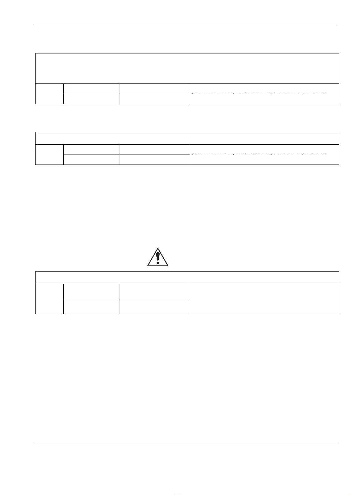
Indication lamp Message(s) Notes
Red (17) Overtemperature message from control system
Collective fault
Overtemperature shutdown by control system,
Display 5: Hi blinking
Displays 3, 4 and 5: 2 ––– ––– blinking
e.g. channel 2
Undertemperature during operation
Ambient temperature too high
Temperature sensor short circuit
Display 5: Lo blinking
Displays 3, 4 and 5: AM bIE nT blinking
Display 5: -S- blinking
Temperature sensor interruption Display 5: – E – blinking
Speed alarm (special function)
Memory error
Coupling fault (special function)
Underpressure alarm (special function)
Display 30: r_d indicated
Displays 4 and 5: blinking
Display 30: indicated
Display 30: indicated
Overpressure alarm (special function) Display 30:
Safety valve opened (special function)
Display 30: indicated
Other error messages Display 30:
Display 31: Error number indicated
If, after the initial heating phase (1 hour and longer), the
green indication lamp is not lit: Refer to manual ,
section
Refer to manual , section
White (18)
Switched on
Green (19)
Ready for opera-
tion
(Refer to service display Error)
After switching on the unit and during the initial heating
phase, only the white indication lamp is lit
The green indication lamp does not light until all channels
have reached their temperature setpoints and when the following conditions have been met:
Release Unit must be bridged or activated
Temperature setback may not be switched on
Refer to section in this manual and to
section in the manual
Phi
indicated
Err
indicated
.
P/N 412960D
CS03
Issued 07/01
E 2001 Nordson Corporation
All rights reserved
Control system CS 20
T
7
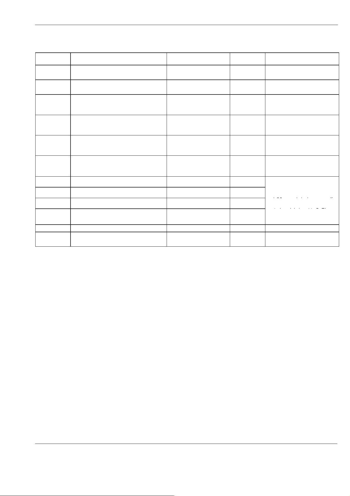
8. Overview of Settings
The possible settings and parameters described here are not available
for every unit/system (Refer to column
The indexes in the column
Notes
Notes
indicate the corresponding position in
the separate communication data list. These references can be ignored
when a control system CS 20 without PROFIBUS is used.
– – –
emperature Part
means that the function is switched off. Do this by setting the value
to > 9.99.
Parameter Function / possible setting Setting range Factory
SPL
h SPL
CO OFF
CO On
t1
Lo
Hi
OFF
Pid
SE
C
CLr
Temperature setpoint for each channel Refer to manual for
Temperature setback (setback value)
Temperature setback (setback period) 0.05 to 9.99 hours – – – (off) –
Inert gas control (interval) 2 to 120 minutes 30 minutes Index 36
Inert gas control (injection period) 2 to 120 seconds 5 seconds
Control mode 1 to 180 minutes 30 min Only for MC 4420,
Undertemperature value
Overtemperature value
Overtemperature shutdown
Predefined control parameters SLO, nor, FA1, FA2 nor
Service display (sensor type) Pt, FEC, ni – Only display
Select temperature display in °C or °F °C / °F °C
Return parameter to factory setting no / yes no –
unit/system
Specifications
5 to 100 °C (9 to 180 °F) 50 °C
5 to 30 °C (9 to 54 °F) 10 °C
5 to 30 °C (9 to 54 °F) 10 °C
70 to 260 °C (158 to 500 °F);
70 to 280 °C (158 to 536 °F)
with high temperature units
, section
setting
Depends on
unit
– Only display
).
Notes
Index 154
Index 166
Option
Index 35
Option
channel 11 and 12
Index 163
Index 164
SLO:
system
nor:
system
FA1:
FA2:
–
Slow controlled
Normal controlled
Fast controlled system
Fast controlled system
E 2001 Nordson Corporation
All rights reserved
CS03
Issued 07/01
P/N 412960D
8
Motor Part
Control system CS 20
OFF
means that the function is switched off. Do this by setting value to
(zero).
Parameter Function / possible setting Setting range Factory setting Notes
rSP
rLo
rhi
Uhi
PSL
PSH
PSP
PAH
PAL
SPL
PSI
PdS
PrS
Plo
Phi
Speed setpoint for each motor panel
(manual mode)
Speed at 0% pilot voltage 1.0 to 100 min
Speed at pilot voltage
Pilot voltage in % at which the motor
rotates at speed
exceeds
at
Pressure at 0% pilot voltage 0.1 bar to 70 % of pressure
Pressure at pilot voltage
Pressure setpoint for each motor panel
(manual mode)
Overpressure value OFF or 2.0 to 30 % of
Underpressure value OFF or 2.0 to 30 % of
Period after motor standstill at which the
temperature setback is automatically
switched on
Select pressure display in bar or psi no (bar) / yes (psi) (no) bar Option
Switch on/off second line of display when
both single and double stream pumps are
used.
Variable pressure measuring range 1 to 680 bar 100 bar Special function
Pressure monitoring for underpressure OFF or 1 to x bar
Pressure monitoring for overpressure OFF or 1 to x bar
rhi
Uhi
, the speed remains constant
.
Uhi
rhi
. If the pilot voltage
Uhi
1.0 to 100 min
1.0 to 100 min
0 to 100 % pilot voltage 100 %
measuring range upper limit
0.1 bar to 70 % of pressure
measuring range upper limit
OFF or 0.1 to 70 % of
pressure measuring range
upper limit
pressure measuring range
upper limit
pressure measuring range
upper limit
15 to 240 minutes OFF –
ON: Second line switched
on
OFF: Second line switched
off
(x = pressure sensor
measuring range)
(x = pressure sensor
measuring range)
-1
-1
-1
-1
5.0 min
1.0 min
80 min
-1
-1
Index 75
Index 80
Special function may be
activated
Index 79
Index 78
Special function may be
activated
1 % of pressure
measuring range
upper limit
10 % of pressure
measuring range
upper limit
OFF Special function
OFF Special function
OFF Special function
ON The parameter is shown
OFF
OFF
Special function
Special function
only in the second line.
Index 126
Special function
Index 125
Special function
0
P/N 412960D
CS03
Issued 07/01
E 2001 Nordson Corporation
All rights reserved
Control system CS 20
CoF: Index 36
9
Parameter
SLo
Shi
drS
drt
rPU
r_d
Con
CoF
C1
C2
CLr
Adr
Function / possible setting Setting range Factory
Notes
setting
Threshold value switch
(Pilot voltage in % at which the motor stops)
Threshold value switch
(Pilot voltage in % at which the motor starts)
Reverse mode
(Speed at which the motor rotates in
OFF or 1.0 to 100 % pilot
voltage
OFF or 1.0 to 100 % pilot
voltage
OFF or 1.0 to 100 min
-1
OFF Index 94
Option
OFF Index 95
Option
OFF Index 86
Option
reverse after switching off)
Reverse mode
(Period in which the motor rotates in reverse
0.5 to 25 seconds 0.5 seconds Index 87
Option
after switching off)
Adapting speed to special gearbox 1.0 to 250 min
-1
100 min
-1
Index 83
Special function may be
activated
Speed alarm OFF or 2 to 10 min
-1
OFF
Index 81
Only on units with actual speed
compiling
Inert gas control (injection period) OFF or 2 to 120 seconds 5 seconds Con: Index 35
Inert gas control (interval) 2 to 120 minutes 30 minutes
Forcibly actuated inert gas injection 2 to 240 seconds 30 seconds
Forcibly actuated air exhaust (vacuum
OFF or 2 to 240 seconds 60 seconds
pump)
The parameters
and C2 are only in the system if
the selector switch
central module is set to B. They
are used only for certain units in
the series
MC ...
Return values to factory setting no / yes no –
Field bus address of unit 2 to 126 10 Index 9
Only with option PROFIBUS DP
Con, CoF, C1
S 11
of the
.
E 2001 Nordson Corporation
All rights reserved
CS03
Issued 07/01
P/N 412960D

10
Control system CS 20
Operating the Temperature Part
WARNING: Allow only qualified personnel to perform the
following tasks. Observe and follow the safety instructions in
this document and all other related documentation.
Operation by electrostatically-charged persons can lead to improper
functioning of the control system.
P/N 412960D
CS03
Issued 07/01
E 2001 Nordson Corporation
All rights reserved
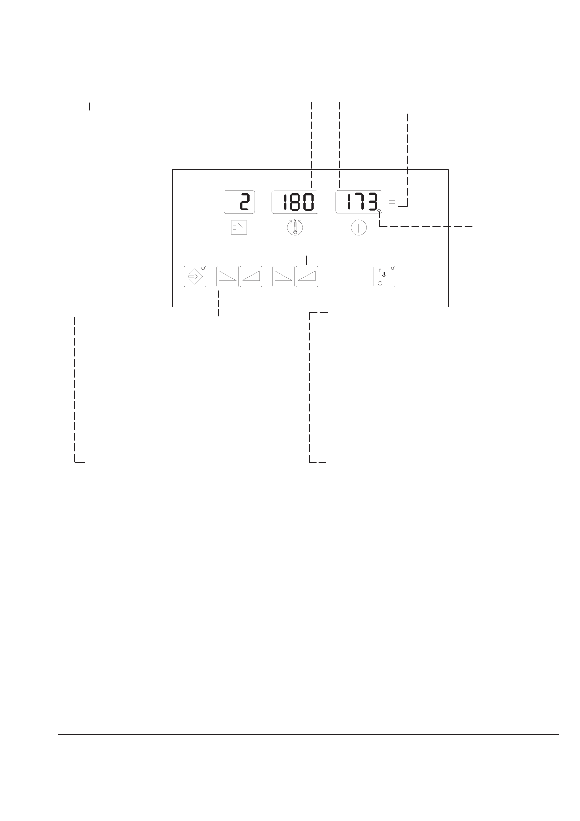
1. Operation Overview
Control system CS 20
11
Displays
Refer to
Program
Overview of Displays
in technical appendix.
and
Diagnosis
16
14
C / F status display
3
13
4
1112
5
C
F
Decimal point
Lit when the displayed
channel is heating.
10
MXCO004L050A0295
Switching on/off immediate temperature setback
Switching ON: Press key 10;
LED in the key lights.
Switching OFF: Press key
has expired (if the setback period is longer than 9.99 hours, the
temperature setback is not automatically ended).
Note: The temperature setback can also be switched on via the
XS 2
interface. When the temperature setback is switched on,
SPL
blinks in displays 4 and 30 (Fig. 1). A setback period is
ineffective in this case.
Note: The
Standstill
part. Press key 25 for approx. 2 seconds.
Automatic T emperature Setback After Motor
is ended by pressing key 25 (Fig. 1) on the motor
SPL
blinks in display 4 and the
10
or wait until the setback period
Press key
display
When the highest channel that is switched on is exceeded,
the following displays/parameters can be called up:
SPL
h SPL
Co OFF
Co On
Lo
Hi
OFF
SE
CF
CLr
If no other key is pressed with 120 sec., these displays
return to the leading channel or the channel with the lowest
number.
13 or 14
3.
Temperature setback value
Temperature setback period
Inert gas interval (option)
Inert gas injection period (option)
Undertemperature value
Overtemperature value
Overtemperature switchoff
Service display (sensor type)
T emperature unit
Return parameter to factory setting
Fig. 5
E 2001 Nordson Corporation
All rights reserved
until the desired channel appears in
CS03
Issued 07/01
Setting temperature setpoint and parametersSwitching channels / selecting parameters
Hold down key 16 and increase value with key 11 or
decrease with key
Pressing once changes the value by 1, holding the
key changes the value faster.
The LED in key
are shown in displays 3, 4 and 5. The following
parameters can be adjusted:
Temperature setpoint
SPL
h SPL
Co OFF
Co On
Lo
Hi
CF
CLr
t1
Temperature setback value
Temperature setback period
Inert gas interval (option)
Inert gas injection period (option)
Undertemperature value
Overtemperature value
T emperature unit
Return parameter to factory setting
(only MC 4420)
12
.
16
is lit when adjustable parameters
P/N 412960D
12
Control system CS 20
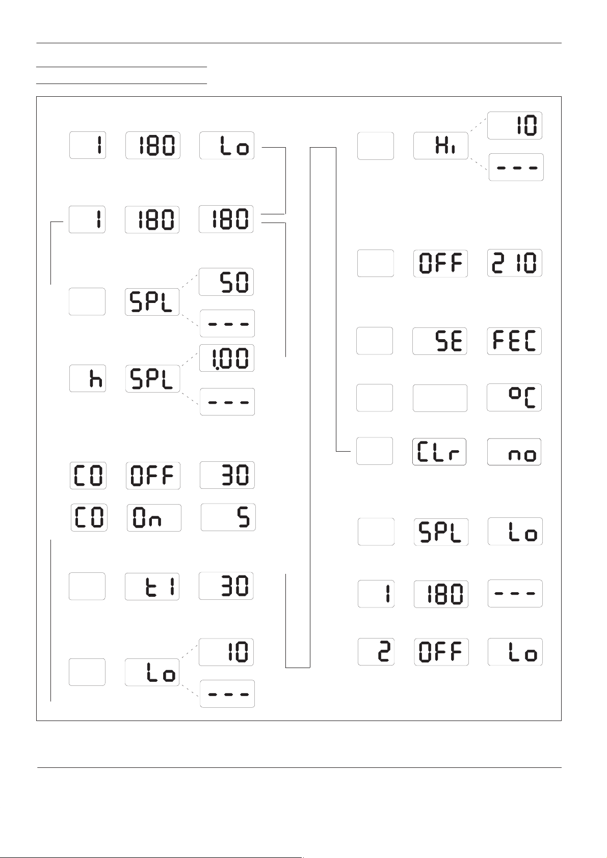
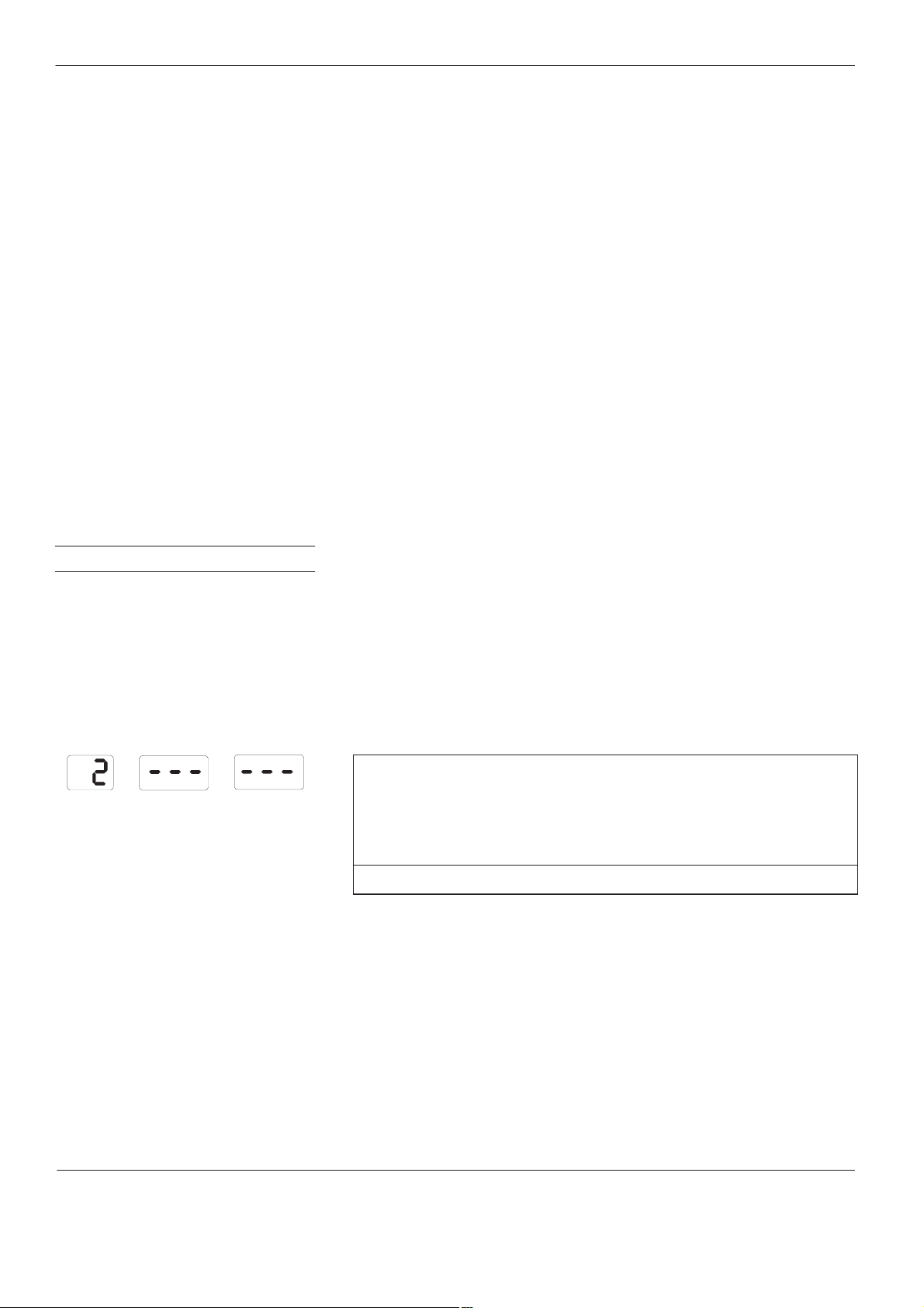
2. Display Overview
Lo / untertemperature (during initial heating phase)
Initial display when unit is switched on.
Channel Temperature setpoint
Normal display
Appears when the channel is heated up.
Channel Temperature setpoint
SPL / temperature setback
Some parameters can be set individually for each channel. Refer to
Setting Parameters by Channel.
Undertemperature
Actual temperature
Setback value
Setback period
B
B
Hi / overtemperature value
B
OFF / overtemperature shutdown
The overtemperature shutdown value is set
automatically 30 °C (54 °F) higher than the highest
temperature setpoint value.
SE / service display (sensor type)
The type of temperature sensor used can be
determined via the service display.
Fe-CuNi
9.99 hours exceeded
CO / inert gas control (option)
For MX units
Interval
Values can be adjusted in these displays (through parameter Hi)
Injection period
Control mode
Only for MC 4420, channel 11 and 12
Time
Lo / undertemperature value
B
Temperature unit (°C / °F)
Return parameter to factory setting
Operating mode displays
Appear automatically.
When the highest active channel is exceeded, these
displays can be called up in this order.
Temperature setback on
Also refer to
setback on/off.
Switching immediate temperature
B
Unit
release not switched
Heaters and motors are switched off
Startup control with leading channel is active.
Fig. 6
P/N 412960D
CS03
Issued 07/01
E 2001 Nordson Corporation
All rights reserved
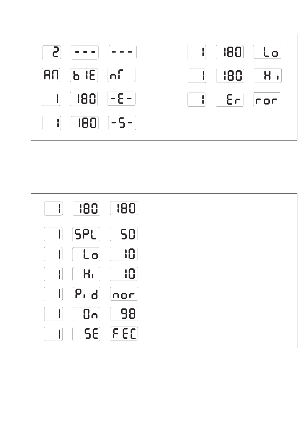
Automatic Fault Displays
Control system CS 20
13
Overtemperature shutdown
Ambient temperature too high
Temperature sensor interruption
Temperature sensor short circuit
Fig. 7
Overview of Parameters Set by
Channel
Normal display
Also refer to
DIP switch
Undertemperature during operation
Overtemperature
Memory error
Diagnosis displays
Not shown here. Refer to
T emperature Part, Diagnosis Program.
T echnical Appendix for
Setting Parameters, Setting Parameters by Channel
S 8
on the temperature control panel board.
and
Display by channel
Fig. 8
PID parameter set
Regulation ratio (only display)
Service display (sensor type)
E 2001 Nordson Corporation
All rights reserved
CS03
Issued 07/01
P/N 412960D
14
Control system CS 20
3. Basic Settings
Startup Control with Leading
Channel
4
3
15 9
5
C
F
8
The startup control with leading channel is only active if a leading
channel has been selected. It prevents hot melt material from charring in
hoses/application heads and the build-up of material expansion pressure
during the initial heating phase. It also helps to save energy.
WARNING: If no leading channel has been selected, the tank
temperature can be set to an unpermissible high value. This
can damage O-rings and the allowable temperature of the unit
surfaces may be exceeded. This warning does not apply to high
temperature units!
Factory setting:
The factory setting depends on the system model.
The channel with the longest initial heating phase
should be chosen as leading channel.
Setting range: See
Technical Appendix of the Temperature Part,
Temperature Control Panel Board, DIP Switch S 8
Depending on the display selected, either C (Celsius) or F (Fahrenheit) of
status display 8 is lit. When display is in Fahrenheit, the control system
continues to use Celsius internally. This may result in up to one degree
Fahrenheit being skipped.
Changing: Use key
until
–P–
blinks in display 5. Change to the other temperature unit using
13
to select display
temperature unit
. Press key
16
key 11 or key 12. Status display 8 changes accordingly.
16
14
13
1112
10
MXCO010S025A0295
Fig. 9 Details from Fig. 1
Switching Scan Mode On/Off
Factory setting:
Degrees Celsius (°C)
In Scan Mode, all activated channels are displayed consecutively at
3 second intervals.
Switching ON: Press keys
Switching OFF: Press key
Factory setting:
13 and 14
13
or 14.
simultaneously .
Scan Mode switched off
P/N 412960D
CS03
Issued 07/01
E 2001 Nordson Corporation
All rights reserved
Control system CS 20
15
Selecting Control or Measuring
Mode
4
3
15 9
16
14
13
Fig. 10 Details from Fig. 1
5
C
F
8
1112
10
MXCO010S025A0295
Switching Channel On/Off
Control mode is the normal function of a channel. The actual temperature
is adapted to the setpoint temperature and kept stable.
In measuring mode, temperature control and monitoring for faults do not
take place. Display 4 is switched off. The measured temperature appears
in display 5. The leading channel cannot be switched into measuring
mode.
Factory setting:
Control mode
Selecting measuring mode: Set temperature setpoint of the channel to
be measured to 40 C (104 F). Press and hold key
16
and press key
12
twice.
Switching back to control mode: Press and hold key
11
twice.
16
and press key
Unused channels are switched off. Switched-off channels are no longer
displayed. The leading channel can not be switched off. Switching on
unconnected channels causes error message
34.
Switching off: Set temperature setpoint to 40 °C (104 °F). Press and
hold key
Switching ON:
1. Use key
2. Press and hold
channel.
3. Press and hold
to 40 C (104 F) or higher.
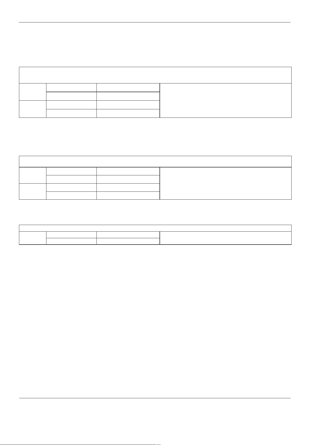
Display examples
Channel T emperature setpoint Actual temperature
16
and press key 12 once.
13
or 14 to select the last switched-on channel.
key 16
key 16
and use key 13 or 14 to select the switched-off
and use key
11
to set the temperature setpoint
Status
D Channel switched on and
D Channel in control mode and
D Channel activated
D Channel switched on and
D Channel in measuring mode and
D Channel activated
D Channel switched on and
D Channel not activated
Unit release
or
not switched
D Channel switched off and
D Channel not activated
This means that the channels that are
switched off are not displayed in the menu
E 2001 Nordson Corporation
All rights reserved
CS03
Issued 07/01
P/N 412960D
16
Control system CS 20
4. Switching Immediate
Temperature Setback
On/Off
5. Setting Temperature
The temperature setback serves to protect the hot melt material and to
save energy during breaks in production. The setback temperature and
setback period can be set (refer to
and
h SPL
).
Parameter Overview
, Parameters
SPL
The temperature setback is switched on and off by the operator. (Refer to
Switching On/Off Automatic Temperature Setback
Switching ON: Press key
10; SPL
blinks in display 4 and the LED in the
in the motor part)
key lights.
Switching OFF: Press key 10 or wait until the setback period has
expired (if the setback period is longer than 9.99 hours, the temperature
setback is not automatically ended).
The temperature setback can also be switched on via the
When the temperature setback is switched on,
SPL
XS 2
interface.
blinks in displays
4
and 30 (Fig. 1). A setback period is ineffective in this case.
WARNING: When setting the temperature, the temperature
prescribed by the material manufacturer is decisive. The
maximum operating temperatures of the unit and of heated
system components may not be exceeded.
4
3
15 9
16
14
13
1112
Fig. 11 Details from Fig. 1
5
C
F
8
10
MXCO010S025A0295
Nordson will not assume any guarantee or liability for damage caused by
incorrect temperature settings.
1. Selecting channel: Press key
16
2. Press and hold key
(in display 4,
13
or 14.
–P–
blinks) and use key 11 to
increase value or key 12 to decrease value.
Pressing once changes the value by 1, holding the key changes the
value faster.
Factory setting: Depends on unit
Setting range: Refer to manual
unit/system
, section
Specifications
P/N 412960D
CS03
Issued 07/01
E 2001 Nordson Corporation
All rights reserved

Control system CS 20
17
6. Setting Parameters
Setback
value
Setting Parameters by Channel
1. Press key 13 or
14
until the desired parameters appear in displays
3
and/or 4.
2. Press and hold key 16 (in display 5,
–P–
blinks) and use key 11 to
increase value or key 12 to decrease value.
Pressing once changes the value by 1, holding the key changes the
value faster.
With the parameters
SPL, Hi
and Lo, all of which can be set individually
for each channel, three lines appear in the display when at least one
channel has a setting that differs from the others. A setting that applies to
all channels is usually sufficient.
Refer to DIP switch
S 8
on the temperature control panel board.
Example of Selecting Parameter Set
1. Press and hold keys
blinks.
2. Press key
13 or 14
Channels that are switched off are automatically skipped.
11
und 12, then press key16 until the display
until the desired channel is displayed.
Return Parameter to Factory
Setting
3. Press key
4. Select parameter set (Refer to previous section,
5. Press and hold keys
11 or 12
until
Pid
is displayed.
11
and 12, then press key
Setting Parameters
16
at the same time to
leave the menu.
If no keys are pressed for approx. 2 minutes, the program automatically
returns to the normal display.
1. Press key
2. Press and hold key 16 (in display 5,
value from
13
or 14 until parameter
no
to
yes
, using key 11 or 12.
CLr
appears in display
–P–
blinks) and set displayed
4.
3. Release all keys. The temperature parameters (with the exception of
temperature setpoint values) will be reset to factory settings.
The value will be
no
again after resetting.
)
E 2001 Nordson Corporation
All rights reserved
CS03
Issued 07/01
P/N 412960D
18
setback tem erature can also be entered by channel (Also refer to
set oint. The setting range for the arameter SPL in then
inert gas equi ment). Refer to
Technical A endix of the Tem era-
MC
The inert gas equi ment described in the motor art is used
Control system CS 20
Parameter Overview
SPL = Setback Temperature
h SPL = Setback Period
The temperature setback serves to protect the hot melt material and to save energy during breaks in production. After the setback period has
expired, the heating is automatically switched back on, but not automatically if the setback period has been set to higher than 9.99 hours. After
9.99 hours, three dashes appear in display
SPL
h SPL
Factory setting:
Setting range:
Factory setting: – – – (off)
Setting range: 0.05 to 9.99 hours
5
(Fig. 1).
50 °C
5 °C to 100 °C (9 °F to 180 °C)
Note: The temperature setback period affects all channels. The
Display Overview, Setting Parameters by Channel
The temperature can not be lowered below the lowest temperature
p
automatically limited.
p
).
p
Co OFF = Inert Gas Interval
Co On = Inert Gas Injection Period
The inert gas control serves to switch on/off the solenoid valve of the optional inert gas equipment. Injection period and interval (time between
two injections) can be set.
CO OFF
CO On
Factory setting: 30 minutes Note: Special function may be activated (only together with optional
Setting range: 2 to 120 minutes
Factory setting: 5 seconds
Setting range: 2 to 120 seconds
ture Part, T emperature Control Panel Board, DIP-Switch S 8.
This additional function must be deactivated for units in the series
...
with these units (parameters
p
p
CoF
and
Con
pp
p
p
)
-
t1 = Control Mode
Time in which the temperature channels 11 and 12 are in control mode. When this time has expired, the channels are automatically deactivated.
t1
Factory setting: 30 minutes Note: Only for MC 4420, channel 11 and 12.
Setting range:
1 to 180 minutes
P/N 412960D
CS03
Issued 07/01
E 2001 Nordson Corporation
All rights reserved
Control system CS 20
(
)
(Also refer to
Dis lay Overview, Setting Parameters by Channel
).
(
)
(Also refer to
Dis lay Overview, Setting Parameters by Channel
).
Lo = Undertemperature Value/Interlock
The undertemperature locking device prevents the unit or system from being started up when the application material is too cold until the
temperature setpoint minus undertemperature value has been exceeded. On every initial heating, however, the locking device is not released
until the actual temperature is 3 °C (5.4 °F) below the temperature setpoint .
The undertemperature locking device blocks the motors, and possibly other components of the application system. Refer to the Wiring Diagram
for an indication of which components are blocked.
Lo
Factory setting:
Setting range:
10 °C
5 °C to 30 °C (9 °F to 54 °C)
Note: The undertemperature value can also be entered by channel
Also refer to
Note for MC 4420:The alarm is deactivated for channels 11 and 12.
Display Overview, Setting Parameters by Channel
.
Hi = Overtemperature Value
19
When the temperature setpoint plus overtemperature value has been reached, the relay output
lamp
Collective fault
Hi
lights. The unit remains ready for operation.
Factory setting:
Setting range:
10 °C
5 °C to 30 °C (9 °F to 54 °C)
Note: The overtemperature value can also be entered by channel
Also refer to
Note for MC 4420: The alarm is deactivated for channels 11 and 12.
Collective fault
Display Overview, Setting Parameters by Channel
is switched and the red indication
OFF = Overtemperature Shutdown
When the overtemperature shutdown reacts (refer to
displays
), there is a unit fault. Switch off the unit and have the fault
eliminated by qualified personnel.
Automatic fault
Pid = Predefined Control Parameters
WARNING: The PID controller may be adjusted only by
personnel trained especially in control technology.
The control parameters (parameter sets SLO, nor, FA1, FA2) can only be set by channel. Refer to DIP switch S 8 on the temperature control
panel board.
Pid
Factory setting: nor SLO: Slow controlled system
nor: Normal controlled system
Setting range: SLO, nor, FA1, FA2
FA1: Fast controlled system
FA2: Fast controlled system
.
E 2001 Nordson Corporation
All rights reserved
CS03
Issued 07/01
P/N 412960D
20
Control system CS 20
On = Regulation Ratio (Display)
The regulation ratio determines the percentage of an interval during
which the heater output is switched on.
Range of values: 0 to 100 %
100 % means that the heater output is always on.
SE = Service Display
The user can find out the type of temperature sensor used for
temperature module 1 via the service display
Setting by Channel
:
SE;
for each channel under
S FEC = Fe-CuNi
S Pt = Pt 100
S ni = Ni 120.
7. Automatic Fault Displays
If multiple faults are present, the channel with the lowest channel number
and the fault with the highest priority are displayed.
The number of a faulty channel appears in the left display; the fault
indication is shown in the middle and right displays.
Overtemperature shutdown
The shutdown depends on the setting of the DIP switch
temperature control panel board (Refer to
Temperature Part
Activation
Deactivation Switch on/off unit
).
When the overtemperature shutdown value is
reached
or
Shutdown temperature was exceeded for more
than 120 seconds / temperature increased
Technical Appendix for
S 8.8
on the
P/N 412960D
CS03
Issued 07/01
E 2001 Nordson Corporation
All rights reserved

Ambient temperature too high
Control system CS 20
21
Activation
Electrical cabinet internal temperature is higher
than 60 °C (140 °F) for more than 120 seconds
Deactivation Switch on/off unit
T emperature sensor interruption
Activation Interruption for more than 5 seconds
Deactivation Eliminate fault
Temperature sensor short-circuit (not for Fe-CuNi sensors)
Activation Short-circuit for more than 5 seconds
Deactivation Eliminate fault
Undertemperature during operation
Activation
Actual temperature goes below temperature
setpoint minus undertemperature value for more
than 10 seconds
Automatic
deactivation
Actual temperature exceeds temperature
setpoint minus 3 °C (5.4 °F) for more than
5 seconds
Overtemperature
Activation Actual temperature exceeds temperature
setpoint plus overtemperature value for more
than 10 seconds
Automatic
deactivation
Actual temperature goes below temperature
setpoint plus 3 °C (5.4 °F) for more than
5 seconds
Memory error
Activation The memory of the displayed temperature
channel is probably defective. Replace
corresponding module if this occurs again.
Deactivation Switch on/off unit
E 2001 Nordson Corporation
All rights reserved
CS03
Issued 07/01
P/N 412960D

22
Control system CS 20
8. Bar Graph (Option)
1234
Fig. 12
1. Red (3rd deviation upward)
2. Yellow (2nd deviation upward)
3. Yellow (1st deviation upward)
The bar graph indicates in which range the temperature is currently
located for all activated channels.
The sensitivity and deviation value (at which temperature deviation the
next LED lights) can be set on a DIP switch. The DIP switch
located on the bar graph board (see
Temperature Part, Bar Graph
). The setting affects all bar displays.
Technical Appendix of the
S 3
is
Channels 1 to 12
5
4. Green (no deviation)
5. Yellow (1st deviation downward)
6 7 8 9 10 11 12
6. Yellow (2nd deviation downward)
7. Red (3rd deviation downward)
red
1
yellow
2
yellow
3
green
4
5
yellow
6
yellow
7
red
MXCO038L050A0595
P/N 412960D
CS03
Issued 07/01
E 2001 Nordson Corporation
All rights reserved

Operating the Motor Part
Operation by electrostatically-charged persons can lead to improper
functioning of the control system.
Control system CS 20
WARNING: Allow only qualified personnel to perform the
following tasks. Observe and follow the safety instructions in
this document and all other related documentation.
23
Alteration of values and parameters can be blocked (see
Technical
Appendix of the Motor Part, Central Module, DIP Switch S 6
).
E 2001 Nordson Corporation
All rights reserved
CS03
Issued 07/01
P/N 412960D

24
Control system CS 20
1. Operation Overview
Switch on motor
First press key 27 on the appropriate motor panel (motor is pre-selected, LED in key 27 is lit).
Then press key
Switch off one motor
Press only key
Switch off all motors
Press only key
Switch off automatic temperature setback
Press only key
25
(motor is switched on, LED in key
27
on the corresponding motor panel.
25
.
25
for approx. 2 seconds.
25
and illuminated symbol 29 are lit).
3027 31
29
26
min
Displays
Refer to
–1
Display Overview
bar
psi
and
Service Display.
25
23
Setting speed (manual mode)
Press key 27 for approx. 2 seconds (until –P–
blinks in display 30). Then increase value with
key
22
or decrease with key 23.
Pressing once changes the value by 1, holding
the key changes the value faster.
Setting speed (automatic mode)
In automatic mode the motor/pump speed is
regulated synchronously to the speed of the
parent machine. Adjustment directly affects
the parameter
and
Parameter Overview
rhi
(Refer to
Display Overview
).
Set values and parameters
Refer to
1. Press and hold keys
2 seconds. Displays 30
2. Press key
display
3. Press and hold key 27 (in display 31, –P– blinks) and use key
22
Complete:
Press and hold keys
2 seconds.
Display Overview
22 or 23
30.
to increase value or key 23 to decrease value.
and the detailed description.
22 and 23 and press key 27 for approx.
and 31 blink.
until the desired parameter appears in
22
and
23
and press key 27 for approx.
22
21 20
Select manual or automatic mode
Press key 27 for approx. 2 seconds (until in display
30
or automatic mode. In manual mode, symbol
lights.
MXCO005L050A0295
Test
27
Press and hold key
display 30. Then press 20 for the duration of
the test
WARNING: Risk of burns. Hot melt material
can flow out of the application head.
In test mode, the motor runs (in manual mode
at the set speed, in automatic mode at speed
rhi
). Other components may also be
triggered. Refer to the wiring diagram to see
which components are controlled.
until –P– blinks in
T est displays and indicator beacon
(option)
Press key 20.
, –P– blinks). Then use key 21 to select manual
26
Fig. 13
P/N 412960D
CS03
Issued 07/01
E 2001 Nordson Corporation
All rights reserved

2. Display Overview
Control system CS 20
25
Normal display
Speed min
NOTE: When the pressure display
shows psi, multiply the value by 10.
-1
Pressure (option)
Parameters and values
Options and special functions
are displayed only when they
are available in the system. Also
refer to
Parameter Overview
Speed setpoint (manual mode)
Motor speed at 0 % pilot voltage
Works only in automatic mode, additional function that can be activated
Motor speed at pilot voltage
Functions only in automatic mode
.
Uhi
"
Threshold value switch (option)
Reverse mode (option)
Speed adaptated to special
gear box (additional function
that can be activated)
Speed alarm (special function
that can be activated)
Only MC units
Operating mode displays
Appear automatically .
Temperature setback active
Also refer to
Unit
release not switched
Parameter Overview
.
Automatic Fault Displays
Speed alarm
(special function that can be activated)
Also refer to
Coupling fault (special function)
Also refer to Digital Module, Function
of Input Signal.
Overpressure alarm (special function)
Also refer to
Parameter Overview
Parameter Overview
.
.
Pilot voltage in % at which the
motor rotates at speed
Works only in automatic mode, additional function that can be activated
Period after motor standstill at
which the temperature setback
is automatically switched on.
Switching pressure display
between
Variable pressure measuring range
1 to 680 bar (special function)
Underpressure alarm (special function)
bar
/
psi
rhi
.
"
Overpressure alarm (special function)
Continuation of parameters and values
Inert gas control (injection period)
Inert gas control (interval)
Forcibly actuated inert gas injection
Forcibly actuated air exhaust
(vacuum pump)
Return values to factory setting
Field bus address of unit
(only with PROFIBUS DP)
Underpressure alarm (special function)
Also refer to
Safety valve opened (special function)
The safety valve opens upon occurrence
of overpressure (error number 243). Also
refer to
inputs and outputs.
Error display
The error number appears in the right
display. Refer to
for more details.
Parameter Overview
Digital Module
Service Display Error
.
, description of
Double stream pumps
Second pressure display
Service displays
Refer to
Service Display.
Fig. 14
E 2001 Nordson Corporation
All rights reserved
CS03
Issued 07/01
P/N 412960D

26
Control system CS 20
2. Display Overview
Parameters and values when
pressure is controlled
The functions
Speed alarm
value switch
drives in pressure control mode.
Pressure at 0% pilot voltage
(automatic mode)
Pressure at pilot voltage
(automatic mode)
Pressure setpoint (manual mode)
Reverse mode,
and
Threshold
are not valid for
Uhi
(contd.)
Overpressure value (corresponds
to
Phi
for speed control)
Underpressure value
(corresponds to
control)
Plo
for speed
Mode display
(instead of speed display)
Pressure control active
P/N 412960D
CS03
Issued 07/01
E 2001 Nordson Corporation
All rights reserved

Control system CS 20
27
3. Pressure Control
When this function is activated (Refer to digital module, selector switch
S 1, setting A, inputs), the selected drives are switched from speed
control to pressure control. Instead of a speed, a pressure setpoint is
determined. The setpoint can be entered as a value (manual mode) or
set via pilot voltage (automatic mode). The speed required to reach the
pressure is calculated internally by the control system.
The parameters
PSL, PSH, PSP, PAH, PAL
and the display
Pcr
are
available for pressure control. For a description of the parameters, refer
to
Display Overview, Parameters and Values for Pressure Control
and
Parameter Overview, Special Function Pressure Control
All entries are made in bar, even when the pressure display is set to psi.
There is a common relay output for underpressure alarm and a common
relay output for overpressure alarm for all (maximum of six) drives.
The pressure sensor measuring range can be modified with the
parameter
PRS
or with the selector switch on the analog module. If the
pressure parameter values are no longer within the permissible
(measuring) range after modification, the parameters are returned to the
factory setting.
The same relay output is used for the function
Pressure Control. Pressure control
takes precedence over
Reverse
as for the function
Reverse
.
E 2001 Nordson Corporation
All rights reserved
CS03
Issued 07/01
P/N 412960D

28
(
Control system CS 20
4. Basic Settings
Selecting Manual or Automatic
Mode
Selecting Pressure Display
Option) bar or psi
Manual mode: The setpoint is equal to the set value and remains stable.
Automatic mode: The speed is controlled by pilot voltage. The
parameters
Automatic mode is only possible if pilot voltage is available.
1. Press key 27 for approx. 2 seconds (in display 30,
2. Press key
mode, symbol
Special function: Manual mode supersedes automatic mode; this
means:
If manual mode was activated on the control panel, the digital module
can not be used to switch to automatic mode.
If the digital module was used to switch to manual mode, automatic mode
can not be activated on the control panel.
Pressure can be displayed in bar or psi. For display in psi, the right
decimal point in display
For display in psi, multiply the value by 10.
rLo, rHi
or
PSL, PSH
21
until the desired operating mode appears. In manual
26
lights
31
.
lights.
and
Uhi
can be set.
–P–
blinks).
22
1. Press and hold keys
seconds. Displays 30 and 31 blink.
2. Press key
3. Press and hold key
to set
4. End
key
bar
PSI
22 or 23
YES
(psi) or no (bar).
Selecting bar or psi:
27
for approx. 2 seconds.
Factory setting: bar
Setting range: YES / psi or no / bar
and 23 and press key 27 for approx. 2
until display 31 shows
27
for approx. 2 seconds, then use key 22 or 23
Press and hold keys 22 and 23 and press
PSi
.
P/N 412960D
CS03
Issued 07/01
E 2001 Nordson Corporation
All rights reserved

Control system CS 20
29
5. Test
29
26
30 31
min
23
22 21 20
–1
bar
psi
MXCO009S0270295
28
M1
27
24
25
Fig. 15 Details from Fig. 1
6. Switching ON Motor(s)
WARNING: Risk of burns. Hot melt material can flow out of the
application head (accessory).
In test mode, the motor runs (in manual mode at the set speed, in
automatic mode at speed
rhi
). Other components of the application
system may also be controlled. Refer to the wiring diagram to see which
components are controlled.
1. Press and hold key
27
until –P– blinks in display 30. Then press
20
for the duration of the test
Motors can only be switched on when the green indication lamp
Ready
(19, Fig. 1 and 4) is lit.
In automatic mode, the operating characteristic of the motor is
determined by parameters
With the option
Threshold value switch
dependant on the parameter settings
rLo, rhi
and
Uhi
.
, the motor is started and stopped
Slo
and
Shi
.
Motor Startup Protection
The motor can also be switched on/off externally through an interface.
27
1. Pre-select the motor(s): Press key
(pre-selected motor is indicated
by LED 28).
2. Switch on motor(s): Press key 25 (switched-on motors are indicated
by LED 24 and illuminated symbol 29).
The motor startup protection prevents the motors from starting up after
the initial heating phase or after a system error. When the startup
protection is activated, LED 24 in key 25 blinks.
To switch the motors back on: Press key 25 or, with external control via
interface, activate the input
Release all motors
once.
E 2001 Nordson Corporation
All rights reserved
CS03
Issued 07/01
P/N 412960D
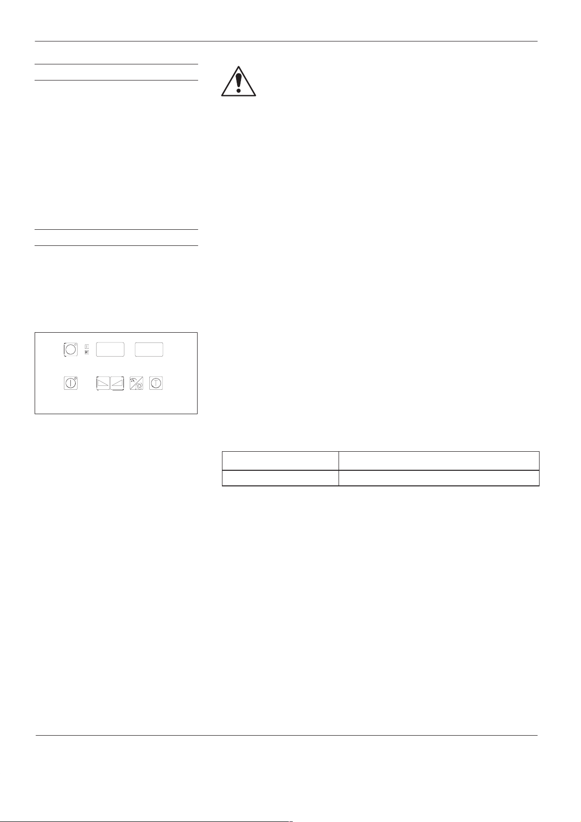
30
)
Control system CS 20
7. Switching OFF Motor(s)
Switch Off one Motor
Switch Off all Motors
8. Set Speed (Manual Mode
29
26
30 31
min
23
22 21 20
–1
bar
psi
MXCO009S0270295
28
M1
27
24
25
WARNING: On units with the option
Reverse mode
, the motor
rotates in reverse after being switched off (for the set time at the
set speed).
Press key 27 of the corresponding motor panel. The LED
preselected
Press key 25. The LED
turns off.
Motor(s) on
turns off.
Motor
To prevent excessive wear, the motor/pump speed should not
continuously fall below 5 min-
1
(rpm) or continuously exceed 80 min
(rpm).
The speed setpoint can be adjusted in steps of 0.1. The actual speed
display is shown in steps of 1.0.
Changing speed directly:
1. Press key
for approx. 2 seconds (until in display 30,
–P–
blinks).
27
2. Increase value with key 22 or decrease with key 23.
The speed setpoint can also be changed in the menu (parameter
proceed as described under
Setting parameters
.
rSP
-1
);
Fig. 16 Details from Fig. 1
Factory setting: 5.0 min
Setting range:
1.0 to 100 min
-1
Ć1
P/N 412960D
CS03
Issued 07/01
E 2001 Nordson Corporation
All rights reserved

Control system CS 20
c
31
9. Setting Speed (Automati
Mode)
29
26
30 31
min
23
22 21 20
–1
bar
psi
MXCO009S0270295
28
M1
27
24
25
Fig. 17 Details from Fig. 1
To prevent excessive wear, the motor/pump speed should not
continuously fall below 5 min-1 (rpm) or continuously exceed 80 min
(rpm).
rhi
Changing
1. Press key 27 for approx. 2 seconds (until
and
directly:
rhi
blinks in display 31).
–P–
blinks in display
2. Increase value with key 22 or decrease with key 23.
rhi
increases (decreases) as soon as the motor speed is increased
(decreased). The motor speed can be increased until
rhi
=100 min
Ć1
(rpm).
rhi
can also be changed in the menu; then proceed as described under
Setting Parameters
Factory setting (rhi): 80 min
Setting range (rhi):
.
-1
1.0 to 100 min
Ć1
-1
30
Speed Parameters in Automatic
Mode
Via interface XS 5 (without Profibus)
The parameters
Parameter Overview
1. Select
Mode
).
2. Set parameters:
rhi
Refer to
refer to
rLo
Refer to
Uhi
Refer to
3. Determine pilot voltage via interface
rLo, rhi
and
Uhi
function in automatic mode (Refer to
).
automatic mode
(Refer to
Setting Speed (Automatic Mode)
Setting Parameters
Setting Parameters
Setting Parameters
Selecting Manual or Automatic
XS 5
.
Via interface XS 5 (with Profibus)
1. Select automatic mode (index 72, bit 1=1)
Select pilot voltage via interface XS (analog signal)
2.
(index 60, bit 10=1)
3. Set parameters:
Limit maximum pump speed
Set
Set
Limit minimum pump speed
Set
Limit pilot voltage/machine speed
(Index 78)
(index 79)
(index 80)
- direct change or
E 2001 Nordson Corporation
All rights reserved
4. Determine pilot voltage via interface
CS03
Issued 07/01
XS 5
.
P/N 412960D

32
Control system CS 20
Speed Parameters in
Automatic Mode
(contd.)
Via Profibus
1. Select automatic mode (index 72, bit 1=1)
2.
Select machine speed via field bus (digital signal)
(index 60, bit 10=0)
3. Set parameters:
Set
Limit maximum pump speed
Set
Limit minimum pump speed
Set
Limit pilot voltage/machine speed
(Index 78)
4. Determine
Pilot voltage/machine speed (automatic mode)
(index 79)
(index 80)
(Index 82).
P/N 412960D
CS03
Issued 07/01
E 2001 Nordson Corporation
All rights reserved

Control system CS 20
33
10. Switching Automatic
Temperature Setback
ON/OFF
11. Setting Parameters
The purpose of the temperature setback is to protect the material and to
save energy during breaks (Refer to
SPL
).
SPL
is the motor standstill time after which the temperature setback is
automatically switched back on. (Refer to
Setback
Switching ON:
15 minutes (factory setting is OFF).
Switching OFF: The
Standstill
2 seconds.
1. Press and hold keys 22 and
2. Press key
3. Press and hold key 27 (in display 31,
in the temperature part.)
SPL
must be set to a value equal to or greater than
Automatic Temperature Setback After Motor
is ended by pressing key 25 (Fig. 1). Press key 25 for approx.
2 seconds. Displays 30 and 31 blink.
22 or 23
increase value or key 23 to decrease value.
Pressing once changes the value by 1, holding the key changes the
value faster.
until the desired parameter appears in display
Parameter Overview
Immediate Temperature
23
and press key 27 for approx.
–P–
blinks) and use key 22 to
, parameter
30.
Return Parameter to Factory
Setting
4. End
1. Press and hold keys 22 and
2. Press key
3. Press and hold key
4. Press key
5. Release key 27 (after approx. 2 seconds display 31 shows no). All
6. End
Setting parameters
key 27 for approx. 2 seconds.
seconds. Displays 30 and 31 blink.
22 or 23
no
.
22
or 23 until display 31 shows
settings have now been returned to factory settings.
Returning parameters to factory settings
and
23
and press key 27 for approx. 2 seconds.
: Press and hold keys 22 and
23
and press key 27 for approx. 2
until display 30 shows
27
(in display 31,
–P–
CLr
and display 31 shows
and no blink).
YES
.
: Press and hold keys
23
and press
22
E 2001 Nordson Corporation
All rights reserved
CS03
Issued 07/01
P/N 412960D

34
central module
tral module
Control system CS 20
Parameter Overview
See rLo, rhi and Uhi, graphic illustration
rLo
See rLo, rhi and Uhi, graphic illustration
rhi
Factory setting: 1.0 min
Setting range: 1.0 to 100 min
Setting increments: 0.1 steps
Factory setting: 80 min
Setting range: 1.0 to 100 min
Setting increments: 0.1 steps
Also refer to
Setting parameters
.
rLo = Motor Speed at 0 % Pilot Voltage
-1
-1
Note: Functions only in automatic mode
Note: Special function may be activated. DIP switch S 6 on the
rhi = Motor Speed at Pilot Voltage Uhi
-1
-1
Note: Functions only in automatic mode
Uhi = Pilot Voltage at which the Motor Rotates Constantly at
rhi
Pilot voltage at which the motor rotates at speed rhi. If the pilot voltage exceeds
graphic illustration
Uhi
Factory setting: 100 % pilot voltage Note: Functions only in automatic mode
Setting range: 0 to 100 % pilot voltage
Note: Special function may be activated. DIP switch S 6 on the cen-
Setting increments: 0.1 steps
rLo, rhi and Uhi, Graphic Illustration
rLo = 1 min-1 / rhi = 75 min-1 / Uhi = 100 %
100
80
60
40
20
Motor speed in min-1
0
20 40 60 80 100
0
Pilot voltage in %
Fig. 18 Motor speed to pilot voltage – Examples –
rLo = 25 min-1 / rhi = 100 min-1 / Uhi = 100 %
100
80
60
40
20
Motor speed in min-1
0
20 40 60 80 100
0
Pilot voltage in %
rLo = 20 min-1 / rhi = 70 min-1 / Uhi = 100 %
Motor speed in min-1
See also Central Module, DIP-Switch S 6, Switch 4
Uhi
, the speed remains constant at
100
80
60
40
20
0
20 40 60 80 100
0
Pilot voltage in %
rhi
. See rLo, rhi and Uhi,
rLo = 1 min-1 / rhi = 90 min-1 / Uhi = 60 %
100
80
60
40
20
Motor speed in min-1
0
20 40 60 80 100
0
Pilot voltage in %
P/N 412960D
CS03
Issued 07/01
E 2001 Nordson Corporation
All rights reserved

See PSL, PSH and Uhi graphic illustration
,
If an attem t is made to set the value PSH to less than PSL, the value PSL
g
If an attem t is made to set the value PSL to higher than PSH, the value
PSH
Factory setting: 10 % of pressure measuring
Setting range: 0.1 bar to 70 % of pressure
Setting increments: Up to 100 bar: 0.1 steps
Siehe PSL, PSH and Uhi graphic illustration
PSL
Factory setting: 1 % of pressure measuring
Setting range: 0.1 bar to 70 % of pressure
Setting increments: Up to 100 bar: 0.1 steps
range upper limit
measuring range upper limit
Over 100 bar: steps of 1
range upper limit
measuring range upper limit
Over 100 bar: steps of 1
Control system CS 20
Special Function Pressure Control:
PSH = Pressure at Pilot Voltage Uhi
Note: Corresponds to rhi when speed controlled.
If an attempt is made to set the value PSH to less than PSL
is automatically reduced.
PSL = Pressure at 0 % Pilot Voltage
Note: Corresponds to rLo when speed controlled
If an attempt is made to set the value PSL to hi
PSH is automatically increased.
35
the value PSL
her than PSH, the value
PSP = Pressure Setpoint (Manual Mode)
The function
longer shown.
PSP
Pressure control
can be deactivated (OFF) for individual drives with this parameter. The other pressure control parameters are no
Factory setting: OFF Note: Corresponds to speed setpoint in manual mode when speed
Setting range: OFF or 0.1 bar to 70 % of
controlled.
pressure measuring range
upper limit
Setting increments: Up to 100 bar: 0.1 steps
Over 100 bar: steps of 1
PSL, PSH and Uhi, Graphic Illustration
PSL = 1 bar / PSH = 70 bar / Uhi = 100 %
100
80
60
40
Pressure in bar
20
0
20 40 60 80 100
0
Pilot voltage in %
Fig. 19 Pressure to pilot voltage – example of a 100 bar pressure sensor –
PSL = 25 bar / PSH = 70 bar / Uhi = 100 %
100
80
60
40
Pressure in bar
20
0
20 40 60 80 100
0
Pilot voltage in %
PSL = 20 bar / PSH = 30 bar / Uhi = 100 %
100
80
60
40
Pressure in bar
20
0
20 40 60 80 100
0
Pilot voltage in %
PSL = 1 bar / PSH = 70 bar / Uhi = 60 %
100
80
60
40
Pressure in bar
20
0
0
20 40 60 80 100
Pilot voltage in %
E 2001 Nordson Corporation
All rights reserved
CS03
Issued 07/01
P/N 412960D

36
SPL i
N
PrS
function for this ressure sensor is deactivated
Control system CS 20
Parameter Overview
(contd.)
PAH = Pressure Monitoring for Overpressure (when Pressure
Controlled)
PAL = Pressure Monitoring for Underpressure (when Pressure
Controlled)
Overpressure and underpressure values are differential values.
Pressure monitoring serves to indicate underpressure or overpressure and, if necessary, to stop all motors on overpressure.
PAL = Underpressure: If the pressure value falls below the alarm limit (setpoint minus underpressure value) for more than 10 seconds, PAL
appears in display 30 (Fig. 1), and the red indication lamp
setpoint = 2 bar, PAL = 3 bar), no underpressure alarm can be triggered (Refer to example).
PAH = Overpressure: If the pressure value exceeds the alarm limit (setpoint plus overpressure value) for more than 20 seconds, PAH appears
in display 30 (Fig. 1), and the red indication lamp
60 seconds, the motors are all stopped and the green indication lamp
Underpressure and overpressure monitoring can each be deactivated for individual motors by setting the parameter to less than 2 % (display
OFF). The relay outlets indicate
The error indications PAL and PAH can be reset by switching the motors on/off. It is then possible to see which motor set off the pressure alarm.
PAL
Factory setting: OFF Note: Special function
PAH
Setting range: OFF or 2.0 % to 30 % of
Setting increments: Up to 100 bar: 0.1 steps
No underpressure
pressure measuring range
upper limit
Over 100 bar: steps of 1
Collective fault
Collective fault
or
No overpressure
lights up (error number 242). If the alarm limit is below 0 bar (e.g.
lights up (error number 241). If the alarm limit is exceeded for more than
Ready for operation
.
Note: PAH corresponds to Phi, and PAL corresponds to Plo when speed
controlled.
Example:
goes off (error number 240).
p [bar]
100 %
2
0
100 System pressure [%]
PAH
PAL
3 bar
SPL = Temperature Setback after Motor Standstill
SPL is the time after which the automatic temperature setback after motor standstill begins. The temperature is then decreased to the value of
parameter SPL (setback temperature) set in the temperature part.
SPL
Factory setting: OFF Note: The function
Setting range: 15 to 240 minutes
Setting increments: Steps of 1
s within the setting range.
ote: End temperature setback: Press key 25 for approx. 2 seconds.
T emperature setback
is only switched on if the value of
PdS = Second Display for Double Stream Pumps
When both double and single stream pumps are used, the second pressure display can be switched off with the parameter
display).
The parameter can be called up only in the second line.
SPL
Factory setting: ON Note: If the pressure display is switched off, the parameters
Setting range: ON or OFF
Setting increments: Steps of 1
are not shown in the control panel line; also, the pressure monitoring
p
PdS
(pressure
Phi, Plo
and
.
P/N 412960D
CS03
Issued 07/01
E 2001 Nordson Corporation
All rights reserved

Control system CS 20
)
Note: The arameters are only available if the selector switch S 11 of the
Not
XS 2 Interface (s ecial version
refer to Wiring Diagram)
tti
PrS = Variable Pressure Measuring Range
The variable pressure measuring range serves to adjust special pressure sensors to the control system.
PrS
Factory setting: 100 bar Note: Special function; the parameter is only available if the selector switch
Setting range: 1 to 680 bar
Setting increments: Up to 100 bar: 0.1 steps
Over 100 bar: steps of 1
S 1 of the analog module is in position 5 (see
Note: Setting must be carried out for each pressure sensor (in each motor
panel).
Note: When double stream pumps are used, pressure sensors with different
measuring ranges can be used for each pump stream. The parameter
can be set separately for each pressure sensor for this purpose.
Analog Module
Plo = Pressure Monitoring for Underpressure
Phi = Pressure Monitoring for Overpressure
37
)
PrS
The parameters
Pressure monitoring serves to indicate underpressure or overpressure and, if necessary, to stop all motors on overpressure.
PLo = Underpressure: If the pressure goes below the underpressure limiting value for longer than 20 seconds, Plo appears in Display 30 (Fig. 1)
and the red indication lamp
Phi = Overpressure: If the pressure exceeds the overpressure limiting value for longer than 20 seconds, Phi appears in display 30 (Fig. 1) and
the red indication lamp
60 seconds, all motors are stopped and the green indication lamp
The error messages Plo and Phi are deleted by switching the motors off and on. It is then possible to see which motor set off the pressure
alarm.
Plo
Factory setting: OFF Note: Special function together with pressure sensor.
Setting range: OFF or 1 to x bar (x = pressure
Setting increments: Steps of 1
Phi
Factory setting: OFF
Setting range: OFF or 1 to x bar (x = pressure
Setting increments: Steps of 1
Collective fault
Collective fault
sensor measuring range)
sensor measuring range)
lights (error number 242).
lights up (error number 241). If the pressure exceeds the overpressure limiting value for more than
Plo
and
Phi
are omitted when pressure controlled.
Ready for operation
digital module is set to position A (see
).
Output
e: Pressure monitoring is not controlled by pilot voltage. It should only be
switched on at normal production speed. It is switched on/off through the
Note: The measuring range of the pressure sensor (x) corresponds to the
se
ng of the selector switch S1 at the analog module.
Note: When double stream pumps are used, pressure limits can be set for
each pump stream with the parameters
displays
active.
Phi
is extinguished (error number 240).
p
p
and
Plo
appear in the display line in which the pressure alarm is
,
Central Module with Digital Input/
.
Phi
and
Plo
. The automatic fault
E 2001 Nordson Corporation
All rights reserved
CS03
Issued 07/01
P/N 412960D

38
function
Pressure control. Pressure control
takes precedence over
Reverse
Control system CS 20
Parameter Overview
(contd.)
SLo = Threshold Value Switch, Lower Value
Shi = Threshold Value Switch, Upper Value
The threshold value switch serves to start and stop the motor dependent on pilot voltage. The motor starts when the value exceeds Shi and
stops when the value goes below SLo. See graphic illustration of SLo and Shi.
SLo
Factory setting: OFF Note: Option; it is activated at the factory by a software expansion module
Setting range: OFF or 1 to 100 %
Setting increments: 0.1 steps
Shi
Factory setting: OFF
Setting range: OFF or 1 to 100 %
Setting increments: 0.1 steps
of pilot voltage
of pilot voltage
to the central module.
Note: Setting is only possible in motor panel 1.
Note:
Shi
must be higher than SLo.
SLo and Shi, Graphic Illustration
Motor
On
Off
0
ShiSLo
100 %
Pilot voltage
drS = Reverse Speed
drt = Reverse Time
Reverse mode is used for example when the hot melt material is applied through application heads which have no mechanical devices to stop
its flow. By reversing the motor (opposite rotation), the hot melt material is sucked out of the nozzle, preventing the hot melt material from dripping.
On units with the option
(30) blinks during this period. Reverse mode is only switched on when the value drS is within the setting range (the right decimal point in display
30 is lit).
drS
Factory setting: OFF Note: Option; it is activated at the factory by a software expansion module
Setting range: OFF or 1.0 to 100 min
Setting increments: 0.1 steps
drt
Factory setting: 0.5 seconds
Setting range: 0.5 to 25 seconds
Setting increments: Steps of 1
reverse mode
, the motor rotates in reverse after being switched off (if reverse mode is switched on). The speed display
-1
to the central module.
Note: The same relay output is used for the function
p
Reverse
as for the
.
P/N 412960D
CS03
Issued 07/01
E 2001 Nordson Corporation
All rights reserved

Control system CS 20
M
DIP Switch S 2
ldb
rPU = Adapting Speed to Special Gearbox
The parameter rPU serves to adjust the speed display to the max. gearbox output speed of a special gearbox (all other parameters remain unchanged). For example, if the max. gearbox output speed is 60 min-1, the parameter is set so that the speed display shows also 60 min-1.
rPU
Factory setting: 100 min
Setting range: 1.0 to 250 min
Setting increments: 0.1 steps
-1
-1
Note: Special function may be activated. See
otor Part, Motor Panel Board,
T echnical Appendix of the
r_d = Limiting Value for Speed Alarm
The speed alarm serves to indicate any fluctuations in speed and, if necessary, to switch off all motors or even the unit. With speed alarm, the
red indication lamp lights up and r_d appears automatically in display 30. The error can be more exactly determined by activating the
Display Error
Speed alarm is activated by the following fluctuations:
The actual speed deviates from the limiting value r_d for longer than 10 seconds (red indication lamp lights / error number 245). When the ac-
tual speed returns within the range of limiting values, the error message is automatically deleted.
The actual speed exceeds the limiting value r_d by a factor of 3 and longer than 12 seconds (motors are stopped / red indication lamp lights /
error number 246). The speed alarm must be deleted. If the motors were not immediately stopped but rotate for another 6 seconds, the main
contactor drops (unit is switched off / error number 247). The speed alarm must be deleted.
To delete speed alarm: Switch off all motors.
r_d
(error numbers 245, 246 and 247 are possible).
Factory setting: OFF Note: Only on units with actual speed compiler
Setting range: OFF or 2 to 10 min
Setting increments: Steps of 1
-1
Service
39
Adr = Field Bus Address of Unit
Only with option
Adr
Factory setting: 10 Note: Every unit on the PROFIBUS needs a field bus address for
Setting range: 2 to 126
Setting increments: Steps of 1
PROFIBUS DP
communication. Each address may be assigned only once in the fie
us.
E 2001 Nordson Corporation
All rights reserved
CS03
Issued 07/01
P/N 412960D

40
C
OFF
C
) i
MX
Thi
series
MC
that are equi ed with a vacuum um
Control system CS 20
Parameter Overview
(contd.)
Only Units of the Series MC:
CoF = Inert Gas Control (Interval)
Con = Inert Gas Control (Injection Period)
The inert gas control is used to turn on/off the solenoid valve of the inert gas equipment. The injection period and the interval (time between
two inert gas injections) can be set.
CoF
Factory setting: 30 minutes
Setting range: 2 to 120 minutes
Setting increments: Steps of 1
Con
Factory setting: 5 seconds
Setting range: OFF or 2 to 120 seconds
Setting increments: Steps of 1
Note: The parameters and are only in the system if the selector
switch of the central module is set to B.
Note:The inert gas control described in the temperature part (parameters
o
and
o On
s currently used for units of the series
...
C1 = Forcibly Actuated Inert Gas Injection
The forcibly actuated inert gas injection is triggered when the tank hood is closed or when the parameter has ended. Then inert gas
pressurization is applied according to the parameter settings and .
C1
Factory setting: 30 seconds
Setting range: 2 to 240 seconds
Setting increments: Steps of 1
Note: The parameter is only in the system if the selector switch of
the centralmoduleis set toB.
Note:The parameter C1 is reset every time the tank hood is opened.
C2 = Forcibly Actuated Air Exhaust (Vacuum Pump)
The forcibly actuated air exhaust is triggered when the tank hood is closed. Then forcibly actuated inert gas injection (parameter ) occurs,
and then inert gas pressurization is applied according to the parameter settings and .
C2
Factory setting: 60 seconds Note: The parameter C2 is only in the system if the selector switch
Setting range: OFF or 2 to 240 seconds
Setting increments: Steps of 1
the central module is set to B.
...
pp
s parameter is used only with units in the
p
p
.
S 11
of
P/N 412960D
CS03
Issued 07/01
E 2001 Nordson Corporation
All rights reserved

Control system CS 20
41
12. Service Displays
29
26
30 31
min
23
22 21 20
–1
28
M1
27
24
25
Fig. 20 Details from Fig. 1
bar
psi
MXCO009S0270295
General service displays appear only in the display for motor 1;
motor-related displays appear in the display for the motor in question.
The service displays can be activated as follows:
1. DIP switch
factory setting (switches 1 and 2 in position
S 6
on the central module must be at or switched to the
OFF
).
2. Press and hold keys 22 and 23 and press key 27 for approx.
2 seconds. Displays 30 and 31 blink.
3. Press key 22 or 23 until the desired service display appears in display
31
.
4. End
Service Display
27
for approx. 2 seconds.
: Press and hold keys 22 and 23 and press key
Display / meaning Value range
Total operating hours 0 to 99999
Hours.minutes
since last switching on 0 to 999.59
Hours the corresponding motor was released 0 to 99999
Inputs of digital module 1 hexadecimally coded
(refer to
Module
Other digital modules possible (display then
di 3
Service display di and do
and
Digital
)
di 2
etc., according to selector switch position /
00 to FF
,
module number)
Outputs of digital module 1 hexadecimally coded
(refer to
Module
Other digital modules possible (display then
di 3
Service display di and do
and
Digital
)
di 2
etc., according to selector switch position /
00 to FF
,
module number)
Pilot voltage input 0 to 10 VDC or 0 to 160 V
DC
0 to 100
(display in percent)
Field bus type Profibus DP available –
E 2001 Nordson Corporation
All rights reserved
CS03
Issued 07/01
P/N 412960D

42
Control system CS 20
Display / meaning Value range
Current actual speed
0 to 100 min
NOTE: Only when pressure controlled.
Memory of the last 10 unit faults (refer to Table
Service Display Error
)
001 to 255
Software version 0.00 to 999
Setting of DIP switch
(refer to
Code of DIP Switch S 6
S 6
on the central module
)
00 to FF
-1
P/N 412960D
CS03
Issued 07/01
E 2001 Nordson Corporation
All rights reserved

Control system CS 20
43
Service Displays di and do
Display
di
shows the levels of the inputs, and display
do
switching state of the outputs of the digital module hexadecimally coded
(Also refer to
Service Displays
).
The ”b” can be mistaken for a ”6”.
The digital module has 8 inputs and 8 outputs. This means that there are
256 possible combinations of inputs/outputs. The following binary table
can be used to assist in translation of the signals (an example has been
shaded).
Code Inputs/outputs 5 to 8 Code Inputs/outputs 1 to 4
8 7 6 5 4 3 2 1
0 OFF OFF OFF OFF 0 OFF OFF OFF OFF
1 OFF OFF OFF ON 1 OFF OFF OFF ON
2 OFF OFF ON OFF 2 OFF OFF ON OFF
3 OFF OFF ON ON 3 OFF OFF ON ON
4 OFF ON OFF OFF 4 OFF ON OFF OFF
5 OFF ON OFF ON 5 OFF ON OFF ON
6 OFF ON ON OFF 6 OFF ON ON OFF
7 OFF ON ON ON 7 OFF ON ON ON
8 ON OFF OFF OFF 8 ON OFF OFF OFF
9 ON OFF OFF ON 9 ON OFF OFF ON
A ON OFF ON OFF A ON OFF ON OFF
b ON OFF ON ON b ON OFF ON ON
C ON ON OFF OFF C ON ON OFF OFF
d ON ON OFF ON d ON ON OFF ON
E ON ON ON OFF E ON ON ON OFF
F ON ON ON ON F ON ON ON ON
shows the
OFF = input/output open; ON = input/output closed
Code of DIP Switch S 6
Example Example
Code Switch positions 5 to 8 Code Switch positions 1 to 4
8 7 6 5 4 3 2 1
6 OFF ON ON OFF b ON OFF ON ON
OFF = switch open
ON = switch closed
E 2001 Nordson Corporation
All rights reserved
The codification for 00 to FF can be found in the above chart.
OFF = switch open
ON = switch closed
CS03
Issued 07/01
P/N 412960D

44
Control system CS 20
Service Display Error
30 31
–1
M1
min
bar
psi
The error displays can be shown in the service display of the motor part
(Refer to
(e.g.
Service Displays
r_d
) are displayed as error numbers in display 31 of motor panel 1.
). Errors which do not appear in display
When faults are caused by situations not described here, Nordson’s
customer service can help.
Error Cause / Troubleshooting
Error number
0 The software has not recognized an error.
The system is ready for operation.
1 Motor overtemperature Check the following:
12 Overtemperature of one or more temperature
channels
14 Overtemperature shutdown of one or more
temperature channels
Main contactor has dropped. The load circuit
is de-energized
If an error still occurs, check the following:
- LED’s on the boards/modules
- Voltage supply of the boards/modules
- DIP switch positions on the boards/modules
- Inputs/outputs of the boards/modules
- Wiring between motor and temperature parts
- External components
- Motor defective, pump defective or too sluggish
- Check wiring and output voltage of frequency converter
Defective channels are displayed in the temperature controller display.
Check the following:
- Overtemperature value setting (Parameter Hi )
- Wiring of the heating zones
- Wiring of the temperature sensors (Sensor connected to correct channel?)
- Is the correct temperature sensor type being used (also for external components)?
- Is the temperature control system functioning properly?
Defective channels are displayed in the temperature controller display.
Check the following:
- Solid-State-Relay (short-circuit)
- Wiring of the heating zones
- Wiring of the temperature sensors (Sensor connected to correct channel?)
- Is the correct temperature sensor type being used (also for external components)?
- Is the temperature control system functioning properly?
30
P/N 412960D
CS03
Issued 07/01
E 2001 Nordson Corporation
All rights reserved

Control system CS 20
Error Cause / Troubleshooting
Error number
16 No error, the system is in initial heating
phase or the
has been activated
20 Undertemperature of one or more channels Defective channels are displayed in the temperature controller display.
T emperature setback
function
Initial heating phase does not end:
Defective channels are displayed in the temperature controller display.
Check the following:
- T emperature setback active? (Refer to
ON/OFF
in the temperature part and
in the motor part.)
ON/OFF
- Are the temperature setpoints set too high?
- Is the temperature controller functioning properly?
- Is the right decimal point in display 5 (Fig. 5) lit?
- Has the correct leading channel been selected?
- Are the solid-state-relays controlled?
- Are the solid-state-relays switching line voltage through?
- Is line voltage too low?
- Is the heating defective?
- Wiring of the heating zones (Channel connected to correct heating zone?)
- Wiring of the temperature sensors (Sensor connected to correct channel?)
- Is the correct temperature sensor type being used (also for external components)?
- Is the temperature control system functioning properly?
Check the following:
- Are the temperature setpoints set too high?
- Is the temperature controller functioning properly?
- Is the right decimal point in display 5 (Fig. 5) lit?
- Has the correct leading channel been selected?
- Are the solid-state-relays controlled?
- Are the solid-state-relays switching line voltage through?
- Is line voltage too low?
- Is the heating defective?
- Wiring of the heating zones (Channel connected to correct heating zone?)
- Wiring of the temperature sensors (Sensor connected to correct channel?)
- Is the correct temperature sensor type being used (also for external components)?
- Is the temperature control system functioning properly?
Switching immediate temperature setback
Switching automatic temperature setback
45
E 2001 Nordson Corporation
All rights reserved
CS03
Issued 07/01
P/N 412960D

46
Control system CS 20
Service Display Error
Error Cause / Troubleshooting
Error number
28 One or more channels have
undertemperature and one or more channels
have overtemperature
32 Temperature comparison measuring point
defective
33 Ambient temperature too high Lower ambient temperature of comparison measuring point
34 Temperature sensor error Temperature sensor short circuit, breakage or heated hose / application head not
35 Memory error of temperature control module Clear error message by switching unit on/off. Then check all temperature parameters.
(contd.)
Defective channels are displayed in the temperature controller display.
Check the following:
- Are the temperature setpoints set too high?
- Is the temperature controller functioning properly?
- Is the right decimal point in display 5 (Fig. 5) lit?
- Has the correct leading channel been selected?
- Are the solid-state-relays controlled?
- Are the solid-state-relays switching line voltage through?
- Is line voltage too low?
- Is the heating defective?
- Wiring of the heating zones (Channel connected to correct heating zone?)
- Wiring of the temperature sensors (Sensor connected to correct channel?)
- Is the correct temperature sensor type being used (also for external components)?
- Is the temperature control system functioning properly?
Replace measuring point
connected
Replace defective temperature control module. Refer to
Automatic fault diplays, Memory
error
64 Coupling error (only with option
monitor
)
In display 30, CLU appears.
65 No motor module release (motor does not
rotate)
66 Inert gas empty message The inert gas bottle is empty or the inert gas equipment is not pressurized
67 Level fault Unpermitted combinations of input levels
Coupling
If the coupling error cannot be reset, check the following:
- Coupling
- External connection allocation for coupling reset
- Voltage supply to coupling sensors
- Wiring of the coupling sensors
- Coupling sensors
- Digital module
Possible causes:
- The module input (X3, Pin 1 and 2) is not bridged or bridge has no contact
- Module defective
P/N 412960D
CS03
Issued 07/01
E 2001 Nordson Corporation
All rights reserved

Control system CS 20
g
A selector switch on a module was moved while the unit was o erating.
y
There may be a roblem with the CAN bus system. The yellow LEDs on the modules will
)
the control anel board) as well as all CAN bus cables as the communication in the CAN
External, inductive loads (e.g. solenoid valves) without recovery diodes or varistors
(g g ) g
,
Corrective action: Use shielded ower cables, change cable ath, switch inductive loads
Error Cause / Troubleshooting
Error number
200 Short operating voltage failure
(< 1 second)
201 Error: Failure of field bus communication
All drives stop in
startup protection is activated. Refer to communication data list for information on remote
mode.
217 Failure of fieldbus communication module Failure of a module: In most cases, the module is defective. But the following faults are
218 Reset of fieldbus communication module
225 Failure of temperature bar graph
226 Reset of temperature bar graph
227 Failure of temperature control panel
228 Reset of temperature control panel
229 Failure of temperature control module
230 Reset of temperature control module
Remote mode
because
Corrective action: check operating voltage / network power supply
Reset error message:
Switch off the unit for at least 10 seconds.
Possible causes:
- Defect in bus cable
- Bus terminating resistor missing or defective
- Failure of host/master
also possible:
- Contact fault in voltage supply
- Fuse(s) on the module defective
-Incorrect or fluctuating operating voltage
- A selector switch on a module was moved while the unit was operatin
All modules fail within a few seconds. Possible cause:
There ma
then be lit. In such cases it is recommended to replace all modules and boards (including
the control panel board
bus system ist most likely disrupted.
be a problem with the CAN bus system. The yellow LED’s on the modules will
p
.
as well as all CAN bus cables as the communication in the CAN
47
231 Reset of central module
232 Failure of control panel board
233 Reset of control panel board
234 Failure of analog module
235 Reset of analog module
236 Failure of motor module
237 Reset of motor module
238 Failure of digital module
239 Reset of digital module
Reset of a module: A reset usually occurs as a result of external disturbances.
Possible causes:
-
- Level of interference to the power cables (e.g. plug connector XS 2) too high
- The unit was operated by an electrostatically charged person
- Incorrect or fluctuating operating voltage
-Short interruption in operating voltage supply.
Corrective action: Use shielded power cables
with recovery diodes or varistors.
Resetting error messages
Switch off the unit for at least 10 seconds.
Failure
and
change cable path, switch inductive loads
Reset
:
E 2001 Nordson Corporation
All rights reserved
CS03
Issued 07/01
P/N 412960D

48
Control system CS 20
Service Display Error
Error Cause / Troubleshooting
Error number
240 Overpressure alarm by pressure monitoring.
The value of parameter
ceeded for longer than 60 seconds (Refer to
Operating the Motor Part, Parameter Over-
view).
The error message Phi appears in display 30
of the corresponding motor panel.
All motors are stopped.
241 Overpressure alarm by pressure monitoring.
The value of parameter
ceeded for longer than 20 seconds (Refer to
Operating the Motor Part, Parameter Over-
view).
The error message Phi appears in display 30
of the corresponding motor panel.
242 Underpressure alarm by pressure monitor-
ing.
The value of parameter
ceeded for longer than 20 seconds (Refer to
Operating the Motor Part, Parameter Over-
view).
The error message Plo appears in display 30
of the corresponding motor panel.
243 Safety valve has opened. The error message
bPo appears in display 30 of the correspond-
ing motor panel.
244 Unit specific alarm (e.g. fuse alarm). Fuse alarm: At least one fuse has disengaged.
(contd.)
Phi
or
Phi
or
Plo
or
PAH
PAH
PAL
was ex-
was ex-
was ex-
Reset overpressure alarm (switch motor off/on), then check the following:
- Is the safety valve dirty or clogged?
- Is the safety valve incorrectly set?
- Is the safety valve defective?
- Is the pneumatic safety valve (option) pressurized too high?
- Is the value of parameter Phi below or too close to the safety valve setting?
Reset underpressure alarm (switch motor off/on), then check the following:
- Is the safety valve dirty or clogged?
- Is the safety valve incorrectly set?
- Is the safety valve defective?
- Is the pneumatic safety valve (option) pressurized too low?
- Is the value of parameter Plo above or too close to the safety valve setting?
- Is the tank empty?
- Is the pump block of the gear pump worn?
- Is the pump defective?
- Is the safety valve dirty or clogged?
- Is the safety valve defective?
P/N 412960D
CS03
Issued 07/01
E 2001 Nordson Corporation
All rights reserved

Error Cause / Troubleshooting
verter and check the following:
- Is the in ut voltage of the frequency converter correct? If no, check the following:
Error number
245 The speed of one motor has exceeded the
limiting value for speed alarm (refer to
Operating the Motor Part, Parameter Overview,
Parameter r_d ).
246 Motor release was reset because of speed
alarm from one of the motors (refer to
Operating the Motor Part, Parameter Overview,
Parameter r_d)
247 The main contactor has dropped because of
speed alarm from one of the motors (refer to
Operating the Motor Part, Parameter Overview, Parameter r_d ).
This error is only possible if the motor is running at a speed higher than r_d without being
released.
Reset speed alarm (switch motor off/on), then check the following:
- Is the limiting value for speed alarm (r_d) set too low?
- Are frequency converter and motor correctly allocated?
- Are speed sensors allocated to the correct frequency converter and motor?
If the error is still present, break the connection between motor module / frequency con-
rtr n h
v
- Is the output voltage of the motor module correct?
(0 V
- If no, check jumper positions on the motor module, re-align motor module, re-align pilot
voltage input.
Reconnect motor module / frequency converter and check the following:
-
- Wiring of the motor module / frequency converter
- Jumper positions on frequency converter
If the error is still present, check the following:
- Is the motor defective?
- Is the frequency converter defective?
- Does the pump operate too sluggish?
- Is the pump too large?
k th fll
= 0 min-1 / 10 VDC= 100 min-1)
DC
p
win
:
Control system CS 20
49
E 2001 Nordson Corporation
All rights reserved
CS03
Issued 07/01
P/N 412960D

50
Control system CS 20
Service Display Error
Error Cause / Troubleshooting
Error number
250 Motor module with incorrect software version
on the bus system
251 Control panel board with incorrect software
version on the bus system
252 Analog module with incorrect software ver-
sion on the bus system
253 Digital module with incorrect software version
on the bus system
254 When the unit was switched off, all parame-
ter settings may not have been saved
Hardware fault on the central module
255 Main contactor does not switch properly, or
overtemperature thermostat on the tank has
been triggered
(contd.)
Check the software version of the module (can be found on the module).
Valid version numbers: R 3.01 to R 3.99
Check the software version of the board (can be found on the board).
Valid version numbers: R 3.00 to R 3.99
Check the software version of the module (can be found on the module).
Valid version numbers: R 3.01 to R 3.99
Switch unit off/on. Error still present? If yes, check the software version of the module
(can be found on the module).
Valid version numbers: R 3.03 to R 3.99
Delete fault indication by switching the unit off then on again, then check all parameter
settings.
Replace central module if the fault occurs repeatedly
Check the following:
- Wiring of the main contactor
- Acknowlegdment contact and wiring of the contact on the central module
- Main contactor
P/N 412960D
CS03
Issued 07/01
E 2001 Nordson Corporation
All rights reserved

Control system CS 20
Technical Appendix of the Temperature Part
The
Technical Appendix
equipped for tasks which go beyond the normal operation of the unit.
WARNING: Allow only qualified personnel to perform the
following tasks. Observe and follow the safety instructions in
this document and all other related documentation.
WARNING: Observe all safety instructions concerning handling
of energized components (active parts). Failure to observe may
result in an electric shock.
is meant for personnel who are trained and
51
1. Diagnosis Program
The diagnosis program serves to indicate defects in temperature
sensors, heaters and Solid-State-Relays. When an error is detected, the
diagnosis program does not continue; the error must first be eliminated.
The error codes are shown in the digital displays of the temperature part.
Canceling diagnosis program:
1. Confirm error with key 13 or 14.
2. Press key 13 or 14 to end.
E 2001 Nordson Corporation
All rights reserved
CS03
Issued 07/01
P/N 412960D

52
T
Control system CS 20
Activating the Diagnosis
Program
4
3
15 9
16
14
13
Fig. 21 Details from Fig. 1
5
6
C
F
7
1112
10
est phase 0
MXCO019S024A0295
The unit, application heads and heated hoses (and air heaters, if present)
must be cold; the diagnosis program expects an increase in temperature
of 10 °C (18 °F) in every channel within 10 minutes.
Unused channels must be switched off (set the temperature setpoint to
less than 40 °C (104 °F).
Activate:
1. Switch off the unit.
13
2. Press keys
and 14 simultaneously and switch the unit back on.
All segments of the digital displays now light up for approx. 2 seconds. A
decimal point running through all displays indicates that the diagnosis
program is active. Test phase 0 begins.
Tests the Solid-State-Relays and the temperature sensors.
Testing the Solid-State-Relays: A Solid-State-Relay which is not
controlled is checked to find out whether the temperature still increases.
If in one channel the temperature increases by 10 °C (18 °F) within 10
minutes, the illustrated error code appears.
Fig. 22
Fig. 23
Fig. 24
Display 3: Test phase 0
Display 4: Error code
P
(heating zone heats although not controlled).
Display 5: Number of the channel / heating zone
Testing the temperature sensors: Temperature sensors are tested for
interruptions and short-circuits (no short-circuit for Fe-CuNi-sensor).
Display 3: Test phase 0
Display 4: Error code
E
(interruption)
Display 5: Number of the channel / heating zone
Display 3: Test phase 0
S
Display 4: Error code
(short-circuit)
Display 5: Number of the channel / heating zone
When execution of test phase 0 is error-free, the diagnosis program
automatically goes to test phases 1 to n.
P/N 412960D
CS03
Issued 07/01
E 2001 Nordson Corporation
All rights reserved

Control system CS 20
T
53
est Phases 1 to n
Fig. 25
Fig. 26
Checks whether heating zones 1 to n (n= number of highest channel that
is switched on) are being heated. The heaters are controlled for
10 minutes. The temperature must increase by 10 °C (18 °F) within this
period; if this does not happen, an error code is displayed.
If the temperature increases within 10 minutes, the program switches
automatically to the next channel.
Display during the test phase:
Display 3: Test phase 1 (Channel / heating zone 1 is tested)
Display 4: Channel / Heating zone 1 has been tested for 40 seconds.
Display 5: Actual temperature is 30 °C (86 °F).
Error:
Heating zone does not heat
Display 3: Test phase 1 (Channel / Heating zone 1 is tested)
Display 4: Error code
E
(Heating zone does not heat)
Display 5: Number of the channel / heating zone
Possible faults: Fuse(s) defective
Fig. 27
Solid-State-Relay defective
Temperature sensor defective
Damaged cable
Polarity of Fe-CuNi-sensor interchanged
Heating defective
Wrong heating zone heats
Error:
Display 3: Test phase 1 (Channel / Heating zone 1 is tested)
Display 4: Error code
H
(wrong heating zone heats)
Display 5: Number of the heating zone which is heated (wrong heating
zone)
Possible faults: Temperature sensors interchanged
Heating connections interchanged
E 2001 Nordson Corporation
All rights reserved
CS03
Issued 07/01
P/N 412960D

54
Control system CS 20
Ending the Diagnosis Program
Fig. 28
2. Correcting Temperature
Sensors
1. Wait until
End
is displayed (is only displayed when the diagnosis
program has ended without any error messages).
2. Press key 13 or 14 to end.
The offset is used to correct
S Known temperature sensor measurement faults
S Known and constant temperature deviations
S Known measurement faults that result e.g. from temperature sensor
cable that is too long.
Example
Actual temperature: 180 C
Actual temperature transmitted (displayed): 175 C
An actual temperature value of 180 C (356 F) is transmitted
(displayed) with a temperature channel offset of 5 C (9 F).
4
3
15 9
16
14
13
1112
Fig. 29 Details from Fig. 1
5
8
10
MXCO010S025A0295
1. Press and hold key 16 and press key 13 until the correction for
C
F
channel 1 is displayed (the correction begins after the display ).
2. Use key 11 to increase the offset value or key 12 to decrease the
offset value (middle display).
The offset can also be entered by channel (Also refer to
Overview, Setting Parameters by Channel
Factory setting
Setting range
0.0 °C (32.0 °F)
- 9.5 C to + 9,5 C in 0.1 C steps
).
Display
-17 F to + 17 F
P/N 412960D
CS03
Issued 07/01
E 2001 Nordson Corporation
All rights reserved

3. Temperature Control
Panel Board
Control system CS 20
55
ON
12345678
DIP ON
S7
Fig. 30 Plug side (only parts described are shown)
Fuses
12345678
S8
D8
D9
D10
DIP
X1
F1
X2
D3
DGCO225L088A0399
Fuse Value Order Number
F 1 Operating voltage of control panel board electronics 1 AT P/N 285 957
LED’s
Number Color State Meaning
D 3 Green Lit
D 8 Red Lit A software reset has occured. It can be caused by a brief loss of voltage supply or e.g. by strong,
Blinking Problems with CAN bus hardware. Check and, if necessary replace CAN bus and modules/boards.
D 9 Yellow Lit A CAN bus command could not be sent. Check or replace: CAN bus cable, central module and
D 10 Green Flickering Valid data are being transmitted or received via CAN bus.
Fuse F 1 is correct.
external interfering impulses or glitches (EMC). See also reset of various modules (error number
217 to 239,
Service Display Error
)
control panel board.
E 2001 Nordson Corporation
All rights reserved
CS03
Issued 07/01
P/N 412960D
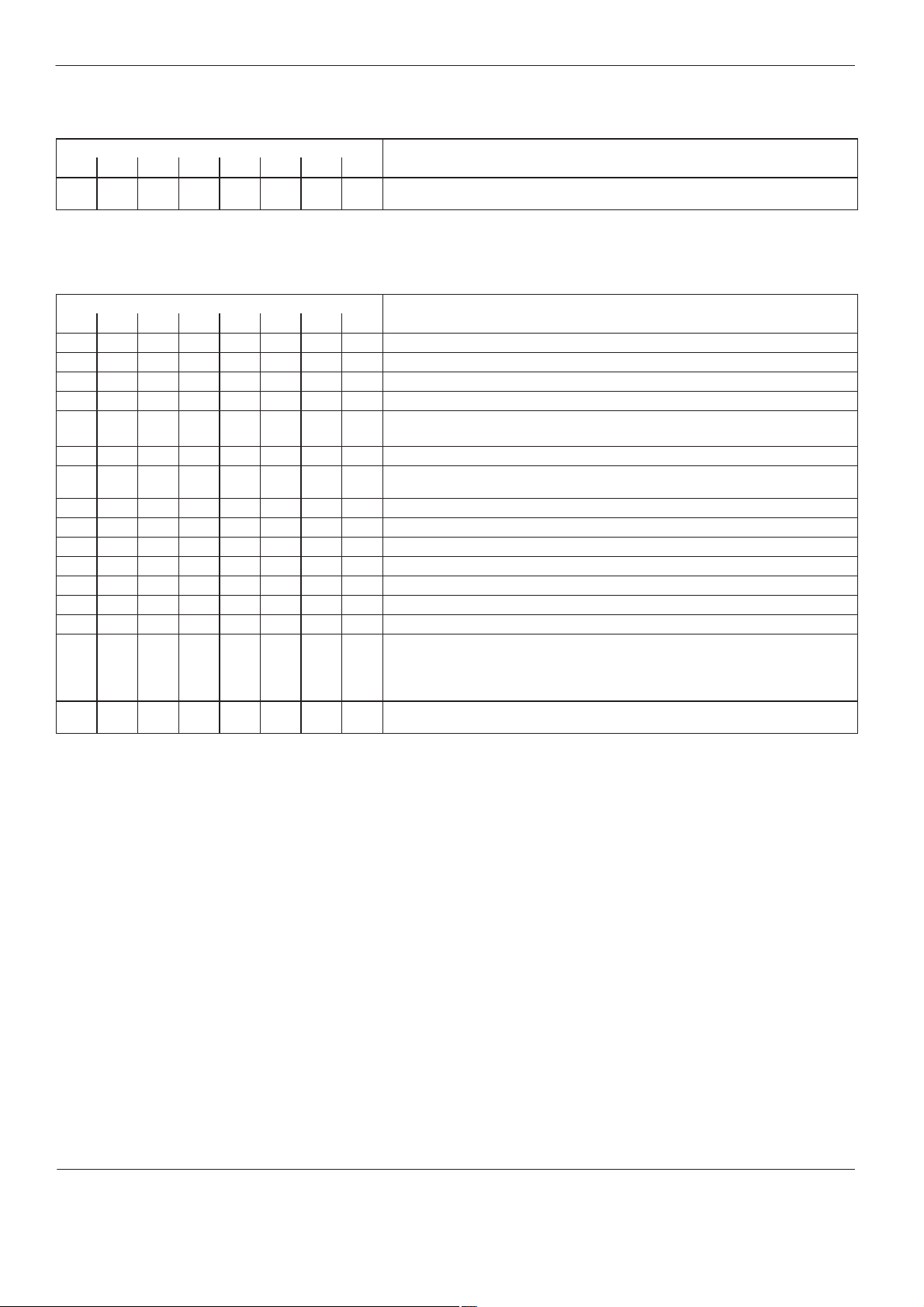
56
Control system CS 20
DIP Switch S 7
Switch
1 2 3 4 5 6 7 8
ON OFF OFF ON ON ON ON OFF Channel number of temperature control panel board (other channel numbers not
permitted)
Function
DIP Switch S 8
Switch Function
1 2 3 4 5 6 7 8
OFF OFF No leading channel
ON OFF Channel 1 is leading channel (refer to table
OFF ON Channel 2 is leading channel (refer to table
ON ON Channel 3 is leading channel (refer to table
OFF Setting by channel deactivated (only SE and offset displayed)
-factory setting-
ON Setting by channel activated
OFF Predefined control parameter (parameter sets) accessible, if
ON Predefined control parameter (parameter sets) blocked
OFF No function
ON No function
OFF Refer to table
ON Refer to table
OFF Inert gas control OFF (only for MX)
ON Inert gas control ON (only for MX)
activated with DIP switch S 8, switch 3
DIP switch S 8, switch 6
DIP switch S 8, switch 6
OFF Immediate shutdown when overtemperature shutdown value
-factory settingNOTE: If the highest temperature setpoint is reduced by 30 °C (54 °F) or more,
shutdown may occur.
ON Shutdown when the shutdown temperature has been exceeded for more than
120 seconds and the temperature continues to rise.
DIP switch S 8, switch 6
DIP switch S 8, switch 6
DIP switch S 8, switch 6
Setting by Channel
OFF
is reached.
)
)
)
is
P/N 412960D
CS03
Issued 07/01
E 2001 Nordson Corporation
All rights reserved

Control system CS 20
57
DIP Switch S 8, Switch 6
Leading channel Switch 6 Initial heating behavior
No leading channel OFF / ON All channels heat independently of one another (no start up control)
Channel 1 OFF The leading channel heats up first. The other channels do not begin to heat until the leading
ON All channels heat up simultaneously with the leading channel, but they can not exceed the
Channel 2 OFF Channel 1 heats simultaneously with the leading channel, but it can not heat to a higher
ON All channels heat up simultaneously with the leading channel, but they can not exceed the
Channel 3 OFF Channels 1 and 2 heat at the same time as the leading channel. However, channels 1 and 2
ON All channels heat up simultaneously with the leading channel, but they can not exceed the
The leading channel is determined by switches 1 and 2 of the DIP switch
S 8
(Refer to
is determined by switch
channel has reached a temperature of 50 C (90 F) below its temperature setpoint. The other
channels can not exceed the actual temperature of the leading channel during the initial
heating phase until the leading channel has reached a temperature of 10 C (18 F) below its
temperature setpoint.
actual temperature of the leading channel until the leading channel has reached a temperature
of 10 C (18 F) below its temperature setpoint.
temperature than that of the leading channel. The other channels do not begin to heat until the
leading channel has reached a temperature of 50 C (90 F) below its temperature setpoint.
The other channels can not exceed the actual temperature of the leading channel during the
initial heating phase until the leading channel has reached a temperature of 10 C (18 F)
below its temperature setpoint.
actual temperature of the leading channel until the leading channel has reached a temperature
of 10 C (18 F) below its temperature setpoint.
can not heat higher than the leading channel. The other channels do not begin to heat until the
leading channel has reached a temperature of 50 C (90 F) below its temperature setpoint.
The other channels can not exceed the actual temperature of the leading channel during the
initial heating phase until the leading channel has reached a temperature of 10 C (18 F)
below its temperature setpoint.
actual temperature of the leading channel until the leading channel has reached a temperature
of 10 C (18 F) below its temperature setpoint.
DIP Switch S 8
6
of the DIP switch
). The initial heating behavior of the channels
S 8
.
Plug Connectors
X1, X2
CAN bus (refer to central module)
E 2001 Nordson Corporation
All rights reserved
CS03
Issued 07/01
P/N 412960D

58
Control system CS 20
4. Temperature Control
Module
Fe-CuNi
Board
Voltage control
of the temperature control
module
One unit may have several temperature control modules. Refer to
Selector Switch S 1
.
For thermoelement temperature sensors Fe-CuNi.
X1 S3 S1 S2
4
3
2
1
C
0 - F
D23
D24
D25
P1
Fig. 31
D10 D11 D12 D13 D14 D15
3
2
1
4
X3 X4 X5
2
1
3456
7 1
345678 9101112
2
DGCO226L134A0399
P/N 412960D
CS03
Issued 07/01
E 2001 Nordson Corporation
All rights reserved

Control system CS 20
59
Pt 100, Ni 120
Board
Voltage Control of
Temperature Control
Module
For temperature sensors Pt 100 or Ni 120.
The temperature control module is different from the temperature control
module
Fe-CuNi
in that it has an additional plug connector X2 and six
switches S.
The temperature control modules for Pt 100 or Ni 120 have different
order numbers.
X1 S3 S1 S2
4
3
2
1
C
0 - F
D23
D24
D25
X2
3
56
2
4
1
S
P1
Fig. 32
D10 D11 D12 D13 D14 D15
3
2
1
4
X3 X4 X5
2
1
3456
7 1
345678
2
9101112
DGCO227L134A0399
E 2001 Nordson Corporation
All rights reserved
CS03
Issued 07/01
P/N 412960D

60
LED’s
Control system CS 20
Number
D 10 Green Lit Heater output of the first channel (plug connector X4) of this temperature control module is switched
D 11 Green Lit Heater output of the second channel (plug connector X4) of this temperature control module is
D 12 Green Lit Heater output of the third channel (plug connector X4) of this temperature control module is
D 13 Green Lit Heater output of the fourth channel (plug connector X4) of this temperature control module is
D 14 Green Lit Heater output of the fifth channel (plug connector X4) of this temperature control module is switched
D 15 Green Lit Heater output of the sixth channel (plug connector X4) of this temperature control module is
D 23 Red Lit A software reset has occured. It can be caused by a brief loss of voltage supply or e.g. by strong,
D 24 Yellow Lit A CAN bus command could not be sent. Check or replace: CAN bus cable and temperature control
D 25 Green Flickering Valid data is being transmitted or received via CAN bus.
Color State Meaning
on. Depending on how switch S 1 is set on the control module, the first channel of this temperature
control module is 1, 7, 13, 19, 25, 31, 37 or 43.
switched on. Depending on how switch S 1 is set on the control module, the second channel of this
temperature control module is 2, 8, 14, 20, 26, 32, 38 or 44.
switched on. Depending on how switch S 1 is set on the control module, the third channel of this
temperature control module is 3, 9, 15, 21, 27, 33, 39 or 45.
switched on. Depending on how switch S 1 is set on the control module, the fourth channel of this
temperature control module is 4, 10, 16, 22, 28, 34, 40 or 46.
on. Depending on how switch S 1 is set on the control module, the fifth channel of this temperature
control module is 5, 11, 17, 23, 29, 35, 41 or 47.
switched on. Depending on how switch S 1 is set on the control module, the sixth channel of this
temperature control module is 6, 12, 18, 24, 30, 36, 42 or 48.
external interfering impulses or glitches (EMC). See also reset of various modules (error number
217 to 239,
Blinking Problems with CAN bus hardware. Check and, if necessary replace CAN bus and modules/boards.
module.
Service Display Error
)
P/N 412960D
CS03
Issued 07/01
E 2001 Nordson Corporation
All rights reserved

V
Oth
V
f
Plug Connectors
Control system CS 20
61
X 1
Connection temperature comparison measuring point
Pin Function Level Notes
1 Voltage supply for temperature comparison measuring point +6 V
2 Signal
3 Reference potential 0 V
DC
approx. 1 VDC at 20 °C
DC
–
–
–
X 2 No function NOTE: Only on temperature control modules Pt 100, Ni 120
X 3 Voltage supply
Pin Level Function
1 +24 V
2 +24 V
3 Reference
potential
4 Reference
DC
DC
Pins 1/2 and 3/4 can be bridged. External components that are connected to the temperature control module are
then supplied via the Bus cable with 24
erwise, Pin 2 and Pin 4 can be connected to an external 24
the temperature control module can thereby be electrically separated from the rest of the control system.
Pin 2 (24 V
to external components) is fuse-protected with a 1 A fuse.
DC
for external components (Refer to X 1 of central module).
DC
voltage supply. The external components o
DC
potential
X 4 Heater outputs 1 to 6
Pin Function Level Pin Funktion Level
1 Voltage supply +24 V
DC
5 Heater channel 4 + Output open collector
2 Heater channel 1 + Output open collector 6 Heater channel 5 + Output open collector
3 Heater channel 2 + Output open collector 7 Heater channel 6 + Output open collector
4 Heater channel 3 + Output open collector
X 5 Temperature sensors 1 to 6
Pin Funktion Pin
1 Temperature sensor channel 1 + 7 Temperature sensor channel 4 +
2 Temperature sensor channel 1 – 8 T emperature sensor channel 4 –
3 Temperature sensor channel 2 + 9 Temperature sensor channel 5 +
4 Temperature sensor channel 2 – 10 Temperature sensor channel 5 –
5 Temperature sensor channel 3 + 11 Temperature sensor channel 6 +
6 Temperature sensor channel 3 – 12 Temperature sensor channel 6 –
CAN bus (refer to central module)
E 2001 Nordson Corporation
All rights reserved
CS03
P/N 412960D
Issued 07/01

62
Control system CS 20
Selector Switch S 1
Position
1 (= Temperature control module 1) 1 to 6 6 (= T emperature control module 6) 31 to 36
2 (= Temperature control module 2) 7 to 12 7 (= Temperature control module 7) 37 to 42
3 (= Temperature control module 3) 13 to 18 8 (= Temperature control module 8) 43 to 48
4 (= Temperature control module 4) 19 to 24 9 to F No function
5 (= Temperature control module 5) 25 to 30
Temperature channel Position Temperature channel
DIP Switch S 2
Switch Function
1 2 3 4 5 6
OFF OFF OFF ON ON ON Channel number ot temperature control module (No other channel numbers permitted).
DIP Switch S 3
Switch Function
1 Position ON: The temperature control module has its own comparison measuring point. It must be connected to the plug
2 to 8 No function
connector X1.
Position OFF: The comparison measuring point must be connected to a different temperature control module.
*) NOTE: The comparison measuring point is connected either to the first temperature control module (selector
switch
Potentiometer P 1
S 1
in position 1) or all modules get a comparison measuring point (refer to wiring diagram).
P1 Factory set
The potentiometer may be adjusted only by Nordson personnel.
Switch S
S Switches S must be closed. NOTE: Only on temperature control modules Pt 100, Ni 120
P/N 412960D
CS03
Issued 07/01
E 2001 Nordson Corporation
All rights reserved

5. Voltage Control of
Temperature Control
Module
D3 F2 F1 D6X1
Control system CS 20
63
DGCO228L096A0399
Fig. 33
Fuses
Fuse Value Order Number
F 1 Operating voltage of
F 2 Operating voltage for external components
Voltage control
board of temperature control module 1 AT P/N 285 957
LED’s
Number Color State Meaning
D 3 Green Lit Fuse F 2
D 6 Green Lit Fuse F 1
Operating voltage of external components
Operating voltage of voltage control board
is correct
is correct
Plug Connectors
X 1 CAN bus (refer to central module)
E 2001 Nordson Corporation
All rights reserved
CS03
Issued 07/01
P/N 412960D

64
Control system CS 20
6. Bar Graph (Option)
D6
F1
X2
X1
For information on the functioning of the bar graph, refer to
Temperature Part
There may be several bar graphs. Refer to
S1 S3
S2
4
C
Selector Switch S 2
Operating the
.
D1
D2
D3
DGCO229L088B0899
Fig. 34 Bar graph, plug side of the board
Fuses
Fuse Value Order Number
F 1 Voltage supply 24 V
DC
1 AT P/N 285 957
LED’s
Number Color State Meaning
D 1 Red Lit A software reset has occured. It can be caused by a brief loss of voltage supply or e.g. by strong,
Blinking Problems with CAN bus hardware. Check and, if necessary replace CAN bus and modules/boards.
D 2 Yellow Lit Problems with CAN bus hardware. Check and, if necessary replace CAN bus and modules/boards.
D 3 Green Flickering Valid data are being transmitted or received via CAN bus.
D 6 Green Lit Fuse F 1
external interfering impulses or glitches (EMC). See also reset of various modules (error number
217 to 239,
Service Display Error
Voltage supply 24 V
)
is correct.
DC
P/N 412960D
CS03
Issued 07/01
E 2001 Nordson Corporation
All rights reserved

Plug Connectors
Control system CS 20
65
X1, X2
CAN bus (refer to central module)
Selector Switch S 2
Position Temperature channel Position T emperature channel
1 (= bar graph 1) 1 to 12 3 (= bar graph 3) 25 to 36
2 (= bar graph 2) 13 to 24 4 (= bar graph 4) 37 to 48
The remaining positions have no function
DIP Switch S 1
Switch Function
1 2 3 4 5 6
ON OFF ON OFF ON ON Channel number of bar graph (No other channel numbers permitted)
E 2001 Nordson Corporation
All rights reserved
CS03
Issued 07/01
P/N 412960D
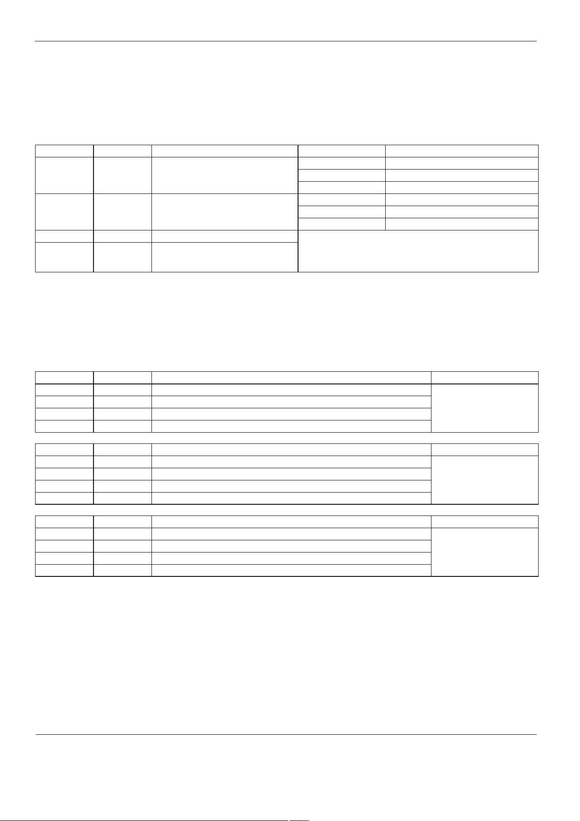
66
1 to 4 C (1.8 to 7.2 F)
2 to 14 C (3.6 to 25.2 F)
4 to 30 C (7.2 to 53 F)
Control system CS 20
DIP Switch S 3
The 8 switches of DIP switch
S 3
are used to set the basic settings of the
bar graph and the deviation values of LEDs 1 to 7. The setting affects all
bar displays.
Basic Settings (Switches 1 and 2)
Switch 1 Switch 2 Basic setting LED (refer to Fig. 12) LED’s light at:
ON OFF Standard setting 1 (Factory setting) LEDs 3 and 5
LEDs 2 and 6 One-half over-/undertemperature value
LEDs 1 and 7 Over-/Undertemperature value
OFF ON Standard setting 2 LEDs 3 and 5
LEDs 2 and 6
LEDs 1 and 7
OFF OFF Bar graph switched off
ON ON Deviation values can be individually set
on switches 3 to 8 (see
)
values
Setting deviation
± 3 °C (5.4 °F) temperature deviation
± 5 °C (9 °F) temperature deviation
± 10 °C (18 °F) temperature deviation
± 15 °C (27 °F) temperature deviation
Setting Deviation Values (Switches 3 to 8)
By adjusting DIP switches 3/4, 5/6 and 7/8, the temperature deviation at
which the LED’s light can be set. The deviation values are added
together (see
Band Widths).
Switch 3 Switch 4 LED’s 3 and 5 light at a temperature deviation of: Band width
OFF OFF
ON OFF
OFF ON
ON ON
Switch 5 Switch 6 LED’s 2 and 6 light at a temperature deviation of: Band width
OFF OFF
ON OFF
OFF ON
ON ON
Switch 7 Switch 8 LED’s 1 and 7 light at a temperature deviation of: Band width
OFF OFF
ON OFF
OFF ON
ON ON
1 °C (1.8 °F)
2 °C (3.6 °F)
3 °C (5.4 °F)
4 °C (7.2 °F)
1°C (1.8 °F) + value of LED's3/5
3 °C (5.4 °F) + value of LED's3/5
5°C (9 °F) + value of LED's3/5
10 °C (18 °F) + value of LED's3/5
2°C (3.6 °F) + value of LED's3/5+value of LED's2/6
4°C (7.2 °F) + value of LED's3/5+value of LED's2/6
8°C (14.4 °F) + value of LED's3/5+value of LED's2/6
16 °C (28.8 °F) + value of LED's3/5+value of LED's2/6
°
°
°
°
°
°
P/N 412960D
CS03
Issued 07/01
E 2001 Nordson Corporation
All rights reserved

7. Temperature Comparison
Measuring Point
Control system CS 20
67
Fig. 35
2
3
1
3
1
2
XXPN064L096A1198
The temperature comparison measuring point is attached to a top hat rail
in the electrical cabinet of the hot melt applicator and is connected to the
plug connector X1 of the temperature control module.
The connections are labeled with numbers: cable terminal 1 of
temperature comparison measuring point to cable clamp 1 of plug
connector, etc.
E 2001 Nordson Corporation
All rights reserved
CS03
Issued 07/01
P/N 412960D

68
Control system CS 20
Technical Appendix of the Motor Part
The
Technical Appendix
equipped for tasks which go beyond the normal operation of the unit.
WARNING: Allow only qualified personnel to perform the
following tasks. Observe and follow the safety instructions in
this document and all other related documentation.
WARNING: Observe all safety instructions concerning handling
of energized components (active parts). Failure to observe may
result in an electric shock.
is meant for personnel who are trained and
P/N 412960D
CS03
Issued 07/01
E 2001 Nordson Corporation
All rights reserved

Control system CS 20
69
1. Central Module with
Digital Input/Output
5
9
V55
F3 F4
V41
V42
V56
1
6
+
2
1
S3
F1
F2
S2
1152
X9
16
R42S15
S1 S6 X13 X11S12
R18
Central Module
V51
V50
V49
V48
The central module with digital input/output is a combination of central
module, digital module and possibly field bus communication module.
The field bus communication module is present only in control systems
with
PROFIBUS DP
(option).
The analog input on the central module must be aligned (Refer to
Aligning Pilot Voltage
V45
V44
V43
V47
X5X3X8
3
2
4
Field Bus Communication
Module
).
S11
1
4
C
V70
F13
Digital module
V67
V69V68 V66V65 V64 V63 V62
UL
ERR
RUN
RDY
V76 V77 V78V75V72 V73 V74V71V53V54
5
2341
X1 X7 X4 X6
9
1
3456
2
6
345678
2
1
1
345678
2
1
X14 X15
345678
2
1
Fig. 36 Plug side (only parts described are shown)
2. Central Module
Fuses
Fuse Value Order Number
F 1 Operating voltage of central module electronics 1 AT P/N 285 957
F 2 Operating voltage of external components
F 3 Incoming supply voltage for electronics 6.3 AT P/N 289 630
F 4 Incoming supply voltage for external components
002879
E 2001 Nordson Corporation
All rights reserved
CS03
Issued 07/01
P/N 412960D

70
Control system CS 20
LED’s
Number Color State Meaning
V 41 Green Lit Fuse F 1
V 42 Green Lit Fuse F 2
V 43 Green Lit Input X 4 / Pin 4 is active
V 44 Green Lit Input X 4 / Pin 5 is active
V 45 Green Lit Input X 4 / Pin 3 is active
V 47 Green Lit Relay for output X 4 / Pin 6, X 4 / Pin 7, X 4 / Pin 8 has picked up
V 48 Green Lit Input X 4 / Pin 2 is active
V 49 Green Flickering Valid data are being transmitted or received via CAN bus.
V 50 Yellow Lit A CAN bus command could not be sent. Check or replace: CAN bus cable and central module.
V 51 Red Lit A software reset has occured. It can be caused by a brief loss of voltage supply or e.g. by strong,
external interfering impulses or glitches (EMC). See also reset of various modules (error number
217 to 239,
Blinking Problems with CAN bus hardware. Check and, if necessary replace CAN bus and modules/boards.
V 53 Green Lit Relay for output X 6 / Pin 4, X 6 / Pin 5, X 6 / Pin 6 has picked up
V 54 Green Lit Relay for output X 6 / Pin 1, X 6 / Pin 2, X 6 / Pin 3 has picked up
V 55 Green Lit Fuse F 3
V 56 Green Lit Fuse F 4
Operating voltage of electronics is
Operating voltage of external components
Service Display Error
Supply voltage for electronics
Supply voltage for external components
)
correct
is correct
is correct
is correct
Potentiometer R 18, R 42
R 18 Align pilot voltage input 0 to 10 VDC (Refer to
R 42 Align pilot voltage input 0 to 160 VDC (Refer to
Aligning Pilot Voltage
Aligning Pilot Voltage
)
)
DIP Switch S 1
Switch Function
1 2 3 4
ON ON OFF ON Channel and module number of the central module (other switch positions not permitted)
P/N 412960D
CS03
Issued 07/01
E 2001 Nordson Corporation
All rights reserved

Control system CS 20
DIP Switch S 6
Switch Function
1 2 3 4 5 6 7 8
OFF OFF – – – Factory setting, values and parameters are displayed and can be altered. Service
display can also be activated.
ON OFF – – – Values and parameters are displayed and can be altered. Service display cannot be
activated.
OFF ON – – – Values and parameters can only be displayed; they cannot be altered.
ON ON – – – Only the software version number and the DIP switch positions on the central
module can be displayed.
OFF – – – No function
ON – – – No function
OFF – – – Automatic mode: If the speed setpoint is below 1.0 min-1 or below rLo, the motor
runs at 1 min-1 or at speed rLo.
Manual mode: No function
ON – – – Automatic mode: If speed setpoint is below 1.0 min-1 or below rLo, the motor does
not run.
Manual mode: No function
(Factory setting)
OFF – – – Parameters rLo and Uhi are activated
ON – – – Parameters rLo and Uhi are factory set and cannot be changed (rLo = 1.0 min-1,
Uhi = 100 % pilot voltage)
71
Button S 3
Switch S 2
Switch position outward (factory setting) Normal operation
Switch position inward Switch position permitted only for Nordson personnel
Pressing the button activates a software reset.
The switch position first takes effect following a software reset.
Switch S 15
OFF Input voltage 0 to 160 V
ON Input voltage 0 to 10 VDC pilot voltage (factory setting)
pilot voltage
DC
E 2001 Nordson Corporation
All rights reserved
CS03
Issued 07/01
P/N 412960D

72
against reversing of olarity behind the fuses with a rotective diode
gg
the operating voltage of external components. All external components have the
Potential free in relation to 24 V
DC
su ly. The in ut is su lied internally via a
Control system CS 20
Plug Connectors
X 1
Voltage supply
Pin Function Level Notes
1 Input for operating voltage of
electronics
2 Reference potential for Pin 1 0 V
3 Input for operating voltage of
external components
4 Reference potential for Pin 3 0 V
+24 V
DC
+24 V
DC
DC
DC
Both voltages are electrically isolated from one another and are led through the
CAN bus cable. Pin 1 / 3 are fuse protected internally with 6.3 A and protected
The operating voltage for the electronics may only be used for the boards/modules
of the control system.
The inputs/outputs of all boards/modules of the control system are operated with
same reference potential (Pin 4).
X 3 Pilot voltage input
Pin Function Level Notes
1 Pilot voltage input 0 to 10 VDC or
2 Reference potential for pilot
voltage input
0 to 160 V
0 V
DC
DC
Also refer to
Potential free in relation to 24 V
DC/DC transducer.
X 4 Interface
Pin Function Level Notes
1 Must be switched to the
optocoupler inputs to activate
+24 V
DC
Reference potential is the reference voltage of the external components of the
control system
them
2 Input for mode switch Input
optocoupler
With the mode switch on the Nordson unit, one of the two modes can be selected:
Stand alone mode
stopped because of the startup protection being activated. For information on
Stand alone mode
3 No function – –
4 No function – –
5 No function – –
6 Inert gas for MX units Relay change
over contact
7 No function Relay break
The relay engages when the solenoid valve is to be activated to supply the tank
with inert gas.
NOTE: Only for MX units with the option
contact
8 Inert gas for MX units Relay make
contact
p
Aligning pilot voltage
p
or
Remote mode
and
Remote mode
p
p
supply. The input is supplied internally via a
.
p
. When the mode is changed, all drives are
, also refer to
Communication Data List
Inert gas equipment
.
P/N 412960D
Issued 07/01
CS03
E 2001 Nordson Corporation
All rights reserved
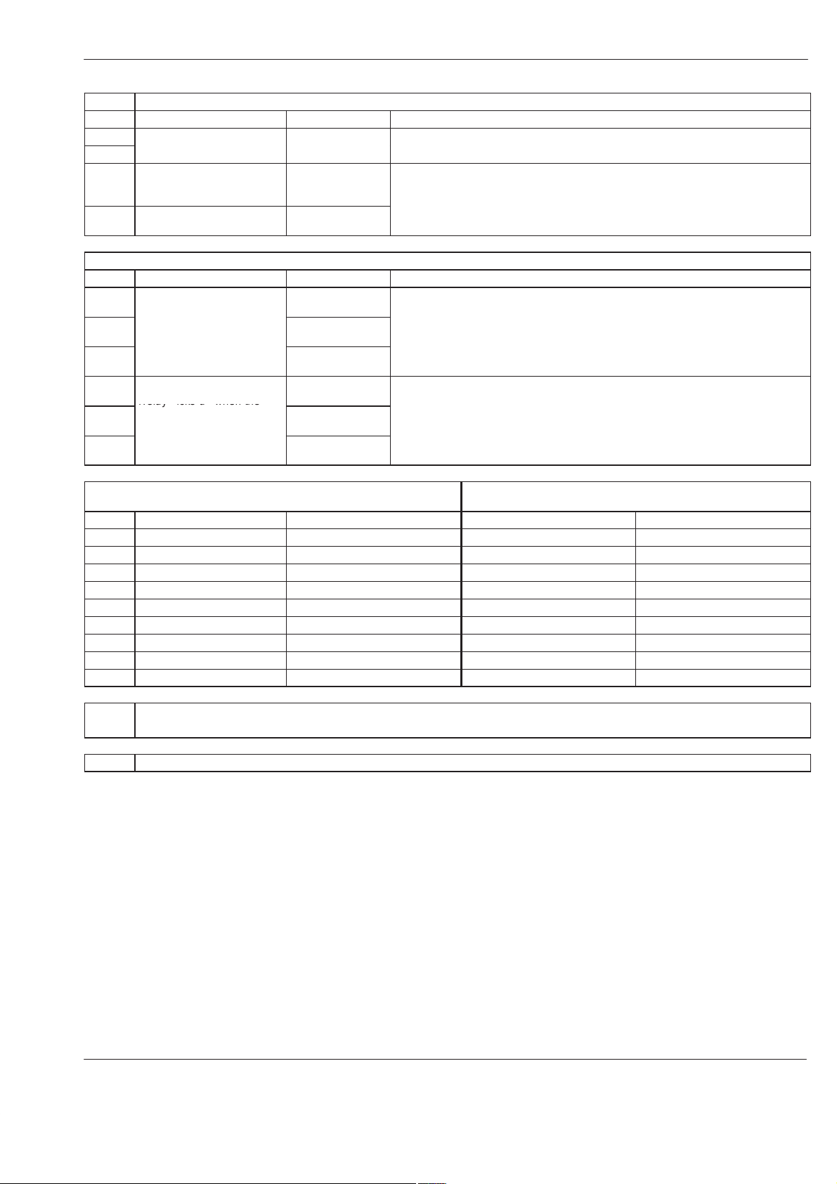
Control system CS 20
Relay icks u when the
73
X 5
Interface to main contactor
Pin Funktion Level Notes
1 Relay picks up when main
2
contactor should pick up contact
3 Input must be active when
main contactor has picked
Relay make
Capacity: 250 V
Input optocoupler Serves to monitor the main contactor and the function
OFF by the thermostate.
AC
/ 2 A
Overtemperature switch
up
4 Must be switched to the
optocoupler to activate it
+24 V
DC
X 6 Outputs Indicator beacon (Indicator beacon is optional)
Pin Function Level Notes
1 Indication
operation
2
Relay picks up when the
system is ready for
3
operation (green indication
lamp is lit)
4 Indication
Relay picks up when the
5
system has recognized an
error (red indication lamp is
6
lit)
Ready for
Collective fault
Relay change over
contact
Relay break
contact
Relay make
contact
Relay change over
contact
Relay break
contact
Relay make
Capacity: 250 V
Capacity: 250 V
AC
AC
/ 2 A
/ 2 A
contact
X 7 RS 232-Interface (use only permitted by Nordson
Corresponds to PC-Interface
personnel)
Pin Function Notes 9-pin 25-pin
1 – – – –
2 TXD Transmittal data Pin 2 (RXD) Pin 3 (RXD)
3 RXD Received data Pin 3 (TXD) Pin 2 (TXD)
4 DTR Always active Not needed Not needed
5 Reference potential – Pin 5 (Ground) Pin 5 (Ground)
6 – – – –
7 – – – –
8 RTS Always active Not needed Not needed
9 – – _ –
X 8 Optional software expansion module
for functions
high temperature, reverse mode, threshold value switch
X 9 Internal plug
E 2001 Nordson Corporation
All rights reserved
CS03
Issued 07/01
P/N 412960D

74
com onents
boards/modules
The in ut of the central module (X1 / Pin 3, +24 VDC) is connected to these ins
b
The i
Control system CS 20
Plug connector
CAN bus
Pin Function Level Notes
1 Data CAN High The CAN bus is electrically connected to the processor potential
9 Data reference potential CAN 0 V
2 Data CAN Low
10 – +24 V
3
11
4 – 0 VDC electronics Voltage supply of processors on the boards and modules.
12
5
13 – +24 VDC externalpVoltage supply of external components and the inputs/outputs of the
6
14
7 – 0 VDC external
15
8
Aligning Pilot Voltage
(contd.)
DC
DC
electronics
components
(see central module, X 1 / Pin 2)
Voltage supply of processors on the boards and modules.
The input of the central module (X1 / Pin 1, +24 VDC) is connected to these pins
through a 6.3 A fuse.
The input of the central module (X1 / Pin 2, Ground) is connected with these pins.
.
p
through a 6.3 A fuse.
Voltage supply of external components and the inputs/outputs of the
oards/modules.
nput of the central module (X1 / Pin 4, Ground) is connected with these pins.
Before aligning the pilot voltage input, it must be determined whether pilot
voltage is 0 to 10 VDC or 0 to 160 VDC.
p
Aligning Pilot Voltage Input 0 to 10 V
1. Ensure that switch
S 15
is set to ON (factory setting).
DC
2. Operate parent machine at max. speed.
3. Display
4. Set
Uin
for Motor 1 (see
Uin
with potentiometer
Service Displays
R 18
to 100 (100% pilot voltage).
Aligning Pilot Voltage Input 0 to 160 V
1. Set switch
2. Operate parent machine at max. speed.
3. Display
4. Set
Uin
S 15
to
OFF
.
Uin
for Motor 1 (see
with potentiometer
Service Displays
R 42
to 100 (100% pilot voltage).
DC
).
).
P/N 412960D
Issued 07/01
CS03
E 2001 Nordson Corporation
All rights reserved

3. Digital Module
Fuses
Control system CS 20
75
Fuse
F 13 Incoming supply voltage for external components digital I/O 1 AT P/N 285 957
Value Order Number
LED’s
Number Color State Meaning
V 62 Green Lit Input 1 (X 11 / Pin 2) is active
V 63 Green Lit Input 2 (X 11 / Pin 3) is active
V 64 Green Lit Input 3 (X 11 / Pin 4) is active
V 65 Green Lit Input 4 (X 11 / Pin 5) is active
V 66 Green Lit Input 5 (X 11 / Pin 6) is active
V 67 Green Lit Input 6 (X 11 / Pin 8) is active
V 68 Green Lit Input 7 (X 11 / Pin 9) is active
V 69 Green Lit Input 8 (X 11 / Pin 10) is active
V 70 Green Lit Fuse F 13
V 71 Green Lit Output 1 (X 14 / Pin 1 and 2) is active
V 72 Green Lit Output 2 (X 14 / Pin 3 and 4) is active
V 73 Green Lit Output 3 (X 14 / Pin 5 and 6) is active
V 74 Green Lit Output 4 (X 14 / Pin 7 and 8) is active
V 75 Green Lit Output 5 (X 15 / Pin 1 and 2) is active
V 76 Green Lit Output 6 (X 15 / Pin 3 and 4) is active
V 77 Green Lit Output 7 (X 15 / Pin 5 and 6) is active
V 78 Green Lit Output 8 (X 15 / Pin 7 and 8) is active
Supply voltage for external components digital I/O
is correct
DIP Switch S 12
Switch Function
1 2 3 4 5 6
OFF ON OFF ON ON ON Channel number of the digital module (other channel numbers not permitted)
E 2001 Nordson Corporation
All rights reserved
CS03
Issued 07/01
P/N 412960D

76
Pl
Control system CS 20
Selector Switch S 11
Standard units Notes
Position Function Description of functions/special functions
1 For units 1x1, 2x1, 3x1 and 4x1
2 For units 5x1, 6x1 (special function)
3 For units 1x2 and 2x2 together with digital module no.1
4 For units 3x2, 4x2 together with digital module no.3
Special units
Position Function
5 Special units 1 A (Motor 1 to 3)
6 Special units 1 B (Motor 4 to 6)
7 Special units 2 A
8 Special units 3 A
9 Special units 4 A
A Special units 5 A
B MC standard units
C to F No function
Plug Connectors
Corresponds to
The inputs must be connected to 24 VDC switching voltage in order to
selector switch S 1
on separate digital module.
refer to
ug connector
activate each function.
X 11
Pin Level Units
1 +24 V
2 Optocoupler
3 Optocoupler Release
4 Optocoupler Temperature setback – Temperature setback –
5 Optocoupler Release
6 Optocoupler Release
7 +24 V
8 Optocoupler – – – –
9 Optocoupler Release
10 Optocoupler Release
Inputs of standard units (see also
1x1 to 4x1
Selector switch S 11
Position 1
DC
DC
Switching voltage Switching voltage Switching voltage Switching voltage
Release
All motors
Motor 1
Motor 2
Switching voltage Switching voltage Switching voltage Switching voltage
Motor 3
Motor 4
Function of input signals
5x1 and 6x1
Selector switch S 11
Position 2
–
– Release
Release
Release
– – –
– – –
Motor 5
Motor 6
)
Units
Units
1x2 and 2x2
Selector switch S 11
Position 3
Release
All motors
Release
Release
Motor 1
Motor 2
Units
3x2 and 4x2
Selector switch S 11
Position 4
–
–
Release
Release
Motor 3
Motor 4
P/N 412960D
CS03
Issued 07/01
E 2001 Nordson Corporation
All rights reserved

Control system CS 20
77
X 11
Pin Level Special units 1 A
1 +24 V
2 Optocoupler No temperature setback –
3 Optocoupler Collective manual mode – Release
4 Optocoupler Release
5 Optocoupler Release
6 Optocoupler Release
7 +24 V
8 Optocoupler No collective coupling
9 Optocoupler Reset coupling fault
10 Optocoupler
X 11
Pin Level Special units 4 A Special units 5 A Special units 6 A
1 +24 V
2 Optocoupler Manual mode
3 Optocoupler Manual mode
4 Optocoupler Manual mode
Inputs of special units (see also
Motor 1 to 3
Selector Switch S 11
Position 5
DC
Switching voltage Switching voltage Switching voltage Switching voltage
Motor 1
Motor 2
Motor 3
DC
Inputs of special units (see also
DC
Switching voltage Switching voltage Switching voltage Switching voltage
fault
through flank
Release
Selector Switch S 11
Position 9
Switching voltage Switching voltage Switching voltage
Function of input signals
Special units 1 B
Selector Switch S 11
Release
Release
Release
– Collective automatic mode Release
– Release
– Release
Function of input signals
Selector Switch S 11
Motor 1
Motor 2
Motor 3
No unit specific alarm
(e.g. fuse alarm)
Pressure monitoring Safety valve
Pressure build-up Refer to
)
Motor 4 to 6
Position 6
Motor 4
Motor 5
Motor 6
)
Position A
Special units 2 A Special units 3 A
Selector Switch S 11
Position 7
Release Release
All motors
Temperature setback Temperature setback
Release
Release
Motor 1
Motor 2
Motor 3
Motor 4
MC standard units
Selector Switch S 11
Position B
MC Standard
Units
5 Optocoupler Manual mode
6 Optocoupler Coupling fault
Motor 4
Motor 1
Pressure control Safety valve
Safety valve opened
Motor 1
7 +24 V
8 Optocoupler Coupling fault
DC
Switching voltage Switching voltage Switching voltage
Motor 2
Safety valve opened
Motor 2
9 Optocoupler Coupling fault
Motor 3
Safety valve opened
Motor 3
10 Optocoupler Coupling fault
Motor 4
Safety valve opened
Motor 4
1x1 to 4x1
Selector Switch S 11
Position 8
Release
Release
Release
All motors
Motor 1
Motor 2
Motor 3
Release
Reset coupling fault
statically
Safety valve
open, motor 1
Motor 4
Special units 7 A
Double stream pumps
Selector Switch S 11
Position C
Pump stream A
Pump stream B
open, motor 1
Safety valve
open, motor 2
Pump stream A
Pump stream B
open, motor 2
Safety valve
open, motor 3
Safety valve
open, motor 3
Pressure monitoring
Free
Pump stream A
Pump stream B
E 2001 Nordson Corporation
All rights reserved
CS03
Issued 07/01
P/N 412960D

78
V
Oth
V
f
system
Control system CS 20
Plug connector
X 13
Pin Level Function
1 +24 V
2 +24 V
3 Reference
4 Reference
Voltage supply digital I/O
potential
potential
DC
DC
(contd.)
Pins 1/2 and 3/4 can be bridged. External components connected to the central module with digital input/output are
then supplied via the bus cable with 24
erwise, an external 24
the central module with digital input/output can thereby be electrically separated from the rest of the control
.
Pin 2 (24 V
to external components) is fuse-protected with a 1 A fuse.
DC
voltage supply can be connected to Pin 2 and Pin 4. The external components o
DC
(Refer to X 1 of the central module).
DC
The outputs switch when the function is active or when the operating
mode has been reached.
X 14
Pin Switching state Units 1x1 to 4x1 Units 5x1 and 6x1 Units 1x2 and 2x2 Units 3x2 and 4x2
1 / 2 Relay output 1 Unit ready for operation No undertemperature Unit ready for operation –
3 / 4 Relay output 2 Collective fault No Overtemperature Collective fault –
5 / 6 Relay output 3 No temperature setback No collective fault No temperature setback –
7 / 8 Relay output 4 Release
Outputs of standard units (see also
Selector switch S 11
Position 1
Control unit
Function of output signals
Selector switch S 11
Position 2
– Release
)
Selector switch S 11
Position 3
Control unit
Selector switch S 11
Position 4
–
X 14
Pin Switching state Special units 1 A
1 / 2 Relay output 1 No undertemperature – Unit ready for operation Motors ready for operation
3 / 4 Relay output 2 No overtemperature – Collective fault Collective fault
5 / 6 Relay output 3 No collective fault – No temperature setback No temperature setback
7 / 8 Relay output 4 No coupling fault – Release
X 14
Pin Switching state Special units 4 A Special units 5 A Special units 6 A
1 / 2 Relay output 1 Motor 1 runs in manual
3 / 4 Relay output 2 Motor 2 runs in manual
5 / 6 Relay output 3 Motor 3 runs in manual
7 / 8 Relay output 4 Motor 4 runs in manual
Outputs of special units (see also
Motor 1 to 3
Selector Switch S 11
Position 5
Outputs of special units (see also
Selector Switch S 11
Position 9
mode
mode
mode
mode
Function of output signals
Special units 1 B
Motor 4 to 6
Selector Switch S 11
Position 6
Function of output signals
Selector Switch S 11
Position A
No unit specific alarm
(e.g. fuse alarm)
No overpressure Refer to
No underpressure No underpressure
Pressure build-up ready Free
)
Special units 2 A Special units 3 A
1x1 to 4x1
Selector Switch S 11
Position 7
Control unit
Selector Switch S 11
Position 8
Release
Control unit
)
Special units 7 A
MC standard units
Selector Switch S 11
Position B
MC Standard
Units
Double stream pumps
Selector Switch S 11
Position C
All safety valves closed
No overpressure
P/N 412960D
CS03
Issued 07/01
E 2001 Nordson Corporation
All rights reserved

Control system CS 20
79
X 15
Pin Switching state Units 1x1 to 4x1 Units 5x1 and 6x1 Units 1x2 and 2x2 Units 3x2 and 4x2
1 / 2 Relay output 5 Motor 1 rotates Motor 5 rotates Motor 1 rotates Motor 3 rotates
3 / 4 Relay output 6 Motor 2 rotates Motor 6 rotates Motor 2 rotates Motor 4 rotates
5 / 6 Relay output 7 Motor 3 rotates – Motor 1 rotates Motor 3 rotates
7 / 8 Relay output 8 Motor 4 rotates – Motor 2 rotates Motor 4 rotates
X 15
Pin Switching state Special units 1 A
1 / 2 Relay output 5 No motor fault No temperature setback Motor 1 rotates Motor 1 rotates
3 / 4 Relay output 6 Motor 1 rotates Motor 4 rotates Motor 2 rotates Motor 2 rotates
5 / 6 Relay output 7 Motor 2 rotates Motor 5 rotates Motor 3 rotates Motor 3 rotates
7 / 8 Relay output 8 Motor 3 rotates Motor 6 rotates Motor 4 rotates Motor 4 rotates
X 15
Pin Switching state Special units 4 A Special units 5 A Special units 6 A Special units 7 A
1 / 2 Relay output 5 Motor fault
3 / 4 Relay output 6 Motor fault
Outputs of standard units (see also
Selector switch S 11
Position 1
Outputs of special units (see also
Motor 1 to 3
Selector Switch S 11
Position 5
Outputs of special units (see also
Selector switch S 11
Position 9
Motor 1
Motor 2
Function of output signals
Selector switch S 11
Position 2
Function of output signals
Special units 1 B
Motor 4 to 6
Selector Switch S 11
Position 6
Function of output signals
Selector switch S 11
Position A
Safety valve open
Safety valve open
)
Selector switch S 11
Position 3
Selector switch S 11
Position 4
)
Special units 2 A Special units 3 A
1x1 to 4x1
Selector Switch S 11
Position 7
Selector Switch S 11
Position 8
)
Motor 1
Motor 2
Selector switch S 11
Position B
Refer to
MC Standard
Selector switch S 11
Position C
Free
Free
Units
5 / 6 Relay output 7 Motor fault
7 / 8 Relay output 8 Motor fault
Motor 3
Motor 4
Safety valve open
Safety valve open
Motor 3
Motor 4
Free
Free
E 2001 Nordson Corporation
All rights reserved
CS03
Issued 07/01
P/N 412960D

80
module cannot be used to switch to automatic mode
Control system CS 20
Function of Input Signals
Release
Unit
Level Function Notes
0 V
24 V
Release
Level Function Notes
0 V
24 V
Temperature setback
Level Function Notes
0 V
24 V
Main contactor is not switched on; heaters and motors are
DC
switched off. In display 30 (Fig. 1), OFF appears.
After approx. 2 seconds the relay for X5, Pin 1 / 2 on the central
DC
module closes and the main contactor (load current circuit for
heaters and motors) is switched on.
All motors
All motors are blocked even when the unit/system is ready for
DC
operation.
All pre-selected motors are released when the unit/system is
DC
ready for operation.
No temperature setback Also refer to
DC
After approx. 2 seconds, the temperature setback is switched on.
DC
All channels are set back by the set value. The motors are
stopped and the motor startup protection is activated. In display 4
and 30 (Fig. 1), SPL appears.
The electronics are supplied with voltage. The load current circuit
for heaters and motors is switched off.
–
The input must be switched from 0 V
deactivate the motor startup protection.
See also
See also
DC
to 24 V
in order to
DC
Operating the motor part, motor startup protection.
Switching temperature setback on/off.
Operating the temperature part, parameter overview.
No temperature setback
Level Function Notes
0 V
After approx. 2 seconds, the temperature setback is switched on.
DC
All channels are set back by the set value. The motors are
stopped and the motor startup protection is activated. In display 4
Also refer to
See also
and 30 (Fig. 1), SPL appears.
24 V
Release
No temperature setback
DC
Motor 1 to 6
Level Function Notes
0 V
24 V
Manual mode
The corresponding motor is blocked. See also
DC
The corresponding motor is pre-selected.
DC
Motor 1 to 6
Level Function Notes
0 V
Automatic mode of the corresponding motor Manual mode supersedes automatic mode; this means:
DC
– If manual mode was activated on the control panel, the digital
24 V
Manual mode of the corresponding motor
DC
– If the digital module was used to switch to manual mode,
automatic mode cannot be activated on the control panel.
Switching temperature setback on/off.
Operating the temperature part, parameter overview.
Operating the motor part, switching on motors.
.
P/N 412960D
CS03
Issued 07/01
E 2001 Nordson Corporation
All rights reserved

Collective automatic mode
order for the coupling to engage. The error message remains
order for the coupling to engage. The error message remains
Level Function Notes
0 V
24 V
Manual mode active for all motors. The speed is equal to the set
DC
value and is held stable.
Automatic mode active for all motors. The speed is controlled by
DC
pilot voltage. The parameters rLo, rHi and Uhi can be set.
The possibility to switch between manual and automatic mode on
the control panel is deactivated if this input is present in the
control system.
Collective manual mode
Level Function Notes
0 V
24 V
Automatic mode active for all motors. The speed is controlled by
DC
pilot voltage. The parameters rLo, rHi and Uhi can be set.
Manual mode active for all motors. The speed is equal to the set
DC
value and is held stable.
The possibility to switch between manual and automatic mode on
the control panel is deactivated if this input is present in the
control system.
No collective coupling fault
Level Function Notes
0 V
Coupling fault When a coupling fault occurs, CLU (error number 64) appears in
DC
display 30 (Fig. 1).
When a coupling fault occurs, the motors continue to rotate in
24 V
No coupling fault
DC
even after the coupling has engaged until it is reset via the
corresponding digital input or the automatic reset is activated via
the corresponding digital input.
Control system CS 20
81
p
Coupling fault
Motor 1 to 6
Level Function Notes
0 V
No coupling fault When a coupling fault occurs, CLU (error number 64) appears in
DC
display 30 (Fig. 1).
When a coupling fault occurs, the motors continue to rotate in
24 V
DC
Coupling fault
even after the coupling has engaged until it is reset via the
corresponding digital input or the automatic reset is activated via
the corresponding digital input.
Reset coupling fault statically
Level Function Notes
0 V
24 V
An indicated coupling fault is not automatically reset. The error
DC
message CLU and error number remain.
An indicated coupling fault is automatically reset when the cou-
DC
pling has re-engaged. The error message CLU and error number
–
are deleted.
p
E 2001 Nordson Corporation
All rights reserved
CS03
Issued 07/01
P/N 412960D

82
ifi
244)
ressure monitoring for under ressure, Phi and PAH = ressure
ill. Th
setting arameter PSP to OFF. PSL, PSH, PAL, PAH are not
Control system CS 20
Function of Input Signals
(contd.)
Reset coupling fault through flank
At this input, a flank of 0 VDC to 24 V
indicates a coupling fault.
NOTE: To deactivate the startup protection, this flank must be set once after the initial heating phase or after an error indication.
No unit specific alarm (e.g. fuse alarm)
Level Function Notes
0 V
24 V
At least one fuse has been activated When there is 0 VDC at the input, all motors are stopped and the
DC
All fuses are OK
DC
Pressure monitoring
Level Function Notes
0 V
24 V
Pressure monitoring not active See
DC
Pressure monitoring active
DC
must appear to reset a coupling fault. The fault is only reset when the input
DC
output
Unit spec
c alarm
is activated (error number
Operating the motor part, parameter overview
p
monitoring for overpressure.
Coupling fault
p
no longer
.
, Plo and PAL =
p
Pressure build-up
Level Function Notes
0 V
24 V
Pressure build-up not active, normal unit function. This function serves to maintain a certain pressure in the
DC
Pressure build-up active. The respective motor runs at the speed
DC
set in parameter rhi until the corresponding safety valve has
opened (see
Input safety valve motor 1 to 6 open
safety valve, the motor runs at a speed of 5 min-1. If the safety
valve closes again, the corresponding motor continues to run at
the speed set in parameter rhi until the safety valve opens again.
When all safety valves have opened once, the output
build-up complete
is closed.
). With open
Pressure
application system even at machine standst
safety valves must be set to the desired pressure.
Function only together with special safety valve which is equipped
with an electrical contact.
Pressure build-up
control function being activated.
Pressure control
Level Function Notes
0 V
24 V
Pressure control not active Pressure control can be deactivated for individuell drives by
DC
Pressure control active
DC
displayed any more. The drives are then speed controlled.
e pneumatic
is not activated for the drives with pressure
p
P/N 412960D
CS03
Issued 07/01
E 2001 Nordson Corporation
All rights reserved

Control system CS 20
dis lay 30 (Fig. 1) of the corres onding motor anel (error
83
Safety valve open
Motor 1 to 6
Level Function Notes
0 V
Safety valve closed (normal operating mode) When the safety valve is open, the error message bPo appears in
DC
display 30 (Fig. 1) of the corresponding motor panel (error
number 243).
24 V
Safety valve open
DC
The error message bPo only appears if the function
build-up
the function
Safety valve
Pump stream A
(or B) open, motor 1 to 3
Level Function Notes
0 V
24 V
Safety valve closed (normal operating mode) When the safety valve is open, the error message bPo appears in
DC
Safety valve open
DC
p
number 243).
is not active. The output
Pressure build-up
is active.
Safety valve
p
Pressure
also switches when
p
E 2001 Nordson Corporation
All rights reserved
CS03
Issued 07/01
P/N 412960D

84
for o eration in certain cases (e.g. when cou ling fault or
serves to release the a lication heads and is normally required
Control system CS 20
Function of Output Signals
Unit ready for operation
Switching state Function Notes
Open Unit not ready for operation –
Closed Unit ready for operation
Collective fault
Switching state Function Notes
Open No fault If the output
Closed Fault, unit is not ready for operation
No temperature setback
Switching state Function Notes
Open Temperature setback –
Closed No temperature setback
p
overtemperature occur).
Ready for operation
is also active, the unit is ready
p
Release
Switching state Function Notes
Open Control unit blocked The relay picks up as soon as at least one motor rotates.
Closed Control unit released
Motor 1 to 6 rotates
Switching state Function Notes
Open Motor does not turn The relay picks up as soon as the motor rotates. This signal
Closed Motor rotates
No undertemperature
Switching state Function Notes
Open Undertemperature message from at least one channel –
Closed No undertemperature message from temperature con-
No Overtemperature
Switching state Function Notes
Open Overtemperature indication from at least one channel –
Closed No overtemperature indication from temperature con-
Control unit
pp
in the electrical cabinet.
troller
troller
P/N 412960D
CS03
Issued 07/01
E 2001 Nordson Corporation
All rights reserved

Control system CS 20
No coupling fault
Switching state Function Notes
Open Coupling fault not yet reset See inputs
Closed No coupling fault
No motor fault
Switching state Function Notes
Open General motor fault Speed alarm, motor overtemperature, coupling fault
Closed No motor fault –
Coupling fault
85
Motor fault
Switching state Function Notes
Open No fault in the corresponding motor The relay picks up when there is a fault in the corresponding
Closed Fault in the corresponding motor
No collective fault
Switching state Function Notes
Open Error, unit is not ready for operation –
Closed Unit ready for operation
Motors ready for operation
Switching state Function Notes
Open Unit not ready for operation The relay picks up when:
Closed Unit ready for operation
Motor rotates in manual mode (Motor 1, Motor 2 etc.)
Switching state Function Notes
Open The corresponding motor is not in manual mode or
Closed The corresponding motor is in manual mode and rotates
Motor 1 to 6
motor (e.g. speed fault, coupling fault, motor overtemperature).
- no fault indication present
- all motors on the control panel are pre-selected
- all motors on the control panel are set to automatic mode.
–
doesn’t rotate
No unit specific alarm, (e.g. fuse alarm)
Switching state Function Notes
Open At least one fuse has been activated See input
Closed All fuses are OK
E 2001 Nordson Corporation
All rights reserved
CS03
Issued 07/01
Unit specific alarm
P/N 412960D

86
gg
gg
Control system CS 20
Function of Output Signals
(contd.)
No overpressure
Switching state Function Notes
Open Overpressure or pressure monitoring not active See input
No overpressure
Closed No overpressure
No underpressure
Switching state Function Notes
Open Underpressure or pressure monitoring not active See input
Closed No underpressure
Pressure build-up ready
Switching state Function Notes
Open Pressure build-up not yet ready See input
Closed Pressure build-up ready
active and no overpressure alarm present. The output is switched
off if pressure monitoring is not active.
No underpressure is being activated if pressure monitoring is
active and no underpressure alarm present. The output is
switched off if pressure monitoring is not active.
Pressure monitoring
is being activated if pressure monitoring is
Pressure monitoring
Pressure build-up
Safety valve open (Motor 1, Motor 2 etc.)
Switching state Function Notes
Open Safety valve open See input
Closed Safety valve closed (normal operating mode)
All safety valves are closed (for all motors)
Switching state Function Notes
Open Safety valve open Relay contact closes when all safety valves have closed.
Closed Safety valve closed (normal operating mode)
Safety valve open
P/N 412960D
CS03
Issued 07/01
E 2001 Nordson Corporation
All rights reserved

Control system CS 20
(
87
3. Digital Module
(contd.)
In addition to the digital module that is part of the central module with
digital input/output, units with special functions can have additional
separate digital modules.
The levels/switching states of the inputs and outputs can be shown in
hexadecimal code in the service display of the motor part (Refer to
service displays
X3
F2
F1
D21
D12
S1
4
C
F3
D20
D50
D14
D13
D15
di
and do).
S2
1
15
D11
2
16
D16
X1
D10
D7
D9
D8
D18
D17
D4
D6
D5
D3
D2
D1
D19
345678
2
1
X4
345678
2
1
X5
MXCO026L089B0200
Fig. 37 Separate digital module
Fuses
Separate Digital Module)
Fuse Value Order Number
F 1 Operating voltage of digital module electronics 1 AT P/N 285 957
F 2 Operating voltage for external components
F 3 Operating voltage for external components
E 2001 Nordson Corporation
All rights reserved
CS03
Issued 07/01
P/N 412960D

88
(
(
(
(
Control system CS 20
LED’s
Separate Digital Module)
Number
D 1 Red Lit A software reset has occured. It can be caused by a brief loss of voltage supply or e.g. by strong,
D 2 Yellow Lit A CAN bus command could not be sent. Check or replace: CAN bus cable, central module and
D 3 Green Flickering Valid data are being transmitted or received via CAN bus.
D 4 Green Lit Input 1 (X 1 / Pin 2) is active
D 5 Green Lit Input 2 (X 1 / Pin 3) is active
D 6 Green Lit Input 3 (X 1 / Pin 4) is active
D 7 Green Lit Input 4 (X 1 / Pin 5) is active
D 8 Green Lit Input 5 (X 1 / Pin 6) is active
D 9 Green Lit Input 6 (X 1 / Pin 8) is active
D 10 Green Lit Input 7 (X 1 / Pin 9) is active
D 11 Green Lit Input 8 (X 1 / Pin 10) is active
D 12 Green Lit Output 1 (X 4 / Pin 1 and 2) is active
D 13 Green Lit Output 2 (X 4 / Pin 3 and 4) is active
D 14 Green Lit Output 3 (X 4 / Pin 5 and 6) is active
D 15 Green Lit Output 4 (X 4 / Pin 7 and 8) is active
D 16 Green Lit Output 5 (X 5 / Pin 1 and 2) is active
D 17 Green Lit Output 6 (X 5 / Pin 3 and 4) is active
D 18 Green Lit Output 7 (X 5 / Pin 5 and 6) is active
D 19 Green Lit Output 8 (X 5 / Pin 7 and 8) is active
D 20 Green Lit Fuse F 2
D 21 Green Lit Fuse F 1
D 50 Green Lit Fuse F 3
Color State Meaning
external interfering impulses or glitches (EMC). See also reset of various modules (error number
217 to 239,
Blinking Problems with CAN bus hardware. Check and, if necessary replace CAN bus and modules/boards.
digital module.
Service Display Error
Operating voltage of external components
Operating voltage of electronics
Operating voltage of external components
)
is correct
is correct
is correct
DIP Switch S 2
Separate Digital Module)
Switch Function
1 2 3 4 5 6
OFF ON OFF ON ON ON Channel number of the digital module (other channel numbers not permitted)
Selector Switch S 1
Separate Digital Module)
Plug Connectors X1 to X5
Separate Digital Module)
Corresponds to
of the central module with digital input/output.
Correspond to plug connectors
part of the central module with digital input/output.
Selector switch S 11
X11
on the digital module which is part
to
X15
on the digital module which is
P/N 412960D
CS03
Issued 07/01
E 2001 Nordson Corporation
All rights reserved

Control system CS 20
MC Standard Units (Selector Switch S 11 Position B)
89
Plug Connectors (MC Standard
Units)
X 11
Pin Level Units
1 +24 V
2 Optocoupler Release
3 Optocoupler Release
4 Optocoupler Temperature setback 9 Optocoupler Inert gas empty message
5 Optocoupler Release
Inputs of MC standard units (also refer to
MC 12, MC 24
Selector switch S 11 position B Selector switch S 11 position B
DC
Switching voltage 6 Optocoupler Release
Unit
All motors
Motor 1
The inputs must be connected to 24 VDC switching voltage in order to
activate each function.
Function of input signals
)
Pin Level Units
MC 12, MC 24
Motor 2
7 +24 V
8 Optocoupler Week timer
10 Optocoupler Tank hood switch
DC
Switching voltage
The outputs switch when the function is active or when the operating
mode has been reached.
X 14
Pin Switching state Units MC 12, MC 24
1 / 2 Relay output 1 Unit ready for operation
3 / 4 Relay output 2 Collective fault
5 / 6 Relay output 3 No release
7 / 8 Relay output 4 Release
Outputs of MC standard units (also refer to
Unit
Control unit
Function of output signals
Selector switch S 11 position B
)
X 15 Outputs of MC standard units (Also refer to
Pin Switching state Units MC 6, MC 12, MC 24
1 / 2 Relay output 1 Motor 1 rotates
3 / 4 Relay output 2 Motor 2 rotates
5 / 6 Relay output 3 Inert gas empty message
7 / 8 Relay output 4 Solenoid valve trigger of inert gas equipment
Function of output signals
Selector switch S 11 position B
)
E 2001 Nordson Corporation
All rights reserved
CS03
Issued 07/01
P/N 412960D

90
-A unit switched on by the weektimer can be switched off with the
(
Control system CS 20
Function of Input Signals
MC Standard Units)
Release
Unit
Level Function Notes
0 V
24 V
Week timer
Level Function Notes
0 V
Main contactor is not switched on; heaters and motors are
DC
switched off. In display 30 (Fig. 1), OFF appears.
After approx. 2 seconds the relay for X5, Pin 1 / 2 on the central
DC
module closes and the main contactor (load current circuit for
heaters and motors) is switched on.
Main contactor is OFF (dropped) The switching function of the weektimer and of the keys
DC
Since these functions are identical to those of the MX units, refer to
Function of Input Signals
and release
Motor 1 to 6
The electronics are supplied with voltage. The load current circuit
for heaters and motors is switched off.
Release occurs when the load circuit is switched on by the
weektimer or with the key
panel MC and the unit is being released via interface XS2.
on
panel MC
24 V
Inert gas empty message
Level Function Notes
0 V
24 V
Main contactor is ON (picked up)
DC
– The unit continues to be ready for operation.
DC
-Output
DC
Inert gas empty message
Collective fault
-Output
red lamp on control panel light up and error number 66 is
displayed)
-Illuminated symbol
is closed (red lamp on the indicator light,
Inert gas bottle empty
is closed (interface XS 2)
lights up
key
-A unit switched on with the key
by the weektimer.
The unit continues to be ready for operation.
for release
.
and
Heating off
) which means:
Heating off
All motors, Temperature setback
Heating on
is the same (see Fig. 2,
.
in the additional control
Additional control
Heating on
can be switched off
Heating
Tank hood switch
Level Function Notes
0 V
24 V
The tank hood is closed. After the tank hood is closed, the
DC
following procedures are triggered:
-T ank is pressurized with inert gas (Parameter
-When the time set in parameter
pressurized with inert gas at regular intervals, as set in the
parameters
The tank hood is open. After opening the tank hood the tank will
DC
not be supplied with inert gas any more. The following
procedures are triggered:
-The time
-The inert gas valve is closed
-The interval gas supply is stopped.
Con
C1
and
is reset
CoF
C1
has elapsed, the tank is
C1
The pressure relief valve of the tank is turned on directly with the
tank hood switch
)
The key
function when the tank hood is open.
For inert gas pressurization the solenoid valve of the inert gas
equipment is triggered
Only MC 4420:
0 VDC: Time control (parameter
mode and measuring mode in channels 11 and 12 is activated.
In addition, the time C2 (vacuum pump) runs, and then the time
C1
(inert gas valve) runs.
24 V
switched off.
Purge
(see
Fig. 2, Additional control panel MC
t1
) for switching between control
: In addition, the time C2 is reset and the vacuum pump is
DC
) has no
P/N 412960D
CS03
Issued 07/01
E 2001 Nordson Corporation
All rights reserved
 Loading...