

Page 1
Nordson Corporation
OPERATOR’S CARD
P/N 106 921A
Series 3500/3700
Hot Melt Material Applicator
with Piston Pump, MultiScanr Controller and Manifold C
Please Note
The operator’s card contains only information necessary
for daily operation and maintenance. For other
information, refer to the product manual.
A copy of this operator’s card and an order form for
another operator’s card are included in the Introduction
part of the operating manual.
WARNING: Allow only qualified personnel to
operate and maintain the unit. Observe the safety
instructions in the operating manual and the safety
symbols.
Safety Symbols
The following symbols warn against dangers or possible
sources of danger. Become familiar with them! Failure to
heed a warning symbol could lead to personal injury
and/or damage to the unit or other equipment.
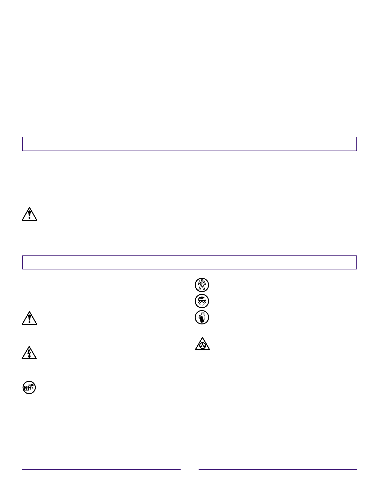
WARNING: Failure to observe may result in
personal injury, death, or equipment damage.
WARNING: Risk of electrical shock. Failure to
observe may result in personal injury or death.
S Always follow the instructions given in the operator’s
card and operating manual.
S Always follow instructions in the material supplier’s
Material Safety Data Sheet (MSDS) or material
information sheet.
S Even at recommended operating temperatures, hot
melt material may release vapors. Exceeding
prescribed processing temperatures for long periods of
time can result in dangerous decomposition
by-products. Remove vapors by drawing them off with
an exhaust system.
WARNING: Hot! Risk of burns. Wear
heat-protective clothing, safety goggles, and/or
heat-protective gloves depending on the symbol or
symbols shown.
WARNING: Pressurized system or material.
Release pressure. Failure to observe may result in
serious burns.
WARNING: Disconnect equipment from line
voltage.
Issued 9/94
1. Turn the motor OFF.
2. Trigger all guns or adhesive head.
3. Open the manifold drain valve.
1
O1EN–10–[35–37C3]–6
Page 2
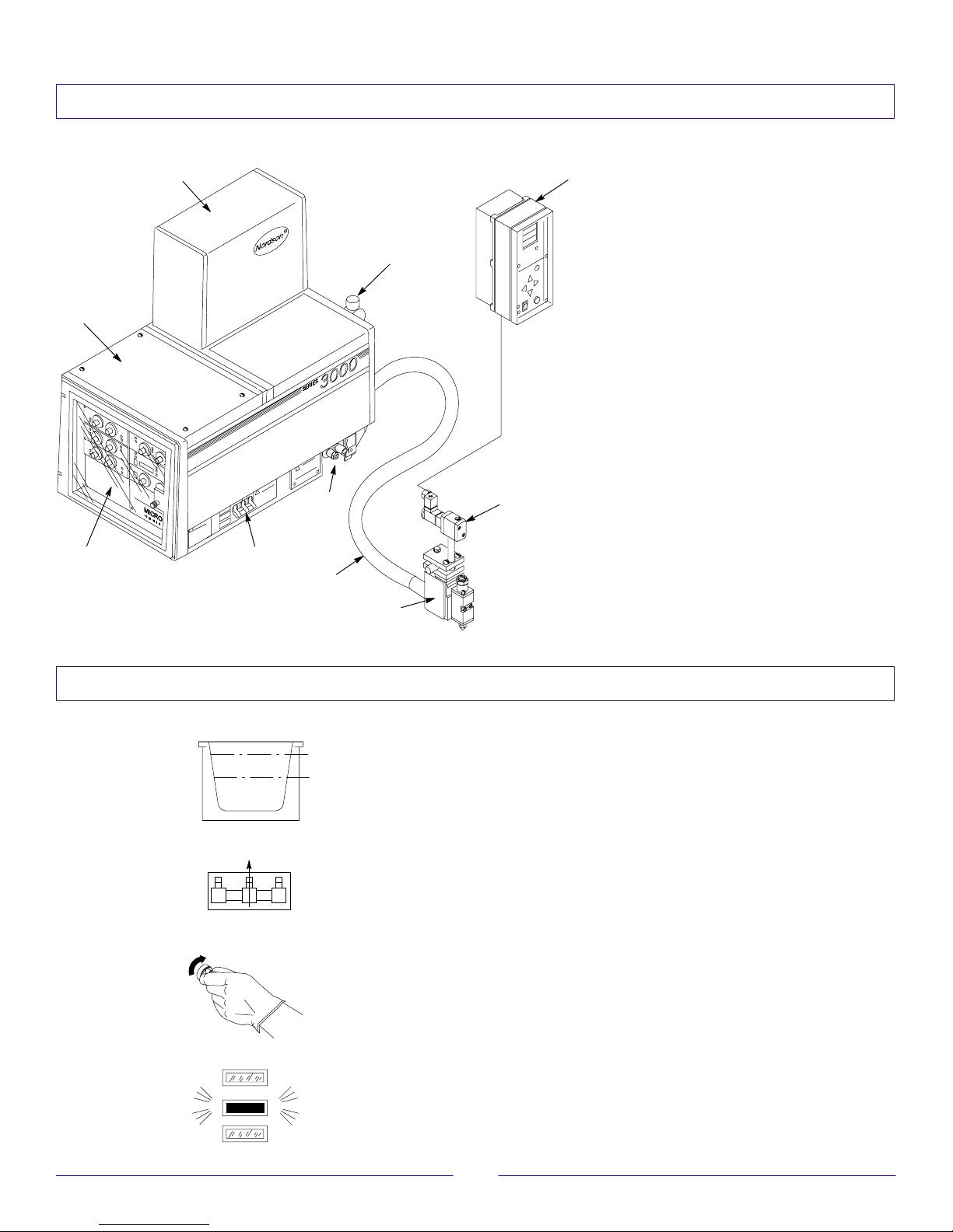
Overview of System Components
1
2
7
Applicator
1. Pump enclosure
6
2. Air regulator
3. Filter assembly
4. Circuit breaker
5. Controls
6. Electrical enclosure
Additional System Components
7. PC40 timer
3
8
8. Solenoid
9. H200 gun
5
4
10
9
10. Hose
Daily Startup/Shutdown
25 mm
50%
Startup
1. Check the adhesive level. Add adhesive to tank if
the level is below 50% of its holding capacity. Fill to
within 25 mm (1 inch) of tank top.
2. Close the lid immediately to prevent contamination
of the adhesive.
3. Set the circuit breaker to ON. Refer to “Overview of
System Components,” item 2.
4. Check the temperature settings for all zones
(channels).
5. Wait for “System Ready” indicator to become
illuminated.
O1EN–10–[35–37C3]–6
2
Issued 9/94
Page 3

Daily Startup/Shutdown
Startup (contd.)
6. Set the air pressure controls for the proper pump
and gun pressure.
7. Proceed with normal operation.
8. Check the adhesive level periodically. Refill the tank
before the level drops below 50% of its holding
capacity.
WARNING: When the tank lid is open, hot melt
vapors may be released.
Shutdown
1. Reduce the pump air pressure to “0.”
2. Trigger all guns to relieve trapped hydraulic
pressure.
3. Set the circuit breaker to OFF.
4. To prevent accidental gun triggering: a) Reduce
automatic gun air pressure to “0” or; b) Place the
trigger safety on manual guns to the locked position.
WARNING: Never hang a handgun by its trigger.
The gun can accidentally discharge material,
resulting in burns.
Daily Maintenance
1. Clean the exterior surfaces of the applicator and
guns.
2. Check the o-rings and gaskets for leaks.
3. Flush the manifold filter.
a. Reduce the pump air pressure to “0.”
b. Trigger all guns to relieve trapped hydraulic
pressure.
c. Turn the filter assembly center screw to DRAIN
(CW).
d. Open the left side drain valve over a container
(CCW).
e. Increase the pump air pressure until a clean
steady flow of hot melt material flows from the
drain.
f. Close the drain valve.
g. Reduce the pump air pressure to “0” and repeat
the procedure for the right side drain valve.
Issued 9/94
3
O1EN–10–[35–37C3]–6
Page 4
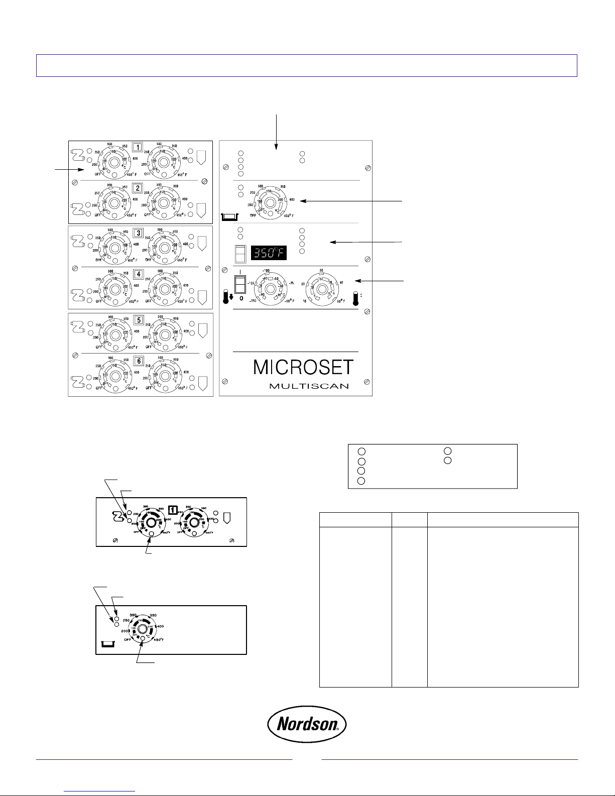
MultiScan Controller
1
CONTROL ON
SYSTEM READY
STEP
HOLD
SCAN
REMOTE SHUTDOWN
SETBACK ON
OPEN SENSOR
SHORTED SENSOR
5
Temperature Controls and Setting
NOTE: Temperature dials for channels that are not used
must be in the OFF position.
Channel fault LED (red)
Channel power on LED (yellow)
SYSTEM FAULT
TEMP. WARNING
OVERTEMPERATURE
HIGH
OK
LOW
System Status Indicators
CONTROL ON
SYSTEM READY
REMOTE SHUTDOWN
SETBACK ON
1. System status indicators
2. Tank temperature control
3. Channel status
2
indicators (standard) and
digital temperature
display (optional)
3
4. Temperature setback
control and High/low
monitor band (optional)
4
5. Hose and gun
temperature controls
SYSTEM FAULT
TEMP. WARNING
Channel scan LED (green)
Channel fault LED (red)
Channel power on LED (yellow)
Channel scan LED (green)
O1EN–10–[35–37C3]–6
LED Indicator Color Status with LED indicator on
CONTROL ON Green Input electrical power is on.
SYSTEM READY Green All channels are at their setpoint temper-
ature. System is ready.
REMOTE SHUT
DOWN
Yellow Only with I/O board option. All channel
heaters are off and pump is disabled.
SETBACK ON Yellow Temperature setback is on for all chan-
nels.
SYSTEM FAULT Red A fault condition exists. Channel fault or
channel status indicators for one or more
channels are on.
TEMPERATURE
WARNING
Yellow Temperature of a channel is outside the
limits set at the High/low temperature
monitor dial.
4
Issued 9/94
 Loading...