

Page 1
EN
Free Standing Cooker / User Manual
DE
Standherd / Gebrauchsanweisung
CSG63LPGWH
Page 2
Thank you for choosing this product.
This User Manual contains important safety information and instructions on the operation
and maintenance of your appliance.
Please take the time to read this User Manual before using your appliance and keep this
book for future reference.
Icon Type Meaning
WARNING Serious injury or death risk
RISK OF ELECTRIC SHOCK Dangerous voltage risk
FIRE Warning; Risk of re / ammable materials
CAUTION Injury or property damage risk
IMPORTANT / NOTE Operating the system correctly
EN - 2
Page 3

CONTENTS
1.SAFETY INSTRUCTIONS .................................................................................................4
1.1 General Safety Warnings ...............................................................................................4
1.2 Installation Warnings ......................................................................................................7
1.3 During Use .....................................................................................................................8
1.4 During Cleaning and Maintenance ...............................................................................10
2.INSTALLATION AND PREPARATION FOR USE ............................................................ 12
2.1 Instructions for the Installer ..........................................................................................12
2.2 Installation of the Cooker .............................................................................................. 13
2.3 Gas Connection ............................................................................................................ 13
2.4 Gas Conversion (if available) .......................................................................................14
2.5 Electrical Connection and Safety (if available) .............................................................16
2.6 Anti-tilting kit .................................................................................................................17
2.7 Adjusting the feet .......................................................................................................... 17
3.PRODUCT FEATURES ...................................................................................................18
4.USE OF PRODUCT ........................................................................................................19
4.1 Use of Gas Burners ......................................................................................................19
4.2 Hob Controls.................................................................................................................19
4.3 Use of the Mechanical Minute Minder Timer ................................................................22
4.4 Accessories ..................................................................................................................22
5.CLEANING AND MAINTENANCE...................................................................................23
5.1 Cleaning ...................................................................................................................23
5.2 Maintenance .................................................................................................................25
5.3 Maintenance .................................................................................................................26
6.TROUBLESHOOTING&TRANSPORT ............................................................................ 27
6.1 Troubleshooting ............................................................................................................ 27
6.2 Transport ...................................................................................................................28
7.TECHNICAL SPECIFICATIONS ......................................................................................29
7.1 Injector Table ................................................................................................................29
7.2 Energy Fiche ................................................................................................................30
7.3 Energy Fiche ................................................................................................................31
EN - 3
Page 4
1. SAFETY INSTRUCTIONS
• Carefully read all instructions before using your
appliance and keep them in a convenient place for
reference when necessary.
• This manual has been prepared for more than one
model therefore your appliance may not have some
of the features described within. For this reason, it
is important to pay particular attention to any figures
whilst reading the operating manual.
1.1 General Safety Warnings
• This appliance can be used by children aged from
8 years and above and by persons with reduced
physical, sensory or mental capabilities or lack
of experience and knowledge if they have been
given supervision or instruction concerning use of
the appliance in a safe way and understand the
hazards involved. Children should not play with the
appliance. Cleaning and user maintenance should
not be made by children without supervision.
WARNING: The appliance and its accessible parts
become hot during use. Care should be taken to avoid
touching heating elements. Keep children less than 8
years of age away unless they are continually
supervised.
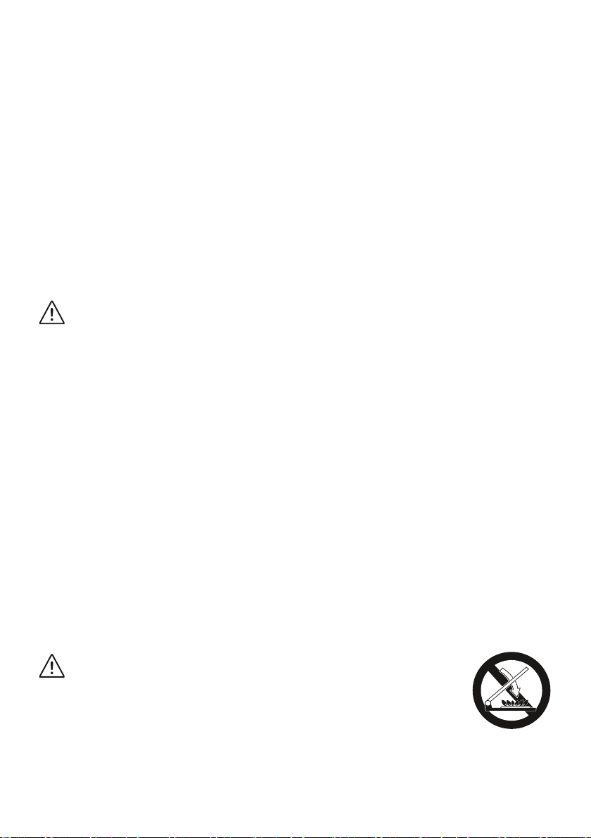
WARNING: Unattended cooking on a hob with
fat or oil can be dangerous and may result in fire.
NEVER try to extinguish such a fire with water, but
switch off the appliance and cover the flame with a lid
or a fire blanket.
CAUTION: The cooking process has to be
supervised. A short term cooking process has to be
supervised continuously
EN - 4
Page 5
WARNING: Danger of fire: Do not store items
on the cooking surfaces.
WARNING: If the surface is cracked, switch off
the appliance to avoid the possibility of electric shock.
• For models which incorporate a hob lid, clean any
spillages off the lid before use and allow the cooker
to cool before closing the lid.
• Do not operate the appliance with an external timer
or separate remote-control system.
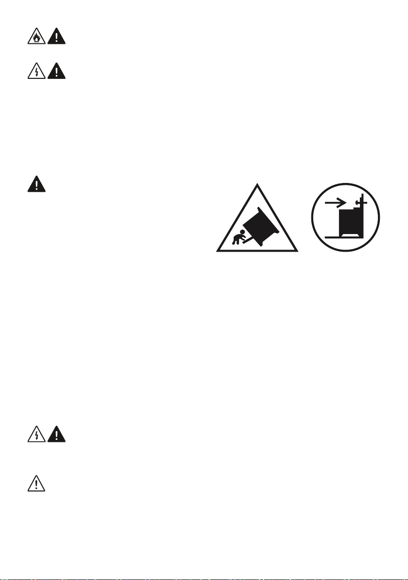
WARNING: To prevent
the appliance tipping, the
stabilising brackets must be
installed. (For detailed
information refer to the antitilting kit set guide.)
• During use the appliance will get hot. Care should
be taken to avoid touching heating elements inside
the oven.
• Handles may become hot after a short period during
use.
• Do not use harsh abrasive cleaners or scourers to
clean oven surfaces. They can scratch the surfaces
which may result in shattering of the door glass or
damage to surfaces.
• Do not use steam cleaners to clean the appliance.
WARNING: To avoid the possibility of electric
shock, make sure that the appliance is switched off
before replacing the lamp.
CAUTION: Accessible parts may be hot when
cooking or grilling. Keep young children away from the
appliance when it is in use.
• Your appliance is produced in accordance with all
EN - 5
Page 6
applicable local and international standards and
regulations.
• Maintenance and repair work should only be carried
out by authorised service technicians. Installation
and repair work that is carried out by unauthorised
technicians may be dangerous. Do not alter or
modify the specifications of the appliance in any
way. Inappropriate hob guards can cause accidents.
• Before connecting your appliance, make sure
that the local distribution conditions (nature of the
gas and gas pressure or electricity voltage and
frequency) and the specifications of the appliance
are compatible. The specifications for this appliance
are stated on the label.
CAUTION: This appliance is designed only for
cooking food and is intended for indoor domestic
household use only. It should not be used for any
other purpose or in any other application, such as for
non-domestic use, in a commercial environment or for
heating a room.
• Do not use the oven door handles to lift or move the
appliance.
• This appliance is not connected to a ventilation
device. It should be installed and connected in
accordance with current installation regulations.
Particular attention shall be given to the relevant
requirements regarding ventilation.
• If the burner has not lit after 15 seconds, stop
operating the device and open the compartment
door. Wait at least 1 minute before attempting to
ignite the burner again.
• These instructions are only valid if the correct
country symbol appears on the appliance. If the
symbol does not appear on the appliance, refer to
EN - 6
Page 7
the technical instructions which describe how to
modify the appliance to match the conditions of use
of the country.
• All possible measures have been taken to ensure
your safety. Since the glass may break, care should
be taken while cleaning to avoid scratching. Avoid
hitting or knocking the glass with accessories.
• Make sure that the supply cord is not trapped or
damaged during installation. If the supply cord is
damaged, it must be replaced by the manufacturer,
its service agent or similarly qualified persons in
order to prevent a hazard.
• Do not let children climb on the oven door or sit on it
while it is open.
• If your appliance is provided with a cooking hotplate
made of glass or glass ceramic:
CAUTION: “In case of hotplate glass breakage”:
- immediately shut off all burners and any electrical
heating element and isolate the appliance from the
power supply
- do not touch the appliance surface
- do not use the appliance.
• Please keep children and animals away from this
appliance.
1.2 Installation Warnings
• Do not operate the appliance before it is fully
installed.
• The appliance must be installed by an authorised
technician. The manufacturer is not responsible
for any damage that might be caused by incorrect
placement and installation by unauthorised people.
• When the appliance is unpacked, make sure that
it is has not been damaged during transportation.
EN - 7
Page 8

In the case of a defect do not use the appliance
and contact a qualified service agent immediately.
The materials used for packaging (nylon, staplers,
styrofoam, etc.) may be harmful to children and they
should be collected and removed immediately.
• Protect your appliance from the atmosphere. Do
not expose it to sun, rain, snow, dust or excessive
humidity.
• Materials around the appliance (i.e. cabinets) must
be able to withstand a minimum temperature of
100°C.
1.3 During Use
• When you first use your oven you may notice a
slight smell. This is perfectly normal and is caused
by the insulation materials on the heater elements.
We suggest that, before using your oven for the
first time, you leave it empty and set it at maximum
temperature for 45 minutes. Make sure that the
environment in which the product is installed is well
ventilated.
• Take care when opening the oven door during or
after cooking. The hot steam from the oven may
cause burns.
• Do not put flammable or combustible materials in or
near the appliance when it is operating.
• Always use oven gloves to remove and replace food
in the oven.
Do not leave the cooker unattended when
cooking with solid or liquid oils. They may catch fire
under extreme heating conditions. Never pour water
on to flames that are caused by oil, instead switch the
cooker off and cover the pan with its lid or a fire
blanket.
EN - 8
Page 9
• Always position pans over the centre of the cooking
zone, and turn the handles to a safe position so they
cannot be knocked.
• If the product will not be used for a long period of
time, turn the main control switch off. Turn the gas
valve off when gas appliances are not in use.
• Make sure the appliance control knobs are always
in the “0” (stop) position when the appliance is not in
use.
• The trays incline when pulled out. Take care not
to spill or drop hot food when removing it from the
oven.
CAUTION: The use of a gas cooking appliance
results in the production of heat, moisture and
products of combustion in the room in which it is
installed. Ensure that the kitchen is well ventilated
especially when the appliance is in use, keep natural
ventilation holes open or install a mechanical
ventilation device (mechanical extractor hood).
• Prolonged intensive use of the appliance may call
for additional ventilation, such as opening a window,
or for more effective ventilation, for example by
increasing the level of mechanical ventilation where
present.
• While using the grill burner, keep the oven door
open and always use the grill deflector shield
supplied with the product. Never use the grill burner
with the oven door closed.
CAUTION: Glass lids may shatter when
heated. Turn off all the burners and allow the
hob surface to cool before closing the lid.
• Do not place anything on the oven door
when it is open. This could unbalance the oven or
damage the door.
EN - 9
Page 10

• Do not place heavy or flammable items (e.g. nylon,
plastic bags, paper, cloth, etc.) into the drawer. This
includes cookware with plastic accessories (e.g.
handles).
CAUTION: The inside surface of the storage
compartment may get hot when the appliance is in
use. Avoid touching the inside surface.
• Do not hang towels, dishcloths or clothes from the
appliance or its handles.
1.4 During Cleaning and Maintenance
• Make sure that your appliance is turned off at
the mains before carrying out any cleaning or
maintenance operations.
• Do not remove the control knobs to clean the control
panel.
• To maintain the efficiency and safety of your
appliance, we recommend you always use original
spare parts and to call our authorised service agents
when needed.
CE Declaration of conformity
We declare that our products meet the
applicable European Directives, Decisions
and Regulations and the requirements listed
in the standards referenced.
This appliance has been designed to be used only
for home cooking. Any other use (such as heating a
room) is improper and dangerous.
The operating instructions apply to several models.
You may notice differences between these instructions
and your model.
EN - 10
Page 11

Disposal of your old machine
This symbol on the product or on its packaging
indicates that this product should not be
treated as household waste. Instead it should
be handed over to the applicable collection
point for the recycling of electrical and
electronic equipment. By ensuring this product is
disposed of correctly, you will help prevent potential
negative consequences for the environment and
human health, which could otherwise be caused by
inappropriate waste handling of this product. For more
detailed information about recycling of this product,
please contact your local city office, your household
waste disposal service or the retailer who you
purchased this product from.
EN - 11
Page 12
2. INSTALLATION AND
PREPARATION FOR USE
WARNING : This appliance must be
installed by an authorised service
person or qualified technician,
according to the instructions in this guide
and in compliance with the current local
regulations.
• Incorrect installation may cause harm
and damage, for which the manufacturer
accepts no responsibility and the
warranty will not be valid.
• Prior to installation, ensure that the local
distribution conditions (electricity voltage
and frequency and/or nature of the gas
and gas pressure) and the adjustments
of the appliance are compatible. The
adjustment conditions for this appliance
are stated on the label.
• The laws, ordinances, directives and
standards in force in the country of use
are to be followed (safety regulations,
proper recycling in accordance with the
regulations, etc.).
Air inlet section
min. 100 cm
COOKER
Air inlet section
min. 100 cm
2
COOKER
Cooker
hood
flue
Air inlet section
min. 100 cm
2
2
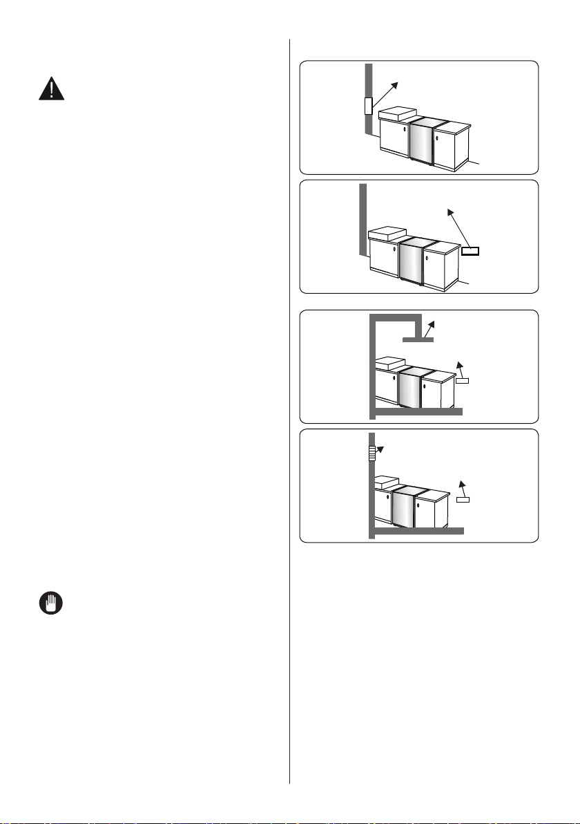
2.1 Instructions for the Installer
Ventilation requirements
• For rooms with a volume of less than
5 m3, permanent ventilation of 100 cm
2
free area is required.
• For rooms with a volume of between 5
m3 and 10 m3, permanent ventilation of
50 cm2 free area will be required, unless
the room has a door which opens
directly to outside air in which case no
permanent ventilation is required.
• For rooms with a volume greater than
10 m3, no permanent ventilation is
required.
Important: Regardless of room size,
all rooms containing the appliance
must have direct access to outside air
via an openable window or equivalent.
Emptying of burned gases from the
environment
Gas appliances expel burned gas waste
to the outside air, either directly or via a
cooker hood with a chimney. If it is not
possible to install a cooker hood, install a
fan on the window or wall that has access
to fresh air. The fan must have the capacity
to change the volume of air in the kitchen a
minimum of 4-5 times per hour.
COOKER
Electrical ventilator
Air inlet section
min. 100 cm
COOKER
2
General instructions
• After removing the packaging material
from the appliance and its accessories,
ensure that the appliance is not
damaged. If you suspect any damage,
do not use it and contact an authorised
service person or qualified technician
immediately.
• Make sure that there are no flammable
or combustible materials in the close
vicinity, such as curtains, oil, cloth etc.
which may catch fire.
• The worktop and furniture surrounding
the appliance must be made of
materials resistant to temperatures
above 100°C.
EN - 12
Page 13
• The appliance should not be installed
next to a dishwasher, fridge, freezer,
washing machine or clothes dryer.
• The appliance can be placed close to
other furniture on condition that in the
area where the appliance is set up, the
furniture’s height does not exceed the
height of the cooktop.
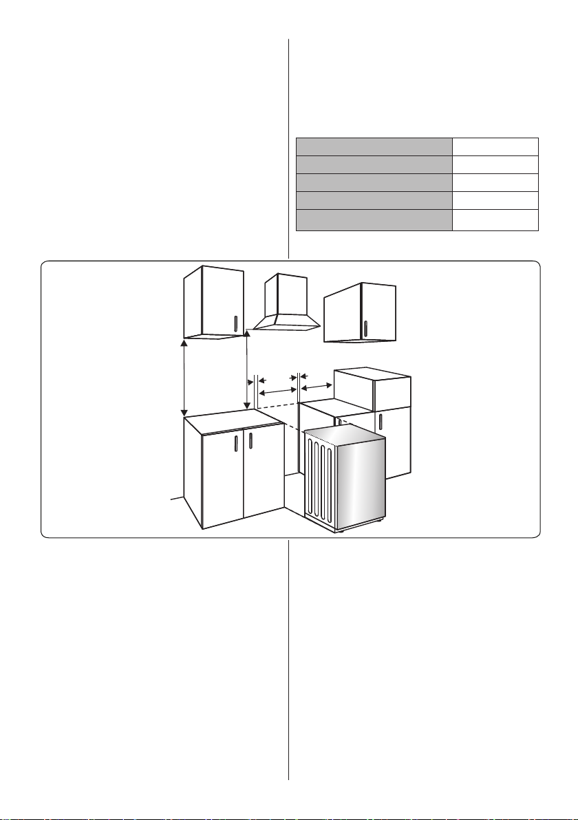
2.2 Installation of the Cooker
• If the kitchen furniture is higher than the
cooktop, the kitchen furniture must be
at least 10 cm away from the sides of
appliance for air circulation.
• There should be a minimum 2cm blank
space around the appliance for air
circulation.
• If a cooker hood or any cupboard is to
be installed above the appliance, the
safety distance between cooktop and
any cupboard/cooker hood should be as
shown below.
A (mm) 420
B (mm) Cooker Hood/Cupboard 650/700
C (mm) 20
D (mm) Product Width
E (mm) 100
A
B
C
2.3 Gas Connection
Assembly of gas supply and leakage
check
Connect the appliance in accordance
with applicable local and international
standards and regulations. First, check
what type of gas is installed on the cooker.
This information is available on a sticker
on the back of the cooker. You can find
the information related to appropriate gas
types and appropriate gas injectors in
the technical data table. Check that the
feeding gas pressure matches the values
on the technical data table, to be able to
get the most efficient use and to ensure the
minimum gas consumption. If the pressure
of used gas is different than the values
C
E
D
stated or is not stable in your area, it may
be necessary to assemble an available
pressure regulator on the gas inlet. You
should contact an authorised service centre
to make these adjustments.
Points that must be checked during
flexible hose assembly
• If the gas connection is made by a
flexible hose fixed onto the gas inlet of
the hob, it must be fixed on by a pipe
collar.
• Connect your appliance with a short
and durable hose that is as close as
possible to the gas source.
• The permitted maximum length of the
hose is 1.5 m.
EN - 13
Page 14
• The device should be connected in line
with the relevant local gas standards.
• The hose must be kept clear of areas
that may heat up to temperatures of
more than 90°C.
• The hose must not be cracked, torn,
bent or folded.
• Keep the hose clear of sharp corners
and objects that could move.
• Before you assemble the connection,
you must make sure the hose is not
damaged. Use bubbly water or leakage
fluids to perform the check. Do not use
a naked flame to check for gas leakage.
• All metal items that are used during
gas connection must be free from
rust. Check the expiry date of any
components used for connection.
Points that must be checked during
fixed gas connection assembly
The method used to assemble a fixed
gas connection (gas connection made by
threads, e.g. a nut) varies according to the
country you are in. The most common parts
for your country will be supplied with your
appliance. Any other parts required can be
supplied as spare parts.
During connection, always keep the nut
on the gas manifold fixed while rotating
the counter-part. Use appropriately-sized
spanners for a safe connection. For
surfaces between different components
always use the seals provided in the gas
conversion kit.
The seals used during connection should
also be approved to be used in gas
connections. Do not use plumbing seals for
gas connections.
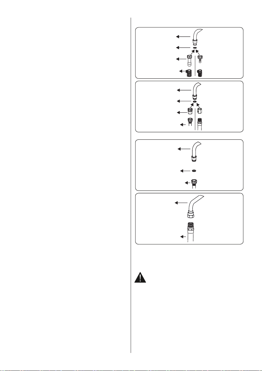
Remember that this appliance is ready
to be connected to the gas supply in the
country for which it has been produced.
The main country of destination is marked
on the rear cover of the appliance. If you
need to use it in another country, any
of the connections in the figure below
may be required. In such a case, contact
local authorities to learn the correct gas
connection.
Gas pipe
Seal
Hose
fitting
Gas hose
with collar
Gas pipe
Seal
Adapter
Mechanical
gas hose
Gas pipe
Seal
Mechanical
gas hose
Gas
pipe
Mechanical
gas hose
The Cooker must be installed and
maintained by a suitably qualified gas
registered technician in accordance with
current safety legislation.
WARNING: Do not use a naked flame
to check for gas leaks.
2.4 Gas Conversion (if available)
Your appliance is designed to be operated
with LPG/NG gas. The gas burners can
be adapted to different types of gas, by
replacing the corresponding injectors and
adjusting the minimum flame length suitable
to the gas in use. For this purpose, the following steps should be performed.
Changing injectors
Hob burners
EN - 14
Page 15
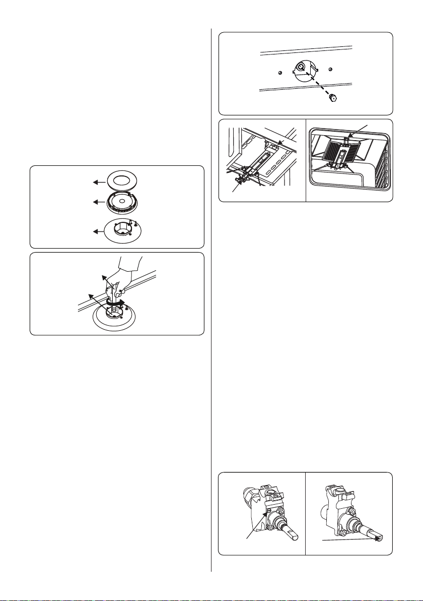
• Cut off the main gas supply and unplug
the appliance from the mains electrical
supply.
• Remove the burner caps and the
adapters.
• Use a 7 mm spanner to unscrew the
injectors.
• Replace the injector with the ones from
the gas conversion kit, with the correct
diameters for the type of gas that is
going to be used, according to the gas
injector table.
Burner
cap
Adapter
Cup
Spanner
Adapter
Oven/Grill (if available) Injectors
The oven and grill injectors are held in
position by a single screw on the tip of the
burner.
For oven burners, open the drawer
compartment and locate the assembly
screw below the burner. Remove the screw,
move the burner diagonally and the injector
will be revealed on the rear side of the
burner box.
For grill burners, the screw is already
visible. Remove the screw, pull the grill
burner towards you and the injector will
be visible on the rear surface of the oven
cavity.
Oven burner
Screw
Injector
Remove the injectors using a 7mm
spanner and replace the injector with the
ones from the spare set. Make sure you
use corresponding diameters suitable to
the type of gas that is going to be used,
according to the information chart (which is
also supplied in the gas conversion kit).
Adjusting the minimum flame position
First of all, make sure that the appliance
is unplugged from the mains electrical
supply and that the gas feed is open.
The minimum flame position is adjusted
with a flat screw located on the valve. As
shown in the figures below; for valves with
a flame failure safety device, the screw is
located on the side of the valve spindle
and for valves without a flame failure
safety device, the screw is located inside
the valve spindle. To make adjusting the
flame position easier, we recommend that
you remove the control panel (and the
micro switch if your model has one) during
the alteration. The bypass screw must
be loosened for conversion from LPG to
natural gas. For conversion from natural
gas to LPG, the bypass screw must be
tightened.
Valve with flame failure
device
Valve without flame
failure device
EN - 15
Bypass screw
Screw(inside the hole)
Page 16
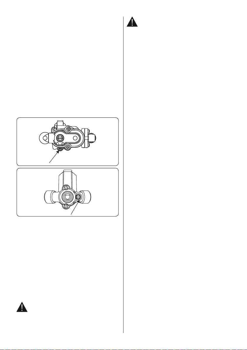
Determining the minimum flame position
To determine the minimum position, ignite
the burners and leave them on in the
minimum position. Remove the knobs to
gain access to the screws. With the help
of a small screwdriver, fasten or loosen the
bypass screw by around 90 degrees. When
the flame has a length of at least 4mm,
the gas is well distributed. Make sure that
the flame does not die out when passing
from the maximum position to the minimum
position. Create an artificial wind with your
hand towards the flame to see if the flames
are stable. For the oven burner, operate the
oven burner at the minimum position for 5
minutes, then open and close the oven door
2-3 times to check the flame stability of the
burner.
Thermostatic oven valve
Bypass screw
Non-thermostatic
oven valve
Bypass screw
Changing the gas inlet
For some countries, the gas inlet type
can be different for NG/LPG gases. In
this case, remove the current connection
components and nuts (if any) and connect
the new gas supply accordingly. In all
conditions, all components used in gas
connections should be approved by local
and/or international authorities. In all gas
connections, refer to the “Assembly of
gas supply and leakage check” clause
explained above.
2.5 Electrical Connection
and Safety (if available)
WARNING: The electrical connection
of this appliance should be carried out
by an authorised service person or
qualified electrician, according to the
instructions in this guide and in compliance
with the current local regulations.
WARNING: THE APPLIANCE MUST
BE EARTHED.
• Before connecting the appliance to the
power supply, the voltage rating of the
appliance (stamped on the appliance
identification plate) must be checked for
correspondence to the available mains
supply voltage, and the mains electric
wiring should be capable of handling the
appliance’s power rating (also indicated
on the identification plate).
• During installation, please ensure
that isolated cables are used. An
incorrect connection could damage
your appliance. If the mains cable is
damaged and needs to be replaced this
should be done by a qualified person.
• Do not use adaptors, multiple sockets
and/or extension leads.
• The supply cord should be kept away
from hot parts of the appliance and must
not be bent or compressed. Otherwise
the cord may be damaged, causing a
short circuit.
• If the appliance is not connected
to the mains with a plug, a all-pole
disconnector (with at least 3 mm contact
spacing) must be used in order to meet
the safety regulations.
• The appliance is designed for a power
supply of 220-240 V~. If your supply is
different, contact the authorized service
personnel or qualified electrician.
• The power cable (H05VV-F) must be
long enough to be connected to the
appliance.
• The fused switch must be easily
accessible once the appliance has been
installed.
• Ensure all connections are adequately
tightened.
• Fix the supply cable in the cable clamp
and then close the cover.
• The terminal box connection is placed
on the terminal box.
EN - 16
Page 17
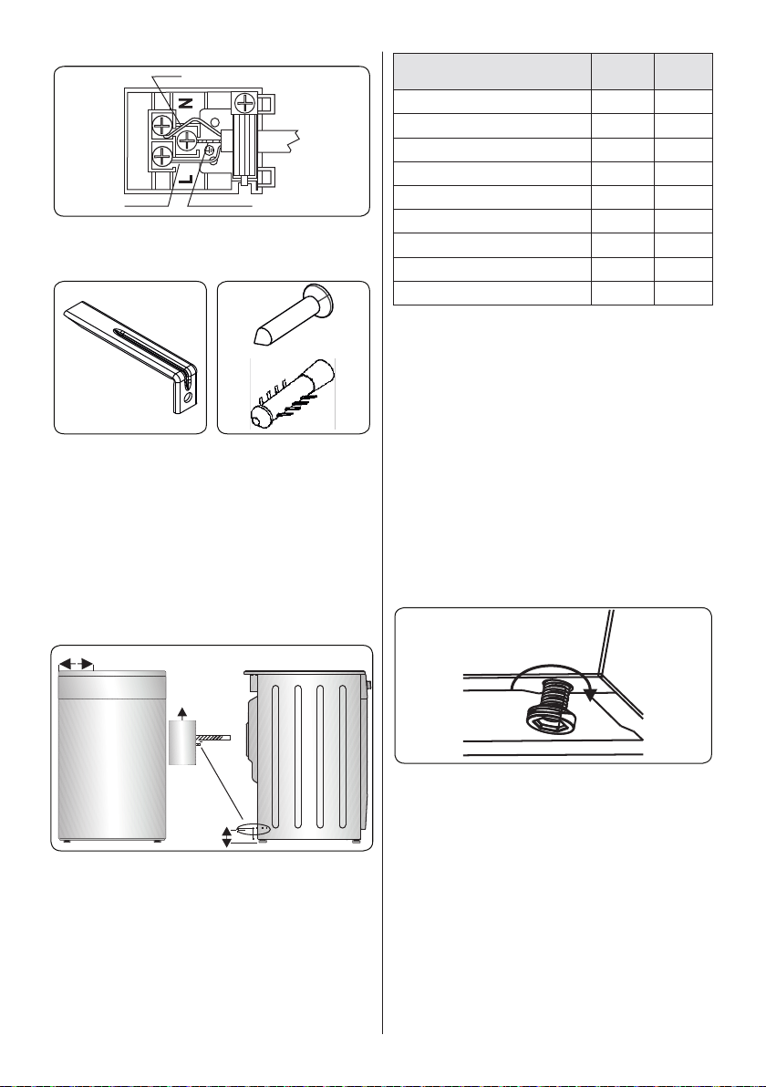
Blue
Brown
2.6 Anti-tilting kit
1 2
Yellow+Green
Product Dimensions
(Width X Depth X Height) (Cm)
60x60x90 (Double Oven) 297.5 52
50x60x90 (Double Oven) 247.5 52
90x60x85 430 107
60x60x90 309.5 112
60x60x85 309.5 64
50x60x90 247.5 112
50x60x85 247.5 64
50x50x90 247.5 112
50x50x85 247.5 64
A (mm) B (mm)
Screw (x1)
Anti-tilting
Bracket
(x1) (will be
attached to the
wall)
3
wall
plug (x1)
The document bag contains an
anti-tilting kit. Loosely attach the antitilting bracket (1) to the wall using the
screw (2) and wall plug (3), following the
measurements shown in the figure and
table below. Adjust the height of the antitilting bracket so that it lines up with the slot
on the cooker and tighten the screw. Push
the appliance towards the wall making sure
that the anti-tilting bracket is inserted into
the slot on the rear of the appliance.
A
Wall
Antitilting
bracket
B
2.7 Adjusting the feet
Your product stands on four adjustable
feet. For safe operation, it is important that
your appliance is correctly balanced. Make
sure the appliance is level prior to cooking.
To increase the height of the appliance,
turn the feet anti-clockwise. To decrease
the height of the appliance, turn the feet
clockwise.
It is possible to raise the height of the
appliance up to 30 mm by adjusting the
feet. The appliance is heavy and we
recommend that a minimum of 2 people lift
it. Never drag the appliance.
EN - 17
Page 18
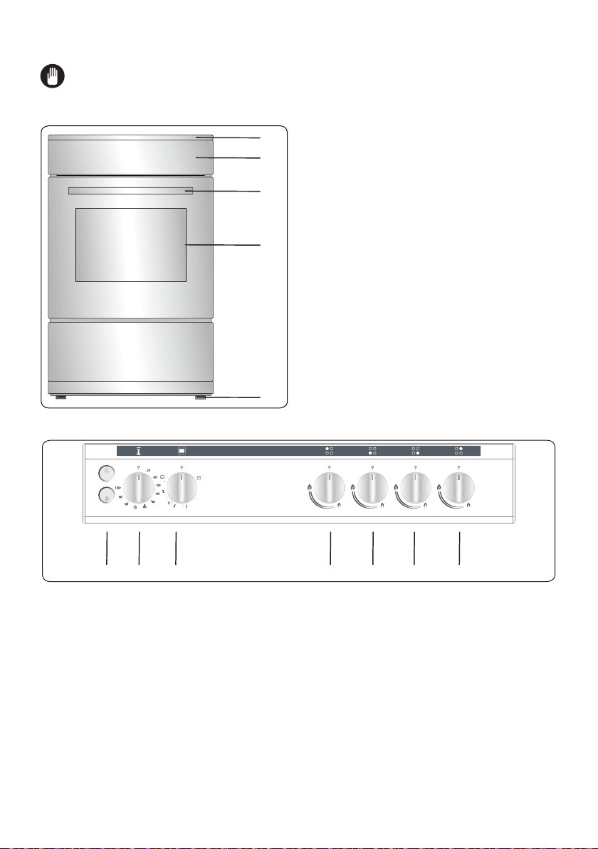
3. PRODUCT FEATURES
Important: Specifications for the product vary and the appearance of your appliance
may differ from that shown in the figures below.
List of Components
1. Cooktop
1
2. Control Panel
2
3. Oven Door Handle
4. Oven Door
3
5. Adjustable Feet
4
5
Control Panel
Min
Max
6
8
7
6. Button (Ignition/Oven Lamp/Turnspit/Fan)
7. Timer
8. Oven Control Knob
9. Oven Burner Control Knob
EN - 18
9
9
9
9
Page 19
4. USE OF PRODUCT
4.1 Use of Gas Burners
Ignition of the Burners
The position symbol above each control
knob indicates the burner that the knob
controls.
Manual ignition of the gas burners
If your appliance is not equipped with an
ignition aid, or in case there is a failure in
the electric network, follow the procedures
listed below.
For hob burners: Push in the knob of
the burner you wish to ignite and keep
it pressed while turning it anti-clockwise
until the knob is in the ‘maximum’ position.
Continue pressing the knob and hold a lit
match, taper or other manual aid to the
upper circumference of the burner. Move
the ignition source away from the burner as
soon as you see a stable flame.
For oven burner: Push in and turn the
oven control knob anti-clockwise until the
knob is in the ‘maximum’ position. Hold a
lit match, taper or other manual aid to to
the ignition hole that is located on the front
left corner of the burner. Move the ignition
source away as soon as you see a stable
flame.
For grill burner: Push in and turn the grill
control knob clockwise until the marker on
the knob points at the grill sign. Continue
pressing the knob and hold a lit match,
taper or other manual aid to the holes on
the burner. Move the ignition source away
from the burner as soon as you see a stable
flame.
Electrical ignition by spark button
Push in the knob of the burner you wish
to ignite and keep it pressed while turning
it anti-clockwise until the knob is in the
'maximum' position. While keeping the
knob pressed in, push the ignition button.
Make sure that you press the ignition button
immediately as a delay could cause a build
up of gas which may result in the flame
spreading. Continue pressing the ignition
button until you see a stable flame on the
burner.
Flame safety device
Hob burners
Hobs equipped with a flame failure device
provide security in case of an accidentally
extinguished flame. If such a case occurs,
the device will block the burners gas
lines and will avoid any accumulation of
unburned gas. Wait 90 seconds before reigniting an extinguished gas burner.
Oven / Grill (If available) Burners
Regardless of the model of your appliance,
all oven burners are equipped with a gas
safety device. For this reason, during
ignition, keep the oven knob pressed until
you see stable flames. If the flames are cut
out after you release the knob, repeat the
ignition procedure. If the oven burner does
not ignite after you keep the burner knob
pressed for 30 seconds, open the oven
door and do not attempt re-ignition for at
least 90 seconds. If the oven flames go out
accidentally, repeat the same procedure.
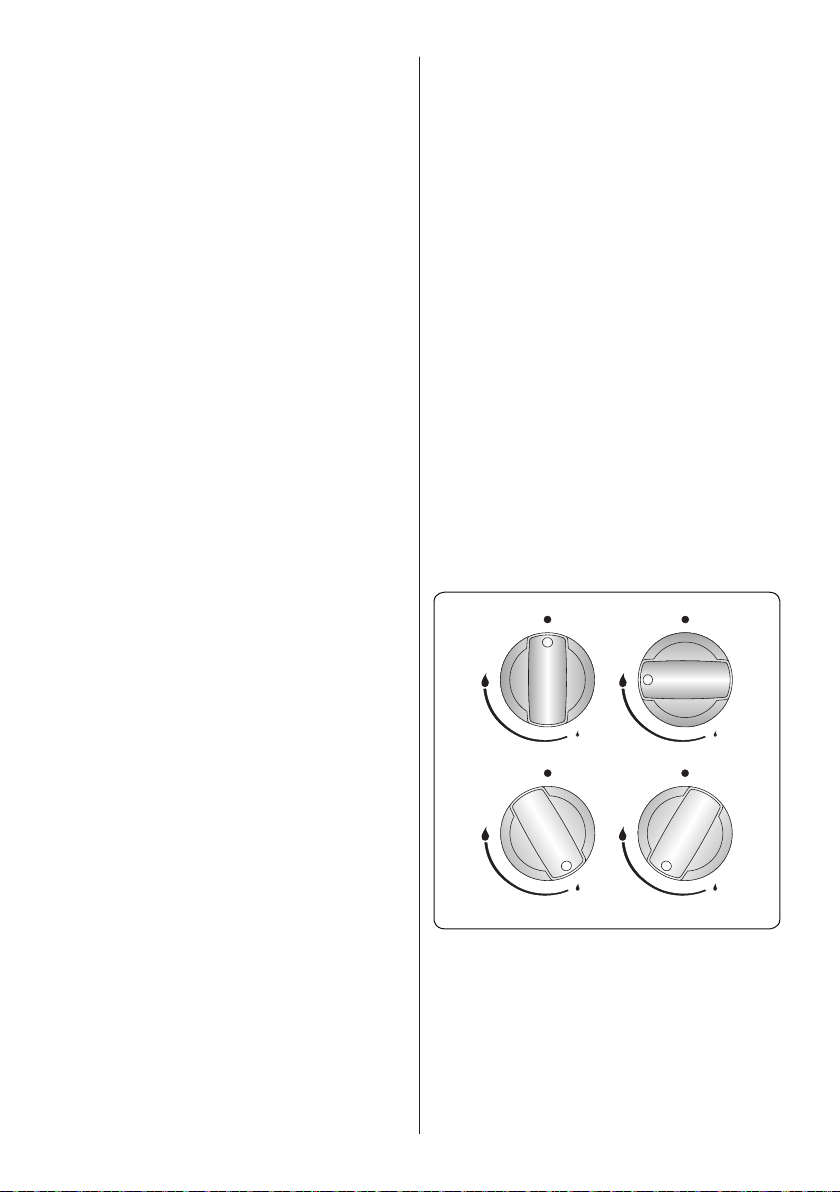
4.2 Hob Controls
Hob burner
The knob has 3 positions: off (0), maximum
(big flame symbol) and minimum (small
flame symbol). Ignite the burner with the
knob in the 'maximum' position; you can
then adjust the flame length between the
'maximum' and 'minimum' positions. Do
not operate the burners when the knob is
between the 'maximum' and 'off' positions.
OFF position
MIN. position MODULATE
MAX position
After ignition, visually check the flames.
If you see a yellow tip, lifted or unstable
flame, switch the gas flow off, then check
the assembly of burner caps and crowns
once they have cooled. Make sure there is
no liquid in the burner caps. If the burner
flames go out accidentally, switch the
burners off, ventilate the kitchen with fresh
air and wait at least 90 seconds before
attempting re-ignition.
EN - 19
Page 20

Cap
Crown
Spark
plug
Burner
cup
To switch the hob burners off, turn the hob
burner knob clockwise to the ‘0’ position or
so that the marker on the hob burner knob
points upwards.
Your hob has burners of different diameters.
You will find that the most economical
way of using gas is to choose the correct
size gas burner for your cooking pan size
and to bring the flame to the 'minimum'
position once boiling point is reached. We
recommend that you always cover your
cooking pan to avoid heat loss.
To obtain maximum performance from the
main burners, we suggest you use pots with
the following flat bottom diameters. Using
pots smaller than the minimum dimensions
shown below will cause energy loss.
Rapid / Wok Burner 22-26 cm
Semi-rapid Burner 14-22 cm
Auxiliary Burner 12-18 cm
Make sure that the tips of the flames do not
spread out from the outer circumference
of the pan, as this may harm plastic
accessories, such as handles.
Switch the main gas control valve off when
the burners are not in use for prolonged
periods of time.
WARNING:
• Only use flat-bottomed pans with thick
bases.
• Make sure the bottom of the pan is dry
before placing it on the burner.
• The temperature of accessible parts
may become high while the appliance is
operating. It is imperative that children
and animals are kept well away from the
burners during and after cooking.
• After use, the hob remains very hot for a
prolonged period of time. Do not touch it
and do not place any object on top of it.
• Never place knives, forks, spoons and
lids on the hob as they will get hot and
could cause serious burns.
• Do not allow pan handles or any other
cooking utensils to project over the edge
of the cooker top.
Circular Saucepan
Base
Small Saucepan
Diameter
Saucepan base that
has not settled
Oven Controls
Oven Burner Controls
After you ignite the oven burner, you can
adjust the temperature inside the oven, as
required, using the numbers on the control
panel or knob. The higher numbers provide
higher temperatures, while smaller numbers
provide lower temperatures.
Function Description
Min. 1...9/1...7
Max.
Turn the control anti-clockwise to
set to the Gas Mark as required.
Do not operate the appliance between
the “Off” position and the first temperature
marker in the anti-clockwise direction.
Always use the oven between the maximum
and minimum settings. When switching
the oven off, turn the knob in the clockwise
direction to the “0” position.
Preheating
When you need to preheat the oven, we
recommend you do so for 10 minutes.
For recipes needing high temperatures,
e.g. bread, pastries, scones, soufflés
etc., best results are achieved if the oven
is preheated first. For best results when
cooking frozen or cooked chilled ready
meals always preheat the oven first.
EN - 20
Page 21

Product Dimensions
(Width*Depth)
90*60
Position Temperature(°C)
MAX 280
9 240
8 230
7 220
6 200
5 190
4 180
3 170
2 150
1 140
• When cooking more than one dish in
the oven, place the dishes centrally
on different shelves rather than cluster
several dishes on one shelf, this will
allow the heat to circulate freely for the
best cooking results.
• If you are cooking more than one tray
of similar items, for example cakes or
biscuits, swap the trays during cooking
or remove the top tray when the food on
it is cooked and move the lower tray to
the higher shelf to finish cooking.
• Do not place baking trays directly on
the oven base as it interferes with the
oven air circulation and can lead to base
burning. Use the lower shelf position.
Product Dimensions(Width*Depth)
60*60/90*60
BC
Position
Temperature
(°C)
MAX 270 270 250
7 240 - 230
. 230 250 220
5 200 240 210
. 190 220 200
3 180 200 190
. 170 190 180
1 150 180 170
MIN 145 160 155
50*60 50*50
Temperature
(°C)
Temperature
(°C)
Cooking
• Ensure that food is placed centrally
on the shelf and that there is sufficient
room around the baking tray / dish to
allow for maximum circulation.
• Stand dishes on a suitably sized baking
tray on the shelf to prevent spillage onto
the oven base and to help reduce the
amount of cleaning required.
• The material and finish of the baking
tray and dishes used will affect base
browning. Enamel, dark, heavy or
nonstick utensils increase base
browning. Shiny aluminium or polished
steel trays reflect the heat away and
reduce base browning.
Grill Burner Controls
Function Description
Turn the control clockwise to set
the Grill.
CAUTION: Accessible parts may
become hot while the grill is in use.
Young children should be kept away. As
soon as you ignite the burner, place the grill
heat shield under the control panel. Then,
lift the oven door up slowly until it stops at
the semi-open position (approximately 30°)
and touches the heat shield.
Assembling the grill heat shield
Hold the heat shield with the warnings
facing upwards. There are two small slots
EN - 21
Page 22

on the right and left side of the rear edge of
the shield, as shown in the figure.
There are two screws equipped with bushes
under the oven control panel. Align the
bushes with the assembly slots so that the
shield is located between the control panel
and the bush. Push the shield towards the
appliance until it is firmly in its place.
Cooking
• The grill burner creates a source of
heat at a constant rate and cannot be
adjusted between the maximum and
minimum positions. When switching
the grill burner off, turn the knob in a
clockwise direction to the “0” position.
• Place a tray on the shelf below the grid
in order to collect the fat during grilling.
• Place the wire grid on the topmost shelf,
provided that the food does not touch
the grill burner.
• Preheat the grill on a full setting for a
few minutes before sealing steaks or
toasting. Food should be turned, as
required, during cooking.
• Food should be thoroughly dried before
grilling to minimize splashing. Brush
lean meats and fish lightly with a little
oil or melted butter to keep them moist
during cooking.
• Food should be placed in the centre of
the grid to allow for maximum circulation
of air.
• Never cover the grill pan or grid with foil
as this can lead to grill fires.
• If your appliance has a grill pan and
handle set as an accessory, refer to the
accessories section for its usage.
Turn the Timer knob clockwise to set the
desired cooking time. When the timer
reaches zero, an audible warning will
sound. The oven will remain switched on
until the oven control is switched off.
4.4 Accessories
The Deep Tray
The deep tray is best used for cooking
stews.
Put the tray into any rack and push it to the
end to make sure it is placed correctly.
The Grill Heat Shield
WARNING
When the grill is in use for longer
than 15 minutes, always fit the heat shield
provided to prevent the control knobs from
overheating. Take care to avoid touching
the heat shield when closing the oven
door. Allow the heat shield to cool before
removing.
WARNING: Ensure that the grill is
switched off before closing the door.
Oven Lamp
There is an oven lamp inside the oven to
illuminate the cooking area. Press the lamp
button to switch the lamp on or off.
4.3 Use of the Mechanical Minute Minder
Timer
Function Description
0..........100
Operating by adjusting the
timer
EN - 22
Page 23

WARNING
Place the grid to any corresponding
rack in the oven cavity correctly and push it
to the end.
5. CLEANING AND
MAINTENANCE
The Grill Pan and Handle Set
The grill pan set is best used for grilling
steaks and similar foods.
WARNING: The grill pan has a
detachable handle. Make sure when
using the grill pan handle that it is
centralised and secure, as shown in the
figure. Do not leave the handle in position
while grilling is in operation.
The Wire Grid
The wire grid is best used for grilling or for
processing food in oven-friendly containers.
EN - 23
5.1 Cleaning
WARNING: Switch off the appliance
and allow it to cool before cleaning is
to be carried out.
General Instructions
• Check whether the cleaning materials
are appropriate and recommended by
the manufacturer before use on your
appliance.
• Use cream cleaners or liquid cleaners
which do not contain particles. Do not
use caustic (corrosive) creams, abrasive
cleaning powders, rough wire wool or
hard tools as they may damage the
cooker surfaces.
Do not use cleaners that contain
particles, as they may scratch the
glass, enamelled and/or painted parts
of your appliance.
• Should any liquids overflow, clean them
immediately to avoid parts becoming
damaged.
Do not use steam cleaners for
cleaning any part of the appliance.
Page 24

Cleaning the Inside of the Oven
• The inside of enamelled ovens are best
cleaned while the oven is warm.
• Wipe the oven with a soft cloth soaked
in soapy water after each use. Then,
wipe the oven over again with a wet
cloth and dry it.
• You may need to use a liquid cleaning
material occasionally to completely
clean the oven.
Cleaning the Gas Hob
• Clean the gas hob on a regular basis.
• Take off the pan supports, caps and
crowns of the hob burners.
• Wipe the hob surface with a soft cloth
soaked in soapy water. Then, wipe the
hob surface over again with a wet cloth
and dry it.
• Wash and rinse the hob-burner caps.
Do not leave them wet. Dry them
immediately with a dry cloth.
• Make sure you re-assemble all parts
correctly after cleaning.
• The surfaces of the pan supports may
become scratched over time due to use.
This is not a production fault.
Do not use a metal sponge for
cleaning any part of the hob.
Make sure no water gets into the
burners as this may block the injectors.
Cleaning the Glass Parts
• Clean the glass parts of your appliance
on a regular basis.
• Use a glass cleaner to clean the inside
and outside of the glass parts. Then,
rinse and dry them thoroughly with a dry
cloth.
Cleaning the Enamelled Parts
• Clean the enamelled parts of your
appliance on a regular basis.
• Wipe the enamelled parts with a soft
cloth soaked in soapy water. Then, wipe
them over again with a wet cloth and dry
them.
Do not clean the enamelled parts while
they are still hot from cooking.
Do not leave vinegar, coffee, milk, salt,
water, lemon or tomato juice on the
enamel for a long time.
Cleaning the Stainless Steel Parts (if
available)
• Clean the stainless steel parts of your
appliance on a regular basis.
• Wipe the stainless steel parts with a soft
cloth soaked in only water. Then, dry
them thoroughly with a dry cloth.
Do not clean the stainless steel parts
while they are still hot from cooking.
Do not leave vinegar, coffee, milk, salt,
water, lemon or tomato juice on the
stainless steel for a long time.
Removal of the Oven Door
Before cleaning the oven door glass, you
must remove the oven door, as shown
below.
1. Open the oven door.
2. Open the locking catch (a) (with the aid
of a screwdriver) up to the end position.
a
3. Close the door until it almost reaches the
fully closed position and remove the door
by pulling it towards you.
EN - 24
Page 25

5.2 Maintenance
WARNING: The maintenance of this
appliance should be carried out by an
authorised service person or qualified
technician only.
Changing the Oven Lamp
WARNING: Switch off the appliance
and allow it to cool before cleaning
your appliance.
• Remove the glass lens, then remove the
bulb.
• Insert the new bulb (resistant to 300 °C)
to replace the bulb that you removed
(230 V, 15-25 Watt, Type E14).
• Replace the glass lens, and your oven
is ready for use.
The lamp is designed specifically for
use in household cooking appliances.
It is not suitable for household room
illumination.
Other Controls
• Periodically check the gas connection
pipe. If a defect is found, inform the
technical service to have it changed.
• We recommend the gas connection
components are changed annually If
a defect is found while operating the
control knobs of the appliance, contact
an authorised service provider.
EN - 25
Page 26

5.3 Maintenance
WARNING: The maintenance of this
appliance should be carried out by an
authorised service person or qualified
technician only.
Other Controls
• Periodically check the gas connection
pipe. If a defect is found, contact an
authorised service provider to have it
changed.
• We recommend the gas connection
components are changed annually If
a defect is found while operating the
control knobs of the appliance, contact
an authorised service provider.
EN - 26
Page 27

6. TROUBLESHOOTING&TRANSPORT
6.1 Troubleshooting
If you still have a problem with your appliance after checking these basic troubleshooting
steps, please contact an authorised service person or qualified technician.
Problem Possible Cause Solution
The oven and/or grill may be in the
Oven and/or grill (if
available) do not
work.
Oven is not
cooking evenly.
Oven temperature
is too high or too
low.
Hob burners do not
light.
Flame colour is
orange/yellow.
Burner is not
igniting or only
partially lighting.
Burner sounds
noisy.
Noise -
Oven light (if
available) does not
operate.
Supply gas pressure may not be
Power (if the appliance has an electric
The feet have not been assembled.
The battery (if applicable) may be
Wrong shelf position being used.
Your appliance has been installed by
Fan (if applicable) may be in the ´off`
Wrong shelf position or wrong heat
Supply gas pressure may be improper.
Supply gas pressure may not be
LPG cylinder (if applicable) may be
Power (if the appliance has an electric
The battery (if applicable) may be
Burner parts may not be clean or dry.
Electrical supply is disconnected or
´off` position.
correct.
connection) is switched off.
depleted.
an unauthorised technician.
position.
setting being used.
Burner cap and crown are not
assembled correctly.
correct.
depleted.
connection) is switched off.
depleted.
Burner cap and crown are not
assembled correctly.
Different gas compositions.
-
Lamp has failed.
switched off.
Check the position of the control knob.
Check the gas supply and gas pressure.
Check whether there is power supplied. Also
check that other kitchen appliances are working.
Make sure that there is no block at the bottom of
Check the shelf positions, cooking period and heat
Check that the appliance is correctly installed.
Check that the recommended temperatures and
shelf positions are being used. Be prepared to
adjust the temperature up or down slightly to
Check the gas supply and gas pressure.
Ensure the burner parts have been placed
Check the gas supply and gas pressure.
LPG cylinder may need replacing.
Check whether there is power supplied. Also
check that other kitchen appliances are working.
Ensure the burner parts have been placed
Due to the design of the burner, the flame can
appear to be orange/yellow in certain areas of the
If you operate the appliance with natural gas, city
natural gas may have different compositions. Do
not operate the appliance for a couple of hours.
Ensure that parts of the appliance are dry and
This is normal. The noise may reduce as they
It is normal for some metal parts on the cooker to
Replace lamp according to the instructions.
Make sure the electrical supply is switched on at
the appliance.
The battery may need replacing.
values according to the manual.
Ensure that the fan is working.
achieve the results you want.
correctly.
The battery may need replacing.
correctly.
burner.
clean.
heat up.
produce noise when in use.
the wall socket outlet.
EN - 27
Page 28

6.2 Transport
If you need to transport the product, use the original product packaging and carry it using
its original case. Follow the transport signs on the packaging. Tape all independent parts to
the product to prevent damaging the product during transport.
If you do not have the original packaging, prepare a carriage box so that the appliance,
especially the external surfaces of the product, is protected against external threats.
EN - 28
Page 29

7. TECHNICAL SPECIFICATIONS
7.1 Injector Table
G30 28-30mbar 10,3 kW 749 g/h
I3+ IE Class: 1
LARGE BURNER
DIA. of INJECTOR (1/100mm) 85
NOMINAL RATING (KW) 3
CONSUMPTION 218,1 g/h
MEDIUM BURNER
DIA. of INJECTOR (1/100mm) 65
NOMINAL RATING (KW) 1,75
CONSUMPTION 127,2 g/h
MEDIUM BURNER
DIA. of INJECTOR (1/100mm) 65
NOMINAL RATING (KW) 1,75
CONSUMPTION 127,2 g/h
SMALL BURNER
DIA. of INJECTOR (1/100mm) 50
NOMINAL RATING (KW) 1
CONSUMPTION 72,7 g/h
OVEN BURNER
DIA. of INJECTOR (1/100mm) 76
NOMINAL RATING (KW) 2,8
CONSUMPTION 203,6 g/h
GRILL BURNER
DIA. of INJECTOR (1/100mm) 68
NOMINAL RATING (KW) 2,2
CONSUMPTION 160 g/h
LPG
G30
28-30 mbar
EN - 29
Page 30

7.2 Energy Fiche
Brand
Model CSG63LPGWH
Type of Oven GAS
Mass kg 36(+/-2)
Energy Efficiency Index - conventional 95,3
Energy Efficiency Index - fan forced -
Energy Class A
Energy consumption (gas) - conventional MJ/cycle - kWh/cycle 6,01
Energy consumption (gas) - fan forced MJ/cycle - kWh/cycle -
Number of cavities 1
Heat Source GAS
Volume l 63
This oven complies with EN 15181
Energy Saving Tips
Oven
- Cook the meals together, if possible.
- Keep the pre-heating time short.
- Do not elongate cooking time.
- Do not forget to turn-off the oven at the end of cooking.
- Do not open oven door during cooking period.
1,67
EN - 30
Page 31

7.3 Energy Fiche
Brand
Model CSG63LPGWH
Type of Hob Gas
Number of Cooking Zones 4
Heating Technology-1 Gas
Size-1 cm Auxiliary
Energy Efficiency-1 % NA
Heating Technology-2 Gas
Size-2 Semi-Rapid
Energy Efficiency-2 % 59,0
Heating Technology-3 Gas
Size-3 cm Semi-Rapid
Energy Efficiency-3 % 59,0
Heating Technology-4 Gas
Size-4 Rapid
Energy Efficiency-4 % 57,0
Energy Efficiency of Hob % 58,3
This hob complies with EN 30-2-1
Energy Saving Tips
Hob
- Use cookwares having flat base.
- Use cookwares with proper size .
- Use cookwares with lid.
- Minimize the amount of liquid or fat.
- When liquid starts boiling , reduce the setting.
EN - 31
Page 32

Vielen Dank, dass Sie sich für dieses Produkt entschieden haben.
Diese Gebrauchsanweisung enthält wichtige Sicherheitshinweise sowie Hinweise zum
Gebrauch und der Wartung Ihres Gerätes.Lesen Sie diese Gebrauchsanweisung vor der
ersten Benutzung des Geräts aufmerksam durch, und bewahren Sie sie sorgfältig auf.
Symbol Typ Bedeutung
WARNUNG Gefahr von schweren Verletzungen oder Lebensgefahr
GEFAHR EINES ELEKTRISCHEN
SCHLAGES
BRANDGEFAHR Warnung: Brandgefahr / entflammbare Materialien
ACHTUNG Gefahr von Personen- und Sachschäden
WICHTIG / HINWEIS Bestimmungsgemäße Verwendung des Gerätes
Gefährliche Spannung
DE – 1
Page 33

INHALT
1.SICHERHEITSHINWEISE .................................................................................................3
1.1 Allgemeine Sicherheitshinweise ..................................................................................... 3
1.2 Hinweise zum Aufstellen und Anschließen ..................................................................... 7
1.3 Während des Betriebs .................................................................................................... 8
1.4 Warnhinweise zur Reinigung und Wartung ..................................................................10
2.Installation und Vorbereitung für den Gebrauch ..............................................................12
2.1 Hinweise für den Installateur ........................................................................................ 12
2.2 Einbauen des Herdes ................................................................................................... 13
2.3 Gasanschluss ............................................................................................................... 13
2.4 Gas-Umrüstung (sofern zutreffend) ..............................................................................15
Austauschen der Düsen .....................................................................................................15
2.5 Elektrischer Anschluss und Sicherheitshinweise (sofern zutreffend) ...........................17
2.6 Kippschutzkit ................................................................................................................17
2.7 Einstellen der Standfüße .............................................................................................. 18
3.PRODUKTMERKMALE ................................................................................................... 19
4.Verwenden des Produkts.................................................................................................20
4.1 Verwenden der Gasbrenner .........................................................................................20
4.2 Kochfeld-Einstellknöpfe ................................................................................................ 20
4.3 Backofen-Einstellknöpfe ............................................................................................... 22
4.4 Verwenden des mechanischen Kurzzeitweckers .........................................................24
4.5 Zubehör ...................................................................................................................24
5.REINIGUNG UND WARTUNG ........................................................................................25
5.1 Reinigung ................................................................................................................... 25
5.2 Wartung ...................................................................................................................27
5.3 Wartung ...................................................................................................................27
6.FEHLERBEHEBUNG UND TRANSPORT ......................................................................28
6.1 Fehlerbehebung ...........................................................................................................28
6.2 Transport ...................................................................................................................29
7.TECHNISCHE DATEN ....................................................................................................30
7.1 Düsentabelle.................................................................................................................30
DE – 2
Page 34

1. SICHERHEITSHINWEISE
• Lesen Sie diese Gebrauchsanweisung aufmerksam
durch, bevor Sie das Gerät verwenden, und
bewahren Sie sie an einem zugänglichen Ort auf,
um bei Bedarf wichtige Informationen nachschlagen
zu können.
• Diese Gebrauchsanweisung wurde für mehrere
Modelle erstellt. Daher verfügt Ihr Gerät
möglicherweise nicht über einige der Eigenschaften,
die in diesem Dokument beschrieben werden.
Achten Sie daher besonders auf die Abbildungen,
wenn Sie die Gebrauchsanweisung lesen.
1.1 Allgemeine Sicherheitshinweise
• Dieses Gerät darf von Kindern ab 8 Jahren sowie
von Personen mit eingeschränkten körperlichen,
sensorischen oder geistigen Fähigkeiten bzw.
mit mangelnder Erfahrung oder mangelnden
Kenntnissen verwendet werden, sofern diese
unter Aufsicht handeln oder hinsichtlich der
sicheren Bedienung des Geräts angewiesen
wurden und die möglichen Risiken kennen.
Das Gerät ist kein Kinderspielzeug – halten Sie
Kinder davon fern.Kinder dürfen Reinigungs- und
Wartungsmaßnahmen am Gerät nur unter Aufsicht
Erwachsener durchführen.
WARNUNG:Das Gerät und die zugänglichen
Geräteteile werden während des Betriebs heiß.Achten
Sie darauf, dass Sie keine Heizelemente berühren.
Halten Sie Kinder unter 8 Jahren vom Gerät fern,
wenn sie nicht durchgehend beaufsichtigt werden.
WARNUNG:Unbeaufsichtigtes Kochen auf
einem Kochfeld mit Fett oder Öl kann gefährlich sein
und einen Brand verursachen.Versuchen Sie
DE – 3
Page 35

NIEMALS einen Brand mit Wasser zu löschen.
Schalten Sie stattdessen den Herd aus, und bedecken
Sie die Flamme mit einem Deckel oder einer
Feuerdecke.
VORSICHT: Die Garvorgang muss überwacht
werden. Ein kurzfristiger Garvorgang muss ständig
überwacht werden.
WARNUNG:Brandgefahr:Legen Sie keine
Gegenstände auf dem Kochfeld ab.
WARNUNG:Hat die Oberfläche Sprünge,
müssen Sie das Gerät sofort ausschalten. Es besteht
Stromschlaggefahr.
• Entfernen Sie bei Kochfeldern mit Abdeckung vor
dem Öffnen der Abdeckung alle darauf vorhandenen
Verunreinigungen (verschüttetes Kochgut). Lassen
Sie die Kochfelder stets abkühlen, bevor Sie die
Abdeckung schließen.
• Schalten Sie das Gerät nicht über eine externe
Zeitschaltuhr oder eine separate Fernsteuerung ein.
WARNUNG:Um das
Gerät gegen Umkippen zu
sichern, müssen die
Haltewinkel montiert
werden(nähere
Informationen finden Sie in
der Gebrauchsanweisung zum Kippschutzkit).
• Das Gerät wird beim Betrieb heiß.Seien
Sie vorsichtig und berühren Sie niemals die
Heizelemente im Ofeninneren.
• Griffe werden beim Betrieb möglicherweise bereits
nach kurzer Zeit heiß.
• Verwenden Sie keine aggressiven oder
scheuernden Reinigungsmittel oder Schleifvlies, um
DE – 4
Page 36

die Oberflächen von Backöfen zu reinigen.Dabei
können Oberflächen zerkratzen, was zum Bersten
der Türscheibe oder Schäden an Oberflächen
führen kann.
• Reinigen Sie das Gerät nicht mit einem
Dampfstrahlreiniger.
WARNUNG:Vergewissern Sie sich vor dem
Austauschen der Lampe, dass das Gerät
ausgeschaltet ist, um die Gefahr eines Stromschlags
zu vermeiden.
ACHTUNG:Von außen zugängliche Teile können
beim Kochen oder Grillen heiß werden.Halten Sie
kleine Kinder vom Gerät fern, wenn dieses
eingeschaltet ist.
• Das Gerät wurde unter Einhaltung der einschlägigen
lokalen und internationalen Normen und Vorschriften
hergestellt.
• Wartungs- und Reparaturarbeiten dürfen nur
von autorisierten Servicetechnikern durchgeführt
werden.Installations- oder Reparaturarbeiten,
die von nicht autorisierten Technikern ausgeführt
werden, können Sie gefährden.Nehmen Sie keine
Änderungen an den Eigenschaften des Herdes
vor.Es besteht Unfallgefahr durch Verwendung
ungeeigneter Schutzabdeckungen für das Kochfeld.
• Vergewissern Sie sich vor dem Anschluss des
Gerätes, dass die lokalen Versorgungsbedingungen
(Gasart und Gasdruck im Gasversorgungsnetz und/
oder Spannung und Frequenz des Stromnetzes)
kompatibel zu den technischen Daten des Gerätes
sind.Die technischen Daten für dieses Gerät sind
auf dem Typenschild angegeben.
ACHTUNG:Dieses Gerät ist nur zum Kochen von
Lebensmittel, für den Gebrauch im Haushalt sowie
DE – 5
Page 37

ausschließlich zur Verwendung in Innenräumen
bestimmt.Es sollte nicht für andere Zwecke oder in
einem anderen Anwendungsbereich, z. B. außerhalb
vom Haushalt, in einer gewerblichen Umgebung oder
zum Beheizen eines Raumes verwendet werden.
• Heben oder verschieben Sie den Herd nicht durch
Ziehen an den Griffen der Backofentür.
• Das Gerät ist nicht an eine Belüftungsvorrichtung
angeschlossen.Es muss gemäß den geltenden
einschlägigen Bestimmungen installiert und
angeschlossen werden.Besondere Aufmerksamkeit
sollte den Bestimmungen hinsichtlich der Belüftung
geschenkt werden.
• Zündet der Brenner nicht innerhalb von
15 Sekunden, stellen Sie den Betrieb des Gerätes
ein, und öffnen Sie die Backraumtür.Warten Sie
mindestens 1 Minute, bevor Sie erneut versuchen,
den Brenner zu zünden.
• Diese Anweisungen sind nur dann gültig, wenn das
richtige Ländersymbol auf dem Gerät angebracht
ist.Wenn sich nicht das richtige Ländersymbol auf
dem Gerät befindet, müssen Sie in den technischen
Anleitungen nachsehen, die die notwendigen
Anweisungen bezüglich der Einstellung des Gerätes
für die Verwendung in dem Land enthalten.
• Es wurden alle erforderlichen Maßnahmen ergriffen,
um Ihre Sicherheit zu gewährleisten.Da das Glas
brechen kann, muss beim Reinigen vorsichtig
vorgegangen werden, um Kratzer zu vermeiden.
Verhindern Sie ein Schlagen oder Klopfen mit
Zubehör auf das Glas.
• Stellen Sie sicher, dass das Netzkabel bei der
Installation nicht eingeklemmt oder beschädigt wird.
Wenn das Netzkabel beschädigt ist, muss es vom
DE – 6
Page 38

Hersteller, einem autorisierten Kundendienst oder
einer gleichermaßen qualifizierten Person ersetzt
werden, um Gefahren zu vermeiden.
• Lassen Sie Kinder nicht auf die Backofentür klettern
oder darauf sitzen, während sie geöffnet ist.
• Wenn das Gerät mit einem Kochfeld aus Glas oder
Glaskeramik ausgestattet ist, gilt Folgendes:
ACHTUNG:Im Falle eines Glasbruchs der
Kochplatte:- Schalten Sie umgehend alle Brenner
und Heizelemente aus, und trennen Sie das Gerät
von der Stromversorgung.
- Berühren Sie nicht die Geräteoberfläche.
- Verwenden Sie das Gerät nicht.
• Bitte halten Sie Kinder und Tiere von diesem Gerät
fern.
1.2 Hinweise zum Aufstellen und Anschliessen
• Nehmen Sie den Herd erst in Betrieb, nachdem er
vollständig installiert wurde.
• Das Gerät darf nur von einem autorisierten
Techniker installiert werden.Der Hersteller ist nicht
haftbar für Schäden, die durch falsche Aufstellung
oder wegen der Installation durch nicht autorisierte
Personen verursacht werden.
• Während Sie das Gerät auspacken, sollten Sie es
auf Transportschäden überprüfen.Falls Sie einen
Schaden feststellen, verwenden Sie das Gerät
nicht, sondern setzen Sie sich umgehend mit einem
qualifizierten Kundendienst in Verbindung.Da die
für die Verpackung verwendeten Materialien (Nylon,
Heftklammern, Styropor usw.) für Kinder gefährlich
sein können, sollten Sie diese einsammeln und
sofort entsorgen.
• Schützen Sie das Gerät vor Umwelteinflüssen.
DE – 7
Page 39

Setzen Sie es niemals Einflüssen wie Sonne,
Regen, Schnee, Staub oder hoher Feuchte aus.
• Die das Gerät umgebenden Materialien (z. B.
Schrank) müssen in der Lage sein, einer Temperatur
von mindestens 100°C standzuhalten.
1.3 Während des Betriebs
• Wenn Sie den Backofen das erste Mal einschalten,
nehmen Sie möglicherweise einen leichten Geruch
wahr.Das ist vollkommen normal. Der Geruch rührt
von den Isoliermaterialien und den Heizelementen
her.Deshalb sollten Sie den Backofen vor der
ersten Verwendung bei maximaler Temperatur für
45 Minuten leer betreiben.Sorgen Sie in dieser Zeit
für eine gründliche Belüftung der Umgebung, in
welcher der Herd installiert ist.
• Gehen Sie vorsichtig vor, wenn Sie die Backofentür
während oder nach dem Kochen öffnen.Es besteht
Verbrennungsgefahr durch den heißen Dampf, der
beim Öffnen aus dem Backofen entweicht.
• Stellen Sie während des Betriebs keine
entflammbaren oder brennbaren Materialien in das
Gerät oder in die Nähe des Gerätes.
• Verwenden Sie immer Topfhandschuhe, um
das Gargut aus dem Backofen zu nehmen bzw.
hineinzulegen.
Lassen Sie den Herd beim Kochen mit festen
oder flüssigen Fetten niemals unbeaufsichtigt.Diese
können bei sehr hohen Temperaturen in Brand
geraten.Gießen Sie niemals Wasser in brennendes
Fett oder Öl. Schalten Sie stattdessen den Herd aus,
und decken Sie die Pfanne mit ihrem Deckel oder
einer Feuerdecke zu.
• Stellen Sie Pfannen immer mittig auf die Kochzone,
DE – 8
Page 40

und drehen Sie die Griffe in eine sichere Position,
damit sie nicht angestoßen werden.
• Wenn das Gerät längere Zeit nicht benutzt wird,
schalten Sie den Netzhauptschalter aus.Schließen
Sie bei längerer Nicht-Verwendung auch das
Gasventil.
• Achten Sie stets darauf, dass die Einstellknöpfe in
der Stellung „0“ (Aus) stehen, wenn das Gerät nicht
verwendet wird.
• Die Backbleche kippen nach unten, wenn sie
herausgezogen werden.Sorgen Sie dafür, dass kein
heißes Gargut verschüttet wird oder heruntertropft,
wenn Sie es aus dem Backofen herausnehmen.
ACHTUNG:Bei der Verwendung eines
Gaskochgeräts kommt es zur Bildung von Hitze,
Feuchtigkeit und Verbrennungsgasen in dem Raum, in
dem das Gerät aufgestellt ist.Stellen Sie sicher, dass
die Küche gut belüftet ist, insbesondere wenn das
Gerät verwendet wird. Halten Sie stets die natürlichen
Belüftungsöffnungen offen, oder installieren Sie eine
mechanische Absaugeinrichtung (Dunstabzugshaube).
• Die längere intensive Verwendung des Geräts
kann eine zusätzliche Be-/Entlüftung erforderlich
machen. Zum Beispiel das Öffnen der Fenster
für eine bessere Belüftung oder das Einschalten
einer höheren Stufe, wenn eine mechanische
Absaugeinrichtung vorhanden ist.
• Lassen Sie die Backofentür geöffnet während Sie
den Grillbrenner verwenden, und verwenden Sie
stets das mit dem Gerät mitgelieferte
Grillschutzblech.Verwenden Sie den Grillbrenner nie
mit geschlossener Backofentür.
ACHTUNG:Glasdeckel können
zerbrechen, wenn sie erhitzt werden.Drehen
DE – 9
Page 41

Sie alle Brenner aus, und lassen Sie die
Kochfeldoberfläche abkühlen, bevor Sie den Deckel
schließen.
• Belasten Sie die Backofentür nicht, wenn sie
geöffnet ist.Dabei kann sich die Backofentür
verziehen, oder sie kann beschädigt werden.
• Legen Sie keine schweren oder brennbaren
Gegenstände (z. B. Nylon, Plastiktüten, Papier,
Textilien, usw.) in die Schublade.Dies gilt auch für
Kochgeschirr mit Kunststoffzubehör (z. B. Griffe).
ACHTUNG:Das Innere des Ablagefachs kann
während der Verwendung des Gerätes heiß werden.
Berühren Sie nicht die Innenoberflächen.
• Hängen Sie keine Handtücher, Geschirrtücher oder
Textilien auf das Gerät oder an die Griffe.
1.4 Warnhinweise zur Reinigung und Wartung
• Vergewissern Sie sich, dass die
Spannungsversorgung zum Gerät netzseitig
unterbrochen ist, bevor jegliche Reinigungs- oder
Wartungsarbeiten durchgeführt werden.
• Entfernen Sie nicht die Einstellknöpfe, um das
Bedienfeld zu reinigen.
• Um einen ordnungsgemäßen Betrieb sowie
die größtmögliche Sicherheit für Ihr Gerät
sicherzustellen, empfehlen wir, stets OriginalErsatzteile zu verwenden und bei Bedarf stets einen
autorisierten Kundendienst zu rufen.
CE-Konformitätserklärung
Unsere Produkte entsprechen den geltenden
EG-Richtlinien, -Beschlüssen und
-Verordnungen sowie den Anforderungen der
Normen, auf die verwiesen wird.
DE – 10
Page 42

Dieses Gerät wurde ausschließlich für das Kochen zu
Hause ausgelegt.Jegliche andere Verwendung, wie
das Beheizen eines Raumes, ist unsachgemäß und
gefährlich.
Die Gebrauchsanweisungen gelten für mehrere
Modelle.Möglicherweise gibt es Abweichungen
zwischen der Gebrauchsanweisung und Ihrem Modell.
Entsorgung von Altgeräten
Das Symbol auf dem Gerät oder der
Verpackung weist darauf hin, dass dieses
Gerät nicht in den Hausmüll gehört.Es muss
stattdessen an die entsprechende
Sammelstelle für das Recycling von
elektrischen und elektronischen Geräten übergeben
werden.Indem Sie sicherstellen, dass dieses Gerät
ordnungsgemäß entsorgt wird, helfen Sie bei der
Vermeidung möglicher negativer Auswirkungen auf die
Umwelt und die menschliche Gesundheit, die durch
eine nicht vorschriftsmäßige Entsorgung entstehen
können.Wenden Sie sich für weitere Informationen
hinsichtlich Wiederverwertung und Recycling des
Gerätes an die zuständigen Behörden vor Ort, an die
städtische Müllabfuhr oder an Ihren Fachhändler, bei
dem Sie das Gerät erworben haben.
DE – 11
Page 43

2. Installation und Vorbereitung
für den Gebrauch
WARNUNG:Das Gerät muss von
einem autorisierten Servicemitarbeiter
oder einem qualifizierten Techniker
gemäß den Hinweisen in dieser
Gebrauchsanweisung und unter Einhaltung
der geltenden lokalen Vorschriften installiert
werden.
• Eine unsachgemäße Installation kann
zu Personen- und Sachschäden führen,
für die der Hersteller keine Haftung
übernimmt und die nicht von der
Garantie abgedeckt sind.
• Vergewissern Sie sich vor der
Installation des Geräts, dass die lokalen
Versorgungsbedingungen (Spannung
und Frequenz des Stromnetzes
und/oder Gasart und Gasdruck im
Gasversorgungsnetz) kompatibel zu
den Einstellungen des Gerätes ist.Die
Anschlusswerte für dieses Gerät sind
auf dem Typenschild angegeben.
• Die im Einsatzland geltenden
Gesetze, Verordnungen, Richtlinien
und Normen sind einzuhalten
(Sicherheitsbestimmungen, sach- und
ordnungsgemäßes Recycling usw.).
Abzug der Verbrennungsgase aus der
Umgebung
Gaskochgeräte geben die
Verbrennungsabgase direkt in die
Umgebung oder über den Dunstabzug in
den Entlüftungsschacht ab.Wenn keine
Dunstabzugshaube installiert werden kann,
muss ein Ventilator in einem Fenster oder
in einer Wand mit Zugang zur Außenluft
angebracht werden.Der Ventilator muss so
leistungsfähig sein, dass er das gesamte
Luftvolumen der Küche etwa 4-5 mal pro
Stunde umwälzen kann.
Lufteinlassöffnung
min. 100 cm2
Herd
Lufteinlassöffnung
min. 100 cm2
2.1 Hinweise für den Installateur
Anforderungen an die Belüftung
• Bei Räumen mit einem Volumen
von weniger als 5 m3, ist eine
Dauerbelüftung mit einem freien
Querschnitt von 100 cm2 vorzusehen.
• Bei Räumen mit einem Volumen
zwischen 5 m3 und 10 m3 , ist eine
Dauerbelüftung mit einem freien
Querschnitt von 50 cm2 vorzusehen,
es sei denn, der Raum verfügt über
eine Tür, die einen direkten Zugang
zur Außenluft darstellt. Dann ist keine
Dauerbelüftung erforderlich.
• Bei Räumen mit einem Volumen
von mehr als 10 m3, ist keine
Dauerbelüftung erforderlich.
Wichtig:Unabhängig von der
Raumgröße müssen alle Räume, in
denen das Gerät aufgestellt wird, über
einen direkten Zugang zur Außenluft per
öffnendem Fenster oder einer
gleichwertigen Vorrichtung verfügen.
Herd
Lufteinlassöffnung
min. 100 cm2
Herd
Elektrischer Lüfter
Lufteinlassöffnung
min. 100 cm2
Herd
Allgemeine Hinweise
• Nachdem Sie die Verpackung von
dem Gerät und dem Zubehör entfernt
haben, vergewissern Sie sich, dass
keine Schäden vorhanden sind.
DE – 12
Abzug für
Dunstabzugshaube
Page 44

Wenn Sie einen Schaden vermuten,
verwenden Sie das Gerät nicht, und
wenden Sie sich umgehend an einen
autorisierten Servicemitarbeiter oder
einen qualifizierten Techniker.
• Stellen Sie sicher, dass sich in der
direkten Nähe des Gerätes keine
entzündlichen oder brennbaren
Materialien wie Gardinen, Öl, Kleidung
usw. befinden, die in Brand geraten
könnten.
• Die Arbeitsplatte und Möbel, die
das Gerät umgeben, müssen
aus Materialien gefertigt sein, die
Temperaturen von über 100°C
standhalten können.
• Das Gerät sollte nicht direkt neben
einem Geschirrspüler, einem
Kühlschrank, einem Gefrierschrank,
einer Waschmaschine oder einem
Wäschetrockner installiert werden.
• Das Gerät kann in der Nähe von
anderen Möbelstücken aufgestellt
werden, sofern in dem Bereich, in dem
das Gerät aufgestellt werden soll, die
Höhe dieser Möbelstücke nicht die
Höhe der Kochfeldoberfläche übersteigt.
2.2 Einbauen des Herdes
• Wenn die Küchenmöbel höher sind
als die Kochfeldoberfläche, muss der
Abstand zwischen den Küchenmöbeln
und den Seiten des Gerätes mindestens
10 cm betragen, um eine ausreichende
Luftzirkulation zu gewährleisten.
• Um das Gerät herum sollte ein Freiraum
von mindestens 2 cm verbleiben, um
eine ausreichende Luftzirkulation zu
gewährleisten.
• Wenn über dem Gerät eine
Dunstabzugshaube oder ein Schrank
montiert werden sollen, muss der
Sicherheitsabstand zwischen der
Kochfeldoberfläche und jeglichem
Schrank/jeglicher Dunstabzugshaube
den in der Abbildung unten aufgeführten
Werten entsprechen.
A (mm) 420
B (mm) Dunstabzugshaube/Schrank
C (mm) 20
T (mm) Gerätebreite
E (mm) 100
650/700
A
B
2.3 Gasanschluss
Anschluss der Gasversorgung und
Leckprüfung
Schließen Sie das Gerät nach den
geltenden lokalen und internationalen
C
T
DE – 13
C
E
Normen und Vorschriften an.Überprüfen
Sie zuerst, für welchen Gastyp der
Herd ausgelegt ist.Diese Information
finden Sie auf einem Aufkleber an der
Herdrückseite.Sie finden die Informationen
Page 45

zu den geeigneten Gastypen und den
entsprechenden Gasdüsen in der Tabelle
mit den technischen Daten.Achten Sie
darauf, dass der Gaszufuhrdruck mit den
Werten in der Tabelle mit den technischen
Daten übereinstimmt, damit das Gerät
möglichst effizient arbeiten kann und
möglichst wenig Gas verbraucht.Wenn der
Druck des verwendeten Gases nicht mit
den angegebenen Werten übereinstimmt
oder in Ihrem Gebiet nicht stabil ist,
muss am Gaseinlass möglicherweise ein
geeigneter Druckregler montiert werden.
Um solche Anpassungen vorzunehmen,
müssen Sie sich unbedingt an einen
autorisierten Kundendienst wenden.
Diese Punkte müssen bei der Installation
eines flexiblen Schlauchs geprüft
werden:
• Wenn die Gasverbindung aus einem
flexiblem Schlauch besteht, der an dem
Gaseinlass des Kochfeldes befestigt
wird, muss eine Rohrmanschette zur
Befestigung verwendet werden.
• Verbinden Sie das Gerät über eine
langlebigen und möglichst kurzen und
dichten Schlauch mit der Gasquelle.
• Die maximal zulässige Schlauchlänge
beträgt 1,5 m.
• Das Gerät muss in Übereinstimmung
mit den relevanten örtlichen
Gasstandards angeschlossen werden.
• Der Schlauch muss von Bereichen
ferngehalten werden, die sich auf
Temperaturen von über 90°C aufheizen
können.
• Der Schlauch darf nicht gerissen sein
bzw. gedehnt, gebogen oder geknickt
werden.
• Er muss von scharfen Kanten und
sich bewegenden Gegenständen
ferngehalten.
• Bevor Sie den Anschluss herstellen,
müssen Sie sicherstellen, dass
der Schlauch nicht beschädigt ist.
Führen Sie eine Dichtheitsprüfung
mit Seifenwasser oder
Lecksuchflüssigkeiten durch.Verwenden
Sie keine offenen Flammen zur
Dichtheitsprüfung.
• Alle für den Gasanschluss verwendeten
Metallteile müssen rostfrei sein.
Überprüfen Sie die Verfallsdaten
jeglicher für den Anschluss verwendeten
Teile.
Diese Punkte müssen bei der Installation
eines festen Gasanschlusses geprüft
werden:
Die Befestigungsmethode für den
festen Gasanschluss (Gasanschluss mit
Festverschraubung, z. B. eine Mutter) ist
von dem jeweiligen Land abhängig, in
dem Sie sich befinden. Die in Ihrem Land
gebräuchlichsten Teile sind im Lieferumfang
des Gerätes enthalten.Jegliche weiteren
erforderlichen Teile können als Ersatzteile
geliefert werden.
Während des Anschlusses müssen Sie
die Mutter an der Gassammelleitung
immer fixieren, wenn Sie das
Gegenstück festdrehen.Verwenden Sie
Schraubenschlüssel in der geeigneten
Größe, um einen sicheren Anschluss
zu gewährleisten.Verwenden Sie für die
Dichtflächen zwischen den einzelnen
Komponenten stets die im Gas-Umrüstkit
mitgelieferten Dichtungen.
Die beim Anschließen verwendeten
Dichtungen müssen für den Einsatz
in Gasanschlüssen freigegeben sein.
Verwenden Sie keine Sanitärdichtungen für
Gasanschlüsse.
Beachten Sie, dass das Gerät für den
Anschluss an die Gasversorgung
desjenigen Landes ausgelegt ist, für das
es hergestellt wurde.Das Hauptzielland ist
auf der Rückseite des Gerätes angegeben.
Wenn Sie das Gerät in einem anderen Land
verwenden müssen, sind möglicherweise
die in der Abbildung unten dargestellten
Anschlüsse erforderlich.Wenden Sie
sich in diesem Fall an die zuständigen
Stellen vor Ort, um Informationen über
den ordnungsgemäßen Gasanschluss zu
erhalten.
DE – 14
Page 46

Gasleitung
Dichtring
Schlauchanschlussstück
Gasschlauch mit
Klemmschelle
Gasleitung
Dichtring
Adapter
Mechanischer
Gasschlauch
Gasleitung
Austauschen der Düsen
Kochfeldbrenner
• Die Hauptgasversorgung
schließen und das Gerät von der
Spannungsversorgung trennen.
• Die Brennerdeckel und Brennerringe
abnehmen.
• Die Düsen mit einem 7-mmSchraubenschlüssel herausschrauben.
• Die vorhandenen Düsen durch die
Düsen aus dem Gas-Umrüstkit
ersetzen, die entsprechend der
Gasdüsentabelle die geeigneten
Durchmesser für die künftig verwendete
Gasart aufweisen.
Brennerdeckel
Adapter
Dichtring
Mechanischer
Gasschlauch
Gasleitung
Mechanischer
Gasschlauch
Der Herd muss von einem ausreichend
qualifizierten und für Gasarbeiten
zertifizierten Techniker gemäß den aktuell
geltenden Sicherheitsbestimmungen
installiert und gewartet werden.
WARNUNG:Verwenden Sie keine
offenen Flammen zur
Dichtheitsprüfung.
2.4 Gas-Umrüstung (sofern zutreffend)
Das Gerät ist für den Gebrauch mit Flüssiggas/Erdgas ausgelegt.Die Gasbrenner
können an unterschiedliche Gasarten angepasst werden, indem die Düsen entsprechend dem verwendeten Gas ausgetauscht
werden und die Stellung für die kleinste
Flamme eingestellt wird.Gehen Sie dazu
wie folgt vor:
Brennerkopf
Schraubenschlüssel
Adapter
Backofen-/Grilldüsen (sofern verfügbar)
Die Backofen- und Grilldüsen sind nur mit
einer Schraube an der Spitze des Brenners
befestigt.
Öffnen Sie bei Backofenbrennern
die Schublade, und suchen Sie die
Befestigungsschraube unter dem Brenner.
Drehen Sie die Schraube heraus, und
verschieben Sie den Brenner diagonal.
Daraufhin ist die Düse an der Rückseite
des Brennerkastens sichtbar.
Bei Grillbrennern ist diese Schraube
ohne Weiteres zugänglich.Drehen Sie
die Schraube heraus, und ziehen Sie den
Grillbrenner in Ihre Richtung. Daraufhin ist
die Düse an der Rückwand des Garraumes
sichtbar.
DE – 15
Page 47

Ventil mit
Flammenwächter
Ventil ohne
Flammenwächter
Backofen-Brenner
Schraube
Düse
Entfernen Sie die Düsen mithilfe eines
7-mm-Schraubenschlüssels, und tauschen
Sie sie gegen die Düsen aus dem
Ersatzdüsenkit aus.Stellen Sie anhand
der im Gas-Umrüstkit mitgelieferten
Tabelle sicher, dass die entsprechenden
Durchmesser für die künftig verwendete
Gasart geeignet sind.
Einstellen der Stellung für die kleinste
Flamme
Stellen Sie zunächst sicher, dass das
Gerät von der Spannungsversorgung
getrennt und die Gaszufuhr geöffnet ist.
Die Stellung für die kleinste Flamme wird
anhand einer Flachkopfschraube am Ventil
eingestellt.Wie in den Abbildungen unten
dargestellt, befindet sich die Schraube
bei Ventilen mit Flammenwächter neben
der Ventilspindel. Bei Ventilen ohne
Flammenwächter befindet sich die
Schraube in der Ventilspindel, wie in der
Abbildung dargestellt.Um das Einstellen
der Stellung für die kleinste Flamme zu
erleichtern, wird empfohlen, das Bedienfeld
(und den Mikroschalter, sofern vorhanden)
für den Einstellvorgang abzunehmen.Beim
Umrüsten von Flüssiggas auf Erdgas muss
die Bypass-Schraube gelöst werden.Beim
Umrüsten von Erdgas auf Flüssiggas muss
die Bypass-Schraube festgezogen werden.
Bypass-Schraube
Schraube (in Bohrung)
Bestimmen der Stellung für die kleinste
Flamme:
Um die Stellung für die kleinste Flamme zu
bestimmen, zünden Sie die Brenner, und
lassen Sie sie bei der niedrigsten Stufe
brennen.Entfernen Sie die Einstellknöpfe,
um Zugang zu den Schrauben zu erhalten.
Ziehen Sie die Bypass-Schraube mit einem
kleinen Schraubendreher um ca. 90 Grad
fest, oder lösen Sie sie um ca. 90 Grad.Bei
einer Flammenlänge von mindestens 4 mm
wird das Gas ordnungsgemäß verteilt.
Vergewissern Sie sich, dass die Flamme
nicht erlischt, wenn Sie den Einstellknopf
von der höchsten zur niedrigsten Stufe
drehen.Erzeugen Sie mit Ihrer Hand einen
Luftzug in Richtung der Flamme, um deren
Stabilität festzustellen.Um die Stabilität der
Flamme beim Backofenbrenner zu prüfen,
lassen Sie den Backofenbrenner 5 Minuten
lang brennen, und öffnen und schließen Sie
dann 2 bis 3 Mal die Backofentür.
Backofenventil mit
Thermostat
Bypass-Schraube
Backofenventil
ohne Thermostat
Bypass-Schraube
Ändern der Gaszufuhr
In einigen Ländern können für die
Gaszufuhr andere Gase als Erdgas/
Flüssiggas verwendet werden.Entfernen
Sie in diesem Fall die aktuellen
Anschlusskomponenten und -muttern
DE – 16
Page 48

(sofern vorhanden), und führen Sie den
Gasanschluss entsprechend der neuen
Gasversorgung aus.Dabei müssen stets
alle für den Gasanschluss verwendeten
Komponenten von den lokalen und/oder
internationalen Behörden freigegeben
sein.Halten Sie sich bei jeglichen
Gasanschlüssen an die Anweisungen im
Abschnitt „Anschluss der Gasversorgung
und Leckprüfung“ weiter oben in diesem
Dokument.
2.5 Elektrischer Anschluss und
Sicherheitshinweise (sofern zutreffend)
WARNUNG:Der elektrische Anschluss
des Gerätes muss von einem
autorisierten Servicemitarbeiter oder
einer qualifizierten Elektrofachkraft gemäß
den Hinweisen in dieser
Gebrauchsanweisung und unter Einhaltung
der geltenden lokalen Vorschriften
durchgeführt werden.
WARNUNG:Das Gerät muss geerdet
sein.
• Vor dem Anschluss des Gerätes
an die Spannungsversorgung, die
Übereinstimmung der Nennspannung
des Gerätes (auf dem Typenschild
angegeben) mit der anliegenden
Netzversorgungsspannung
sicherstellen, und die Netzverkabelung
muss für die Leistungsaufnahme des
Gerätes ausgelegt sein (ebenfalls auf
dem Typenschild angegeben).
• Sicherstellen, dass für den Anschluss
isolierte Kabel verwendet werden.Bei
einem falsch ausgeführten Anschluss
kann das Gerät beschädigt werden.
Ein beschädigtes Netzkabel darf nur
von einer qualifizierten Fachkraft
ausgetauscht werden.
• Keine Adapter, Mehrfachsteckdosen
und/oder Verlängerungskabel
verwenden.
• Das Netzkabel muss von heißen Teilen
des Gerätes ferngehalten werden und
darf nicht gebogen oder gequetscht
werden.Andernfalls kann das Kabel
beschädigt und ein Kurzschluss
verursacht werden.
• Wenn das Gerät nicht mit einem Stecker
an das Netz angeschlossen wird, muss
ein mehrpoliger Trennschalter (mit
einem Kontaktabstand von mindestens
3 mm) verwendet werden, um die
geltenden Sicherheitsrichtlinien zu
erfüllen.
• Das Gerät ist für eine
Spannungsversorgung mit 220-240 V~
ausgelegt.Wenn am Anschlussort
eine andere Spannungsversorgung
anliegt, an einen autorisierten
Servicemitarbeiter oder eine qualifizierte
Elektrofachkraft wenden.
• Das Netzkabel (H05VV-F) muss lang
genug sein, damit es an das Gerät
angeschlossen werden kann.
• Der mit Sicherungen abgesicherte
Schalter muss auch nach dem Einbau
des Gerätes leicht zugänglich sein.
• Sicherstellen, dass alle Anschlüsse
ordnungsgemäß festgezogen sind.
• Das Anschlusskabel mit einer
Kabelschelle zugentlasten und die
Abdeckung schließen.
• Der richtige Klemmenanschluss ist auf
dem Anschlusskasten dargestellt.
Blau
Braun
Gelb+Grün
2.6 Kippschutzkit
1 2
Schraube
(x1)
3
Kippschutzhalterung
(x1) (zur Befestigung
an der Wand)
Dübel (x1)
In der Tüte mit den
Dokumenten ist ein Kippschutzkit enthalten.
Befestigen Sie die Kippschutzhalterung
(1) mit der Schraube (2) und dem Dübel
(3) lose an der Wand. Halten Sie dabei
die in der Abbildung und Tabelle unten
aufgeführten Abmessungen ein.Passen
Sie die Höhe der Kippschutzhalterung an
DE – 17
Page 49

die Höhe des Schlitzes im Herd an, und
drehen Sie die Schraube fest.Schieben Sie
das Gerät an die Wand, und stellen Sie
dabei sicher, dass die Kippschutzhalterung
ordnungsgemäß in den Schlitz an der
Rückseite des Gerätes eingeführt wird.
A
Kippschutzhalterung
Wand
B
Produktabmessungen
(Breite x Tiefe x Höhe) (cm)
60X60x90 (Doppelbackofen) 297,5 52
50X60x90 (Doppelbackofen) 247,5 52
90x60x85 430 107
60x60x90 309,5 112
60x60x85 309,5 64
50x60x90 247,5 112
50x60x85 247,5 64
50x50x90 247,5 112
50x50x85 247,5 64
A (mm) B (mm)
2.7 Einstellen der Standfüsse
Das Gerät steht auf 4 verstellbaren
Standfüßen.Für einen sicheren Betrieb ist
es wichtig, dass das Gerät ordnungsgemäß
ausgerichtet ist.Stellen Sie sicher, dass das
Gerät waagerecht steht, bevor Sie mit dem
Kochen beginnen.Um das Gerät höher zu
stellen, drehen Sie die Standfüße gegen
den Uhrzeigersinn.Um das Gerät niedriger
zu stellen, drehen Sie die Standfüße im
Uhrzeigersinn.
Das Gerät kann durch Verstellen der
Standfüße um bis zu 30 mm höher gestellt
werden.Das Gerät ist schwer. Daher wird
empfohlen, dass das Gerät von mindestens
2 Personen angehoben wird.Ziehen Sie das
Gerät niemals über den Boden.
DE – 18
Page 50

3. PRODUKTMERKMALE
Wichtig:Die Merkmale der einzelnen Produkte können sich unterscheiden und Ihr
Gerät sieht möglicherweise anders aus als auf den Abbildungen.
Liste der Komponenten
1.Kochfeld
1
2.Bedienfeld
2
3.Backofentürgriff
4.Backofentür
3
5.Einstellbare Füße
4
5
Bedienfeld
Min
Max
6
8
7
6.Taste (Zünden/Ofenlampe/Drehspieß/Lüfter)
7.Timer
8.Backofen-Einstellknopf
9.Einstellknopf für Backofenbrenner
DE – 19
9
9
9
9
Page 51

4. Verwenden des Produkts
4.1 Verwenden der Gasbrenner
Zünden der Brenner
Um festzustellen, welcher Knopf welchen
Brenner regelt, überprüfen Sie das
Positionssymbol auf dem Einstellknopf.
Manuelles Zünden der Gasbrenner
Wenn ihr Herd nicht mit einer elektrischen
Zündung ausgestattet ist, oder wenn die
Stromversorgung ausgefallen ist, gehen Sie
wie folgt vor:
Bei Kochfeldbrennern:Zum Zünden der
Brenner, drücken und drehen Sie den
Einstellknopf gegen den Uhrzeigersinn
in die Stellung für die größte Flamme.
Halten Sie den Einstellknopf gedrückt, und
halten Sie ein brennendes Streichholz,
Anzündhölzchen oder sonstige manuelle
Anzündhilfe an den oberen Umfang des
Brenners.Führen Sie die Zündquelle weg
vom Brenner, sobald die Flamme stabil ist.
Bei Backofenbrennern:Drücken und
drehen Sie den Backofen-Einstellknopf
gegen den Uhrzeigersinn in die Stellung
für die größte Flamme.Halten Sie ein
brennendes Streichholz, Anzündhölzchen
oder sonstige manuelle Anzündhilfe an die
Zündöffnung an der vorderen linken Ecke
des Brenners.Führen Sie die Zündquelle
weg vom Brenner, sobald die Flamme stabil
ist.
Bei Grillbrennern:Drücken und drehen Sie
den Grill-Einstellknopf im Uhrzeigersinn,
bis die Markierung auf dem Knopf
am Grill-Symbol steht.Halten Sie den
Einstellknopf gedrückt, und halten Sie ein
brennendes Streichholz, Anzündhölzchen
oder sonstige manuelle Anzündhilfe an
die Brenneröffnungen.Führen Sie die
Zündquelle weg vom Brenner, sobald die
Flamme stabil ist.
Elektrische Zündung per Zündtaste
Zum Zünden der Brenner, drücken und
drehen Sie den Einstellknopf gegen den
Uhrzeigersinn in die Stellung für die größte
Flamme.Halten Sie den Einstellknopf
gedrückt, und drücken Sie auf die
Zündtaste.Stellen Sie sicher, dass Sie die
Zündtaste sofort drücken, da sich bei einer
zu langen Verzögerung Gas ansammeln
kann und es zu einer verstärkten
Flammenausbreitung kommen kann.Halten
Sie die Zündtaste solange gedrückt, bis die
Flamme am Brenner stabil ist.
Flammenwächter
Kochfeldbrenner
Kochfelder mit einem Flammenwächter
bieten Schutz, wenn die Flamme
unbeabsichtigt erloschen ist.Wenn solch ein
Vorfall eintritt, sperrt der Flammenwächter
die Gasleitungen zu den Brenner ab
und verhindert so das Ansammeln von
nicht verbrannten Gasen.Warten Sie
90 Sekunden, bevor Sie einen erloschenen
Gasbrenner erneut zünden.
Backofen-/Grillbrenner (sofern
verfügbar)
Unabhängig von dem jeweiligen
Gerätemodell sind alle Backofenbrenner
mit einer Gassicherheitseinrichtung
ausgestattet.Halten Sie daher beim
Zünden den Backofen-Knopf solange
gedrückt, bis die Flamme stabil ist.Wenn
die Flamme erlischt, nachdem Sie den
Knopf losgelassen haben, wiederholen
Sie den Zündvorgang.Wenn der
Backofenbrenner nicht zündet, nachdem
Sie den Einstellknopf 30 Sekunden lang
gedrückt haben, öffnen Sie die Backofentür,
und warten Sie mindestens 90 Sekunden,
bis Sie erneut versuchen, den Backofen
zu zünden.Wenn die Backofenflammen
unbeabsichtigt erlöschen, wiederholen Sie
den Vorgang.
4.2 Kochfeld-Einstellknöpfe
Kochfeldbrenner
Der Knopf hat drei Stellungen: Aus (0),
Maximum (großes Flammensymbol) und
Minimum (kleines Flammensymbol).
Nachdem Sie den Brenner in der
Maximalstellung gezündet haben, können
Sie die Flammenhöhe zwischen der
Maximal- und der Minimalstellungen regeln.
Verwenden Sie die Brenner nicht, wenn der
Knopf zwischen der Maximalstellung und
der Aus-Stellung steht.
DE – 20
Page 52

Aus-Stellung
MIN-Stellung Regelstellung
MAX-Stellung
nach Bedarf
Überprüfen Sie die Flamme nach der
Zündung per Sichtprüfung.Wenn Sie eine
gelbe Spitze, losgelöste oder instabile
Flammen sehen, drehen Sie die Gaszufuhr
ab, und prüfen Sie den ordnungsgemäßen
Sitz der Brennerdeckel und Brennerringe,
nachdem sie abgekühlt sind.Stellen Sie
sicher, dass sich keine Flüssigkeiten in
den Brennerköpfen befinden.Wenn die
Brennerflammen unbeabsichtigt erlöschen,
drehen Sie die Brenner aus, durchlüften Sie
die Küche mit frischer Luft, und warten Sie
mindestens 90 Sekunden, bis Sie erneut
versuchen, die Brenner zu zünden.
Brennerdeckel
Brennerring
Zünder
Brennerkopf
Um die Kochfeldbrenner auszuschalten,
drehen Sie den Einstellknopf im
Uhrzeigersinn in die Aus-Stellung (0) oder
in die Stellung, in der die Markierung auf
dem Knopf nach oben zeigt.
Die Kochfeldbrenner haben
unterschiedliche Durchmesser.Es
kann am sparsamsten mit dem Gas
umgegangen werden, wenn Sie die für
Ihr Kochgeschirr geeignete Größe des
Gasbrenners verwenden und die Flamme
auf die kleinste Stufe stellen, nachdem
der Siedepunkt erreicht wurde.Es wird
empfohlen, das Kochgeschirr stets mit dem
Deckel zu schließen, um Wärmeverluste zu
vermeiden.
Um die Leistungsfähigkeit der
Hauptbrenner optimal ausschöpfen zu
können, wird empfohlen, Kochgeschirr mit
den nachfolgenden Bodendurchmessern zu
verwenden.Wenn Sie Töpfe mit geringeren
als den genannten Mindestabmessungen
verwenden, entstehen Energieverluste.
Starkbrenner/Wokbrenner 22-26 cm
Normalbrenner 14-22 cm
Schwachbrenner 12-18 cm
Stellen Sie sicher, dass die Flammenspitzen
sich nicht über den äußeren Umfang des
Topfs verteilen, da so Kunststoffteile am
Topf (z. B. Griffe) beschädigt werden
können.
Schließen Sie bei längerer NichtVerwendung der Brenner das
Gashauptventil.
WARNUNG:
• Nur Kochgeschirr mit flachem und
ausreichend dickem Boden verwenden.
• Sicherstellen, dass der Boden des
Kochgeschirrs trocken ist, bevor es auf
den Brenner gestellt wird.
• Zugängliche Teile können während des
Betriebs heiß werden.Während und
nach dem Betrieb unbedingt Kinder und
Tiere von den Brennern fernhalten.
• Nach der Verwendung bleibt das
Kochfeld für längere Zeit sehr heiß.
Nicht berühren und keine Gegenstände
darauf abstellen.
• Niemals Besteck oder Deckel auf das
Kochfeld legen. Diese können sehr heiß
werden und schwere Verbrennungen
verursachen.
• Keine Griffe oder sonstiges
Kochzubehör über die Kante der
Kochfläche herausragen lassen.
DE – 21
Page 53

Abgerundeter
Topfboden
Topfboden mit
zu kleinem
Durchmesser
Topfboden nicht
vollständig auf
Kochstelle
4.3 Backofen-Einstellknöpfe
Einstellknopf für Backofenbrenner
Nachdem Sie den Backofenbrenner
gezündet haben, können Sie die
Temperatur im Backofen anhand der
Zahlen auf dem Bedienfeld oder am
Einstellknopf einstellen.Je höher die Zahlen
sind, umso höher ist die Temperatur. Je
niedriger die Zahlen sind, umso niedriger ist
die Temperatur.
Funktionsbeschreibung
Drehen Sie den Einstellknopf
Min. 1...9/1...7 Max.
gegen den Uhrzeigersinn,
um ihn auf die gewünschte
Gasofenmarkierung einzustellen.
Betreiben Sie das Gerät nicht zwischen der
„Aus“-Stellung und der ersten entgegen
dem Uhrzeigersinn liegenden Einstellstufe.
Verwenden Sie den Backofen stets
zwischen der Einstellung für die kleinste
Flamme und der Einstellung für die größte
Flamme.Drehen Sie den Einstellknopf zum
Ausschalten des Gerätes im Uhrzeigersinn
in die Stellung „0“.
Vorheizen
Es wird empfohlen, den Backofen
gegebenenfalls ca. 10 Minuten lang
vorzuheizen.Bei Rezepten, die hohe
Temperaturen erfordern, wie Brot, Gebäck
oder Soufflés, werden die besten Resultate
erzielt, wenn der Backofen zunächst
vorgeheizt wird.Dies gilt auch für das Garen
von Tiefkühl- oder Kühlgerichten.
Geräteabmessungen
(Breite*Tiefe)
90*60
Stellung Temperatur (°C)
MAX 280
9 240
8 230
7 220
6 200
5 190
4 180
3 170
2 150
1 140
Geräteabmessungen (Breite*Tiefe)
60*60/90*60,
mit Gasflasc
henfach
Stellung
MAX 270 270 250
MIN 145 160 155
Temperatur
(°C)
7 240 - 230
. 230 250 220
5 200 240 210
. 190 220 200
3 180 200 190
. 170 190 180
1 150 180 170
50*60 50*50
Temperatur
(°C)
Temperatur
Garen
• Stellen Sie das Gargut mittig auf
den Rost, und lassen Sie genügend
Freiraum um das Backblech/das
Kochgeschirr herum für maximale
Luftzirkulation.
• Stellen Sie Kochgeschirr auf ein
Backblech in angemessener Größe,
damit keine Flüssigkeiten auf den
Backofenboden gelangen und der
Reinigungsaufwand so gering wie
möglich gehalten wird.
• Das Material und die
Oberflächenbeschichtung des
verwendeten Backblechs und
Kochgeschirrs beeinflussen den
(°C)
DE – 22
Page 54

Bräunungsgrad auf der Unterseite.
Emaille, dunkle, schwere oder
antihaftbeschichtete Kochutensilien
verstärken den Bräunungsgrad
auf der Unterseite.Glänzende
Aluminiumbackbleche oder polierte
Stahlbackbleche reflektieren die Hitze
und verringern den Bräunungsgrad auf
der Unterseite.
• Beim Garen von mehr als einem Gericht
im Backofen, platzieren Sie die Gerichte
mittig auf mehreren Einschubebenen,
anstatt mehrere Gerichte zu dicht auf
einer Einschubebene zu platzieren.
So kann die Luft frei zirkulieren, um
die bestmöglichen Kochresultate zu
erzielen.
• Wenn Sie ähnliches Gargut auf mehr
als einem Backblech garen, tauschen
Sie die Backbleche während des
Garens durch, oder nehmen Sie das
obere Backblech heraus, wenn das
entsprechende Gargut fertig gegart ist,
und schieben Sie das untere Backblech
in die höhere Einschubebene ein, um
das Gargut dort fertig zu garen.
• Stellen Sie Backbleche nicht direkt
auf den Backofenboden, da dies die
Luftzirkulation behindert und zum
Anbrennen des Bodens führen kann.
Verwenden Sie stattdessen die unterste
Einschubebene.
Einstellknopf für Grillbrenner
Funktionsbeschreibung
Drehen Sie den Einstellknopf
im Uhrzeigersinn, um den Grill
einzuschalten.
ACHTUNG:Beim Grillen können
zugängliche Teile des Backofens heiß
werden.Halten Sie kleine Kinder daher vom
Backofen fern.Nachdem Sie den Brenner
gezündet haben, stecken Sie die GrillWärmeabschirmung unter dem Bedienfeld
ein.Führen Sie anschließend die
Backofentür langsam nach oben bis an die
Abschirmung in die halbgeöffnete Stellung
(ca. 30°).
Montieren der Grill-Wärmeabschirmung
Halten Sie die Grill-Wärmeabschirmung
mit den Warnungen nach oben zeigend.An
der hinteren Kante der Wärmeabschirmung
befinden sich links und rechts zwei kleine
Aussparungen, siehe Abbildung.
Unter dem Bedienfeld des Backofens
befinden sich zwei Schrauben mit
Buchsen.Richten Sie die Aussparungen
mit den Buchsen aus, sodass die
Wärmeabschirmung zwischen dem
Bedienfeld und den Buchsen eingeführt
wird.Schieben Sie die Wärmeabschirmung
in Richtung des Gerätes, bis sie
ordnungsgemäß sitzt.
Garen
• Der Grillbrenner liefert Wärme auf
konstantem Niveau und kann nicht
zwischen zwei Stellungen für die
kleinste und größte Flamme eingestellt
werden.Den Einstellknopf zum
Ausschalten des Grillbrenners im
Uhrzeigersinn in die Stellung „0“ drehen.
• Auf der Einschubebene unter dem Rost
eine Fettpfanne einschieben, um das
beim Grillen heruntertropfende Fett
aufzufangen.
• Den Rost in der obersten
Einschubebene einschieben, sofern
das Gargut dabei den Grillbrenner nicht
berührt.
• Den Grill in der Maximalstellung einige
Minuten lang vorheizen, bevor Steaks
gegrillt werden oder anderes Gargut
geröstet wird.Das Gargut sollte während
des Garens nach Bedarf gewendet
werden.
DE – 23
Page 55

• Vor dem Grillen sollte das Grillgut stets
gut trocken getupft werden, damit
es beim Grillen nicht spritzt.Mageres
Fleisch und Fisch mit etwas Öl oder
geschmolzener Butter bestreichen,
damit das Gargut während des Garens
nicht austrocknet.
• Das Gargut sollte mittig auf dem Rost
platziert werden, um die bestmögliche
Luftzirkulation zu gewährleisten.
• Die Grillpfanne oder der Rost nicht mit
Aluminiumfolie bedecken, da dies zu
Grillbränden führen kann.
• Wenn das Gerät mit einem Grillpfannenund Griffset als Zubehör ausgestattet
ist, finden Sie Informationen zu dessen
Verwendung im Abschnitt zum Zubehör.
WARNUNG:Sicherstellen, dass der
Grill ausgeschaltet ist, bevor die Tür
geschlossen wird.
Backofenlampe
Im Backofen befindet sich eine
Backofenlampe, um den Garraum zu
beleuchten.Drücken Sie die Taste für die
Backofenlampe, um die Lampe ein- oder
auszuschalten.
4.4 Verwenden des mechanischen
Kurzzeitweckers
Funktionsbeschreibung
0..........100
Betrieb durch Einstellen des
Timers
Drehen Sie den Timer-Knopf im
Uhrzeigersinn, um die gewünschte
Garzeit einzustellen.Wenn der Timer bei
Null angelangt ist, ertönt ein akustisches
Signal.Der Backofen bleibt dann so lange
eingeschaltet, bis er über den Einstellknopf
ausgeschaltet wird.
Grill-Wärmeabschirmung
Warnung:
Wenn der Grill länger als 15 Minuten
verwendet wird, montieren Sie stets
die Grill-Wärmeabschirmung, um
ein Überhitzen der Einstellknöpfe zu
verhindern.Achten Sie darauf, die GrillWärmeabschirmung beim Schließen der
Backofentür nicht zu berühren.Lassen Sie
die Grill-Wärmeabschirmung abkühlen,
bevor Sie sie abnehmen.
4.5 Zubehör
Tiefe Fettpfanne
Die tiefe Fettpfanne eignet sich besonders
zum Garen von Schmorgerichten.
Schieben Sie die Fettpfanne in eine
beliebige Einschubebene bis ganz nach
hinten ein, um den ordnungsgemäßen Sitz
zu gewährleisten.
DE – 24
Grillpfannen- und Griffset
Das Grillpfannenset eignet sich
hervorragend zum Grillen von Steaks und
ähnlichem Gargut.
Warnung:Die Grillpfanne verfügt über
Page 56

einen abnehmbaren Griff.Stellen sicher,
dass der Grillpfannengriff, wie in der
Abbildung dargestellt, mittig und fest sitzt.
Lassen Sie den Griff während des Grillens
nicht an der Fettpfanne stecken.
Kombirost
Der Kombirost eignet sich hervorragend
zum Grillen oder zum Garen von Gargut in
für Backöfen geeignetem Kochgeschirr.
Warnung:
Setzen Sie den Kombirost in die
passende Einschubebene in den Garraum
ein, und schieben Sie ihn bis ganz nach
hinten durch.
Gerät prüfen, ob die verwendeten
Reinigungsmittel geeignet sind und vom
Hersteller empfohlen werden.
• Ausschließlich Reinigungsgel oder
-flüssigkeiten verwenden, die keine
Partikel enthalten.Keine ätzenden
(korrosiven) Gels, Scheuerpulver,
Stahlwolle oder harten Gegenstände
verwenden, da diese die Herdoberfläche
beschädigen können.
Keine Reinigungsmittel mit Partikeln
verwenden, da dadurch
Glasoberflächen, emaillierte
Oberflächen und/oder lackierte Oberflächen
an Ihrem Gerät beschädigt werden können.
• Wenn Flüssigkeiten überlaufen, diese
sofort entfernen, um Beschädigungen
an Teilen zu vermeiden.
Keine Teile des Gerätes mit einem
Dampfstrahlreiniger reinigen.
Reinigen des Garraums des Backofens
• Der Garraum von emaillierten Backöfen
lässt sich am besten reinigen, wenn der
Backofen noch warm ist.
• Den Backofen nach jedem Gebrauch
mit einem weichen in Seifenwasser
eingetauchten Lappen auswischen.
Anschließend den Backofen erneut mit
einem feuchten Tuch auswischen und
dann trocknen wischen.
• Es ist möglicherweise gelegentlich ein
Flüssigreiniger erforderlich, um den
Backofen vollständig zu reinigen.
5. REINIGUNG UND WARTUNG
5.1 Reinigung
WARNUNG:Schalten Sie das Gerät
vor der Reinigung aus, und lassen Sie
es abkühlen.
Allgemeine Hinweise
• Vor der Verwendung an Ihrem
Reinigen des Gas-Kochfeldes
• Das Gas-Kochfeld regelmäßig reinigen.
• Die Topfträger, Brennerdeckel und
Brennerringe abnehmen.
• Die Kochfeldoberfläche mit einem
weichen, in Wasser eingetauchten
Tuch reinigen.Anschließend die
Kochfeldoberfläche erneut mit einem
feuchten Tuch auswischen und dann
DE – 25
Page 57

trocknen wischen.
• Die Brennerdeckel abwaschen und
abspülen.Die Brennerdeckel nicht in
nassem Zustand ablegen.Sofort mit
einem trockenen Tuch trockenwischen.
• Achten Sie darauf, alle Teile nach der
Reinigung wieder ordnungsgemäß
zusammenzusetzen.
• Die Oberflächen der Topfträger
zerkratzen möglicherweise nach
einiger Verwendungszeit.Dies ist kein
Fertigungsfehler.
Keine Teile des Kochfeldes mit
Stahlwolle reinigen.
Sicherstellen, dass kein Wasser in die
Brenner gelangt, da dadurch die
Düsen verstopft werden können.
Reinigen der Glasteile
• Die Glasteile an Ihrem Gerät regelmäßig
reinigen.
• Die Glasteile innen und außen
mit einem Glasreiniger reinigen.
Anschließend abspülen, und mit
einem trockenen Tuch gründlich
trockenwischen.
Reinigen der emaillierten Teile
• Die emaillierten Teile an Ihrem Gerät
regelmäßig reinigen.
• Die emaillierten Teile mit einem
weichen, in Wasser eingetauchten Tuch
reinigen.Anschließend erneut mit einem
feuchten Tuch abwischen und dann
trocknen wischen.
Die emaillierten Teile nicht reinigen,
wenn sie noch heiß sind vom
Gebrauch.
Essig, Kaffee, Milch, Salz, Wasser,
Zitrone oder Tomatensaft nicht zu
lange auf emaillierten Teilen belassen.
Reinigen von Edelstahlteilen (sofern
vorhanden)
• Die Edelstahlteile an Ihrem Gerät
regelmäßig reinigen.
• Die Edelstahlteile mit einem weichen,
ausschließlich in Wasser eingetauchten
Tuch reinigen.Anschließend mit
einem trockenen Tuch gründlich
trockenwischen.
Die Edelstahlteile nicht reinigen, wenn
sie noch heiß sind vom Gebrauch.
Essig, Kaffee, Milch, Salz, Wasser,
Zitrone oder Tomatensaft nicht zu
lange auf Edelstahlteilen belassen.
Ausbauen der Backofentür
Sie müssen vor dem Reinigen der
Innenscheibe des Backofens die
Backofentür wie unten dargestellt
herausnehmen.
1.Die Backofentür öffnen.
2.Den Sicherheitsbügel a mit einem
Schraubendreher bis zum Anschlag öffnen.
a
3.Die Tür bis kurz vor die geschlossene
Position schließen, in dieser Stellung in Ihre
Richtung ziehen und abnehmen.
DE – 26
Page 58

5.2 Wartung
WARNUNG:Das Gerät sollte
ausschließlich von einem autorisierten
Servicemitarbeiter oder einem
qualifizierten Techniker gewartet werden.
Auswechseln der Backofenlampe
WARNUNG:Schalten Sie das Gerät
vor dem Auswechseln der
Backofenlampe aus, und lassen Sie
es abkühlen.
• Die Streuscheibe abnehmen, und die
Glühlampe herausnehmen.
• Die neue Glühlampe (hitzebeständig
bis 300°C) anstelle der alten Glühlampe
(230 V, 15-25 Watt, Typ E14) einsetzen.
• Die Streuscheibe wieder einsetzen. Nun
ist der Backofen wieder einsatzbereit.
Die Backofenlampe ist speziell für den
Betrieb in Haushaltskochgeräten
ausgelegt.Sie eignet sich nicht zur
Raumbeleuchtung.
Sonstige Prüfungen
• Die Gasanschlussleitung regelmäßig
prüfen.Wenn ein Defekt festgestellt wird,
den technischen Service kontaktieren,
um die Gasanschlussleitung
austauschen zu lassen.
• Es wird empfohlen, die
Gasanschlusskomponenten jährlich
auszutauschen. Wenn beim Betätigen
der Einstellknöpfe am Gerät ein Defekt
festgestellt wird, einen autorisierten
Serviceanbieter kontaktieren.
5.3 Wartung
WARNUNG:Das Gerät sollte
ausschließlich von einem autorisierten
Servicemitarbeiter oder einem
qualifizierten Techniker gewartet werden.
Sonstige Prüfungen
• Die Gasanschlussleitung
regelmäßig prüfen.Wenn ein Defekt
festgestellt wird, einen autorisierten
Serviceanbieter kontaktieren, um die
Gasanschlussleitung austauschen zu
lassen.
• Es wird empfohlen, die
Gasanschlusskomponenten jährlich
auszutauschen. Wenn beim Betätigen
der Einstellknöpfe am Gerät ein Defekt
festgestellt wird, einen autorisierten
Serviceanbieter kontaktieren.
DE – 27
Page 59

6. FEHLERBEHEBUNG UND TRANSPORT
6.1 Fehlerbehebung
Wenn an Ihrem Gerät weiterhin ein Fehler vorliegt, nachdem Sie die unten aufgeführten
grundlegenden Schritte zur Fehlerbehebung befolgt haben, wenden Sie sich an einen
autorisierten Servicemitarbeiter oder einen qualifizierten Techniker.
Fehler Mögliche Ursache Lösung
Der Backofen
und/oder der Grill
(sofern vorhanden)
funktionieren nicht.
Das Gargut wird
nicht gleichmäßig
gegart.
Die
Backofentemperatur
ist zu hoch oder zu
niedrig.
Die Kochfeldbrenner
zünden nicht.
Die Flammenfarbe
ist orange oder gelb.
Der Brenner zündet
nicht oder brennt nur
teilweise.
Der Backofen und/oder der Grill sind
möglicherweise in die Stellung „Aus“
Der Druck der Gasversorgung ist
ausgeschaltet (sofern das Gerät
an eine Spannungsversorgung
Die Füße wurden nicht montiert.
Die Batterie ist möglicherweise leer
Es wird die falsche Einschubebene
Das Gerät wurde nicht von einem
autorisierten Techniker installiert.
Der Lüfter (sofern zutreffend) ist
möglicherweise in der Stellung Aus.
Es wird die falsche Einschubebene
oder die falsche Temperatureinstellung
Der Druck der Gasversorgung ist
Brennerdeckel und Brennerring
Der Druck der Gasversorgung ist
ausgeschaltet (sofern das Gerät
an eine Spannungsversorgung
Die Batterie ist möglicherweise leer
Brennerdeckel und Brennerring
Abweichende Gaszusammensetzung.
Die Brennerteile sind möglicherweise
geschaltet.
möglicherweise falsch.
Die Spannungsversorgung ist
angeschlossen ist).
(sofern zutreffend).
verwendet.
verwendet.
möglicherweise falsch.
sind nicht ordnungsgemäß
zusammengesetzt.
möglicherweise falsch.
Die Flüssiggasflasche ist
möglicherweise leer (sofern
zutreffend).
Die Spannungsversorgung ist
angeschlossen ist).
(sofern zutreffend).
sind nicht ordnungsgemäß
zusammengesetzt.
verschmutzt oder feucht.
Prüfen Sie die Stellung des Einstellknopfes.
Prüfen Sie die Gasversorgung und den
Spannungsversorgung vorhanden ist.Stellen
Sie sicher, dass die anderen Küchengeräte
Stellen Sie sicher, dass die Füße montiert sind
und die Luftzirkulation unter dem Gerät nicht
Möglicherweise muss die Batterie gewechselt
Gleichen Sie die Einschubebene, Gardauer
und Temperaturwerte mit den Vorgaben in der
Stellen Sie sicher, dass das Gerät
Stellen Sie sicher, dass der Lüfter
Stellen Sie sicher, dass Sie die empfohlenen
Temperaturen und Einschubebenen verwenden.
Korrigieren Sie die Temperatur leicht nach oben
oder unten, um das gewünschte Ergebnis zu
Prüfen Sie die Gasversorgung und den
Stellen Sie sicher, dass die Brennerteile
ordnungsgemäß aufgesetzt wurden.
Prüfen Sie die Gasversorgung und den
Die Flüssiggasflasche muss möglicherweise
Spannungsversorgung vorhanden ist.Stellen
Sie sicher, dass die anderen Küchengeräte
Möglicherweise muss die Batterie gewechselt
Stellen Sie sicher, dass die Brennerteile
ordnungsgemäß aufgesetzt wurden.
Aufgrund des Aufbaus des Brenners kann die
Flamme in manchen Bereichen des Brenners
Wenn Sie das Gerät mit Erdgas betreiben, kann
die Zusammensetzung des Gases vom lokalen
Versorger schwanken.Verwenden Sie den Herd
Stellen Sie sicher, dass die Teile des Gerätes
Gasdruck.
Stellen Sie sicher, dass die
funktionieren.
blockiert ist.
werden.
Gebrauchsanweisung ab.
ordnungsgemäß installiert ist.
ordnungsgemäß funktioniert.
erhalten.
Gasdruck.
Gasdruck.
ersetzt werden.
Stellen Sie sicher, dass die
funktionieren.
werden.
orange oder gelb aussehen.
einige Stunden nicht.
sauber und trocken sind.
DE – 28
Page 60

Der Brenner ist
ungewöhnlich laut.
Geräusche -
Die Backofenlampe
leuchtet nicht.
Die Backofenlampe ist ausgefallen.
Die Spannungsversorgung wurde
getrennt oder ist ausgeschaltet.
-
Dies ist normal.Die Geräusche verringern sich
möglicherweise, nachdem sich die Brenner
Bei einigen Metallteilen am Herd ist es normal,
Ersetzen Sie die Backofenlampe entsprechend
Stellen Sie sicher, dass die Spannungsversorgung
an den entsprechenden Schaltern eingeschaltet
erwärmt haben.
dass sie Geräusche erzeugen.
den Anweisungen.
ist.
6.2 Transport
Wenn Sie das Gerät transportieren müssen, tragen Sie es in der Originalverpackung.
Befolgen Sie die Hinweiszeichen zum Transport auf der Verpackung.Befestigen Sie
alle losen Teile mit Klebeband, um Beschädigungen an dem Produkt beim Transport zu
verhindern.
Wenn Ihnen die Originalverpackung nicht mehr zur Verfügung steht, bereiten Sie einen
Transportkarton vor, in dem das Gerät und insbesondere dessen Oberflächen vor
Beschädigung durch äußere Einflüsse geschützt sind.
DE – 29
Page 61

7. TECHNISCHE DATEN
7.1 Düsentabelle
G30 28-30mbar 10,3 kW 749 g/h
I3+ IE Class: 1
SCHNELLBRENNER
Durchmesser Düse 85
Nennleistung 3
Verbrauch in 1h 218,1 g/h
MITTLERER BRENNER
Durchmesser Düse 65
Nennleistung 1,75
Verbrauch in 1h 127,2 g/h
MITTLERER BRENNER
Durchmesser Düse 65
Nennleistung 1,75
Verbrauch in 1h 127,2 g/h
ZUSATZBRENNER
Durchmesser Düse 50
Nennleistung 1
Verbrauch in 1h 72,7 g/h
BACKROHR-BRENNER
Durchmesser Düse 76
Nennleistung 2,8
Verbrauch in 1h 203,6 g/h
LPG
G30
28-30 mbar
GRILLER
Durchmesser Düse 68
Nennleistung 2,2
Verbrauch in 1h 160 g/h
DE – 30
Page 62

52268588
 Loading...