

NordicTrack Smart Terrain 12.0 NTEL01310.3, Smart Terrain 12.0 NTEL01310.0, Smart Terrain 12.0, NTEL01310.3 User Manual
www.nordictrack.com
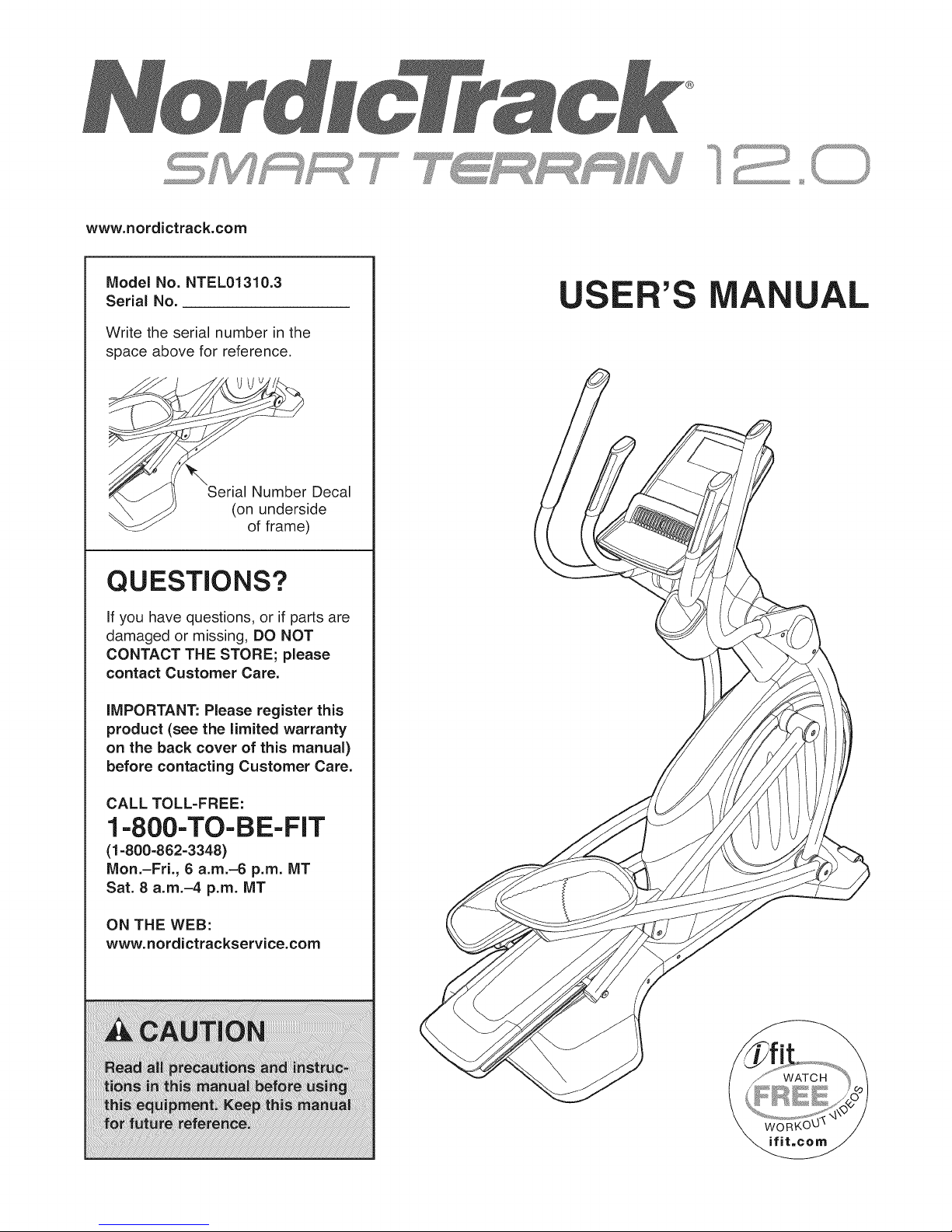
ModelNo.NTEL01310.3
Serial No.
Write the serial number in the
space above for reference.
QUESTIONS?
If you have questions, or if parts are
damaged or missing, DO NOT
CONTACT THE STORE; please
contact Customer Care.
A UAL
Decal
ide
)
IMPORTANT: Please register this
product (see the limited warranty
on the back cover of this manual)
before contacting Customer Care.
CALL TOLL-FREE:
1-800-TO-BE-FIT
(1-800-862-3348)
Mon.-Fri., 6 a.m.-6 p.m. MT
Sat. 8 a.m.-4 p.m. MT
ON THE WEB:
www.nordictrackservice.com
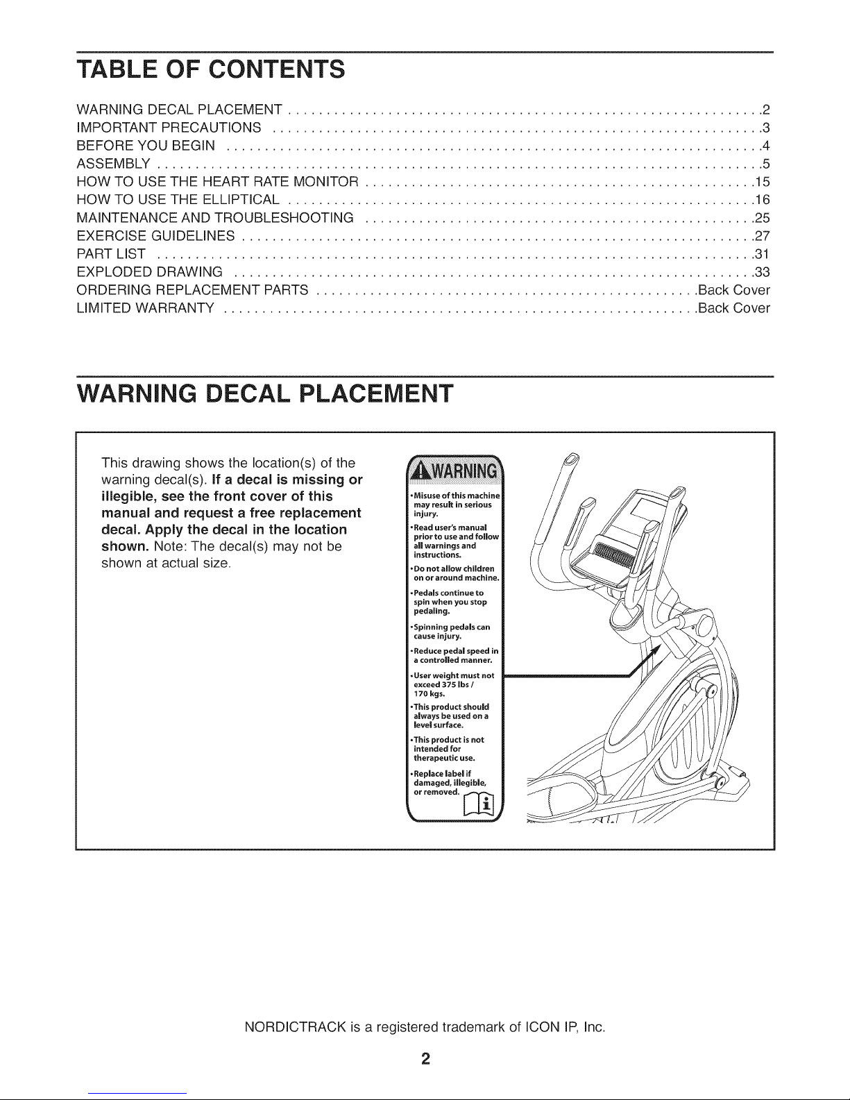
TABLE OF CONTENTS
WARNING DECAL PLACEMENT .............................................................. 2
IMPORTANT PRECAUTIONS ................................................................ 3
BEFORE YOU BEGIN ...................................................................... 4
ASSEMBLY ............................................................................... 5
HOW TO USE THE HEART RATE MONITOR ................................................... 15
HOW TO USE THE ELLIPTICAL ............................................................. 16
MAINTENANCE AND TROUBLESHOOTING ................................................... 25
EXERCISE GUIDELINES ................................................................... 27
PART LIST .............................................................................. 31
EXPLODED DRAWING .................................................................... 33
ORDERING REPLACEMENT PARTS .................................................. Back Cover
LIMITED WARRANTY .............................................................. Back Cover
WARNING DECAL PLACEMENT
This drawing shows the location(s) of the
warning decal(s). If a decal is missing or
illegible, see the front cover of this
manual and request a free replacement
decal. Apply the decal in the location
shown. Note: The decal(s) may not be
shown at actual size.
NORDICTRACK is a registered trademark of ICON IP, Inc.
2
iMPORTANT PRECAUTIONS
WARNING: Toreducethe.s.ofserious njury,reada.importantprecautionsand
instructions in this manual and all warnings on your elliptical before using your elliptical. ICON
assumes no responsibility for personal injury or property damage sustained by or through the use of
this product.
,
Before beginning any exercise program, 9.
consult your physician. This is especially
important for persons over age 35 or
persons with pre-existing health problems. 10.
,
Use the elliptical only as described in this
manual.
The elliptical should not be used by persons
weighing more than 375 Ibs. (170 kg).
Wear appropriate clothes while exercising;
do not wear loose clothes that could become
caught on the elliptical. Always wear athletic
shoes for foot protection while exercising.
3. it is the responsibility of the owner to ensure
that all users of the elliptical are adequately
informed of all precautions.
=
The elliptical is intended for home use only.
Do not use the elliptical in a commercial,
rental, or institutional setting.
.
Keep the elliptical indoors, away from
moisture and dust. Do not put the elliptical in
a garage or covered patio, or near water.
.
Place the elliptical on a level surface, with at
least 3 ft. (0.9 m) of clearance in the front
and rear of the elliptical and 2 ft. (0.6 m) on
each side. To protect the floor or carpet from
damage, place a mat under the elliptical.
.
inspect and properly tighten aH parts
regularly. Replace any worn parts
immediately.
.
Keep children under age 12 and pets away
from the elliptical at all times.
11. Hold the handlebars or the upper body arms
when mounting, dismounting, or using the
elliptical.
12.
The pulse sensor is not a medical device.
Various factors may affect the accuracy of
heart rate readings. The pulse sensor is
intended only as an exercise aid in
determining heart rate trends in general.
13.
The elliptical does not have a freewheel; the
pedals will continue to move until the
flywheel stops. Reduce your pedaling speed
in a controlled way.
14.
Keep your back straight while using the
elliptical; do not arch your back.
15.
Over exercising may result in serious injury
or death, if you feel faint or if you experience
pain while exercising, stop immediately and
cool down.
3
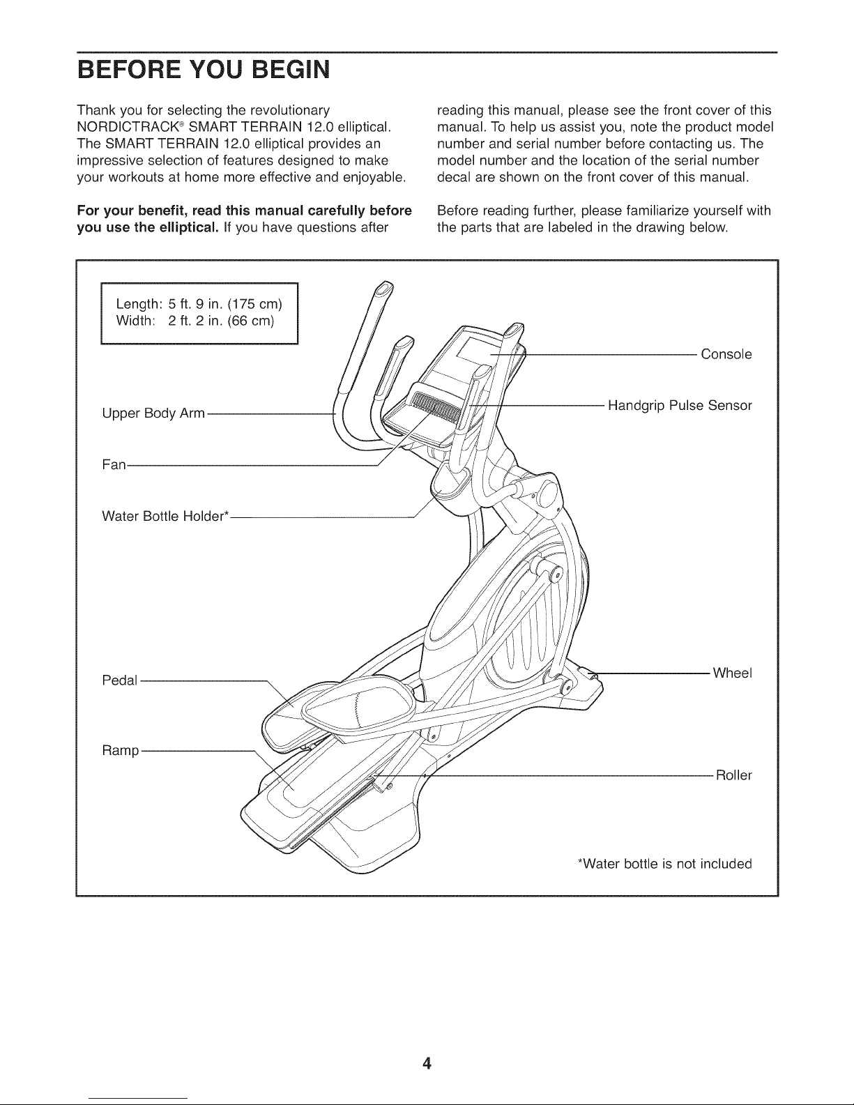
BEFORE YOU BEGIN
Thank you for selecting the revolutionary
NORDICTRACK ®SMART TERRAIN 12.0 elliptical.
The SMART TERRAIN 12.0 elliptical provides an
impressive selection of features designed to make
your workouts at home more effective and enjoyable.
For your benefit, read this manual carefully before
you use the elliptical. Ifyou have questions after
Length: 5 ft. 9 in. (175 cm)
Width: 2 ft. 2 in. (66 cm)
Upper Body Arm
Fan
Water Bottle
reading this manual, please see the front cover of this
manual. To help us assist you, note the product model
number and serial number before contacting us. The
model number and the location of the serial number
decal are shown on the front cover of this manual.
Before reading further, please familiarize yourself with
the parts that are labeled in the drawing below.
Console
Handgrip Pulse Sensor
Pedal
Ramp
Wheel
\
Roller
*Water bottle is not included
4
ASSEMBLY
Assembly requires two persons. Place all parts of the elliptical in a cleared area and remove the packing
materials. Do not dispose of the packing materials until assembly is completed.
in addition to the included tool(s), assembly requires a Phillips screwdriver _L_===_, an adjustable
wrench __, and a rubber mallet _.
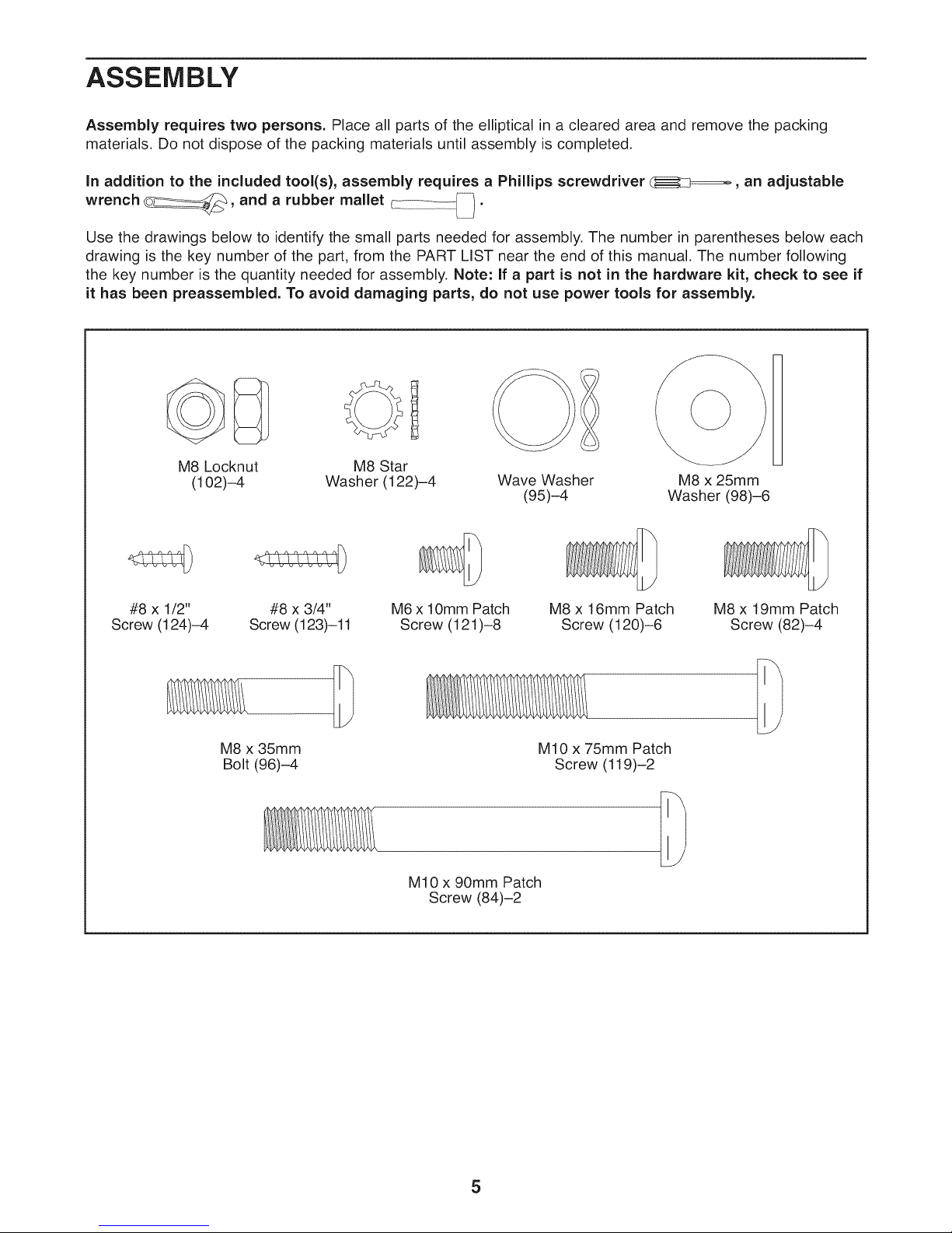
Use the drawings below to identify the small parts needed for assembly. The number in parentheses below each
drawing is the key number of the part, from the PART LIST near the end of this manual. The number following
the key number is the quantity needed for assembly. Note: If a part is not in the hardware kit, check to see if
it has been preassembled. To avoid damaging parts, do not use power tools for assembly.
1
M8 Locknut
#8 x 1/2"
Screw (124)-4
(102)-4
M8 x 35mm
Bolt (96)-4
Washer (122)-4
#8 x 3/4"
Screw (123)-11
M8 Star
M6 x 10mm Patch
Screw (121)-8
M10 x 90mm Patch
Wave Washer
Screw (84)-2
(95)-4
M8 x 16mm Patch
Screw (120)-6
M10 x 75mm Patch
Screw (119)-2
M8 x 25mm
Washer (98)-6
M8 x 19mm Patch
Screw (82)-4
5
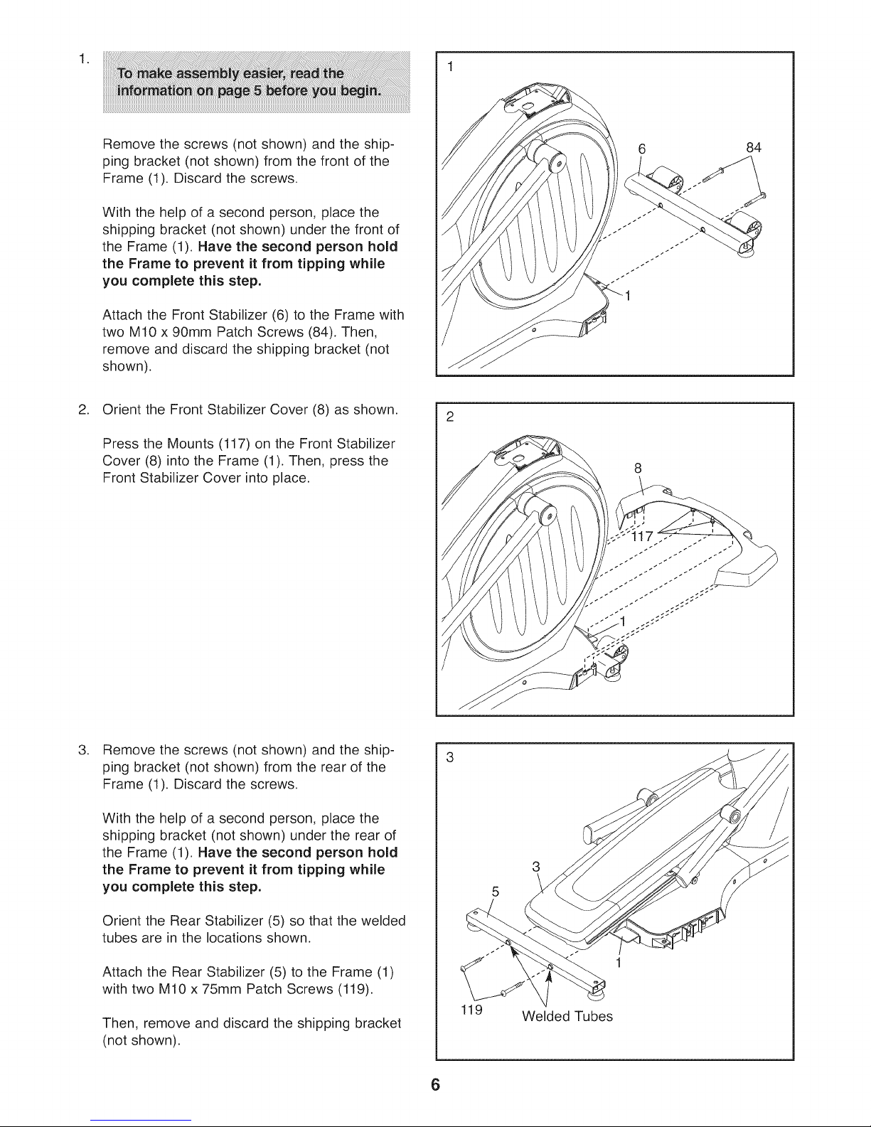
Remove the screws (not shown) and the ship-
ping bracket (not shown) from the front of the
Frame (1). Discard the screws.
With the help of a second person, place the
shipping bracket (not shown) under the front of
the Frame (1). Have the second person hold
the Frame to prevent it from tipping while
you complete this step.
Attach the Front Stabilizer (6) to the Frame with
two M10 x 90mm Patch Screws (84). Then,
remove and discard the shipping bracket (not
shown).
2. Orient the Front Stabilizer Cover (8) as shown.
Press the Mounts (117) on the Front Stabilizer
Cover (8) into the Frame (1). Then, press the
Front Stabilizer Cover into place.
6
84
.
Remove the screws (not shown) and the ship-
ping bracket (not shown) from the rear of the
Frame (1). Discard the screws.
With the help of a second person, place the
shipping bracket (not shown) under the rear of
the Frame (1). Have the second person hold
the Frame to prevent it from tipping while
you complete this step.
Orient the Rear Stabilizer (5) so that the welded
tubes are in the locations shown.
Attach the Rear Stabilizer (5) to the Frame (1)
with two M10 x 75mm Patch Screws (119).
Then, remove and discard the shipping bracket
(not shown).
3
5
1
119 Welded Tubes
6

4. Orient the Rear Stabilizer Cover (2) as shown.
Press the Mounts (117) on the Rear Stabilizer
Cover (2) into the Frame (1). Then, press the
Rear Stabilizer Cover into place.
,
Have a second person hold the Upright (4) near
the Frame (1).
See the inset drawing. Locate the wire tie in
the lower end of the Upright (4). Tie the wire tie
to the Main Wire (110). Then, pull the upper end
of the wire tie until the Main Wire is routed
through the Upright.
4
117
Wire
_Tie
4
110
i
Tip: To prevent the Main Wire (110) from
failing into the Upright (4), secure the Main
Wire with the wire tie.
,
Tip: Avoid pinching the Main Wire (110). Set
the Upright (4) on the Frame (1).
Attach the Upright (4) with four M8 x 19mm
Patch Screws (82) and four M8 Star Washers
(122).
110
9
Tie
82
22
110
Avoid pinching the
Main Wire (110)
7
1\
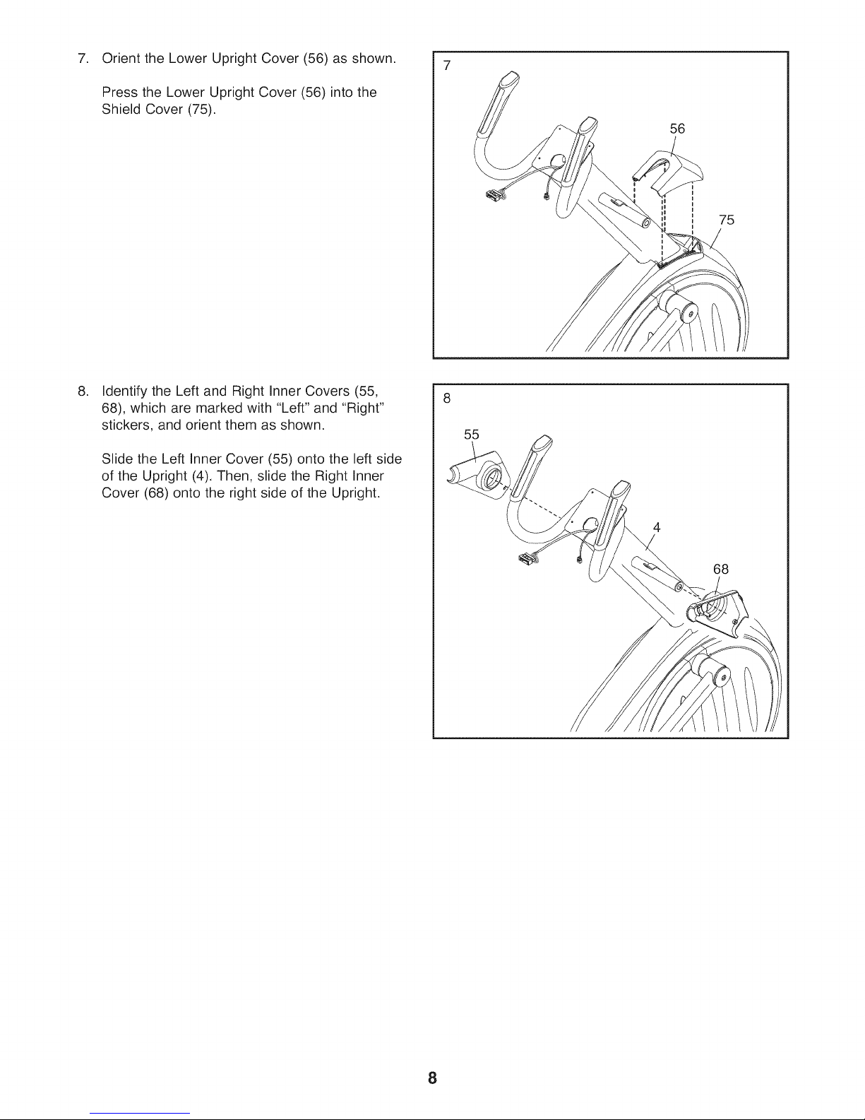
Orient the Lower Upright Cover (56) as shown.
7. 7
Press the Lower Upright Cover (56) into the
Shield Cover (75).
.
Identify the Left and Right Inner Covers (55,
68), which are marked with "Left" and "Right"
stickers, and orient them as shown.
Slide the Left Inner Cover (55) onto the left side
of the Upright (4). Then, slide the Right Inner
Cover (68) onto the right side of the Upright.
56
75
8
55
4
68
8
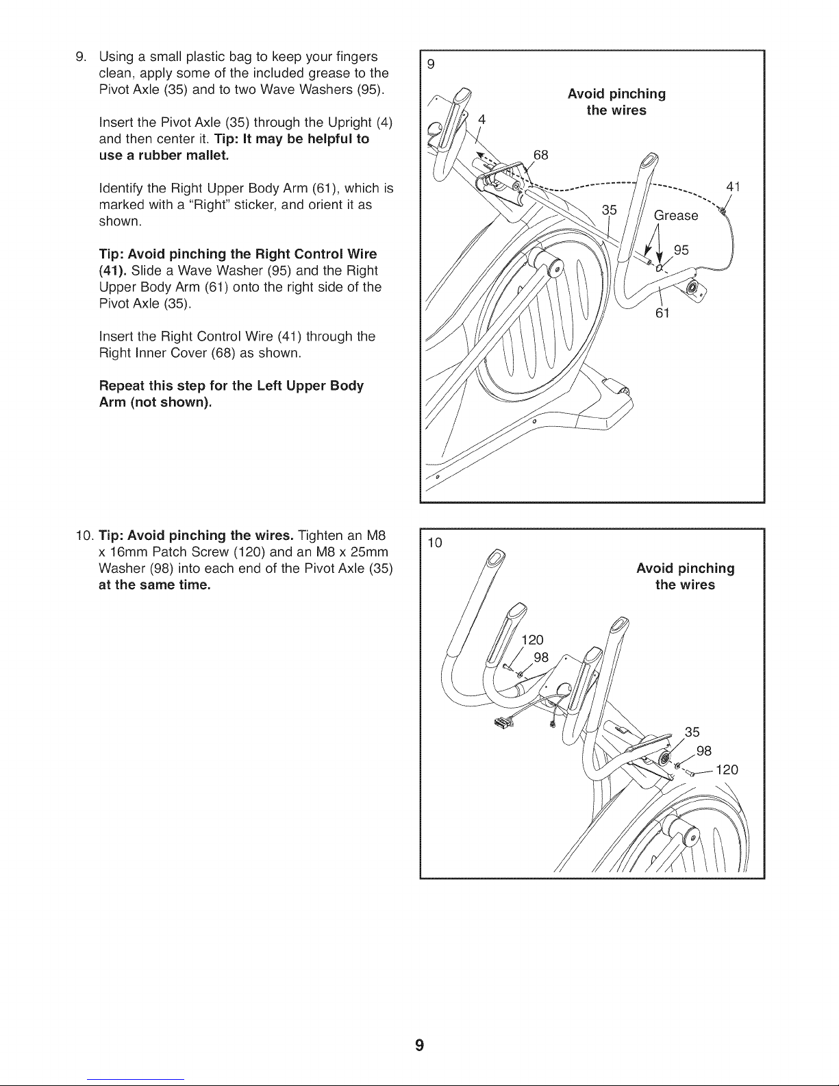
Using a small plastic bag to keep your fingers
9. 9
clean, apply some of the included grease to the
Pivot Axle (35) and to two Wave Washers (95).
Insert the Pivot Axle (35) through the Upright (4)
and then center it. Tip: It may be helpful to
use a rubber mallet.
Avoid pinching
4
68
the wires
Identify the Right Upper Body Arm (61), which is
marked with a "Right" sticker, and orient it as
shown.
Tip: Avoid pinching the Right Control Wire
(41). Slide a Wave Washer (95) and the Right
Upper Body Arm (61) onto the right side of the
Pivot Axle (35).
Insert the Right Control Wire (41) through the
Right Inner Cover (68) as shown.
Repeat this step for the Left Upper Body
Arm (not shown).
10. Tip: Avoid pinching the wires. Tighten an M8
x 16mm Patch Screw (120) and an M8 x 25mm
Washer (98) into each end of the Pivot Axle (35)
at the same time.
41
95
61
10
Avoid pinching
the wires
35
98
120
9
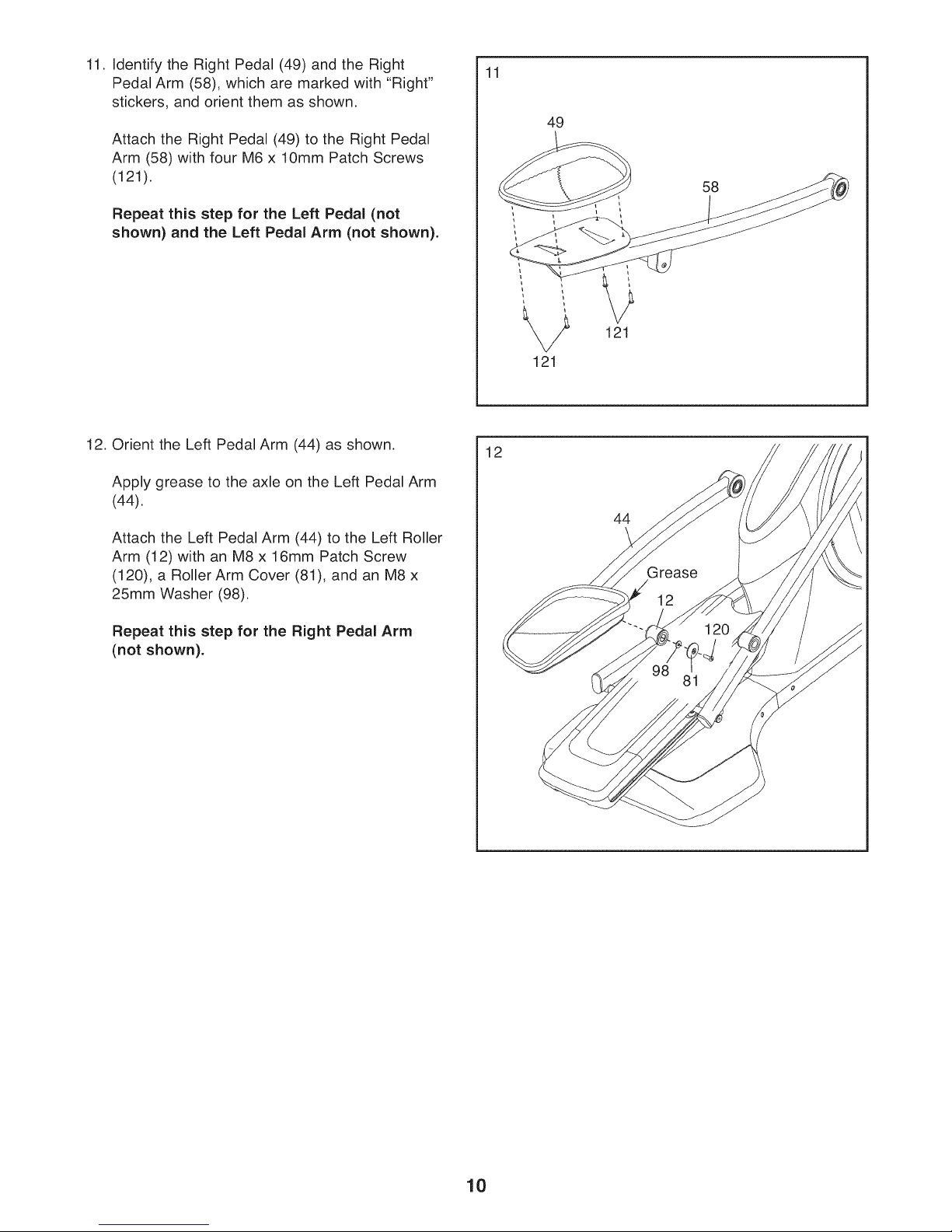
11. Identify the Right Pedal (49) and the Right
Pedal Arm (58), which are marked with "Right"
stickers, and orient them as shown.
Attach the Right Pedal (49) to the Right Pedal
Arm (58) with four M6 x 10mm Patch Screws
(121).
Repeat this step for the Left Pedal (not
shown) and the Left Pedal Arm (not shown).
11
49
58
121
121
12. Orient the Left Pedal Arm (44) as shown.
Apply grease to the axle on the Left Pedal Arm
(44).
Attach the Left Pedal Arm (44) to the Left Roller
Arm (12) with an M8 x 16mm Patch Screw
(120), a Roller Arm Cover (81), and an M8 x
25mm Washer (98).
Repeat this step for the Right Pedal Arm
(not shown).
12
44
10
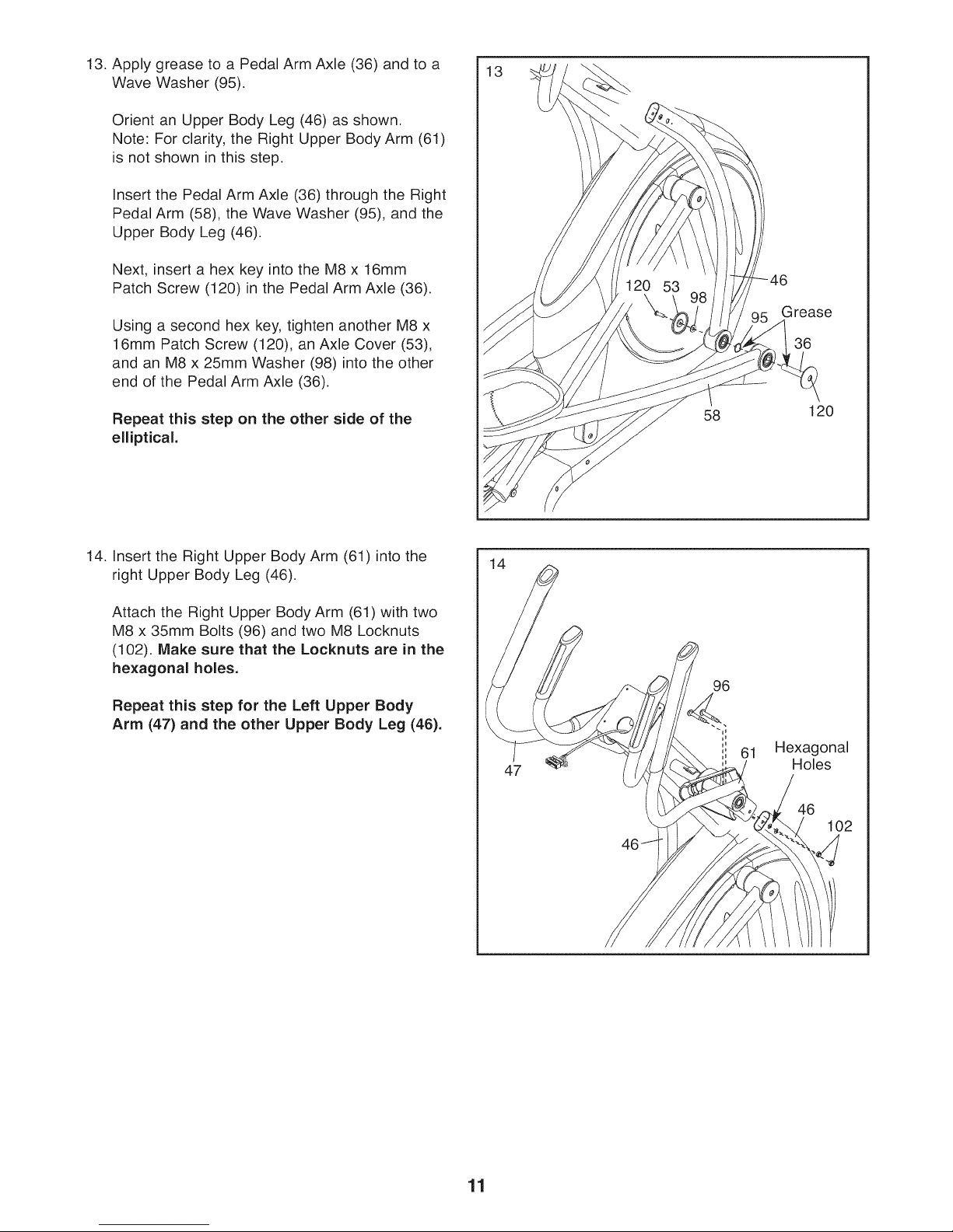
13. Apply grease to a Pedal Arm Axle (36) and to a
Wave Washer (95).
Orient an Upper Body Leg (46) as shown.
Note: For clarity, the Right Upper Body Arm (61)
is not shown in this step.
Insert the Pedal Arm Axle (36) through the Right
Pedal Arm (58), the Wave Washer (95), and the
Upper Body Leg (46).
Next, insert a hex key into the M8 x 16mm
Patch Screw (120) in the Pedal Arm Axle (36).
Using a second hex key, tighten another M8 x
16mm Patch Screw (120), an Axle Cover (53),
and an M8 x 25mm Washer (98) into the other
end of the Pedal Arm Axle (36).
Repeat this step on the other side of the
elliptical.
13
58
Gtease
36
120
14. Insert the Right Upper Body Arm (61)into the
right Upper Body Leg (46).
Attach the Right Upper Body Arm (61) with two
M8 x 35mm Bolts (96) and two M8 Locknuts
(102). Make sure that the Locknuts are in the
hexagonal holes.
Repeat this step for the Left Upper Body
Arm (47) and the other Upper Body Leg (46).
14
47
96
Hexagonal
Holes
46
102
11
 Loading...