

PatentPending
ModelNo.NT007940
Soda1No.
SeriaUNumber
DecaU
QUESTIONS?
As a manufacturer, we are com-
mitted to providing complete
customer satisfaction, if you
have questions, or if there are
missing parts, we wil! guarantee
satisfaction through direct assis-
tance from our factory.
TO AVOID DELAYS, PLEASE
CALL DIRECT TO OUR TOLL-
FREE CUSTOMER NOT LINE.
The trained technicians on our
customer hot line will provide
immediate assistance, free of
charge to you.
CUSTOMER HOT LINE:
1°888°825-2588
Non.=Fd., 6 a.m.=6 p.m. MST
ACAUTION
Read all precautions and instruc-
tions in this manual before using
this equipment. Keep this manual
for future reference.
US
®
:visit ourw÷bsiteat
www.nordictrack.com
new products, prizes,
fitness tips, and much more r.
®
TABLE OF CONTENTS
iMPORTANT PRECAUTIONS ................................................................ 3
BEFORE YOU BEGIN ...................................................................... 4
ASSEMBLY ............................................................................... 5
HOW TO OPERATE THE EXERCISE CYCLE ................................................... 10
MAINTENANCE AND TROUBLESHOOTING ................................................... 22
EXERCHSE GUHDELHNES ................................................................... 23
PART LiST .............................................................................. 25
EXPLODED DRAWHNG .................................................................... 26
HOW TO ORDER REPLACEMENT PARTS ............................................. Back Cover
LiMiTED WARRANTY .............................................................. Back Cover
NordicTrack is a registered trademark of iCON Health & Fitness, inc.
2

iMPORTANT PRECAUTmONS
A WARN ING: Toreducethe.skofseriousinjury, readthefollowing important precau-
tionsbefore using the exercise cycle.
1. Read aH instructions in this manuaJ before 7. Wear euitabJe clothing when using the
using the exercise cyeJe. Use the exercise
cycle onJy as described.
2. It is the responsibility of the owner to
ensure that aH users of the e×ereise cycle
are adequately informed of all precautions.
exercise cycle; do not wear loose clothing
that couJd become caught on the e×ercise
cycle. Always wear atHetic shoes.
8. Always keep your back straight when using
the exercise cycle. Do not arch your back.
3. Use the exercise cycJe indoors on a mevel 9. if you feel pain or dizziness while e×ercia°
surface. Keep the exercise cycJe away from ing, stop immediately and cooJ down.
moisture and dust. Place a mat under the
exercise cycle to protect the floor or carpet. 10. The puJse sensor is not a medicaJ device.
Various factors, including the user's move-
4. inspect and properly tighten alJ parts regu-
larly. FlepJace any worn parts immediately.
5. Keep children under the age of 12 and pets
away from the exercise cycle at aH times.
6. The exercise cycle should not be used by
persons weighing more than 250 pounds.
ment, may affect the accuracy of heart rate
readings. The pulse sensor is intended only
as an exercise aid in determining heart rate
trends in general
11. The exercise cycle is intended for in-home
use onJy. Do not use the exercise cycle in a
commercial, rental, or institutional setting.
"_ WARNING: Beforebeg,nn_ngthisoranyexerciseprogram,eonsultyourphysician.Th,a
is especially important for persons over the age of 35 or persons with pre-existing health problems.
Read aH instructions before using, mCONassumes no responsibility for personal injury or property
damage sustained by or through the use of this product.
3
BEFORE YOU BEGIN
Congratulations for selecting the new NordicTrack _
SL 710 exercise cycle, Cycling is one of the most
effective exercises for increasing cardiovascular fit-
ness, building endurance, and toning the entire body,
The NordicTrack _ SL 710 offers an impressive array
of features designed to let you enjoy this healthful
exercise in the comfort and privacy of your home,
For your benefit, read this manual carefully before
you use the exercise cycle, if you have questions
after reading this manual, call our Customer Service
Department toll-free at 1-888-825-2588, Monday
through Friday, 6 a,m, until 6 p,m, Mountain Time
(excluding holidays), To help us assist you, mention
the product model number and serial number when
calling, The model number is NTC07940, The serial
number can be found on a decal attached to the exer-
cise cycle (see the front cover of this manual for the
location of the decal),
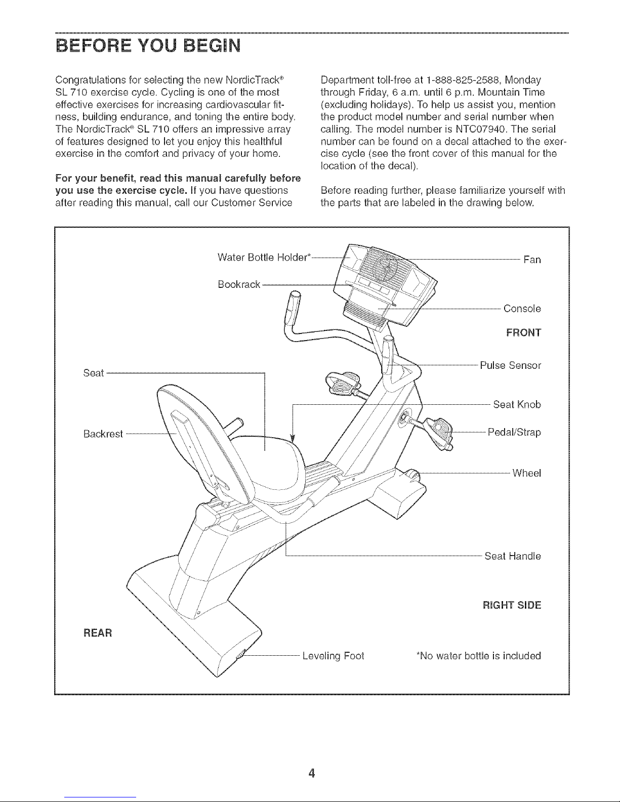
Before reading further, please familiarize yourself with
the parts that are labeled in the drawing below,
Water Bottle
Bookrack
Fan
Console
FRONT
Seat
Pulse Sensor
Seat Knob
Backrest
Wheel
Seat Handle
REAR
Leveling Foot
*No water bottle is included
4
ASSEMBLY
Assembly requires two persons. Hace all parts of the exercise cycle in a cbared area and remove the packing
materiab, Do not dispose of the packing materiab until assembly is compbted,
Assembly requires the included tools and your own adjustable wrench ©___./_.
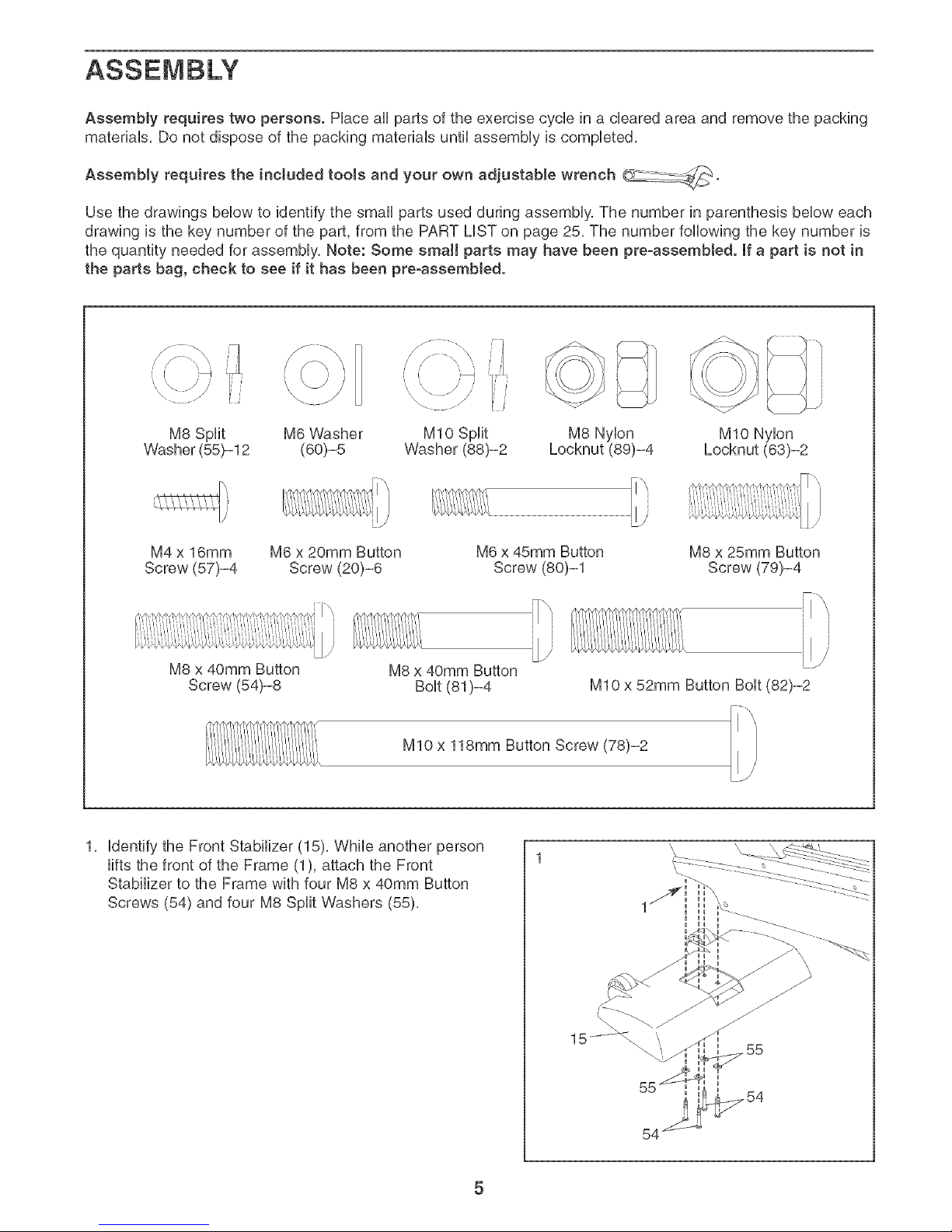
Use the drawings below to identify the small parts used during assembly, The number in parenthesis below each
drawing is the key number of the part, from the PART LiST on page 25, The number following the key number is
the quantity needed for assembly, Note: Some small parts may have been pre-assembJed. [fa part is not in
the parts bag, check to see if it has been pre-assembled.
i' I¸¸ _i
M8 Split M6 Washer M8 Nylon MIO Nylon
Washer (55)-12 (60)-5 Locknut (89)-4
M10 Split
Washer (88)-2
M4 x 16mm
Screw (57)-4
M6 x 20mm Button
Screw (20)-6
M8 x 40mm Button
Screw (54)-8
M6 x 45mm Button
Screw (80)-1
_"\]
ili
M8 x 40mm Button
Bolt (81)-4
M8 x 25mm Button
Screw (79)-4
M10 x 52mm Button Bolt (82)-2
M10 x 118mm Button Screw (78)-2
1, identify the Front Stabilizer (15), While another person
lifts the front of the Frame (1), attach the Front
Stabilizer to the Frame with four M8 x 40mm Button
Screws (54) and four M8 Split Washers (55),
5
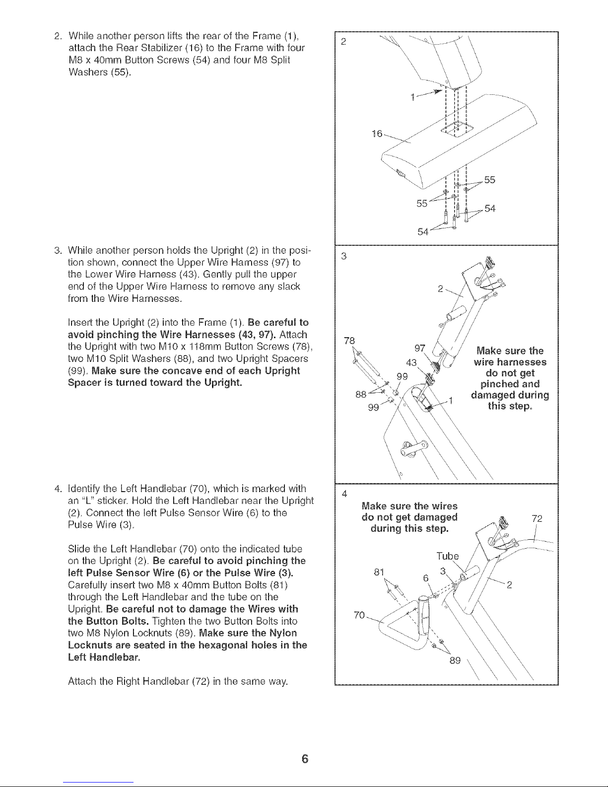
2, While another person Hfts the rear of the Frame (1),
attach the Rear Stabilizer (16) to the Frame with four
M8 x 40mm Button Screws (54) and four M8 Split
Washers (55),
3, While another person hoHdsthe Upright (2) in the posi-
tion shown, connect the Upper Wire Harness (97) to
the Lower Wire Harness (43), Gently puHHthe upper
end of the Upper Wire Harness to remove any shack
from the Wire Harnesses,
Hnsertthe Upright (2) into the Frame (1), Be carefuJ to
avoid pinching the Wire Harnesses (43, 97). Attach
the Upright with two MIO x 118mm Button Screws (78),
two MIO Split Washers (88), and two Upright Spacers
(99), Make sure the concave end of each Upright
Spacer is turned toward the Upright.
4, Hdentifythe Left HandHebar (70), which is marked with
an "U' sticker, HoHdthe Left HandHebar near the Upright
(2), Connect the HeftPuHseSensor Wire (6) to the
PuHseWire (3),
SHde the Left HandHebar (70) onto the indicated tube
on the Upright (2), Be careful to avoid pinching the
teft Pulse Sensor Wire (6} or the Pulse Wire (3}.
CarefuHHyinsert two M8 x 40mm Button BoHts(81)
through the Left HandHebarand the tube on the
Upright, Be careful not to damage the Wires with
the Button BoJts. Tighten the two Button BoHtsinto
two M8 NyHonLocknuts (89), Make sure the NyJon
Locknuts are seated in the he×agonal hotes in the
Left Handlebar.
Attach the Right Handlebar (72) in the same way,
78
\
\
\
54
97
43
99
Make sure the
wire harnesses
do not get
and
damaged during
this step.
Make sure the wires
do not get damaged
during this step.
Tube
81
6
72
89 \
\
\
\
\
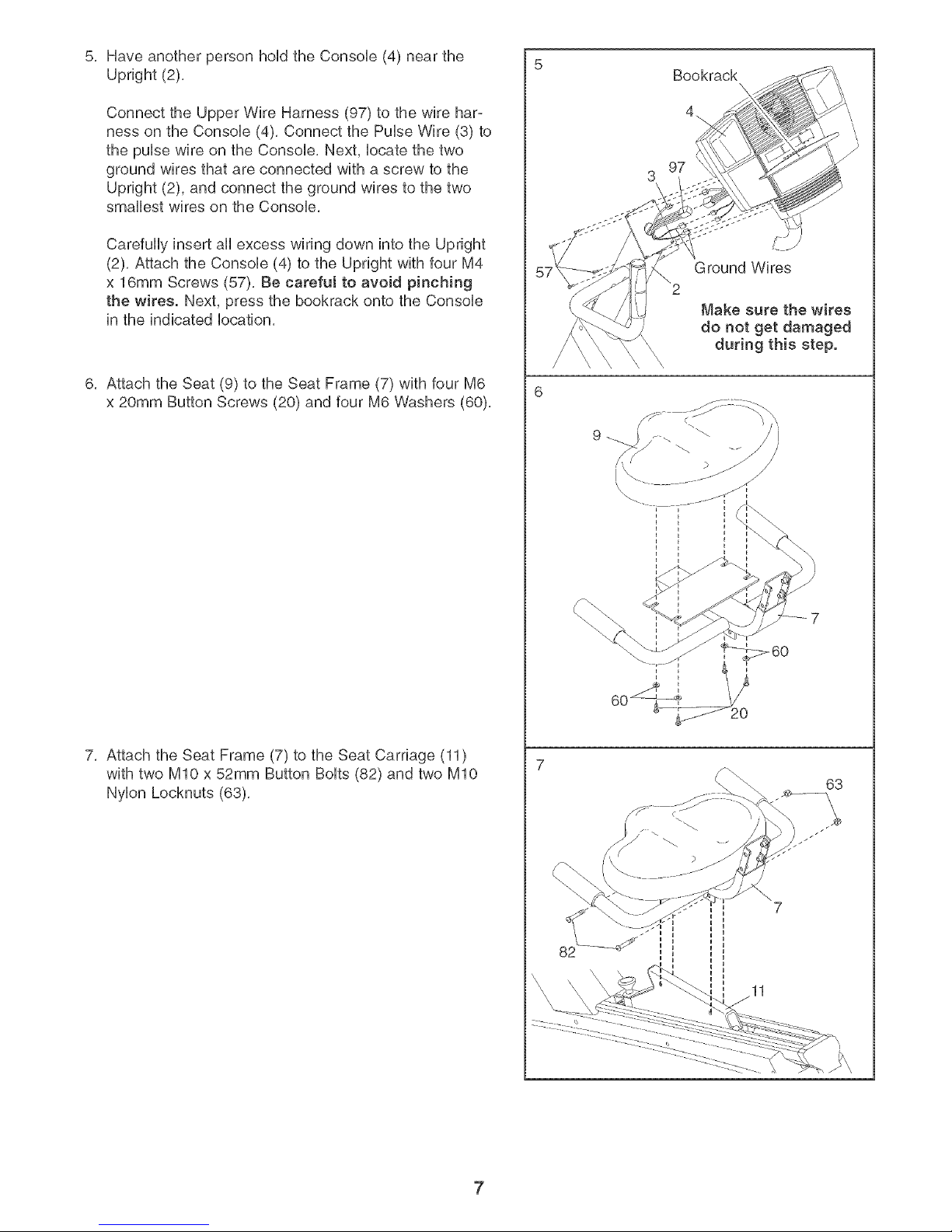
5, Have another person hoUdthe Consob (4) near the
Upright (2),
Connect the Upper Wire Harness (97) to the wire har-
ness on the Consob (4), Connect the Pube Wire (3) to
the puUsewire on the Consob, Next, bcate the two
ground wires that are connected with a screw to the
Upright (2), and connect the ground wires to the two
smallest wires on the Consob,
Carefully insert all excess wiring down into the Upright
(2), Attach the Console (4) to the Upright with four M4
x 16mm Screws (57), Be careful to avoid pinching
the wires. Next, press the bookrack onto the Console
in the indicated location,
6, Attach the Seat (9) to the Seat Frame (7) with four M6
x 20mm Button Screws (20) and four M6 Washers (60),
7, Attach the Seat Frame (7) to the Seat Carriage (11)
with two MIO x 52mm Button Bolts (82) and two MIO
Nylon Locknuts (63),
Bookrack
Ground Wires
Make sure the wires
do not get damaged
during this step.
63
7
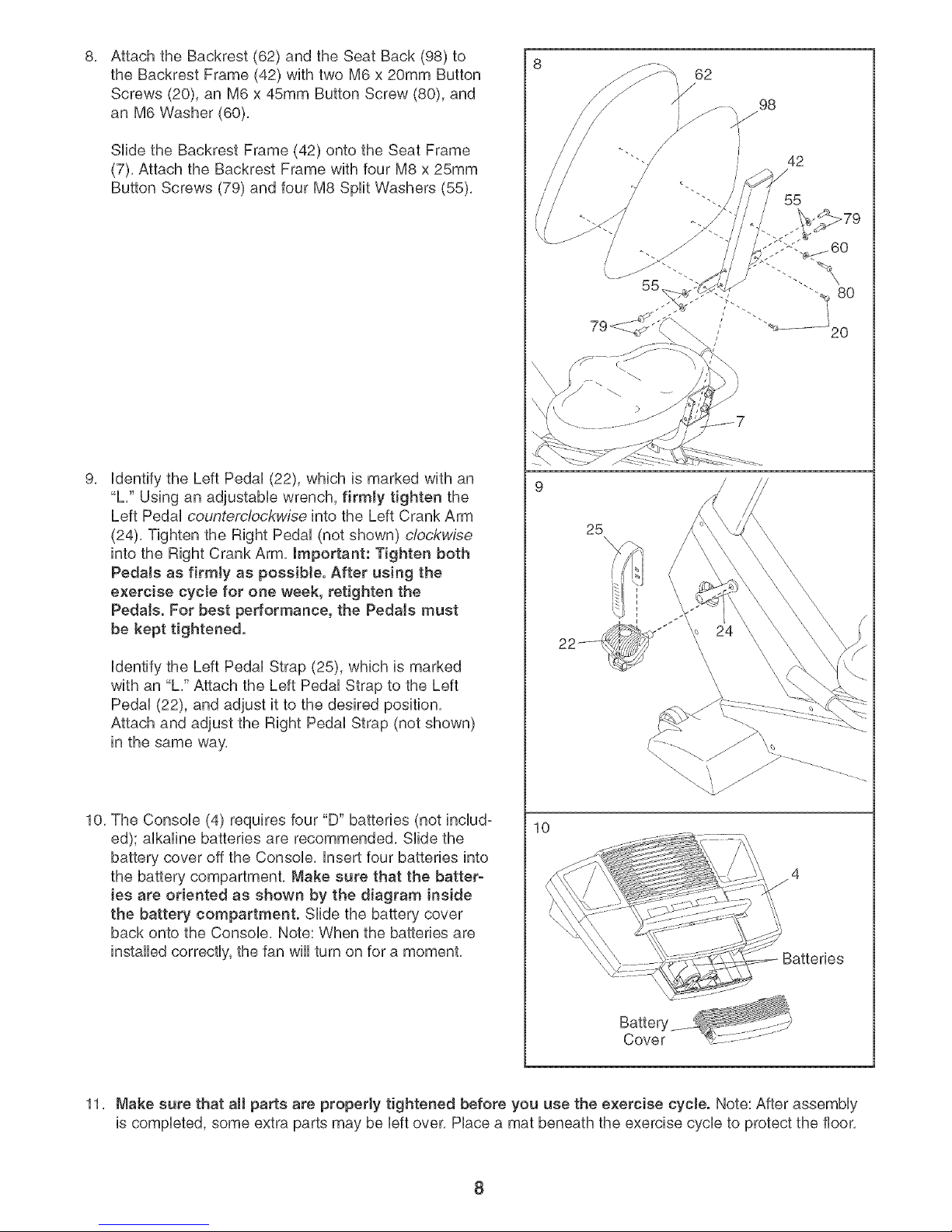
8, 8
Attach the Backrest (62) and the Seat Back (98) to
the Backrest Frame (42) with two M6 x 20mm Button
Screws (20), an M6 x 45mm Button Screw (80), and
an M6 Washer (60),
Slide the Backrest Frame (42) onto the Seat Frame
(7), Attach the Backrest Frame with four M8 x 25mm
Button Screws (79) and four M8 Split Washers (55),
9.
identify the Left Pedal (22), which is marked with an
"L," Using an adjustabb wrench, firmly tighten the
Left Pedal countemlockwise into the Left Crank Arm
(24), Tighten the Right Pedal (not shown) clockwise
into the Right Crank Arm, Important: Tighten both
Pedals as firmly as possible. After using the
exercise cycle for one week, retighten the
Pedals. For best performance, the Pedals must
be kept tightened.
identify the Left Pedal Strap (25), which is marked
with an "L," Attach the Left Pedal Strap to the Left
Pedal (22), and adjust it to the desired position,
Attach and adjust the Right Pedal Strap (not shown)
in the same way,
10, The Console (4) requires four "D" batteries (not includ-
ed); alkaline batteries are recommended, Slide the
battery cover off the Console, insert four batteries into
the battery compartment, Make sure that the batter-
ies are oriented as shown by the diagram inside
the battery compartment. Slide the battery cover
back onto the Console, Note: When the batteries are
installed correctly, the fan will turn on for a moment,
10
/
62
98
/
/
42
/
55
25
Batteries
11, Make sure that aH parts are property tightened before you use the exercise cycle. Note: After assembly
is completed, some extra parts may be left over, Place a mat beneath the exercise cycle to protect the floor,
8
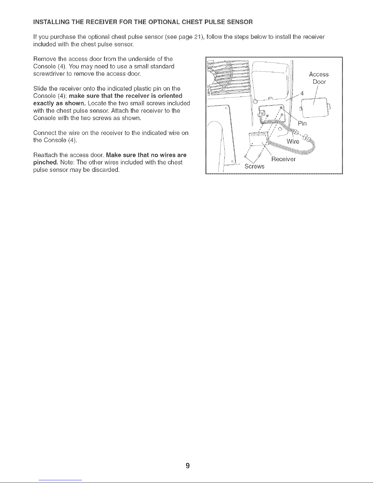
mNSTALUNG THE RECEmVER FOR THE OPTmONAL CHEST PULSE SENSOR
if you purchase the optional chest pulse sensor (see page 21), follow the steps below to install the receiver
included with the chest pulse sensor,
Remove the access door from the underside of the
Console (4). You may need to use a small standard
screwdriver to remove the access door.
Slide the receiver onto the indicated plastic pin on the
Console (4); make sure that the receiver is oriented
e×aetly as shown. Locate the two small screws included
with the chest pulse sensor. Attach the receiver to the
Console with the two screws as shown.
Connect the wire on the receiver to the indicated wire on
the Console (4),
Reattach the access door. Make sure that no wires are
pinched. Note: The other wires included with the chest
pulse sensor may be discarded.
Pin
/ 7 j
Wire
Receiver
9
 Loading...