


www.nordictrack.com
Model No. NTSY14016.0
Serial No.
Write the serial number in the space
above for reference.
Serial Number
Decal
ACTIVATE YOUR
WARRANTY
To register your product and
activate your warranty today, go
to www.nordictrackservice.com/
registration.
USER’S MANUAL
CUSTOMER CARE
For service at any time, go to
www.nordictrackservice.com.
Or call 1-866-608-1798
Mon.–Fri. 6 a.m.–6 p.m. MT
Sat. 8 a.m.–12 p.m. MT
Please do not contact the store.
CAUTION
Read all precautions and
instructions in this manual before
using this equipment. Keep this
manual for future reference.

TABLE OF CONTENTS
WARNING DECAL PLACEMENT . . . . . . . . . . . . . . . . . . . . . . . . . . . . . . . . . . . . . . . . . . . . . . . . . . . . . . . . . . . . . . .2
IMPORTANT PRECAUTIONS ..................................................................3
BEFORE YOU BEGIN. . . . . . . . . . . . . . . . . . . . . . . . . . . . . . . . . . . . . . . . . . . . . . . . . . . . . . . . . . . . . . . . . . . . . . . .5
ASSEMBLY . . . . . . . . . . . . . . . . . . . . . . . . . . . . . . . . . . . . . . . . . . . . . . . . . . . . . . . . . . . . . . . . . . . . . . . . . . . . . . . .6
THE CHEST HEART RATE MONITOR. . . . . . . . . . . . . . . . . . . . . . . . . . . . . . . . . . . . . . . . . . . . . . . . . . . . . . . . . .17
HOW TO USE THE STRENGTH SYSTEM. . . . . . . . . . . . . . . . . . . . . . . . . . . . . . . . . . . . . . . . . . . . . . . . . . . . . . .18
FCC INFORMATION . . . . . . . . . . . . . . . . . . . . . . . . . . . . . . . . . . . . . . . . . . . . . . . . . . . . . . . . . . . . . . . . . . . . . . . .22
MAINTENANCE AND TROUBLESHOOTING .....................................................23
CARDIO EXERCISE GUIDELINES. . . . . . . . . . . . . . . . . . . . . . . . . . . . . . . . . . . . . . . . . . . . . . . . . . . . . . . . . . . . .25
STRENGTH EXERCISE GUIDELINES. . . . . . . . . . . . . . . . . . . . . . . . . . . . . . . . . . . . . . . . . . . . . . . . . . . . . . . . . . 26
PART LIST. . . . . . . . . . . . . . . . . . . . . . . . . . . . . . . . . . . . . . . . . . . . . . . . . . . . . . . . . . . . . . . . . . . . . . . . . . . . . . . .28
EXPLODED DRAWING. . . . . . . . . . . . . . . . . . . . . . . . . . . . . . . . . . . . . . . . . . . . . . . . . . . . . . . . . . . . . . . . . . . . . .30
ORDERING REPLACEMENT PARTS. . . . . . . . . . . . . . . . . . . . . . . . . . . . . . . . . . . . . . . . . . . . . . . . . . . Back Cover
LIMITED WARRANTY. . . . . . . . . . . . . . . . . . . . . . . . . . . . . . . . . . . . . . . . . . . . . . . . . . . . . . . . . . . . . . . Back Cover
WARNING DECAL PLACEMENT
This drawing shows the location(s) of the warning decal(s).
If a decal is missing or illegible, see the front cover of
this manual and request a free replacement decal. Apply
the decal in the location shown. Note: The decal(s) may
not be shown at actual size.
NORDICTRACK is a registered trademark of ICON Health & Fitness, Inc. The BLUETOOTH® word mark and
logos are registered trademarks of Bluetooth SIG, Inc. and are used under license.
2

IMPORTANT PRECAUTIONS
WARNING: To reduce the risk of serious injury, read all important precautions and
instructions in this manual and all warnings on your strength system before using your strength
system. ICON assumes no responsibility for personal injury or property damage sustained by or
through the use of this product.
1. It is the responsibility of the owner to ensure
that all users of the strength system are
adequately informed of all precautions.
2. Before beginning any exercise program,
consult your physician. This is especially
important for persons over age 35 or persons with pre-existing health problems.
3. The strength system is not intended for use
by persons with reduced physical, sensory,
or mental capabilities or lack of experience and knowledge, unless they are given
supervision or instruction about use of the
strength system by someone responsible for
their safety.
4. Use the strength system only as described in
this manual.
5. The strength system is intended for home
use only. Do not use the strength system in a
commercial, rental, or institutional setting.
6. Keep the strength system indoors, away
from moisture and dust. Do not put the
strength system in a garage or covered
patio, or near water.
7. Place the strength system on a level surface
with at least 6 ft. (1.8 m) of clearance around
the strength system. To protect the floor or
carpet from damage, place a mat under the
strength system.
8. Obtain professional advice and have a
qualified person install the brackets to
ensure adequate support. Serious injury
could result if the brackets are improperly
installed.
9. The location on the wall to which the
brackets are fastened must be capable
of supporting a working load of 600 lbs.
(272 kg). Do not fasten the brackets to a drywall surface or to a cinder block surface.
10. Inspect and properly tighten all parts each
time the strength system is used. Replace
any worn parts immediately.
11. Keep children under age 13 and pets away
from the strength system at all times.
12. Users weighing more than 300 lbs. (136 kg)
should not use the strength system.
13. Wear appropriate clothes while exercising;
do not wear loose clothes that could become
caught on the strength system. Always wear
athletic shoes for foot protection.
14. Keep hands and feet away from moving
parts.
15. Pull and release the handles and ankle straps
in a controlled manner.
16. Make sure that the ropes remain on the pulleys at all times. If the ropes bind while you
are exercising, stop immediately and make
sure that the ropes are on the pulleys.
17. Over exercising may result in serious injury
or death. If you feel faint, if you become short
of breath, or if you experience pain while
exercising, stop immediately and cool down.
3
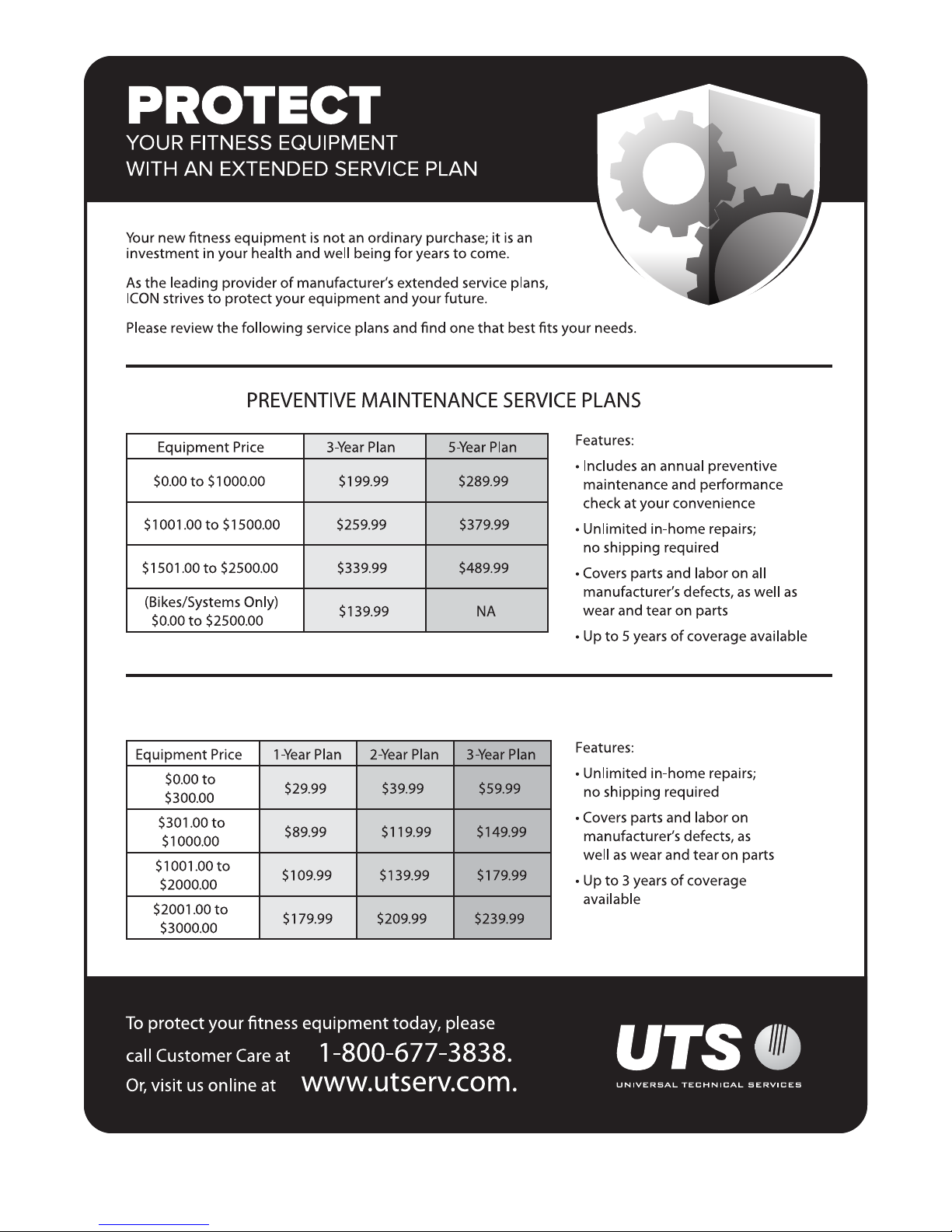
STANDARD SERVICE PLANS
all
4

BEFORE YOU BEGIN
Congratulations for selecting the revolutionary
NORDICTRACK® FUSION CST strength system. The
FUSION CST strength system is unlike any ordinary
strength system. Whether your goal is to tone your
body, build dramatic muscle size and strength, or
improve your cardiovascular system, the strength
system has an array of innovative features that will
help you to achieve the specic results you want.
For your benefit, read this manual carefully before
you use the strength system. If you have questions
Resistance Disc
after reading this manual, please see the front cover
of this manual. To help us assist you, note the product
model number and serial number before contacting us.
The model number and the location of the serial number decal are shown on the front cover of this manual.
Before reading further, please familiarize yourself with
the parts that are labeled in the drawing below.
Length: 1 ft. 1 in. (33 cm)
Width: 5 ft. 1 in. (155 cm)
Height: 6 ft. 2 in. (188 cm)
Tablet Holder
Console
Tablet Stand
Squat Pulley
Squat Leg
Ankle Strap
Clip
Handle
Power Receptacle
Squat Pulley
Squat Leg
5

ASSEMBLY
• Due to the size and weight of the strength system,
assembly requires two or three persons.
• Place all parts in a cleared area and remove the
packing materials. Do not dispose of the packing
materials until you nish all assembly steps.
• Left parts are marked “L” or “Left” and right parts
are marked “R” or “Right.”
• Assembly may be easier if you have your own set
of wrenches. To avoid damaging parts, do not use
power tools for assembly steps 4 to 14.
The Two Stages of the Assembly Process
Wall Bracket Assembly—You will first fasten the
brackets to wood or metal studs in your wall.
• In addition to the included tool(s), assembly
requires the following tools:
Drill with a 1/4" bit or a 7/8" bit
Pencil
Ratchet
Stud nder
Adjustable wrench
Strength System Assembly—You will then attach
the strength system to your wall and assemble
the strength system covers, tower arms, and
accessories.
6

Wall Bracket Assembly
• IMPORTANT: Obtain professional advice
and have a qualied person install the
brackets to ensure adequate support.
• IMPORTANT: Do not fasten the brackets
to a drywall surface or to a cinder block
surface.
• The location on the wall to which the
brackets are fastened must be capable
of supporting a working load of 600 lbs.
(272 kg). IMPORTANT: The brackets and
the strength system should not be used
by persons weighing more than 300 lbs.
(136 kg).
• The brackets must be securely fastened to
the centers of wood or metal wall studs in a
wall that is at least 7 ft. (213 cm) high, above
a at surface that is at least 6 ft. (183 cm)
long and 6 ft. (183 cm) wide. This placement
provides sufcient space to use the strength
system effectively.
• Taking your height into consideration, make
sure that there will be adequate clearance
between the strength system and the ceiling
to perform the exercises that you wish to
perform with the strength system.
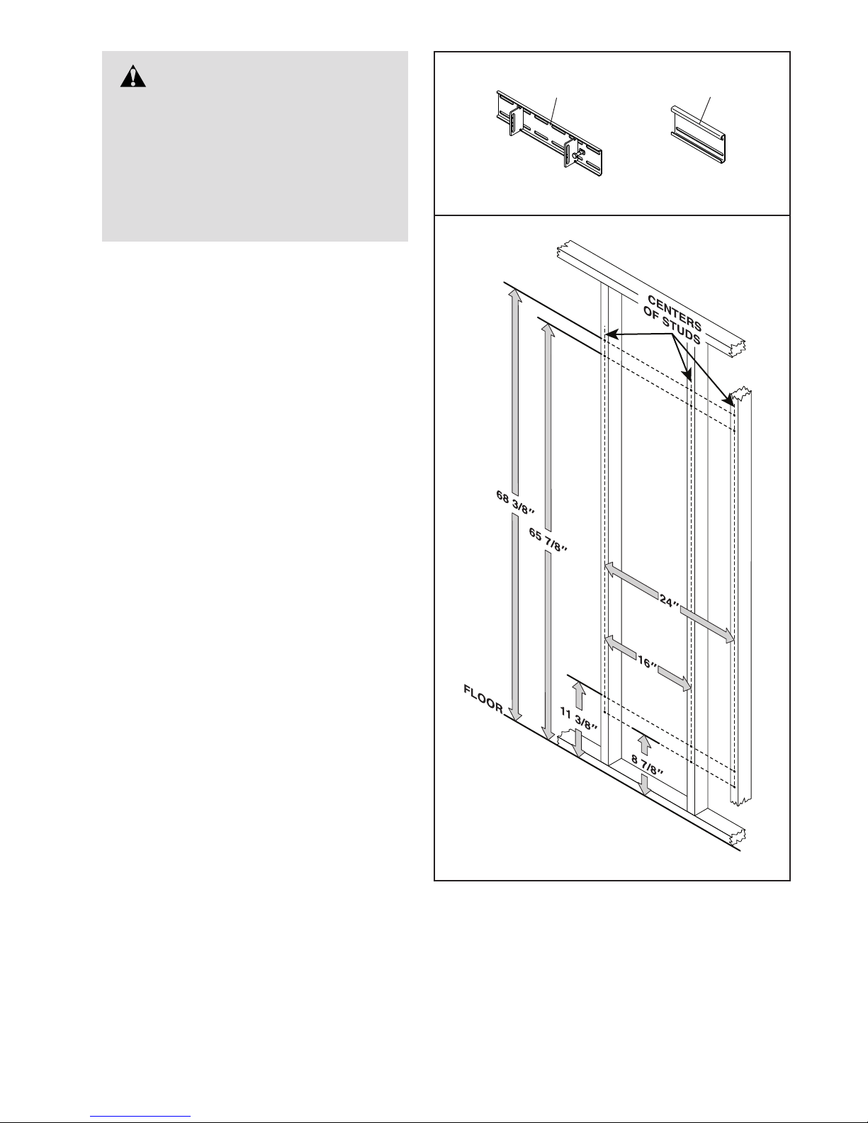
• The upper brackets. The upper hole in
each bracket must be positioned 68 3/8 in.
(174 cm) above the oor. Measuring from
upper hole to upper hole, the brackets must
be positioned 16–24 in. (41–61 cm) apart.
• The lower brackets. The lower hole in
each bracket must be positioned 8 7/8 in.
(22.5 cm) above the oor. Measuring from
lower hole to lower hole, the brackets must
be positioned 16–24 in. (41–61 cm) apart.
• If you are fastening the brackets to a
concrete surface, you will also need eight
3/8" lag screws (not included) designed
for use with eight concrete lag anchors
(not included). Follow the manufacturer’s
instructions to install the 3/8" lag screws and
the concrete lag anchors.
7
1.
WARNING: Serious injury
could result if the Slide Brackets (60)
or Wall Brackets (61) are improperly
installed. Obtain professional advice
and have a qualied person install the
Slide Brackets or Wall Brackets. Do
not fasten the Slide Brackets or Wall
Brackets to a drywall surface or to a
cinder block surface.
Identify the Slide Brackets (60) and the Wall
Brackets (61).
Using your stud finder, locate the centers of two
wood or metal wall studs. IMPORTANT: Each
Bracket (60, 61) must be fastened to the
center of a wood or metal wall stud. The wall
studs can be no more than 24 in. (61 cm) and
no less than 16 in. (41 cm) apart.
If your wall studs are 16 in. (41 cm) apart,
go to step 2. You will use only the Slide
Brackets (60) to assemble the strength system.
Note: Save the unused Wall Brackets (61) in
case you need to mount the strength system
differently in the future.
1
60
61
If your wall studs are 24 in. (61 cm) apart, go
to step 3. You will use the Slide Brackets (60)
and the Wall Brackets (61).
8

2. Align a Slide Bracket (60) along the centers
of the wall studs. Using your pencil, mark the
locations of the slots on the wall studs. Then,
remove the Slide Bracket.
Repeat these actions for the other Slide
Bracket (60).
Using your drill, drill pilot holes in the marked
locations on the wall. Drill 1/4" pilot holes in
wood wall studs. Drill 7/8" pilot holes in metal
wall studs. IMPORTANT: The pilot holes must
be drilled straight and perpendicular to the
center of the wall stud.
2
Wood Studs
60
103
104
103
Metal Studs
104
Wood Wall Studs. If you are installing the
Slide Bracket (60) in wood wall studs, see
the upper drawing. Locate the 3/8" x 3" Screws
(103) and the 3/8" x 1 1/4" Washers (104). Align
a Slide Bracket with two sets of pilot holes.
Using your ratchet or drill, tighten four Screws
with four Washers into the Slide Bracket and the
pilot holes. Start all the Screws, and then fully
tighten them.
Metal Wall Studs. If you are installing the
Slide Bracket (60) in metal wall studs, see
the center drawing. Locate the M10 x 100mm
Toggle Bolts (105). Align a Slide Bracket with
two sets of pilot holes. Using your ratchet or drill,
tighten four Toggle Bolts into the Slide Bracket
and the pilot holes; make sure to orient the
Toggle Bolts so that the wings (A) will open
vertically. Start all the Toggle Bolts, and then
fully tighten them.
Repeat these actions for the other Slide
Bracket (60).
Make sure that each Slide Bracket (60) is
flush with the wall and that the 3/8" x 3"
Screws (103) or the M10 x 100mm Toggle
Bolts (105) are firmly tightened. Pull firmly on
each Slide Bracket. There must not be any
movement or play in the Slide Brackets.
105
A
60
A
105
Then, go to step 4.
9
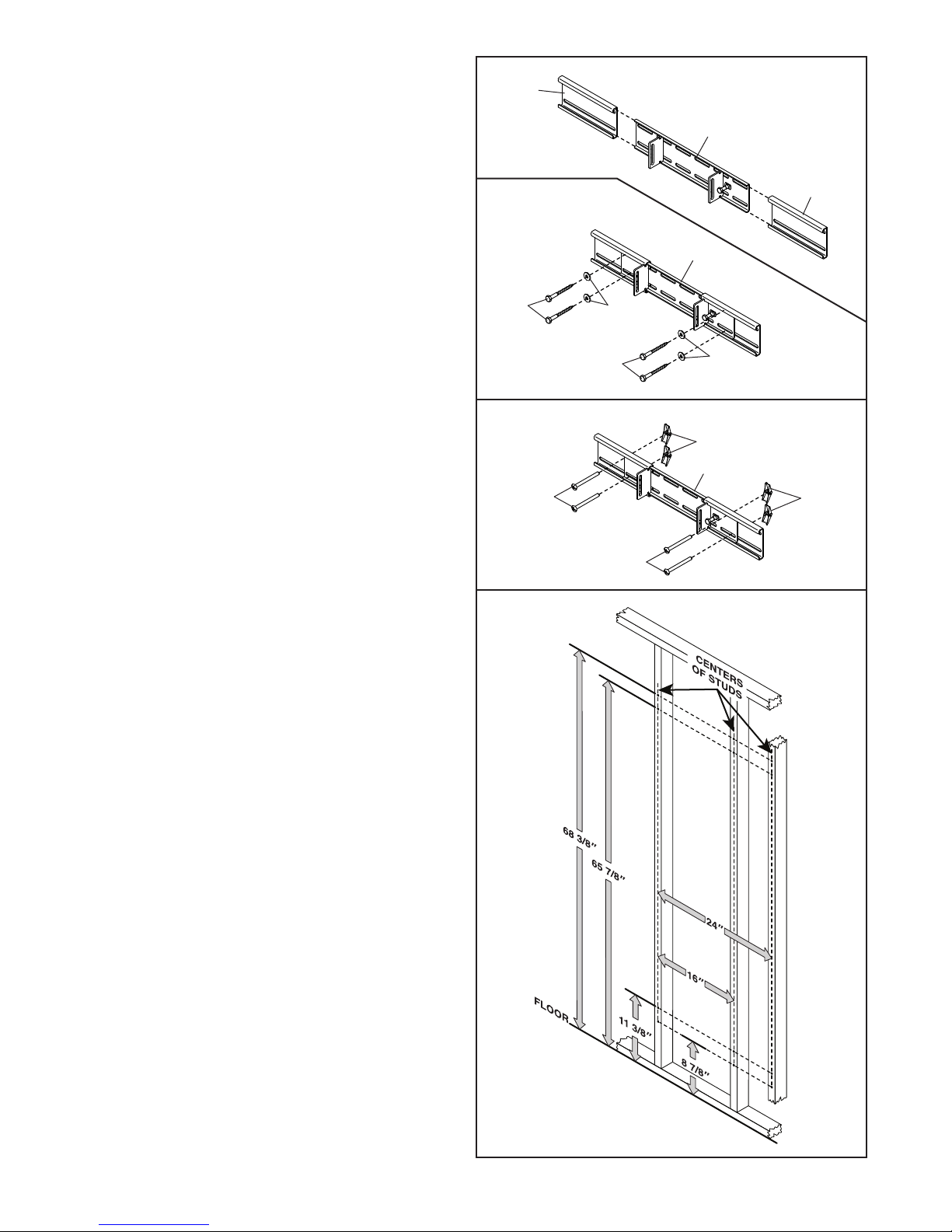
3. See the upper drawing. Slide a Wall Bracket
(61) onto each side of a Slide Bracket (60).
3
61
Align the Slide Bracket (60) assembly along
the centers of the wall studs. Adjust the Wall
Brackets (61) as needed. Using your pencil,
mark the locations of the slots on the wall studs.
Then, remove the Slide Bracket assembly.
Repeat these actions for the other Slide
Bracket (60) assembly.
Using your drill, drill pilot holes in the marked
locations on the wall. Drill 1/4" pilot holes in
wood wall studs. Drill 7/8" pilot holes in metal
wall studs. IMPORTANT: The pilot holes must
be drilled straight and perpendicular to the
center of the wall stud.
Wood Wall Studs. If you are installing the
Slide Bracket (60) assembly in wood wall
studs, see the second drawing. Locate the
3/8" x 3" Screws (103) and the 3/8" x 1 1/4"
Washers (104). Align a Slide Bracket assembly
with two sets of pilot holes. Using your ratchet or
drill, tighten four Screws with four Washers into
the Slide Bracket assembly and the pilot holes.
Start all the Screws, and then fully tighten
them.
Wood
Studs
103
Metal
Studs
105
104
103
60
61
60
104
A
60
A
105
Metal Wall Studs. If you are installing the
Slide Bracket (60) assembly in metal wall
studs, see the third drawing. Locate the
M10 x 100mm Toggle Bolts (105). Align a Slide
Bracket assembly with two sets of pilot holes.
Using your ratchet or drill, tighten four Toggle
Bolts into the Slide Bracket assembly and the
pilot holes; make sure to orient the Toggle
Bolts so that the wings (A) will open vertically. Start all the Toggle Bolts, and then fully
tighten them.
Repeat these actions for the other Slide
Bracket (60) assembly.
Make sure that each Slide Bracket (60) is
flush with the wall and that the 3/8" x 3"
Screws (103) or the M10 x 100mm Toggle
Bolts (105) are firmly tightened. Pull firmly on
each Slide Bracket. There must not be any
movement or play in the Slide Brackets.
Then, go to step 4.
10
 Loading...