

CAUTION
Read all precautions and instructions in this manual before using
this equipment. Save this manual
for future reference.
¨
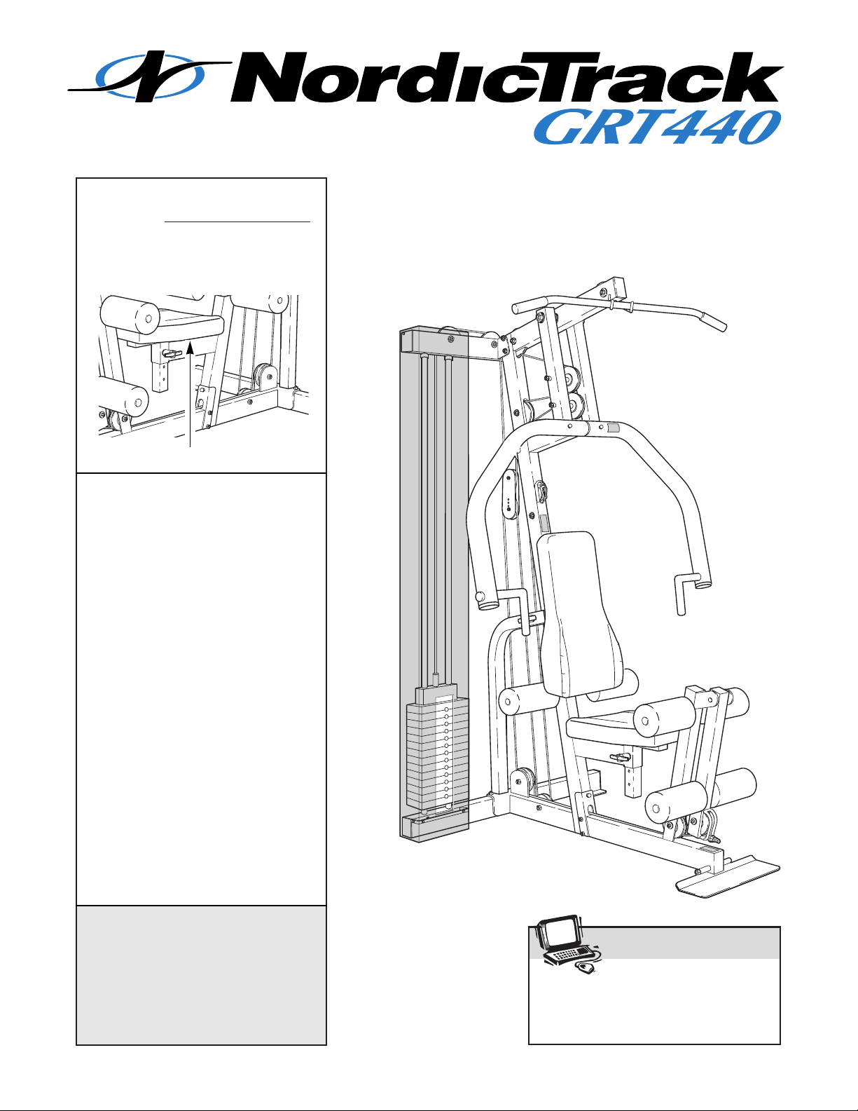
Model No. NTSY06990
Serial No.
The serial number is found in the
location shown below. Write the
serial number in the space above.
QUESTIONS?
As a manufacturer, we are
committed to providing complete
customer satisfaction. If you
have questions, or if there are
missing or damaged parts, we
will guarantee complete satisfaction through direct assistance
from our factory.
TO AVOID UNNECESSARY
DELAYS, PLEASE CALL DIRECT
TO OUR TOLL-FREE CUSTOMER
HOT LINE. The trained technicians on our customer hot line
will provide immediate assistance, free of charge to you.
CUSTOMER HOT LINE:
1-888-825-2588
Mon.ÐFri., 6 a.m.Ð6 p.m. MST
Patent Pending
Serial Number Decal
Visit our website at
www.nordictrack.com
new products, prizes,
fitness tips, and much more!
USERÕS MANUAL

2
Limited Warranty . . . . . . . . . . . . . . . . . . . . . . . . . . . . . . . . . . . . . . . . . . . . . . . . . . . . . . . . . . . . . . . . . . . . . . . 2
Important Precautions . . . . . . . . . . . . . . . . . . . . . . . . . . . . . . . . . . . . . . . . . . . . . . . . . . . . . . . . . . . . . . . . . . . 3
Before You Begin . . . . . . . . . . . . . . . . . . . . . . . . . . . . . . . . . . . . . . . . . . . . . . . . . . . . . . . . . . . . . . . . . . . . . . 4
Assembly . . . . . . . . . . . . . . . . . . . . . . . . . . . . . . . . . . . . . . . . . . . . . . . . . . . . . . . . . . . . . . . . . . . . . . . . . . . . 5
Cable Diagram . . . . . . . . . . . . . . . . . . . . . . . . . . . . . . . . . . . . . . . . . . . . . . . . . . . . . . . . . . . . . . . . . . . . . . . 16
Adjustment . . . . . . . . . . . . . . . . . . . . . . . . . . . . . . . . . . . . . . . . . . . . . . . . . . . . . . . . . . . . . . . . . . . . . . . . . . 17
Trouble-shooting and Maintenance . . . . . . . . . . . . . . . . . . . . . . . . . . . . . . . . . . . . . . . . . . . . . . . . . . . . . . . . 19
Ordering Replacement Parts . . . . . . . . . . . . . . . . . . . . . . . . . . . . . . . . . . . . . . . . . . . . . . . . . . . . . . Back Cover
Weight Resistance Chart . . . . . . . . . . . . . . . . . . . . . . . . . . . . . . . . . . . . . . . . . . . . . . . . . . . . . . . . . Back Cover
Note: A PART LIST/EXPLODED DRAWING and a PART IDENTIFICATION CHART are attached in the center of
this manual.
Table of Contents
WHAT IS COVEREDÑThe entire NordicTrack¨GRT440 Training System (ÒProductÓ) is warranted to be free of all defects in
material and workmanship.
WHO IS COVEREDÑThe original purchaser or any person receiving the Product as a gift from the original purchaser.
HOW LONG IS IT COVEREDÑICON Health & Fitness, Inc. (ÒICONÓ), warrants the product for one year after the date of purchase. Labor is covered for one year.
WHAT WE DO TO CORRECT COVERED DEFECTSÑWe will ship to you, without charge, any replacement part or component,
providing the repairs are authorized by ICON first and are performed by an ICON trained and authorized service provider, or, at
our option, we will replace the Product.
WHAT IS NOT COVEREDÑAny failures or damage caused by unauthorized service, misuse, accident, negligence, improper
assembly or installation, alterations, modifications without our written authorization or by failure on your part to use, operate,
and maintain as set out in your UserÕs Manual (ÒManualÓ).
WHAT YOU MUST DOÑAlways retain proof of purchase, such as your bill of sale; store, operate, and maintain the Product as
specified in the Manual; notify our Customer Service Department of any defect within 10 days after discovery of the defect; as
instructed, return any defected part for replacement or, if necessary, the entire product, for repair.
USERÕS MANUALÑIt is VERY IMPORTANT THAT YOU READ THE MANUAL before operating the Product. Remember to do
the periodic maintenance requirements specified in the Manual to assure proper operation and your continued satisfaction.
HOW TO GET PARTS AND SERVICEÑSimply call our Customer Service Department at 1-888-825-2588 and tell them your
name and address and the serial number of your Product. They will tell you how to get a part replaced, or if necessary, arrange
for service where your Product is located or advise you how to ship the Product for service. Before shipping, always obtain a
Return Authorization Number (RA No.) from our Customer Service Department; securely pack your Product (save the original
shipping carton if possible); put the RA No. on the outside of the carton and insure the product. Include a letter explaining the
product or problem and a copy of your proof of purchase if you believe the service is covered by warranty.
ICON is not responsible or liable for indirect, special or consequential damages arising out of or in connection with the use or
performance of the product or damages with respect to any economic loss, loss of property, loss of revenues or profits, loss of
enjoyment or use, costs of removal, installation or other consequential damages of whatsoever nature. Some states do not allow
the exclusion or limitation of incidental or consequential damages. Accordingly, the above limitation may not apply to you.
The warranty extended hereunder is in lieu of any and all other warranties and any implied warranties of merchantability or fitness for a particular purpose is limited in its scope and duration to the terms set forth herein. Some states do not allow limitations on how long an implied warranty lasts. Accordingly, the above limitation may not apply to you.
No one is authorized to change, modify or extend the terms of this limited warranty. This warranty gives you specific legal rights
and you may have other rights which vary from state to state.
ICON HEALTH & FITNESS, INC., 1500 S. 1000 W., LOGAN, UT 84321-9813
Limited Warranty

3
WARNING: Before beginning this or any exercise program, consult your physician. This is especially important for persons over the age of 35 or persons with pre-existing health problems. Read
all instructions before using. ICON assumes no responsibility for personal injury or property damage
sustained by or through the use of this product.
Important Precautions
1. It is the responsibility of the owner to ensure
that all users of the training system are adequately informed of all precautions.
2. Read all instructions in this manual and in
the accompanying literature before using the
training system.
3. If you feel pain or dizziness at any time while
exercising, stop immediately and begin cooling down.
4. Use the training system only on a level surface. Cover the floor or carpet beneath the
training system for protection.
5. Inspect and tighten all parts often. Replace
any worn parts immediately.
6. The training system is designed to be used
by only one person at a time.
7. Always stand on the foot plate when performing an exercise that could cause the training
system to tip.
8. Keep children under the age of 12 and pets
away from the training system at all times.
9. Keep hands and feet away from moving parts.
10. Make sure the cables remain on the pulleys
at all times. If the cables bind while you are
exercising, stop immediately and make sure
the cables are on all of the pulleys.
11. Always wear athletic shoes for foot protection when exercising.
12. Never release the press arm, leg lever, lat bar,
row bar, ab strap or ankle strap while weights
are raised. The weights will fall with great
force.
13. Always disconnect the lat bar or row bar
from the training system when performing an
exercise that does not use them.
14. The training system is intended for home use
only. Do not use the training system in a
commercial, rental or institutional setting.
WARNING: To reduce the risk of serious injury, read the following important precau-
tions before using the training system.
The warning decals shown at the right have been preattached to the training system in the locations shown
on the next page. Note that decal number 1 has been
placed in two locations. If a decal is missing, or if it is
not legible, please call our customer hot line at the
number on the front cover for a free replacement
decal. Place the new decal on the training system in
the appropriate location.
Warning Decal No. 2
Warning Decal No. 1
Warning Decal No. 3
• Keep clear of
this area.
4
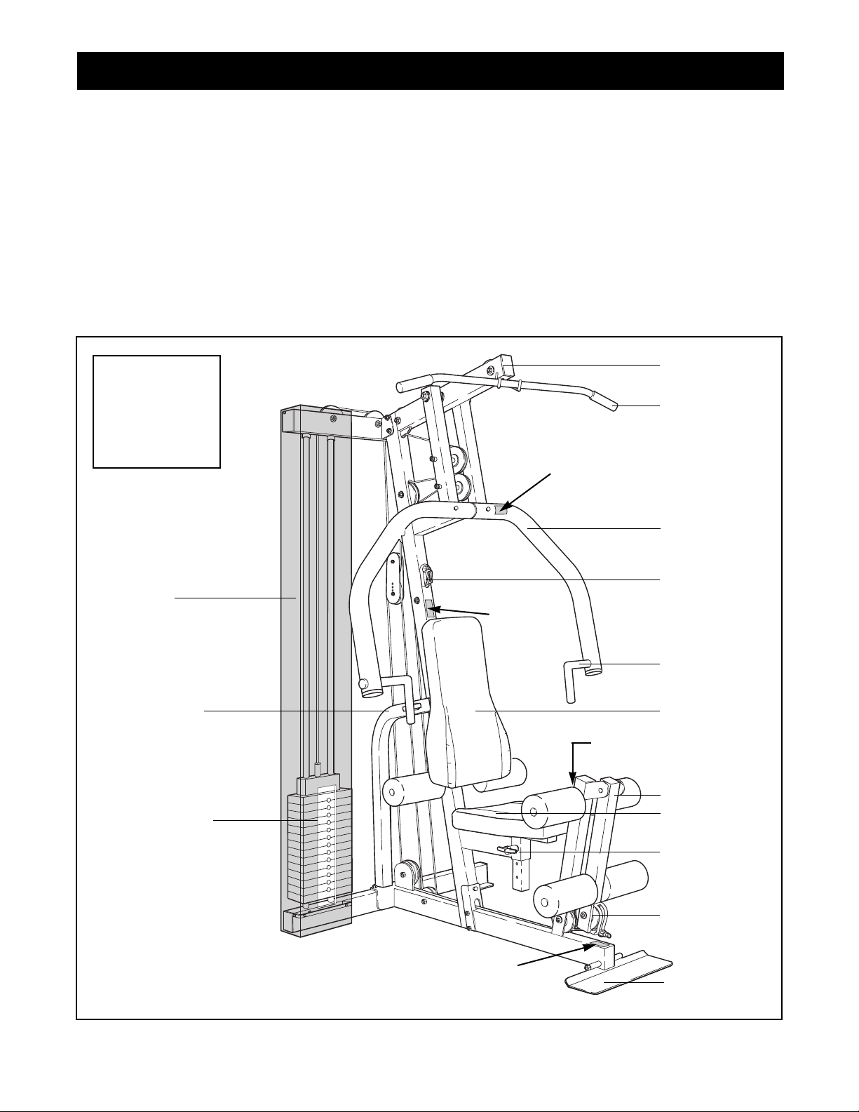
ASSEMBLED
DIMENSIONS:
Height: 81 in.
Width: 44 in.
Length: 62 in.
Low Pulley
Station
Foot Plate
High Pulley
Station
Leg Lever
Press Arm
Shroud
Seat
Backrest
Seat
Adjustment
Tube
Thank you for selecting the versatile NordicTrack
¨
GRT440 Training System. The GRT440 offers a selection of weight stations designed to develop every
major muscle group of the body. Whether your goal is
to tone your body, build dramatic muscle size and
strength or improve your cardiovascular system, the
NordicTrack¨GRT440 will help you to achieve the
results you want.
For your benefit, read this manual carefully before
using the NordicTrack¨GRT440 Training System.
If you have additional questions, please call our
Customer Service Department toll-free at 1-888-8252588, Monday through Friday, 6 a.m. until 6 p.m.
Mountain Time (excluding holidays). To help us assist
you, please note the product model number and serial
number before calling. The model number is
NTSY06990. The serial number can be found on a
decal attached to the NordicTrack¨GRT440 Training
System (see the front cover of this manual).
Please use the drawing below to familiarize yourself with the major parts and how they fit together.
Before You Begin
AB Pulley
Station
Adjustable
Handle
Backrest
Adjustment
Tube
Lat Bar
Weight Stack
Warning Decal No. 1
Warning
Decal
No. 2
Warning Decal No. 1
Warning Decal No. 3
5
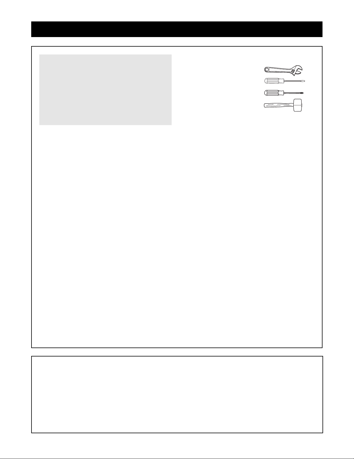
Make sure you have the following tools:
¥ Two (2) adjustable wrenches
¥ One (1) standard screwdriver
¥ One (1) phillips screwdriver
¥ One (1) rubber mallet
¥ You will also need grease or petroleum jelly, a
small amount of soapy water, and clear tape or
masking tape.
Note: Assembly will be more convenient if you have
a socket set, a set of open-end or closed-end
wrenches, or a set of ratchet wrenches.
How to Identify Parts
To help you identify the small parts used in assembly,
we have included a PART IDENTIFICATION CHART
in the center of this manual. Place the chart on the
floor and use it to easily identify parts during each
assembly step. Note: Some small parts may have
been pre-attached. If a part is not in the parts
bag, check to see if it has been pre-attached.
How to Orient Parts
As you assemble the training system, make sure
that all parts are oriented exactly as shown in the
drawings.
Tightening Parts
Tighten all parts as you assemble them, unless
instructed to do otherwise.
Questions?
If you have questions after reading the assembly
instructions, please call our Customer Service
Department toll-free at 1-888-825-2588 Monday
through Friday, 6 a.m. until 6 p.m. Mountain Time.
Assembly Requires Two Persons
For your convenience and safety, assemble the
training system with the help of another person.
Set Aside Enough Time
Due to the many features of the training system,
the assembly process will require about six hours.
By setting aside plenty of time and by deciding to
make the task enjoyable, assembly will go smoothly.
You may want to assemble the training system over
a couple of evenings.
Select a Location for the Training
System
Because of its weight and size, the training system
should be assembled in the location where it will be
used. Make sure that there is enough room to walk
around the training system as you assemble it.
How to Unpack the Box
To make assembly as easy as possible, we have
divided the assembly process into four stages. The
parts needed for each stage are found in individual
bags. Important: Wait until you begin each stage
to open the parts bag for that stage. Place all
parts of the training system in a cleared area and
remove the packing materials. Do not dispose of
the packing materials until assembly is completed.
Assembly
Make Assembly Easier for Yourself!
Everything in this manual is designed to
ensure that the training system can be
assembled successfully by anyone. Before
beginning assembly, make sure to read the
information on this page; this brief introduction will save you much more time than
it takes to read it!
The Four Stages of the Assembly Process
Frame AssemblyÑYou will begin by assem-
bling the base and the uprights that serve as the
skeleton of the training system.
Arm AssemblyÑDuring the second stage you
will assemble the arms and the leg lever.
Cable AssemblyÑDuring this stage you will
attach the cables and pulleys that connect the
arms with each other and with the weights.
Seat AssemblyÑ
This completes the seat and
backrest that support your body while you are
exercising.
6
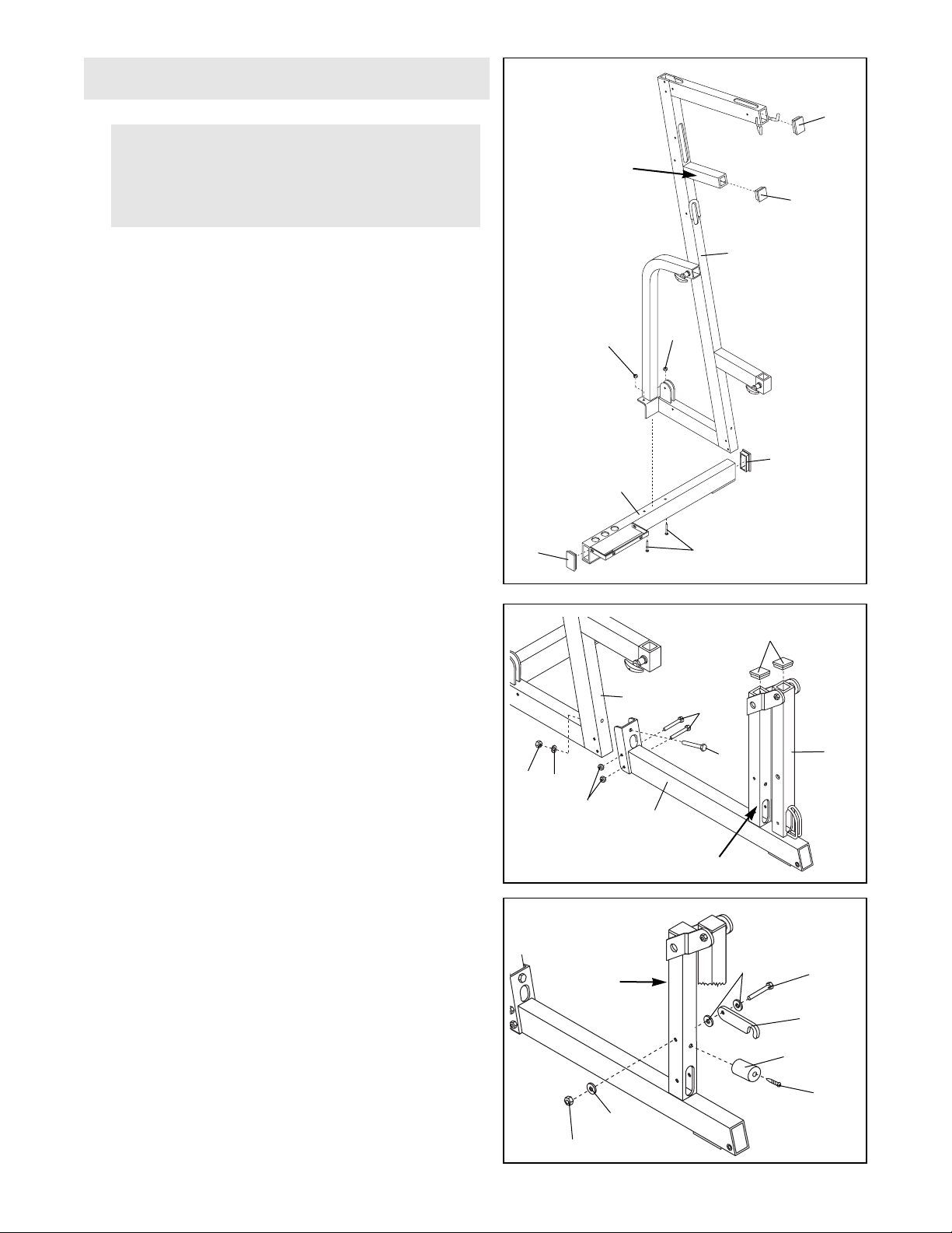
1.
Open the parts bag labeled ÒFRAME ASSEMBLY.Ó
Press a 2Ó Square Inner Cap (33) into the support
tube on the Main Upright (3).
Press a 2Ó x 3Ó Inner Cap (24) into the open end of
the Main Upright (3) and into each end of the
Stabilizer (5).
Attach the Stabilizer (5) to the Main Upright (3) with
two 3/8Ó x 3 3/4Ó Carriage Bolts (52) and two 3/8Ó
Nylon Locknuts (50). Do not tighten the Nylon
Locknuts yet.
1
Frame Assembly
33
24
24
5
50
Support Tube
50
24
3
52
2. Press a 2Ó Square Inner Cap (33) into the upper end
of the front leg on the Base (8) and into the upper
end of the Leg Lever (29).
Line up the bracket on the Base (8) with the holes in
the Main Upright (3). Insert a 3/8Ó x 4Ó Bolt (65)
through the bracket and the Main Upright from the
front. Secure the Bolt with a 3/8Ó Flat Washer (55)
and a 3/8Ó Nylon Locknut (50).
Do not tighten the Nylon Locknut yet.
Insert two 5/16Ó x 3Ó Bolts (78) through the bracket
and the Main Upright (3) from the side. Hand-tighten
two 5/16Ó Nylon Locknuts (21) onto the Bolts.
Do not tighten the Nylon Locknuts yet.
2
65
50
55
78
33
29
8
Front Leg
3
21
3. Attach the Leg Lever Lock (11) to the front leg with a
5/16Ó x 3Ó Bolt (78), three 5/16Ó Flat Washers (80) and
a 5/16Ó Nylon Jamnut (79). Do not overtighten the
Nylon Jamnut; it must be easy to turn the Leg
Lever Lock.
Attach the Leg Lever Bumper (6) to the front leg with
a #10 x 1Ó Tap Screw (7).
78
11
6
7
80
80
79
Front Leg
Before beginning assembly, make sure you
have read and understood the information on
page 5. This brief introduction will save you
much more time than it takes to read it!
3
7
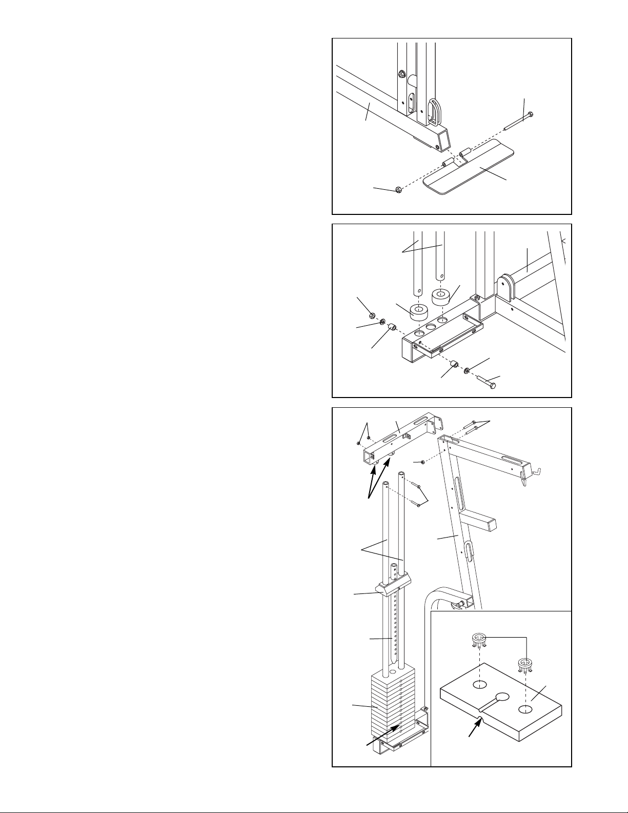
4. Attach the Foot Plate (4) to the Base (8) with a 3/8Ó x
5 1/2Ó Bolt (57) and a 3/8Ó Nylon Locknut (50).
4
57
4
8
50
5. Place two Weight Bumpers (19) over the indicated
holes in the Stabilizer (5).
Insert the two Weight Guides (23) through the Weight
Bumpers (19) and the holes in the Stabilizer (5).
Attach the indicated Weight Guide (23) to the
Stabilizer (5) with a 3/8Ó x 2 1/2Ó Bolt (54), two 3/8Ó
Flat Washers (55), two 5/8Ó x 1/2Ó Pulley Bushings
(42), and a 3/8Ó Nylon Jamnut (63).
5
23
19
55
5
19
63
55
42
42
54
6. IMPORTANT NOTE: If you purchased the optional
weight expansion set, please refer to the userÕs
manual accompanying the set to assemble the
weights. After you have assembled the weights,
refer back to this manual and continue with ÒArm
AssemblyÓ found on the next page.
See the inset drawing. Press two Weight Inserts (77)
into the indicated holes in each Weight (26). Make
sure the large pin groove is oriented as shown.
Slide all of the included Weights (26) onto the two
Weight Guides (23). Make sure the Weights are ori-
ented correctly. The holes must be turned
towards the front of the unit, as shown.
Slide the Top Weight (16) with the pre-attached
Weight Tube (36) onto the Weight Guides (23). The
Weight Tube slides into the hole in the center of the
Weights (26).
Place the Top Frame (1) over the Weight Guides (23),
so the Weight Guides fit into the welded tubes on the
Top Frame.
Align the bracket on the Top Frame (1) with the holes
in the Main Upright (3). Insert two 3/8Ó x 3Ó Bolts (45)
through the holes. Tighten a 3/8Ó Nylon Locknut (50)
onto the lower of the two Bolts. Do not mount a
Locknut on the upper Bolt yet.
Attach the Weight Guides (23) to the Top Frame (1)
with two 3/8Ó x 1 3/4Ó Bolts (60), and two 3/8Ó Nylon
Locknuts (50). Go back and fully tighten all of the
Nylon Locknuts used in steps 1, 2 and 6.
6
45
1
60
50
50
23
16
36
26
Welded
Tubes
Holes
3
77
26
Large Pin
Groove
8
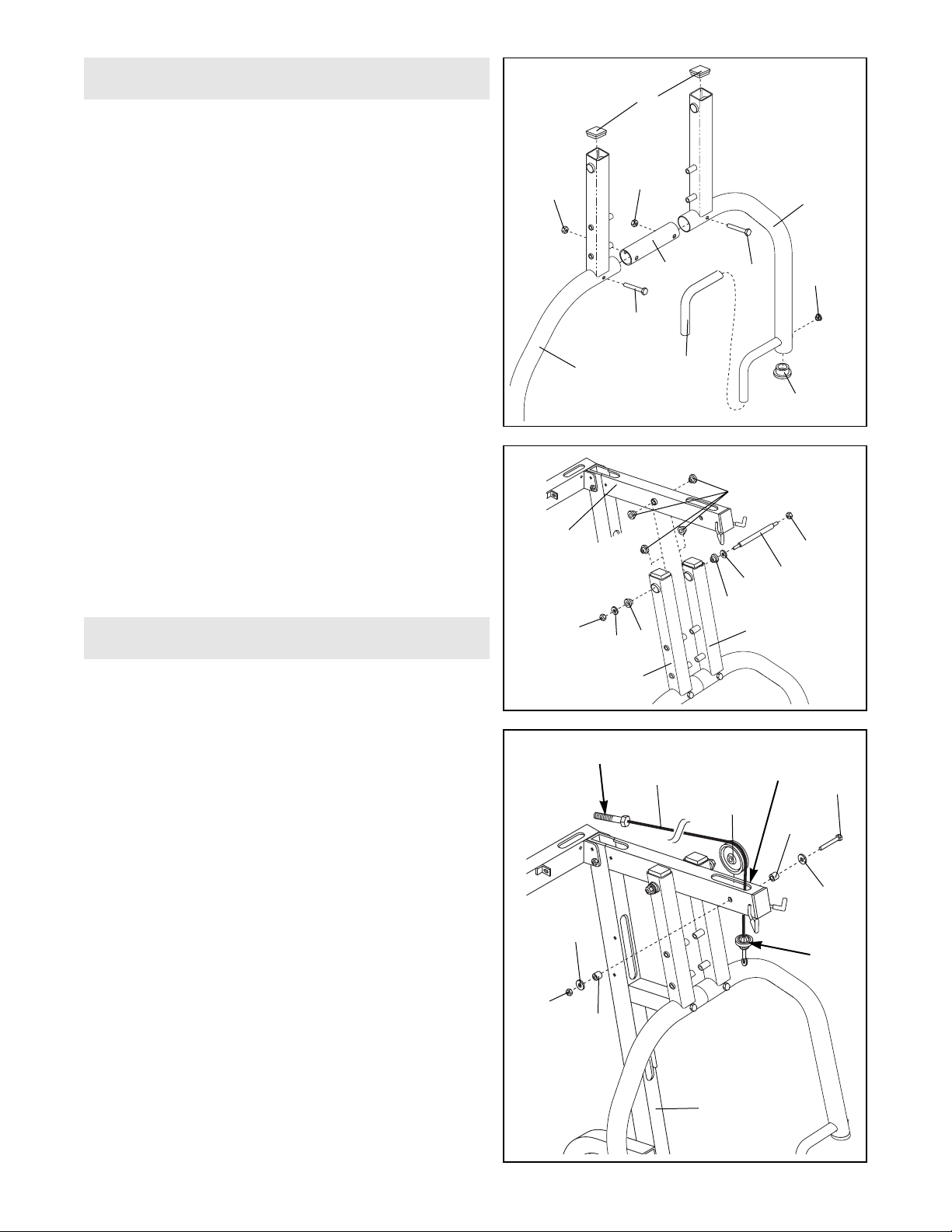
8. Attach the Right and Left Press Arms (46, 82) to the
Main Upright (3) with the Pivot Rod (27), two Large
Washers (53), six 1 1/18Ó x 1/2Ó Flange Bushings
(18), and two 3/8Ó Nylon Jamnuts (63).
Make sure that the Arms (46, 82) are attached
exactly as shown.
86
50
46
33
82
85
50
45
12
20
45
7. Note: Some of the parts used in arm assembly are
located in the parts bag labeled ÒSeat Assembly.Ó
With the help of a second person, join the Right and
Left Press Arms (46, 82) with the Connector Tube
(12). Secure the Arms with two 3/8Ó x 3Ó Bolts (45)
and two 3/8Ó Nylon Locknuts (50).
Press a 2Ó Square Inner Cap (33) into the ends of the
Right and Left Press Arms (46, 82). Press a ?Ó Round
Inner Cap (20) and a ?Ó Round Inner Cap (85) into
each end of the Right and Left Press Arms (46, 82).
Slide a Long Grip (86) onto the indicated ends of the
Right and Left Press Arms (46, 82).
8
53
18
46
63
27
63
18
3
18
82
53
9. Open the parts bag labeled ÒCABLE ASSEMBLY.Ó
Refer to the Cable Diagram on page 16 as you
assemble the Cables.
Identify the High Cable (73). It is approximately 188Ó
long (the shortest Cable), and it has a ball on one
end and a bolt on the other.
Locate the end of the High Cable (73) with the bolt.
Feed this end through the indicated slot in the Main
Upright (3) from below. Feed almost all of the Cable
through the slot.
Slide a 3/8Ó Flat Washer (55) and a 5/8Ó x 1/2Ó Pulley
Bushing (42) onto a 3/8Ó x 2 1/2Ó Bolt (54).
Wrap the High Cable (73) around a 4Ó Pulley (35) and
slide both the Pulley and Cable into the slot in the
Main Upright (3). While holding the Pulley with one
hand, insert the 3/8Ó x 2 1/2Ó Bolt (54) through the
hole in the Main Upright, through the Pulley and
through the other side of the Upright.
Slide a 5/8Ó x 1/2Ó Pulley Bushing (42) and a 3/8Ó Flat
Washer (55) onto the 3/8Ó x 2 1/2Ó Bolt (54). Then
tighten a 3/8Ó Nylon Jamnut (63) onto the Bolt.
9
Cable Assembly
Ball
Bolt
Slot
35
73
55
54
42
55
3
42
63
Arm Assembly
7
 Loading...