

Page 1
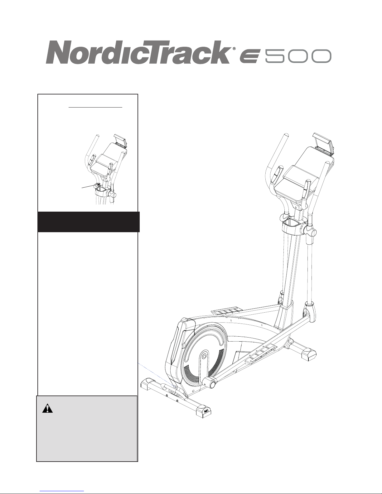
Serial Number
Decal
Model No. NTIVEL57016.0
Serial No.
Write the serial number in the space
above for reference.
USER’S MANUAL
CAUTION
Read all precautions and
instructions in this manual
before using this equipment.
Keep this manual for future
reference.
CUSTOMER SERVICE
UNITED KINGDOM
Call: 0330 123 1045
From Ireland: 053 92 36102
Website: www.iconsupport.eu
E-mail: csuk@iconeurope.com
Write:
ICON Health & Fitness, Ltd.
Unit 1D, The Gateway
Fryers Way, Silkwood Park
OSSETT
WF5 9TJ
UNITED KINGDOM
www.iconeurope.com
Page 2
2
IFIT and PROFORM are registered trademarks of ICON Health & Fitness, Inc. App Store is a trademark of Apple Inc.,
registered in the U.S. and other countries. Android and Google Play are trademarks of Google Inc. The BLUETOOTH®
word mark and logos are registered trademarks of Bluetooth SIG, Inc. and are used under license. IOS is a trademark
or registered trademark of Cisco in the U.S. and other countries and is used under license.
TABLE OF CONTENTS
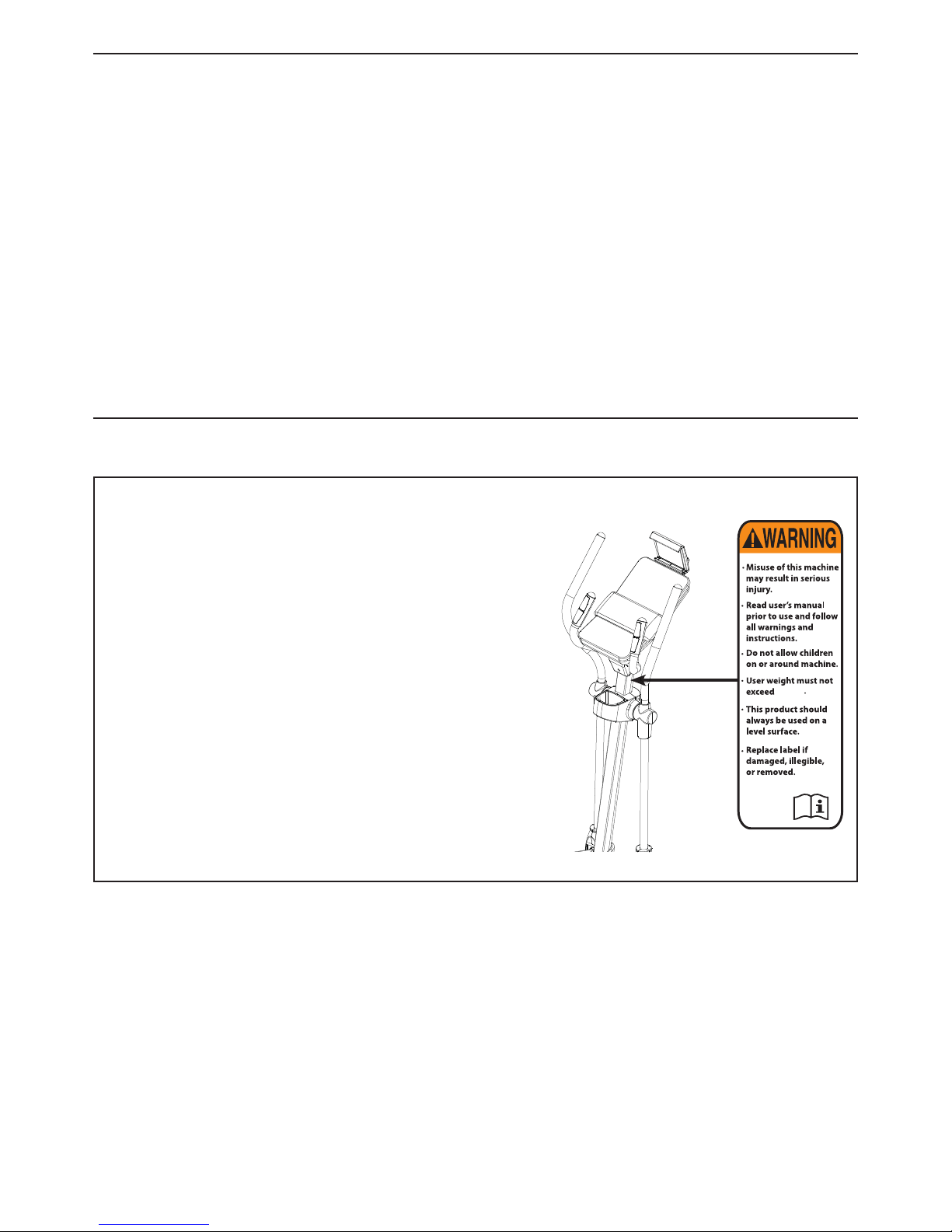
WARNING DECAL PLACEMENT
WARNING DECAL PLACEMENT. . . . . . . . . . . . . . . . . . . . . . . . . . . . . . . . . . . . . . . . . . . . . . . . . . . . . . . . . . . . . . . .2
IMPORTANT PRECAUTIONS ..................................................................3
BEFORE YOU BEGIN ........................................................................4
PART IDENTIFICATION CHART. . . . . . . . . . . . . . . . . . . . . . . . . . . . . . . . . . . . . . . . . . . . . . . . . . . . . . . . . . . . . . . .5
ASSEMBLY ................................................................................6
HOW TO USE THE ELLIPTICAL ...............................................................11
CONSOLE FEATURES ......................................................................12
MAINTENANCE AND TROUBLESHOOTING .....................................................16
EXERCISE GUIDELINES .....................................................................17
PART LIST . . . . . . . . . . . . . . . . . . . . . . . . . . . . . . . . . . . . . . . . . . . . . . . . . . . . . . . . . . . . . . . . . . . . . . . . . . . . . . . .18
EXPLODED DRAWING ......................................................................19
ORDERING REPLACEMENT PARTS. . . . . . . . . . . . . . . . . . . . . . . . . . . . . . . . . . . . . . . . . . . . . . . . . . . . Back Cover
RECYCLING INFORMATION. . . . . . . . . . . . . . . . . . . . . . . . . . . . . . . . . . . . . . . . . . . . . . . . . . . . . . . . . . Back Cover
TECNICHAL SPECIFICATIONS ....................................................... Back Cover
115 Kg
115 Kg
115 Kg
ENGLISH
115 Kg
This drawing shows the location(s) of the warning decal(s). If
a decal is missing or illegible, see the front cover of this
manual and request a free replacement decal. Apply the
decal in the location shown. Note: The decal(s) may not be
shown at actual size.
Page 3

3
IMPORTANT PRECAUTIONS
1. Before beginning any exercise program,
consult your physician. This is especially
important for persons over age 35 or
persons with pre-existing health problems.
2. Use the elliptical only as described in this
manual.
3. It is the responsibility of the owner to ensure
that all users of the elliptical are adequately
informed of all precautions.
4. The elliptical is intended for home use only.
Do not use the elliptical in a commercial,
rental, or institutional setting.
5. Keep the elliptical indoors, away from
moisture and dust. Place the elliptical on a
level surface, with a mat beneath it to protect
the oor or carpet. Make sure that there is at
least 3 ft. (0.9 m) of clearance in the front and
rear of the elliptical and 2 ft. (0.6 m) on each
side.
6. Inspect and properly tighten all parts
regularly. Replace any worn parts
immediately.
7. Keep children under age 12 and pets away
from the elliptical at all times.
8.The elliptical should not be used by persons
weigthing more than 250 lbs. (115 kg).
9. Wear appropriate clothes while exercising;
do not wear loose clothes that could become
caught on the elliptical. Always wear athletic
shoes for foot protection while exercising.
10. Hold the handlebars or the upper body
arms when mounting, dismounting, or using
the elliptical.
11. The pulse sensor is not a medical device.
Various factors may affect the accuracy of
heart rate readings. The pulse sensor is
intended only as an exercise aid in
determining heart rate trends in general.
12. The elliptical does not have a freewheel; the
pedals will continue to move until the
ywheel stops. Reduce your pedaling speed
in a controlled way.
13. Keep your back straight while using the
elliptical; do not arch your back.
14. Over exercising may result in serious injury
or death. If you feel faint or if you experience
pain while exercising, stop immediately and
cool down.
WARNING : To reduce the risk of serious injury, read all important precautions and
instructions in this manual and all warnings on your elliptical before using your elliptical. ICON
assumes no responsibility for personal injury or property damage sustained by or through the
use of this product.
Page 4
4
BEFORE YOU BEGIN
Thank you for selecting the new NORDICTRACK E500
elliptical. The E500 elliptical provides a selection of features designed to make your workouts at home more
effective and enjoyable.
For your benefit, read this manual carefully before you
use the elliptical. If you have questions after reading this
manual, please see the front cover of this manual. To help
us assist you, note the product model number and serial
number before contacting us. The model number and the
location of the serial number decal are shown on the front
cover of this manual.
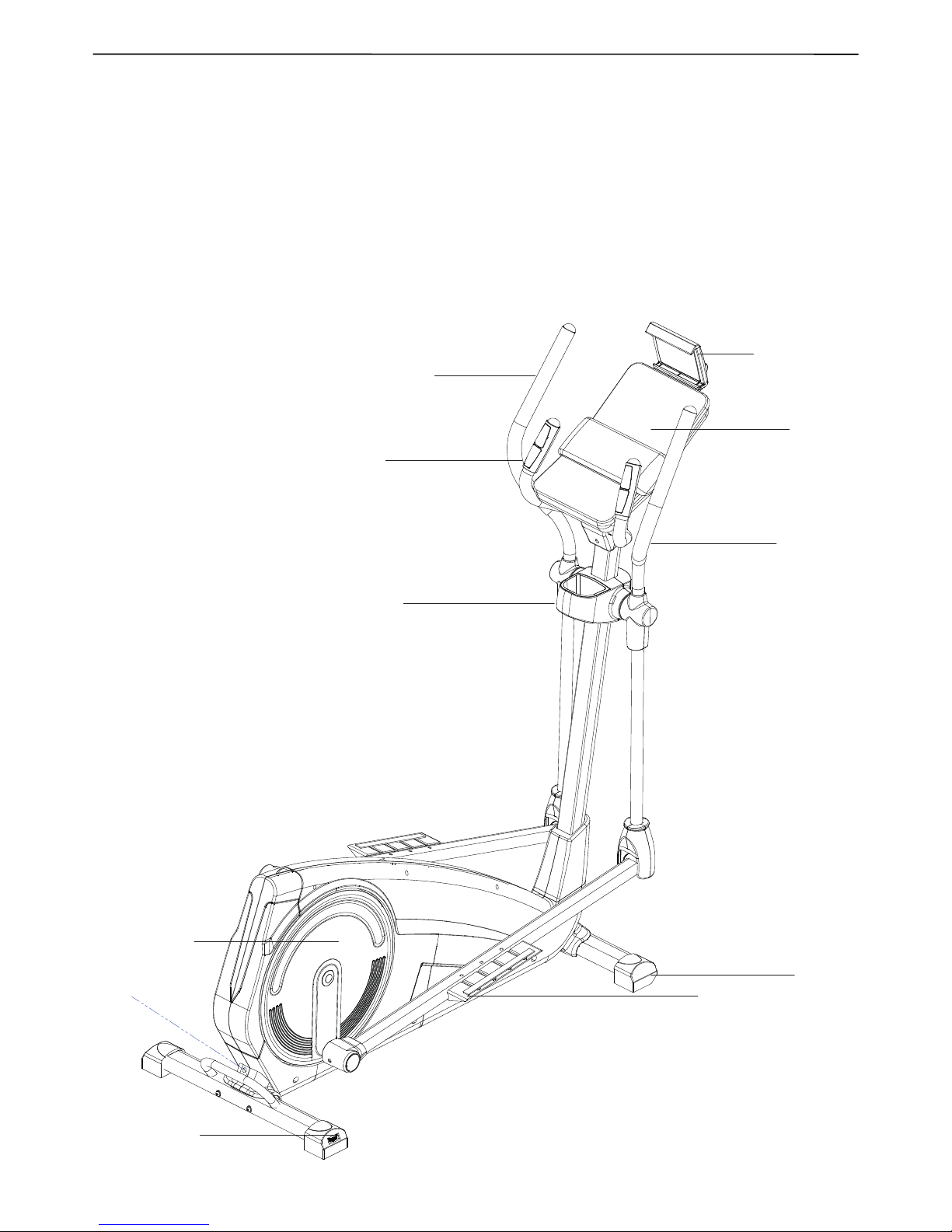
Before reading further, please familiarize yourself with the
parts that are labeled in the drawing below.
Heart Rate Monitor
Upper Body Arm
Tablet Holder
Pedal Disc
*Water bottle is not included
Pedal
Wheel
Console
Water Bottle Holder*
Leveling Foot
Handlebar
Page 5
5
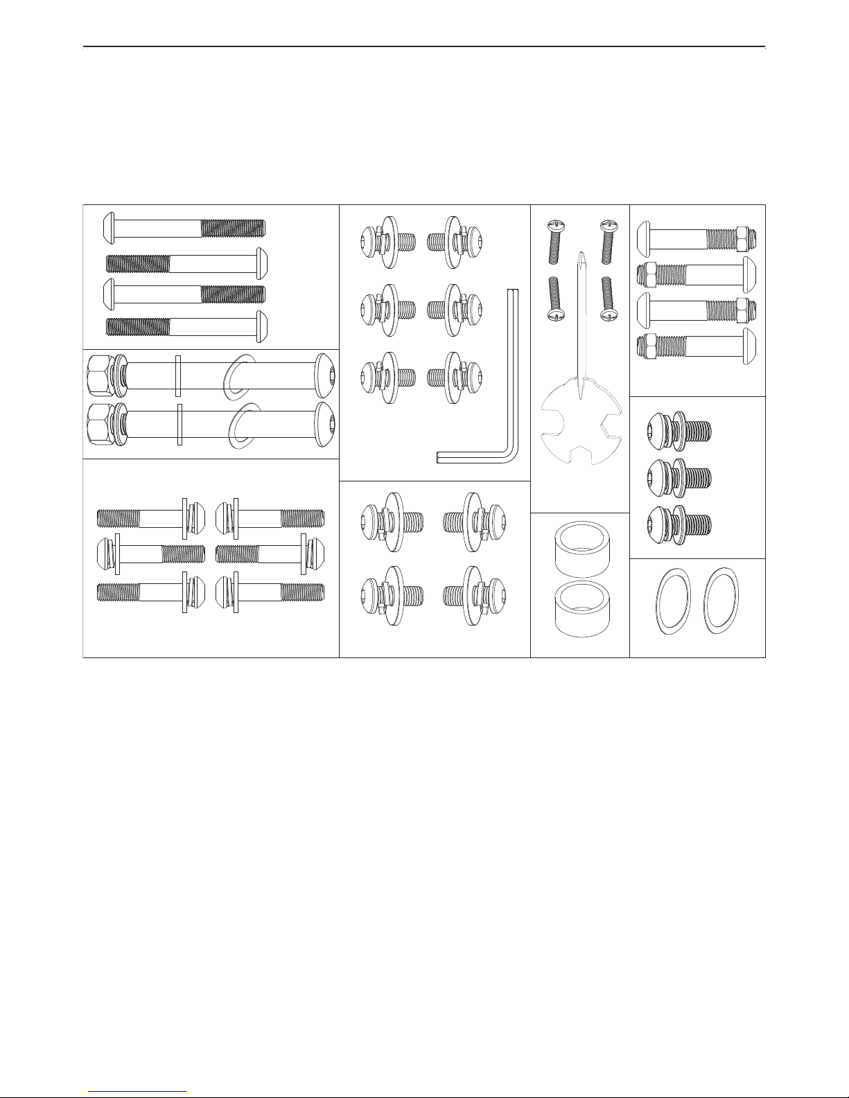
PART IDENTIFICATION CHART
Use the drawings below to identify the small parts needed for assembly. The number in each drawing is the key number of the part, from the PART LIST near the end of this manual. The number following the key number is the quantity
needed for assembly. Note: If a part is not in the hardware kit, check to see whether it has been preassembled.
NO 20*4 NO 21*4
NO 17*6 NO 27*6 NO 33*6
NO 12*3
NO 17*3
NO 16*3
NTIVEL57016.0
NO 35*2
NO 16*4 NO 17*4 NO 18*2 NO 34*2
NO 100*2
NO 97*4
NO 17*6 NO 16*6
NO 27*6 NO 101*1
NO 61*4
NO 103*1
NO 23*2 NO 27*2NO 21*2 NO 24*2
NO 28*2
Page 6
6
60
61
56
93
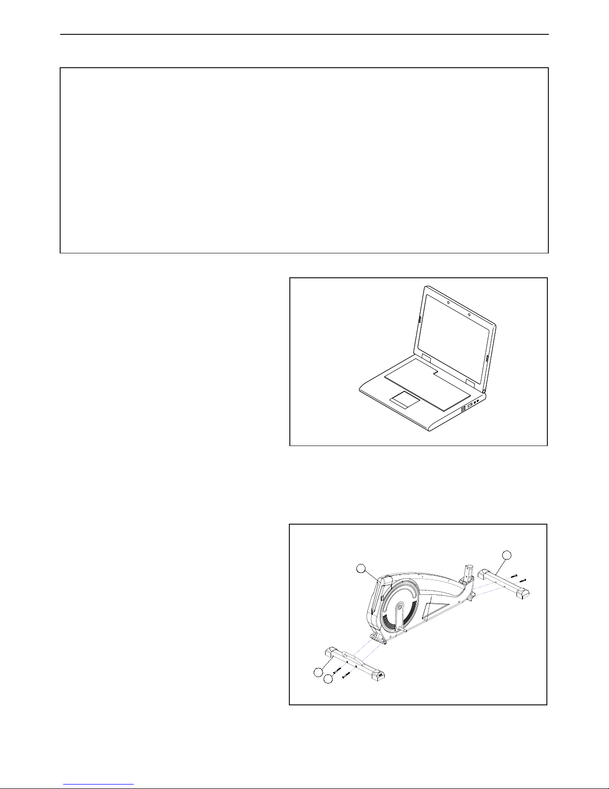
STEP 1
Fasten front stabilizer (93) with two Allen bolts
(61) from the under side of stabilizer. Fasten Rear
stabilizer (60) with two Allen bolts (61).
ASSEMBLY
• Assembly requires two persons.
• Place all parts in a cleared area and remove the
packing materials. Do not dispose of the packing
materials until you nish all assembly steps.
• Left and right parts are marked “L” or “Left” and “R”
or “Right.”
• To identify small parts, see page 18
• As you assemble the exercice bike, use the drawings below to identify small parts. The number in
parentheses below each drawing is the key number
of the part, from the PART LIST near the end of this
manual. The number following the parentheses is
the quantity needed for assembly.
• In addition to the included tool(s), assembly requires
the following tools:
• one adjustable wrench
• one Phillips screwdriver
• Note: If a part is not in the hardware kit, check to
see if it has been preassembled.
Go to www.iconservice.ca/CustomerService/
registration and register your product.
• activates your warranty
• saves you time if you ever need to contact
Customer Service
• allows us to notify you of upgrades and offers
Note: If you do not have internet access, call
Customer Service (see the front cover of this
manual) and register your product.
Page 7

7
96
95
99
17
16
27
94
STEP 2
I. Carefully lift the Handlebar Post (99) until it is vertical. Put the front plastic cover (95) into the Handlebar post
(99). Connect the Upper Computer Cable (96) and the Lower Computer Cable (94).
II. Remove the loosely fitted Allen bolts (16),spring washers (17) and washers ( 27) from the Main Frame and
lower the Handlebar Post (99) into position. Loosely re-fit the Allen Bolt (16), Spring washer (17) and washers (
27) and align the Handlebar Post so it is straigh. Then tighten the Allen bolts fully
Page 8

8
STEP 3
I. Fasten footplate support bars (26R+L) from the crank with coated Allen bolts (16), spring washers (17), washers
(34) and tube spacer (35). Secure the plastic cover (38) onto footplate support bar with screw (39).
II. Slide the upper swing bar Left and Right (14) into the Center Shaft and secure using curved washers (100) two
coated Allen Bolts (16), two washers (18), two spring washer (17).
III. Fit the lower swing bar Left and Right (22) by slotting them into the upper swing bar Left and Right (14) and
loosely fit four Allen bolts (20) and four nut (21).
IV. Fasten footplate support bars (26 R+L) parallel (don’t incline) to the lower swing bars (22 R+L) and secure it
with Allen bolts (23),wave washers (24), washer (28), washer (27) and nuts (21). Then put the plastic cover (29)
onto footplate support bar left and right with screws.
V. Fit the upper swing bar and lower swing bar and secure it four Allen bolts (20) and four nut (21)tighten fully.
Then put the plastic cover (13) onto swing bar left and right with screws,Secure the plastic cover (6) with screws
(5).
13R
13L
22
29
27
39
38
34
35
23
24
16
17
18
96
14L
14R
5
6
28
20
21
21
16
17
100
Page 9

9
96
17
12
1
1
16
STEP 4
Fasten right footplate (30R) with Allen bolts
(33),spring washer (17),washer (27) from the
right footplate support bar and secure it tightly.
Do the same for the left pedal.
STEP 5
Fasten Handle Bar (11) to Handlebar Post and
secure it with Allen Bolt (16), washer (12) and
spring washer (17).
STEP 6
Fasten computer rack (3) to Handlebar Post and
secure it with screws (4)
96
4
3
30L
30
R
33
17
27
Page 10

10
STEP 7
Connect the Upper Computer Cable ( 96) and
two hand pulse cable with the cable on the
back of computer (1).Sit the Computer (1) into
its bracket and secure in place using the four
screws. Attach the Tablet Holder (98) to the
computer (1) with four screws (97): start all the
screws, and then tighten them.
STEP 8
Secure plastic cover onto the handlebar post
with a screw(4)
Note:Before using the machine, make sure all
the screws are fasten tightly
Now your machine is ready for use.
4
3
9
7
98
96
1
2
Page 11

11
HOW TO EXERCISE ON THE ELLIPTICAL
To mount the elliptical exerciser, hold the upper body arms
and step onto the pedal that is in the lowest position. Then,
step onto the other pedal. Push the pedals until they begin
to move with a continuous motion.
Note: The pedal discs can turn in either direction. It is recommended that you move the pedal discs in the direction
shown by the arrow;however, for variety, you may turn the
pedal discs in the opposite direction.
The upper body arms are designed to add upper-body
exercise to your workouts. As you exercise, push and pull
the upper body arms to work your arms, shoulders, and
back. To focus on lower-body exercise, hold the upper
body arms but do not push or pull them as you exercise.
To dismount the elliptical exerciser, wait until the pedals
come to a complete stop.
Note: The elliptical exerciser does not have a free wheel;
the pedals will continue to move until the flywheel stops.
When the pedals are stationary, step off the highest pedal
first. Then, step off the lower pedal.
WHEN YOU ARE FINISHED EXERCISING
If the pedals do not move for several minutes and the buttons are not pressed, the console will turn off and the
display will be reset.
HOW TO USE THE TABLET HOLDER
IMPORTANT: The tab-
let holder is designed
for use with most fullsize tablets. Do not
place any other electronic device or object
in the tablet holder.
To insert a tablet into the
tablet holder, set the bottom edge of the tablet in the tray.
Then, pull the clip over the top edge of the tablet. Make
sure that the tablet is firmly secured in the tablet holder.
Rotate the tablet holder to the desired angle. Reverse
these actions to remove the tablet from the tablet holder.
IMPORTANT: If the elliptical has been exposed to cold
temperatures, allow it to warm to room temperature
before you plug in the power adapter. If you do not do
this, you may damage the console displays or other
electronic components.
Plug the power adapter
into the receptacle on
the frame of the elliptical.
Insert the appropriate plug
adapter into the power
adapter if necessary.
Then, plug the power
adapter into an appropriate outlet that is properly
installed in accordance
with all local codes and
ordinances.
`
HOW TO USE THE ELLIPTICAL
Page 12

12
Contacts
FEATURES OF THE CONSOLE
The advanced console offers an array of features designed
to make your workouts more effective and enjoyable.
When you use the manual mode of the console, you can
change the resistance of the pedals with the touch of a
button.
You can also create custom manual workouts with alternating high and low-intensity intervals.
As you exercise, the console will provide continuous exercise feedback. You can even measure your heart rate using
the handgrip heart rate monitor or a compatible heart rate
monitor. See on the front page for information about
purchasing an optional chest heart rate monitor.
You can also connect your smart device to the console
and use an iFit® app to record and track your workout
information.
The console also offers a selection of onboard workouts.
Each onboard workout automatically changes the resistance of the pedals and prompts you to maintain a target
power output as it guides you through an effective workout.
You can even listen to your favorite workout music or audio
books with the console sound system while you exercise.
To use the manual mode, see page 13. To use an
onboard workout, see page 14.
To use the sound system, see page 15. To connect
your smart device to the console, see page 14. To con-
nect your heart rate monitor to the console, see page
15. To use the settings mode, see page 15.
CONSOLE FEATURES
Page 13

13
HOW TO USE THE MANUAL MODE
1. Begin pedaling or press any button on the console
to turn on the console.
When you turn on the console, the display will turn on.
The console will then be ready for use.
2. Select the manual mode.
Press the Manual Control button to select the manual
mode.
3. Change the resistance of the pedals as desired.
As you pedal, change the resistance of the pedals by
pressing the Quick Resistance increase and decrease
buttons or by pressing one of the numbered Quick
Resistance buttons.
Note: After you press a button, it will take a moment for
the pedals to reach the selected resistance level.
4. Follow your progress with the displays.
The display can show the following workout information:
Calories (flame icon)—This display will show the
approximate number of calories you have burned. When
some onboard workouts are selected, this display will
show the number of calories remaining to be burned for
the workout.
Calories per Hour (Cals/Hr)—This display will show
the approximate number of calories you are burning
per hour.
Distance—This display will show the distance that you
have pedaled in miles (mi) or kilometers (km).
Pulse (BPM)—This display will show your heart rate
in beats per minute (bpm) when you use the handgrip
heart rate monitor or the optional chest heart rate monitor (see step 5).
Pulse Average (BPM AVG)—This display will show
your average heart rate in beats per minute (bpm)
when you use the handgrip heart rate monitor or the
optional chest heart rate monitor (see step 5).
Resistance—This display will show the resistance
level of the pedals for a few seconds each time the
resistance level changes.
RPM—This display will show your pedaling speed in
revolutions per minute (rpm).
RPM Average (RPM AVG)—This display will show
your average pedaling speed in revolutions per minute
(rpm).
Speed—This display will show your pedaling speed in
miles per hour or kilometers per hour. To change the
unit of measurement, press the Standard/Metric button
repeatedly.
Time—When the manual mode is selected, this dis-
play will show the elapsed time. When some onboard
workouts are selected, this display will show the time
remaining in the workout.
Watts—This display will show your approximate power
output in watts.
Average Watts (AVG.)—This display will show your
approximate average power output in watts for the
workout.
Scan Mode and Priority
Mode—The calories and
watts displays will appear in
an alternating cycle (scan mode).
To select either the calories or the
watts display for continuous display (priority mode), press
the increase or decrease button next to the Enter button
repeatedly until the desired display appears. To return to
the scan mode, press the increase button repeatedly until
the word SCAN appears.
Press the Home button to exit the workout and return
to the main menu. If necessary, press the Home button
again.
Press the End/Summary button to end the workout
and view a workout summary. The workout summary
will appear in the displays for several seconds.
Change the volume level
of the console by pressing
the volume increase and
decrease buttons.
5. Measure your heart rate if desired.
You can measure your heart rate using either the
handgrip heart rate monitor or an optional chest heart
rate monitor (see page 15 for information about the
optional chest heart rate monitor). Note: The console is compatible with BLUETOOTH® Smart heart
rate monitors.
Note: If you use both heart rate monitors at the
same time, the chest heart rate monitor will have
priority.
Page 14

14
If there are sheets of plastic on
the metal contacts on the handgrip heart rate monitor, remove
the plastic. To measure your heart
rate, hold the handgrip heart rate
monitor with your palms resting
against the contacts. Avoid mov-
ing your hands or gripping the
contacts tightly.
When your pulse is detected, your heart rate will appear
in the display. For the most accurate heart rate read-
ing, hold the contacts for at least 15 seconds.
6. When you are finished exercising, the console will
turn off automatically.
If the pedals do not move for several seconds, a tone
will sound, the console will pause, and the time will
flash in the display. To resume your workout, simply
resume pedaling.
If the pedals do not move for several minutes and the
buttons are not pressed, the console will turn off and
the display will be reset.
HOW TO USE AN ONBOARD WORKOUT
1. Begin pedaling or press any button on the console
to turn on the console.
When you turn on the console, the display will turn on.
The console will then be ready for use.
2. Select an onboard workout.
To select an onboard workout, press the Calorie button
or the Performance button repeatedly until the desired
workout appears in the display.
When you select an onboard workout, the display will
show the name of the workout and the duration of the
workout or the number of calories to be burned.
The the maximum speed and the maximum resistance
level for the workout will also appear in the display.
3. Begin pedaling to start the workout.
Each workout is divided into one-minute seg-
ments. One resistance level and one target speed is
programmed for each segment. Note: The same resistance level and/or target speed may be programmed
for consecutive segments.
At the end of each segment of the workout, a series of
tones will sound. If a different resistance level and/or
target speed is programmed for the next segment, the
resistance level and/or target speed will appear in the
display for a few seconds to alert you. The resistance
of the pedals will then change.
As you exercise, you will be prompted to keep your
pedaling speed near the target speed for the current
segment. When the words GO FASTER appear in
the display, increase your pace. When the words
SLOW DOWN appear, decrease your pace. When
the words IN RANGE TARGET appear, maintain
your current pace.
IMPORTANT: The target speed is intended only to
provide motivation. Your actual pedaling speed
may be slower than the target speed. Make sure to
pedal at a speed that is comfortable for you.
If the resistance level for the current segment is too high
or too low, you can manually override the setting by
pressing the Quick Resistance buttons. IMPORTANT:
When the current segment of the workout ends,
the pedals will automatically adjust to the resistance level programmed for the next segment.
The workout will continue in this way until the last seg-
ment ends. To pause the workout at any time, stop
pedaling. The time will flash in the display. To resume
the workout, simply resume pedaling.
To end the workout, press the End/Summary button. A
summary of the workout will appear in the displays for
several seconds.
4. Follow your progress with the displays.
See step 4 on page 13,.
5. Measure your heart rate if desired.
See step 5 on page 13,
6. When you are finished exercising, the console will
turn off automatically.
See step 6 on page 14.
HOW TO CONNECT YOUR SMART DEVICE TO THE
CONSOLE
The console supports BLUETOOTH connections to smart
devices via the iFit app and to compatible heart rate
Contacts
Page 15

15
monitors. Note: Other BLUETOOTH connections are not
supported.
1. Download and install the iFit app on your smart
device.
On your iOS® or Android™ smart device, open the App
Store℠ or the Google Play™ store, search for the free
iFit app, and then install the app on your smart device.
Make sure that the BLUETOOTH option is enabled
on your smart device.
Then, open the iFit app and follow the instructions to
set up an iFit account and customize settings.
2. Connect your smart device to the console.
Follow the instructions in the iFit app to connect your
smart device to the console.
When a connection is established, the LED on the con-
sole will flash blue. Press the Bluetooth Smart button
on the console to confirm the connection; the LED on
the console will then turn solid blue.
3. Record and track your workout information.
Follow the instructions in the iFit app to record and
track your workout information.
4. Disconnect your smart device from the console if
desired.
To disconnect your smart device from the console,
press and hold the Bluetooth Smart button on the console for 5 seconds.
Note: All BLUETOOTH connections between the con-
sole and other devices (including any smart devices,
heart rate monitors, and so forth) will be disconnected.
HOW TO CONNECT YOUR HEART RATE MONITOR
TO THE CONSOLE
The console is compatible with all BLUETOOTH Smart
heart rate monitors.
To connect your BLUETOOTH Smart heart rate monitor
to the console, press the Bluetooth Smart button on the
console. When a connection is established, the LED on
the console will flash red twice.
Note: If there is more than one compatible heart rate monitor near the console, the console will connect to the heart
rate monitor with the strongest signal.
To disconnect your heart rate monitor from the console,
press and hold the Bluetooth Smart button on the console
for 5 seconds.
Note: All BLUETOOTH connections between the console
and other devices (including any smart devices, heart rate
monitors, and so forth) will be disconnected.
HOW TO USE THE SOUND SYSTEM
To play music or audio books through the console sound
system while you exercise, plug a 3.5 mm male to 3.5 mm
male audio cable (not included) into the jack on the console and into a jack on your personal audio player; make
sure that the audio cable is fully plugged in. Note: To
purchase an audio cable, see your local electronics
store.
Next, press the play button on your personal audio player.
Adjust the volume level using the
volume increase and decrease
buttons on the console or the
volume control on your personal
audio player.
THE OPTIONAL CHEST HEART RATE MONITOR
Whether your goal is to burn fat or to strengthen your
cardiovascular system,
the key to achieving the
best results is to maintain
the proper heart rate during your workouts. The
optional chest heart rate
monitor will enable you to
continuously monitor your
heart rate while you exercise, helping you to reach your
personal fitness goals. To purchase a chest heart rate
monitor, please see the front cover of this manual.
Note: The console is compatible with all BLUETOOTH®
Smart heart rate monitors
HOW TO CHANGE CONSOLE SETTINGS
1. Select the settings mode.
To select the settings mode, press the Settings button.
The settings information will appear in the display.
2. Navigate the settings mode.
While the settings mode is selected, the display will
show several optional screens. Press the increase and
decrease buttons near the Enter button repeatedly to
select the desired optional screen.
The lower section of the display will show instructions
for the selected screen. Make sure to follow the
instructions shown in the lower part of the display.
3. Change settings as desired.
Units—The currently selected unit of measurement
will appear in the display. To change the unit of measurement, press the Enter button repeatedly. To view
distance in miles, select ENGLISH. To view distance in
miles, select ENGLISH. To view distance in kilometers,
select METRIC.
Page 16

16
Contrast Level—The currently selected contrast level
will appear in the display. Press the Quick Resistance
increase and decrease buttons to adjust the contrast
level.
Usage Information—The display will show the total
number of hours that the elliptical has been used and
the total distance (in miles or kilometers) that has been
pedaled on the elliptical.
4. Exit the settings mode.
Press the Settings button to exit the settings mode.
MAINTENENCE AND TROUBLESHOOTING
MAINTENANCE
Regular maintenance is important for optimal performance
and to reduce wear. Inspect and properly tighten all parts
each time the elliptical is used. Replace any worn parts
immediately.
To clean the elliptical, use a damp cloth and a small amount
of mild soap. IMPORTANT: To avoid damage to the con-
sole, keep liquids away from the console and keep the
console out of direct sunlight.
CONSOLE TROUBLESHOOTING
If the console does not display your heart rate when you
hold the handgrip heart rate monitor, or if the displayed
heart rate appears to be too high or too low, see step 5 on
page 11,.
If a replacement power adapter is needed, call the
telephone number on the cover of this manual.
IMPORTANT: To avoid damaging the console, use only
a manufacturer-supplied regulated power adapter.
Page 17

17
EXERCISE GUIDELINES
These guidelines will help you to plan your exercise program. For detailed exercise information, obtain a reputable
book or consult your physician. Remember, proper nutrition and adequate rest are essential for successful results.
EXERCISE INTENSITY
Whether your goal is to burn fat or to strengthen your cardiovascular system, exercising at the proper intensity is
the key to achieving results. You can use your heart rate
as a guide to find the proper intensity level. The chart
below shows recommended heart rates for fat burning and
aerobic exercise.
To find the proper intensity level, find your age at the bottom of the chart (ages are rounded off to the nearest ten
years). The three numbers listed above your age define
your “training zone.” The lowest number is the heart rate
for fat burning, the middle number is the heart rate for
maximum fat burning, and the highest number is the heart
rate for aerobic exercise.
Burning Fat—To burn fat effectively, you must exercise at
a low intensity level for a sustained period of time. During
the first few minutes of exercise, your body uses carbohydrate calories for energy. Only after the first few minutes
of exercise does your body begin to use stored fat calories
for energy. If your goal is to burn fat, adjust the intensity
of your exercise until your heart rate is near the lowest
number in your training zone. For maximum fat burning,
exercise with your heart rate near the middle number in
your training zone.
Aerobic Exercise—If your goal is to strengthen your cardiovascular system, you must perform aerobic exercise,
which is activity that requires large amounts of oxygen for
prolonged periods of time. For aerobic exercise, adjust the
intensity of your exercise until your heart rate is near the
highest number in your training zone.
WORKOUT GUIDELINES
Warming Up—Start with 5 to 10 minutes of stretching and
light exercise. A warm-up increases your body temperature, heart rate, and circulation in preparation for exercise.
Training Zone Exercise—Exercise for 20 to 30 minutes
with your heart rate in your training zone. (During the first
few weeks of your exercise program, do not keep your
heart rate in your training zone for longer than 20 minutes.)
Breathe regularly and deeply as you exercise; never hold
your breath.
Cooling Down—Finish with 5 to 10 minutes of stretching. Stretching increases the flexibility of your muscles and
helps to prevent post-exercise problems.
EXERCISE FREQUENCY
To maintain or improve your condition, complete three
workouts each week, with at least one day of rest between
workouts. After a few months of regular exercise, you
may complete up to five workouts each week, if desired.
Remember, the key to success is to make exercise a regular and enjoyable part of your everyday life.
WARNING: Before beginning this
or any exercise program, consult your physician.
This is especially important for persons over age
35 or persons with pre-existing health problems.
The heart rate monitor is not a medical device.
Various factors may affect the accuracy of heart
rate readings. The heart rate monitor is intended
only as an exercise aid in determining heart rate
trends in general.
Page 18

18
Key No. Qty. Description Key No. Qty. Description
Note: Specifications are subject to change without notice. For information about ordering replacement parts, see the
back cover of this manual. *These parts are not illustrated.
PART LIST
Model No. NTIVEL57016.0
1 1 Computer
2 4 Self- tapping screw M4*16
3 1 Computer rack
4 3 Screw M5-0.8*15
5 8 Self- tapping screw M4*20
6 1 Central shaft cover
7 1 Hand pulse cable 650mm
8 4 Screw M2.5-0.45*33
9 4 End Cap Φ32*36
10 2 Hand pulse gripsΦ32
11 1 Handlebar welding
12 3 Washer Φ8*Φ16*1.5T
13L 1 Center Shaft Plastic Cover L
13R 1 Center Shaft Plastic Cover R
14L 1 Handrail welding L
14R 1 Handrail welding R
15 2 Foam Φ32*3T*510mm
16 13 Allen Bolt M8-1.25*20
17 19 Spring Washer Φ8
18 2 Washer Φ8*Φ32*3T
19 4 Powder Metallurgy 38*17*15T
20 4 Allen Bolt M8-1.25*43
21 6 Nut M8
22 2 Lower Swing Bar welding
23 2 Allen Bolt M8-1.25*86
24 4 Wave Washer Φ10*Φ15*0.5T
25 4 Iron-based Powders
Φ32*Φ10*14.5T
26L 1 Footplate Support Bar L
26R 1 Footplate Support Bar R
27 14 Washer Φ8*Φ19*2T
28 2 Washer Φ10*Φ19*2T
29 2 Plastic Cover
30L 1 Footplate L
30R 1 Footplate R
31 2 Eva Foamed Tapes 20*250*3mm
32 2 Eva Foamed Tapes 20X40X3
33 6 Allen Bolt M8-1.25*45 5mm
34 2 Washer Φ8*Φ24*2T ucp
35 2 Tube Spacer Φ17.5*Φ22*12mm
36 2 C-Sharp Clip Φ40
37 2 Bearing 2203-2RS
38 2 Crank Connect Cover
39 2 Screw M5*7.5
40 6 Drill Screw M5*20
41 1 Plastic Cover
42L 1 Chain Cover L
42R 1 Chain Cover R
43 3 Plastic screw
44 11 Drill Screw M5*15
45 2 Crank plug
46 2 Round Cover
47 2 Flange Screw M10-1.25*10T
48 2 Cross
49 8 Self- tapping screw M4.5*15
50 2 Axle Cap
51 1 Nut M10*1.25*6T
52 2 Chain Adjuster Set
53 1 C-Sharp Clip Φ20
54 1 Washer Φ20*Φ25*2.0T
55 1 Sensor with Cable1000mm
56 1 Main Frame
57 1 DC Cable 1000mm
58 2 Eva Foamed Tapes 60*90*2
59 2 Rear End Cap
60 1 Rear stabilizer
61 4 Allen Bolt M8-1.25*92mm
62 2 Bearing 6004-2RS
63 3 Washer Φ20*Φ25*1.0T
64 1 Wave Washer Φ20*Φ25*0.5T
65 1 Belt Wheel Φ440*20.2
66 1 Round Metal Plate welding
67 4 Screw M8-1.25*12
68 1 Belt 690J6
69 5 Self- tapping screw M4.5*25
70 10 Magnet 40*25*10
71 3 Washer Φ6*Φ14*1.5T
72 2 Allen Bolt M6*15
73 2 spring Φ6
74 1 Rotating spindle Φ12*33.2
75 1 Magnet Steel Frame
76 1 Nut M10-1.25*10T
77 1 Idler wheel mandrel Φ10*42mml
78 1 Idler wheel Φ37*20.5L
79 1 Washer 8*16*2T
80 2 C-Sharp Clip Φ10
81 1 Nut M6
82 1 Spring Φ1*12
83 1 Screw M6*80
84 2 Nut M6
85 1 Fly Wheel Φ300*34
86 2 Bearing 6000-2RS
87 1 Mandrel M10*1.25
88 2 Nut M10*1.25
89 1 Flange Screw M10*1.25*10T
90 1 Wire 1000mm
91 1 Motor
92L 1 Front End Cap L
92R 1 Front End Cap R
93 1 Front stabilizer
94 1 Lower computer cable 800mm
95 1 Front Plastic Cover
96 1 Upper computer cable 1250mm
97 4 Screw M4-0.7*15
98 1 Tablet Holder
99 1 Handlebar Post
100 2 Wave Washer Φ17*Φ25*0.5T
101 1 Allen key wrench 5mm
102 1 Adaptor
103 1 Combination Wrench
Page 19

19
EXPLODED DRAWING
Item.101
Item.103
Item.102
1
7
8
3
4
9
10
11
2
5
6
13L
14L
14R
15
13R
16
17
18
19
20
22
21
29
27
30L
31
40
41
42L
44
45
46
48
49
50
51
52
55
56
57
103
59
60
61
53
54
62
64
65
66
67
68
42R
26R
43
47
73
75
74
71
70
72
81
85
86
87
88
89
82
83
84
80
78
77
76
90
91
92R
93
92L
94
95
99
96
100
12
30R
69
63
36
37
35
39
38
33
23
24
25
26L
34
97
98
28
58
32
79
Page 20

Part No. M01231 Printed in China © 2016 ICON Health & Fitness, Inc.
To order replacement parts, please see the front cover of this manual. To help us assist you, be prepared to provide the
following information when contacting us:
• the model number and serial number of the product (see the front cover of this manual)
• the name of the product (see the front cover of this manual)
• the key number and description of the replacement part(s) (see the PART LIST and the EXPLODED DRAWING near
the end of this manual)
ORDERING REPLACEMENT PARTS
This electronic product must not be disposed of in municipal waste. To preserve
the environment, this product must be recycled after its useful life as required
by law.
Please use recycling facilities that are authorized to collect this type of waste in your
area. In doing so, you will help to conserve natural resources and improve European
standards of environmental protection. If you require more information about safe and
correct disposal methods, please contact your local city office or the establishment
where you purchased this product.
IMPORTANT RECYCLING INFORMATION FOR E. U. CUSTOMERS
TECHNICAL SPECIFICATIONS
Product dimensions : (L x W x H) : 172 x 61 x 163 cm
Product Weight: 59,5 KG
NTIVEL57016.0_M04230_SP
 Loading...