

Page 1
0 C C
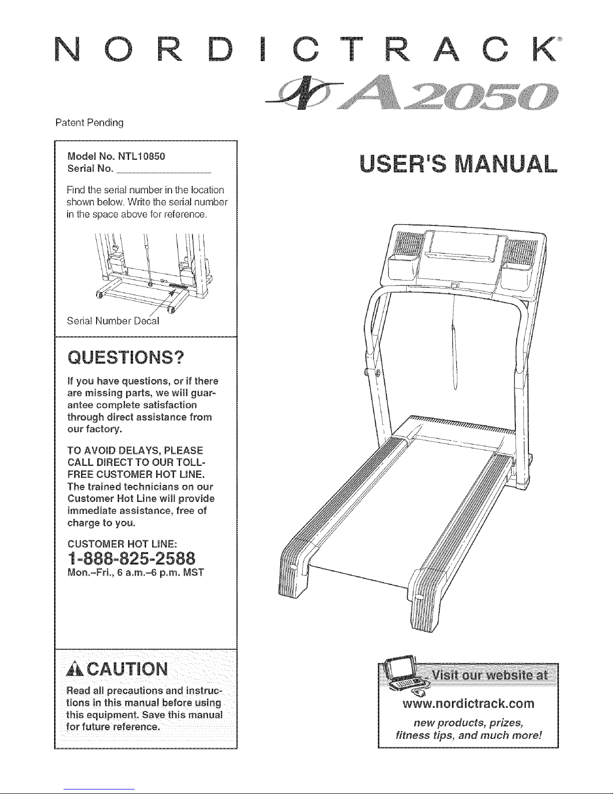
Patent Pending
Mode! No. NTL10850
Seda! No.
Find the seriaUnumber in the Uocation
shown beUow,Write the seriaUnumber
in the space above for reference,
'S
SeriaUNumber DecaU
If you have questions, or if there
are missing parts, we wilt guar-
antee complete satisfaction
through direct assistance from
our factory.
TO AVOID DELAYS, PLEASE
CALL DIRECT TO OUR TOLL-
FREE CUSTOMER HOT LINE.
The trained technicians on our
Customer Hot Line will provide
immediate assistance, free of
charge to you.
CUSTOMER HOT LINE:
/
1-888-825-2588
Mon.-Fd., 8 a.m.-8 p.m. MST
Ac CAUTION
Read all precautions and inetru co
tions in this manual before using
this equipment. Save this manual
for future reference.
www.nordictrack.com
new products, prizes,
fitness tips, and much more r.
Page 2

©T C
TABLE OF CONTENTS
iMPORTANT PRECAUTIONS ................................................................. 3
BEFORE YOU BEGIN ....................................................................... 5
ASSEMBLY ............................................................................... 6
OPERATHON AND ADJUSTMENT ............................................................ 10
HOW TO FOLD AND MOVE THE TREADMHLL .................................................. 24
TROUBLESHOOTHNG ...................................................................... 26
CONDHTHONHNGGUHDELHNES ............................................................... 28
PART LiST ............................................................................... 30
ORDERING REPLACEMENT PARTS .......................................................... 31
LHMHTEDWARRANTY ............................................................... Back Cover
Note: An EXPLODED DRAWING is attached in the center of this manual,
NordicTrack is a registered trademark of HCONHP,Hnc,
2
Page 3

iMPORTANT PRECAUTIONS
WAR NiNG: Toreducethe.skofbume,fire,electricshock,orinjurytoperson.,readthe
following important precautions and information before operating the treadmill.
1. it is the responsibility of the owner to ensure 12. Failure to use a properly functioning surge
that all users of this treadmill are adequately
informed of all warnings and precautions.
2. Use the treadmill only as described.
3. Place the treadmill on a level surface, with at
least eight feet of clearance behind it and two
feet on each side. Do not place the treadmill
on any surface that blocks air openings. To
protect the floor or carpet from damage, pJace 14. Never move the walking belt while the power
a mat under the treadmill, is turned off. Do not operate the treadmill if
4. Keep the treadmill indoors, away from tools= treadmill is not working properly. (See
ture and dust. Do not put the treadmill in a BEFORE YOU BEGIN on page 5 if the tread=
garage or covered patio, or near water, mill is not working properJy.)
5. Do not operate the treadmill where aerosol 15. Never start the treadmHJ while you are stand-
products are used or where oxygen is being ing on the walking belt. Always hoJd the
administered, handrails while using the treadmill.
8=
Keep children under the age of 12 and pets
away from the treadmHJ at aH times.
7_
The treadmill should not be used by persons
weighing more than 300 pounds.
Never allow more than one person on the
treadmill at a time.
9=
Wear appropriate exercise clothes when
using the treadmill. Do not wear loose clothes
that could become caught in the treadmill.
Athletic support clothes are recommended for
both men and women. Always wear athletic
shoes. Never use the treadmill with bare feet,
wearing only stockings, or in sandals.
10. When connecting the power cord (see page 1O)....
plug the power cord into a surge suppressor
(not included) and plug the surge suppressor
into a grounded circuit capable of carrying 15
or more amps. No other appliance should be on
the same circuit. Do not use an extension cord.
11. Use only a single°outlet surge suppressor that
meets aH of the specifications described on
page t0. To purchase a surge suppressor, see
your Jocal NordicTrack dealer or call 1-888-
825-2588 and order part number 146148.
suppressor couJd result in damage to the con-
trol system of the treadmill. If the control sys-
tem is damaged, the walking belt may change
speed, accelerate, or stop unexpectedly,
which may resuJt in a fall and serious injury.
13.
Keep the power cord and the surge suppres=
sot away from heated surfaces.
the power cord or pJug is damaged, or if the
16. The treadmill is capable of high speeds.
Adjust the speed in small increments to avoid
sudden jumps in speed.
17. The puJse sensor is not a medicaJ device.
Various factors, including the user's move-
ment, may affect the accuracy of heart rate
readings. The puJse sensor is intended on] y
as an exercise aid in determining heart rate
trends in general.
18. Never leave the treadmill unattended while it
is running. Always remove the key, unplug the
power cord, and switch the reset!off ci rcuit
breaker to the off position when the treadmill
is not in use. (See the drawing on page 5 for
the location of the reset/off circuit breaker.)
19. Do no_ attempt to raise, lower, or move the
treadmill until it is properly assembled. (See
ASSEMBLY on page 6, and HOW TO FOLD
AND MOVE THE TREADMILL on page 24.) You
must be able to safeJy lift 45 pounds (20 kg) to
raise, tower, or move the treadmill
20. Do not change the incline of the treadmill by
placing objects under the treadmill.
21. When folding or moving the treadmill make
sure that the storage latch is fully cJosed.
3
Page 4
22. When using iFIT.com CDs and videos, an 25. inspect and properly tighten all parts of the
eJectronic "chirping" sound will aJert you treadmill reguJarly.
when the speed and/or incJine of the treadmHJ
is about to change. Always listen for the 26. Never insert or drop any object into any
"chirp" and be prepared for speed and/or in-
cline changes, mnsome instances, the speed
and/or incline may change before the per- unpJug the power
sonal trainer describes the change, cord immediateJy after use, before cleaning
the treadmill, and before performing the main-
23. When using iFmT.com CDs and videos, you
can manually override the speed and incline
settings by pressing the speed and incline
buttons. However, when the next "chirp" is
heard, the speed and/or incline will change to
the next settings of the CD or video program.
24. Always remove iFIT.com CDs and videos from
tenance and adjustment procedures de-
scribed in this manual Never remove the
motor hood unless instructed to do so by an
authorized service representative. Servicing
other than the procedures in this manuaJ
should be performed by an authorized service
representative onJy.
your CD player or VCR and disconnect your 28. The treadmill is intended for in-home use
MP3 player when you are not using them.
only. Do not use the treadmill in any commer_
ciak rentaJ, or institutional setting.
AWARNmNG: Beforebeginningthisoranyexeroiseprogram,coneultyourphysician.This
is especially important for persons over the age of 35 or persons with pre=e×isting health problems.
Read all instructions before using, mCONassumes no responsibility for pereonaJ injury or property
damage sustained by or through the use of this product.
SAVE THESE INSTRUCTIONS
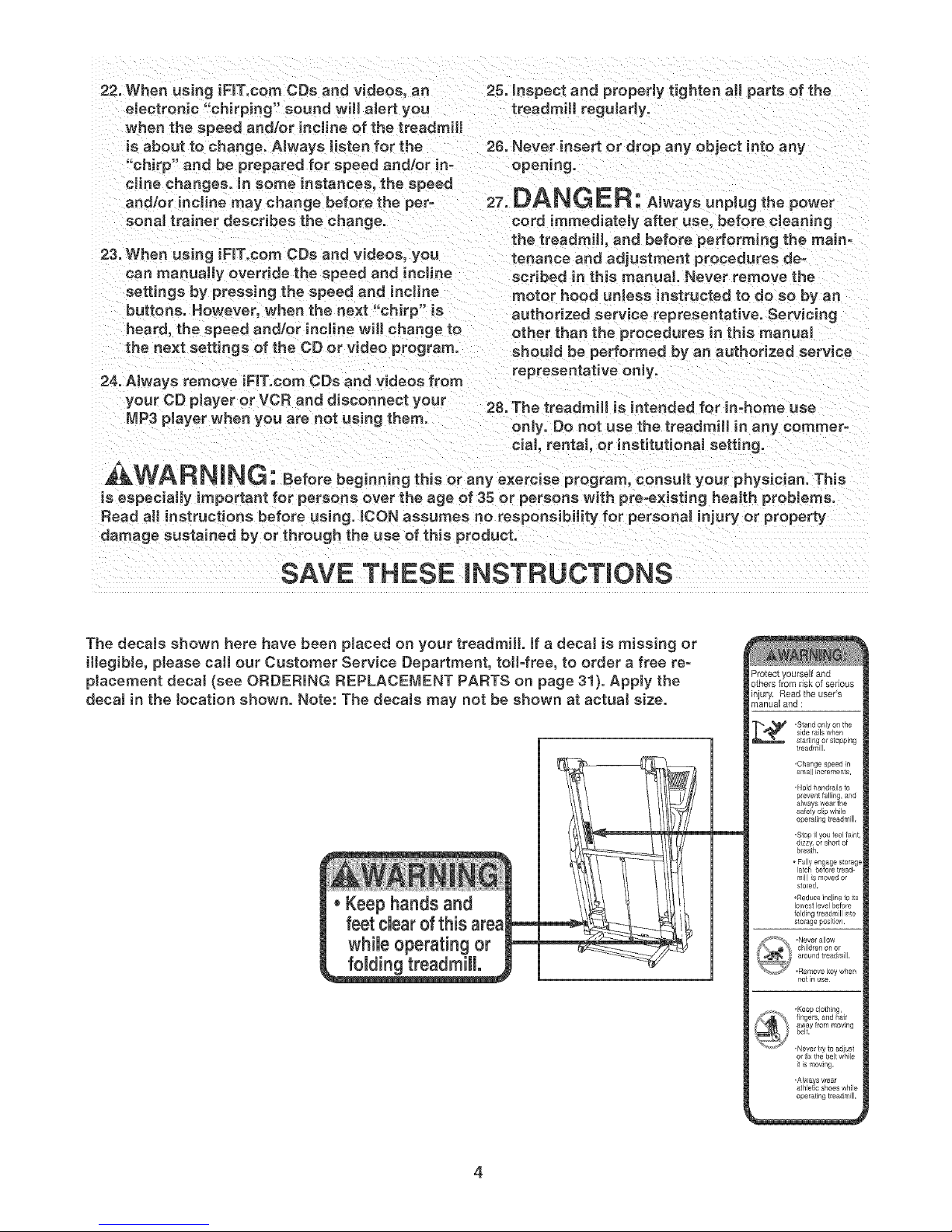
The decaJs shown here have been placed on your treadmill, ff a decal is missing or
illegible, please call our Customer Service Department, toll-free, to order a free re-
placement decal (see ORDERING REPLACEMENT PARTS on page 31). Apply the
decal in the tocation shown. Note: The decaJs may not be shown at actuaJ size.
treadmill.
Protect yourself and
others from risk of serious
injury. Read the user's
manual and :
side rails when
___ -Stand onlyon the
,Change speed in
small increments,
,Hold handlail_ to
safety clip while
opemling treadmill,
-Slop g you feel faint,
dizzy_or short of
bl_ath.
F_lly engage storagt
latch before tread_
mill _smoved or
sfoled,
•Reduce _ncline to i_s
lowest level before
folding treadmill into
sfo_age position¸
,Never allow
children on or
around treadmill,
•Remove key when
not in use
it is moving,
,Always we_r
athletic shoes while
operagng treadmill.
Page 5

BEFORE YOU BEGIN
Thank you for selecting the revolutionary NordicTrack _>
A2050 treadmill, The A2050 treadmill offers a selection
of features designed to make your workouts at home
more enjoyable and effective, And when you're not ex-
ercising, the unique A2050 treadmill can be folded up,
requiring less than half the floor space of other tread°
mills,
For your benefit, read this manual carefully before
using the treadmill, if you have questions after read-
ing this manual, please call our Customer Service
Book Holder
Fan
Accessory Tray
Handrail
Department toll-free at 1°888°825°2588, Monday
through Friday, 6 a,m, until 6 p,m, Mountain Time (ex-
cluding holidays), To help us assist you, please note
the product model number and serial number before
calling, The model number of the treadmill is
NTL10850, The serial number can be found on a decal
attached to the treadmill (see the front cover of this
manual for the location),
Before reading further, please familiarize yourself with
the parts that are labeled in the drawing below,
Console
Fan
Pulse Sensor
Latch Knob
Walking Belt
Foot Rail
Rear Roller
Adjustment Bolts --
Key/Clip
Reset/Off
Circuit Breaker
Power Cord
Cushioned Walking Platform
Page 6
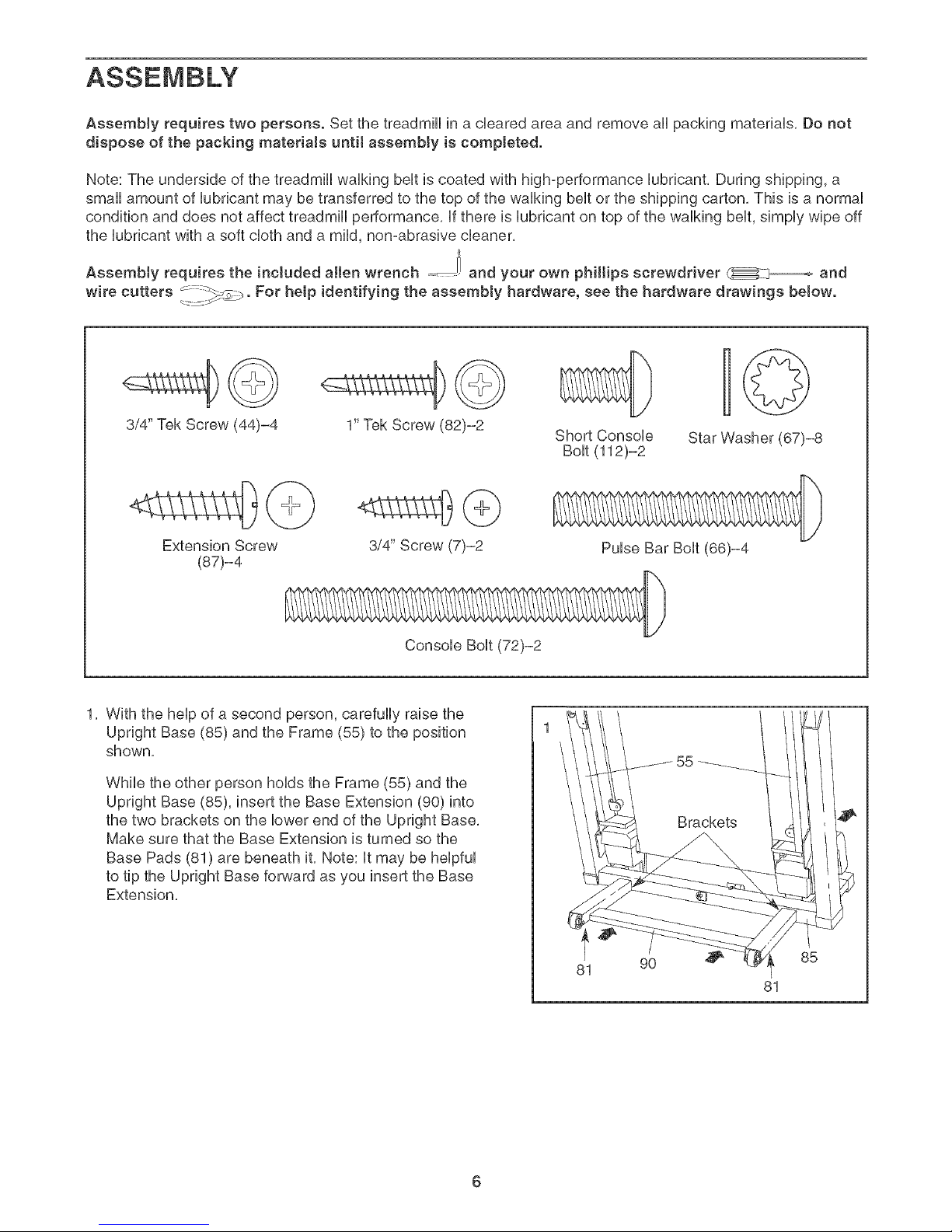
Assemblyrequirestwopersons.SetthetreadmHUinaclearedareaandremoveaHpackingmateriaUs.Donot
disposeofthepackingmaterialsuntilassemMyis completed.
Note:TheundersideofthetreadmHUwaUkingbeUtiscoatedwithhigh-performanceUubrbant.Duringshipping,a
smallamountofDbrbantmaybetransferredtothetopofthewaUkingbeUtortheshippingcarton.ThisisanormaU
conditionanddoesnotaffecttreadmHUperformance,ifthereisUubrbantontopofthewaUMngbeUt,simpUywipeoff
theUubricantwithasoftclothanda mild,non-abrasivecleaner.
Assemblyrequirestheincludedallenwrench_ andyourownphilHpsscrewdriver_ and
wire cutters _=_._. For help identifying the assembly hardware, see the hardware drawings below.
c'- _. ....
€@
3/4" Tek Screw (44)-4
1" Tek Screw (82)-2
<ssg }
Extension Screw
(87)-4
1. With the help of a second person, carefully raise the
Upright Base (85) and the Frame (55) to the position
shown,
While the other person holds the Frame (55) and the
Upright Base (85), insert the Base Extension (90) into
the two brackets on the lower end of the Upright Base.
Make sure that the Base Extension is turned so the
Base Pads (81) are beneath it. Note: it may be helpful
to tip the Upright Base forward as you insert the Base
Extension.
3/4" Screw (7)-2
Console Bolt (72)-2
Short Console Star Washer (67)-8
Pulse Bar Bolt (66)-4
I
81
6
90
85
81
Page 7
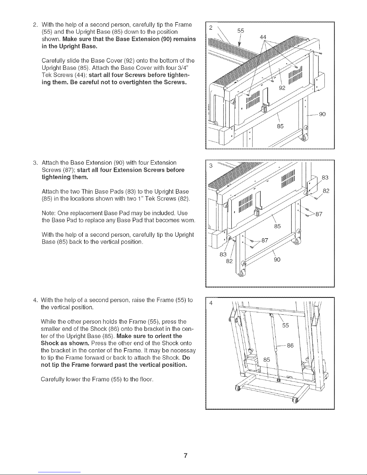
2,
With the heUpof a second person, carefully tip the Frame
(55) and the Upright Base (85) down to the position
shown, Make sure that the Base Extension (90} remains
in the Upright Base.
Carefully slide the Base Cover (92) onto the bottom of the
Upright Base (85), Attach the Base Cover with four 3/4"
Tek Screws (44); start all four Screws before tighten-
ing them, Be careful not to overtighten the Screws.
Attach the Base Extension (90) with four Extension
Screws (87); start all four Extension Screws before
tightening them.
Attach the two Thin Base Pads (83) to the Upright Base
(85) in the locations shown with two 1" Tek Screws (82),
55
44
Note: One replacement Base Pad may be included, Use
the Base Pad to replace any Base Pad that becomes worn,
With the help of a second person, carefully tip the Upright
Base (85) back to the vertical position,
4, With the heUpof a second person, raise the Frame (55) to
the vertbaU position,
While the other person hoUdsthe Frame (55), press the
smaller end of the Shock (86) onto the bracket in the cen-
ter of the Upright Base (85), Make sure to orient the
Shock as shown. Press the other end of the Shock onto
the bracket in the center of the Frame, it may be necessay
to tip the Frame forward or back to attach the Shock, Do
not tip the Frame forward past the vertical position.
Carefully lower the Frame (55) to the floor,
83
82
90
Page 8
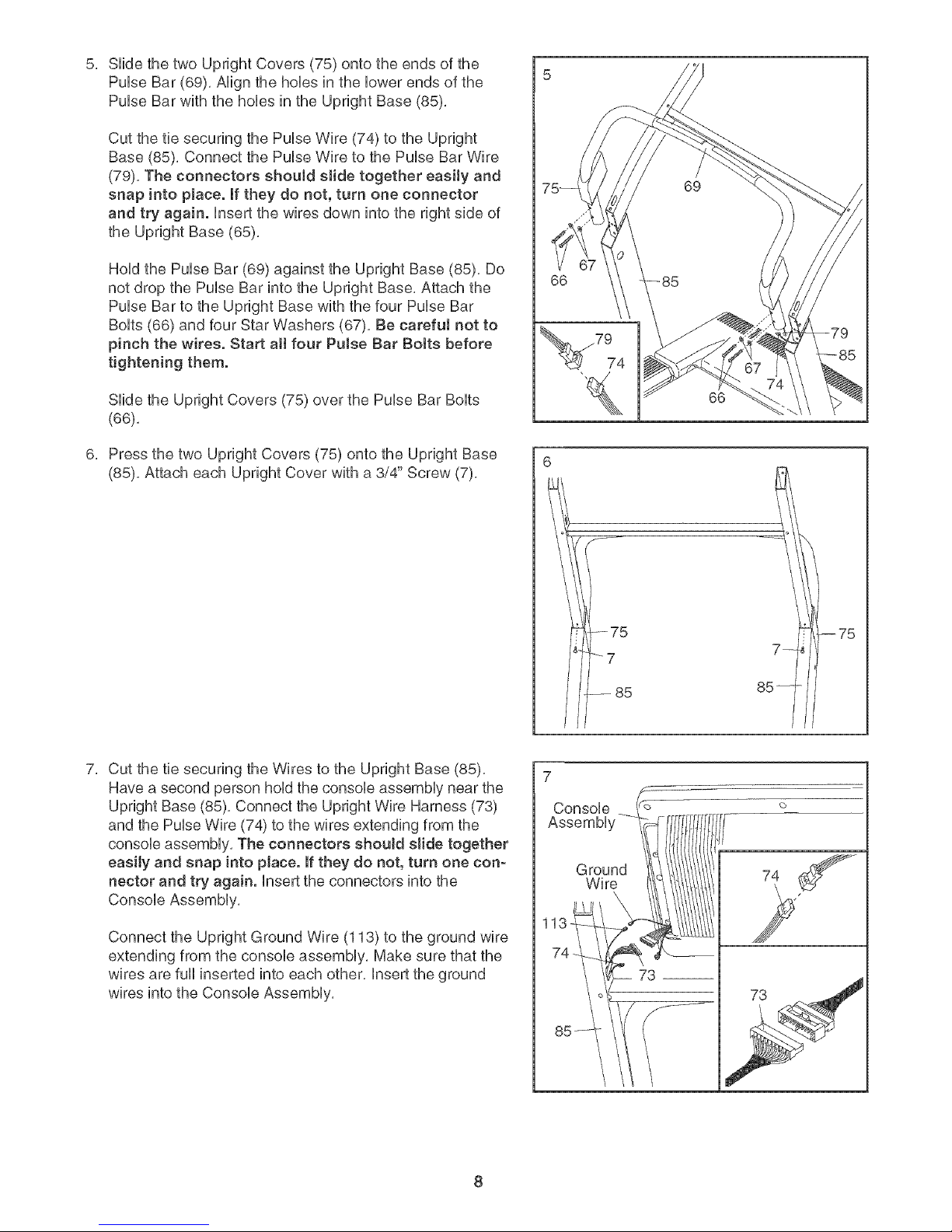
SHdethetwoUprightCovers(75)ontotheendsofthe
PuUseBar(69),AHgnthehoUesintheUowerendsofthe
PuUseBarwiththehoUesintheUprightBase(85),
CutthetiesecuringthePuUseWire(74)totheUpright
Base(85),ConnectthePuUseWiretothePuUseBarWire
(79),TheconnectorsshouJdslidetogethereasiJyand
snapinto place.Iftheydonot,turnoneconnector
andtryagain.Insertthewiresdownintotherightsideof
theUprightBase(65),
HoUdthePuUseBar(69)againsttheUprightBase(85),Do
notdropthePuUseBarintotheUprightBase,Attachthe
PuUseBartotheUprightBasewiththefourPuUseBar
BoUts(66)andfourStarWashers(67),Becarefulnotto
pinchthewires.Startallfour PulseBarBoltsbefore
tighteningthem.
SHdetheUprightCovers(75)overthePuUseBarBoUts
(66),
PressthetwoUprightCovers(75)ontotheUprightBase
(85),AttacheachUprightCoverwitha3/4"Screw(7),
66
79
74
--75
_7
.-- 85
66
--75
Cut the tie securing the Wires to the Upright Base (85),
Have a second person hold the console assembly near the
Upright Base (85), Connect the Upright Wire Harness (73)
and the Pulse Wire (74) to the wires extending from the
console assembly, The connectors shouJd shale together
easiJy and snap into pJace. If they do not, turn one con-
nector and try again. Insert the connectors into the
Console Assembly,
Connect the Upright Ground Wire (113) to the ground wire
extending from the console assembly, Make sure that the
wires are full inserted into each other, Insert the ground
wires into the Console Assembly,
7
Console
Assembl'
Ground
Wire
73
Page 9
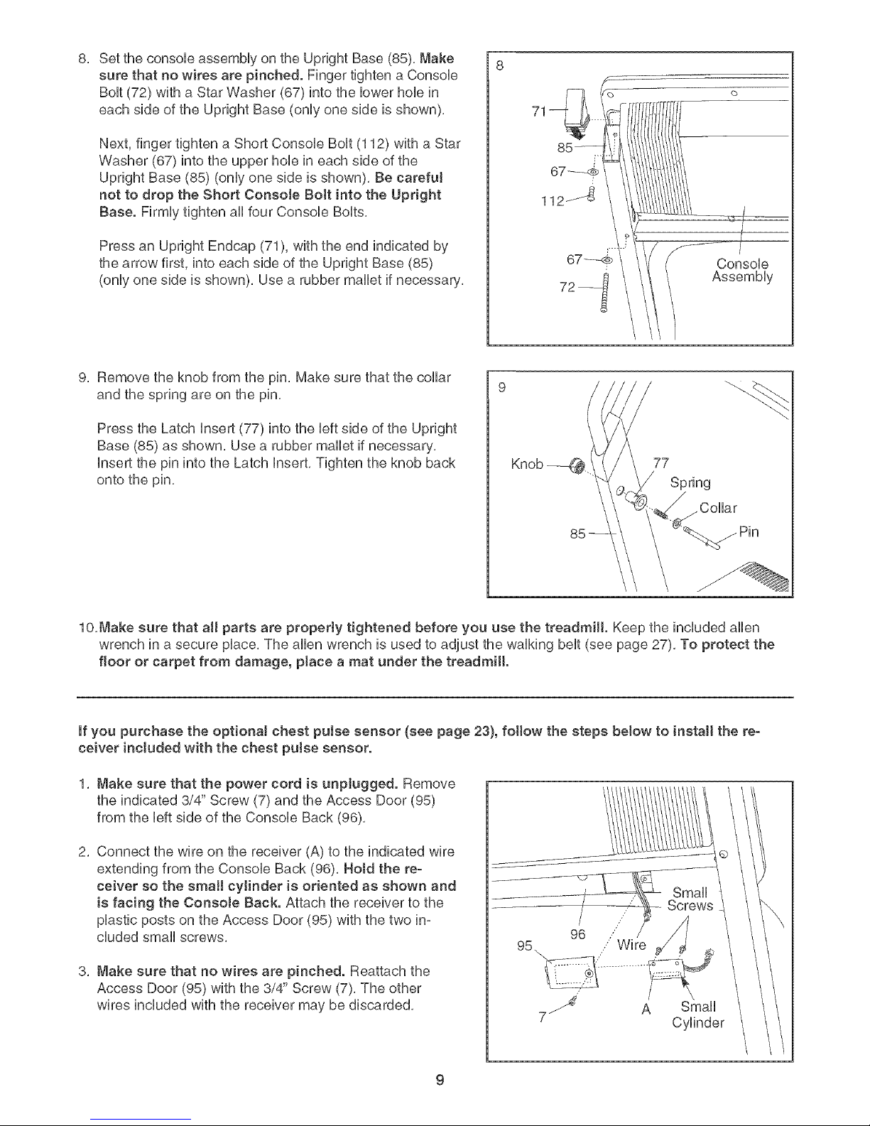
SettheconsobassemblyontheUprightBase(85).Make
surethatnowiresarepinched.FingertightenaConsob
Bolt(72)withaStarWasher(67)intothelowerhobin
eachsideoftheUprightBase(onlyonesideisshown).
Next,fingertightena ShortConsobBolt(112)witha Star
Washer(67)intotheupperhobineachsideofthe
UprightBase(85)(onlyonesideisshown).BecarefuJ
nottodroptheShortConsoJeBoltintotheUpright
Base.FirmlytightenallfourConsobBolts.
PressanUprightEndcap(71),withtheendindicatedby
thearrowfirst,intoeachsideoftheUprightBase(85)
(onlyonesideisshown),Usea rubbermalletif necessary,
9. Remove the knob from the pin. Make sure that the collar
and the spring are on the pin.
Press the Latch insert (77) into the left side of the Upright
Base (85) as shown. Use a rubber mallet if necessary.
insert the pin into the Latch insert. Tighten the knob back
onto the pin.
85---- I
112....
67-- i
72-
Console
Assembly
77
Spring
Collar
lO.Make sure that all parts are properly tightened before you use the treadmill. Keep the included allen
wrench in a secure place. The allen wrench is used to adjust the walking belt (see page 27). To protect the
floor or carpet from damage, place a mat under the treadmill.
if you purchase the optional chest puJse sensor (see page 23), follow the steps below to install the re-
ceiver included with the chest pulse sensor.
1. Make sure that the power cord is unplugged. Remove
the indicated 3/4" Screw (7) and the Access Door (95)
from the left side of the Console Back (96).
2, Connect the wire on the receiver (A) to the indicated wire
extending from the Console Back (96), Hold the re-
ceiver so the small cylinder is oriented as shown and
is facing the Console Back. Attach the receiver to the
plastic posts on the Access Door (95) with the two ino
cluded small screws.
3. Make sure that no wires are pinched. Reattach the
Access Door (95) with the 3/4" Screw (7). The other
wires included with the receiver may be discarded.
//
96 /
Wire
/
7 A
Small
Screws
Small
Cylinder
Page 10
OPERATION AND ADJUSTMENT
THE PRE-LUBRmCATED WALKmNG BELT
Your treadmHUfeatures a waUking beUtcoated with high°
performance Uubrbant, IMPORTANT: Never apply sil-
icone spray or other substances to the walking
belt or the walking platform. Such substances will
deteriorate the walking belt and cause excessive
wear.
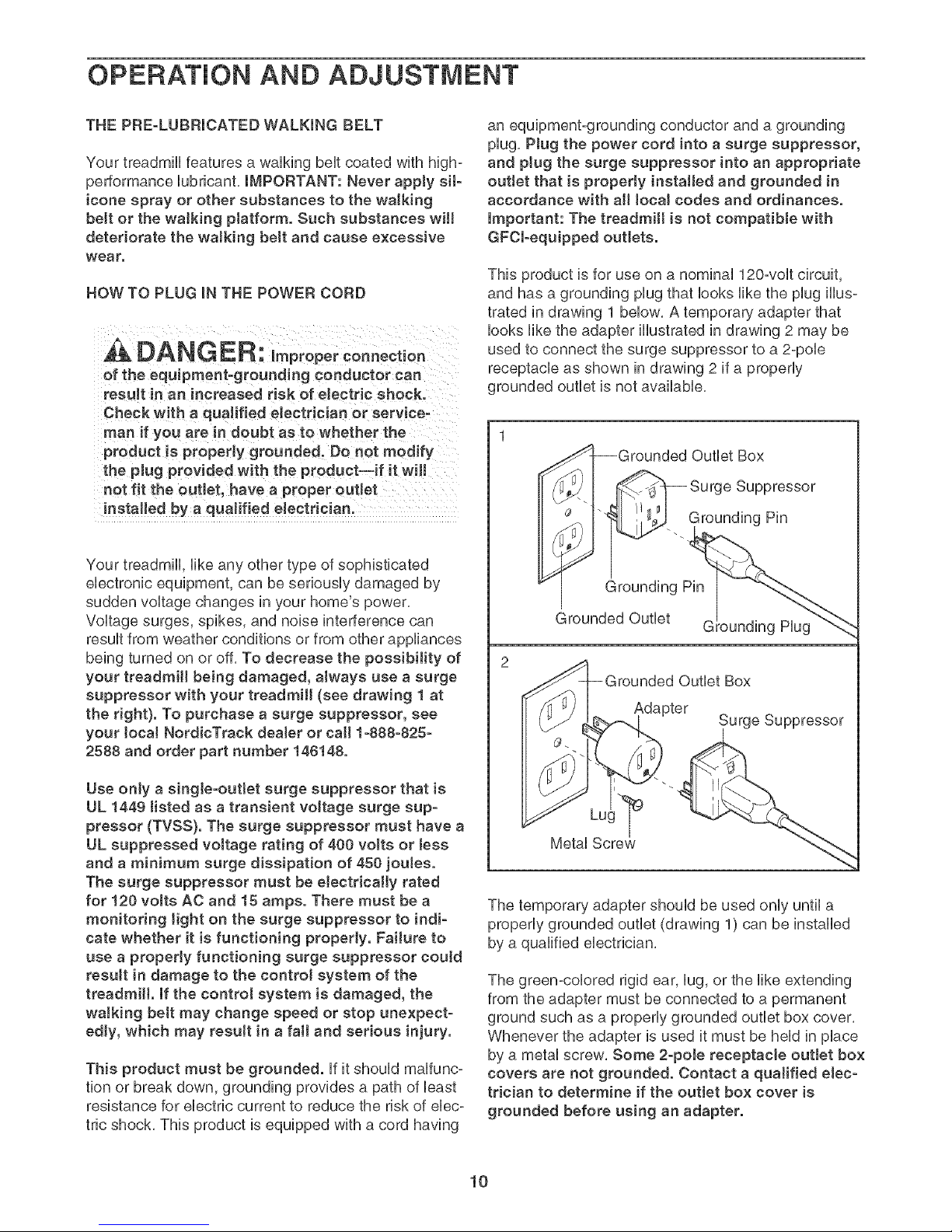
HOW TO PLUG mNTHE POWER CORD
of the equipment-grounding conductor can
result in an increased risk of electric shock.
Check with a qualified electrician or service-
man if you are In doubt as to whether the
product is properly grounded, Do not modify
the plug provided with the product--if it will
not fit the outlet, have a proper ouUet
installed by a qualified electrician.
Your treadmill, like any other type of sophisticated
electronic equipment, can be seriously damaged by
sudden voltage changes in your home's power,
Voltage surges, spikes, and noise interference can
result from weather conditions or from other appliances
being turned on or off, To decrease the possibility of
your treadmill being damaged, always use a surge
suppressor with your treadmill (see drawing 1 at
the right}. To purchase a surge suppressor, see
your Joca! NordicTrack deaJer or call 1-888-825-
2588 and order part number 148148.
an equipment-grounding conductor and a grounding
plug, PJug the power cord into a surge suppressor,
and plug the surge suppressor into an appropriate
outlet that is properly installed and grounded in
accordance with aH local codes and ordinances.
Important: The treadmill is not compatible with
GFCl-equipped outJets.
This product is for use on a nominal 120-volt circuit,
and has a grounding plug that looks like the plug illus-
trated in drawing 1 below, A temporary adapter that
looks like the adapter illustrated in drawing 2 may be
used to connect the surge suppressor to a 2-pole
receptacle as shown in drawing 2 if a properly
grounded outlet is not available,
-Grounded Outlet Box
_._ -- _urge Suppressor
i
_< --. Grounding Pin
Grounding Pin
_rounded Outlet G g Hug
2
_rounded Outlet Box
Adapter
Surge Suppressor
Use onJy a singJe-ouflet surge suppressor that is
UL 1449 tisted as a transient voltage surge sup-
pressor (TVSS). The surge suppressor must have a
UL suppressed voltage rating of 400 volts or Jess
and a minimum surge dissipation of 450 joutes.
The surge suppressor must be electrically rated
for 120 volts AC and 15 amps. There must be a
monitoring Jight on the surge suppressor to indi-
cate whether it is functioning properly. Failure to
use a properJy functioning surge suppressor could
resuJt in damage to the contro! system of the
treadmill. If the control system is damaged, the
waJking belt may change speed or stop unexpect-
edly, which may result in a fall and serious injury.
This product must be grounded, ff it should maffunc°
tion or break down, grounding provides a path of least
resistance for electric current to reduce the risk of ebc°
tric shock, This product is equipped with a cord having
The temporary adapter should be used only until a
properly grounded outlet (drawing 1) can be installed
by a qualified electrician,
The green°colored rigid ear, lug, or the like extending
from the adapter must be connected to a permanent
ground such as a properly grounded outlet box cover,
Whenever the adapter is used it must be held in place
by a metal screw, Some 2-poJe receptacle outlet box
covers are not grounded. Contact a qualified elec-
trician to determine if the outlet box cover is
grounded before using an adapter.
10
Page 11
CONSOLE DmAGRAM
Time
-----"-;:5j_
Heart Rate
t t--trt
I l_tLt ,,
Speed
_-t.Zi
Auf,,Breez_,
Fat] C)(:JOrTl{ !h-!r
3
A lnc/ine
t,, 12 % g, _,],
V
Note: if there is a thin sheet of plastic
on the face of the console, remove it,
Odo_Ir_eter
tC
S I 6
I Step_peed
mph
N
Start
Stop
Progro t_)s
rralnitTg Zones
PerW_rma_e
Ez_d_ran_e
Aerol_;_ _
r_t B_m _
I lea rt
/,_ate
/', .....................
7 8 9 10
@peed
A
V
FEATURES OF THE CONSOLE
The treadmill console offers an impressive array of
features designed to help you get the most from your
workouts, When the manual mode of the console is se-
lected, the speed and incline of the treadmill can be
changed with the touch of a button, As you exercise,
the console will display continuous exercise feedback,
You can even measure your heart rate using the built-
in handgrip pulse sensor or the optional chest pulse
sensor (see page 23),
in addition, the console features eight preset programs,
Each program automatically controls the speed and in-
cline of the treadmill as it guides you through an effeco
tive workout, The console also offers two heart rate pro°
grams that control the speed and incline of the treadmill
to keep your heart rate near a target heart rate during
your workouts, Note: You must wear the optional chest
pulse sensor to use the heart rate programs,
The console also features iFiT,com interactive technol-
ogy, Having iFIT,com technology is like having a per-
sonal trainer in your home, Using a stereo audio cable,
you can connect the treadmill to your portable stereo,
home stereo, computer, or VCR and play special
iFiT,com MP3, CD, and video programs (iFiT,com MP3
programs, CDs, and videocassettes are available sepa-
rately), iFiT,com programs automatically control the
speed and incline of the treadmill as a personal trainer
guides you through every step of your workout; high-
energy music provides added motivation, To down-
load iFiT.com MP3 programs, go to wwwJFlT.com.
To purchase iFiT.com CDs or videocassettes, ca[[
toil-free 1-888-825-2588.
With the treadmill connected to your computer, you
can also go to wwwJFIT,com and access iFIT,com
programs directly from our Web site, See
www.iFlT.com for more information.
To use the manua! mode of the conso[e, follow the
steps beginning on page 12, To use a preset
program, see page 15, To use a heart rate program,
see page 16, To use an iFIT.com MP3, CD, or video
program, see page 20, To use an iFlT.com program
direct[y from our Web site, see page 22,
11
Page 12

HOW TO TURN ON THE POWER
Hug in the power cord (see page 10),
Locate the reset/off
circuit breaker near
the power cord, Make
sure that the circuit
On
Position
breaker is in the reset
position,
Stand on the foot rails of the treadmill. Find the clip
attached to the key (see the drawing on page 11)
and attach the clip onto the waistband of your
clothes. Next, insert the key into the console. After
a moment, the display wiii light, Test the clip by
carefully taking a few steps backward until the
key is pulled from the console. If the key is not
pulled from the console, adjust the position of
the clip as needed.
if the Start button or the
Speed increase button m m
Speed
is pressed, the walking _}o_
belt will begin to move at
1 mph. As you exercise,
change the speed of the
walking belt as desired by pressing the Speed in-
crease and decrease buttons. Each time a button
is pressed, the speed setting wiii change by 0.1
mph; if a button is held down, the speed setting
wiii change in increments of 0.5 mph. Note: After
the buttons are pressed, it may take a moment for
the walking belt to reach the selected speed setting.
if one of the 1-Step Speed buttons is pressed, the
walking belt will gradually increase in speed until it
reaches the selected speed setting,
To stop the walking belt, press the Stop button,
The time will begin to flash in the display, To
restart the walking belt, press the Start button, the
Speed increase button, or one of the 1°Step Speed
buttons,
Insert the key into the console,
See HOW TO TURN ON THE POWER above,
Select the manual mode.
When the
key is in-
serted, the
manual
mode wiii
mmmlBmtm
I I
! u
w M
i i
mimMUE_E
Odometer Track
m
be selected.
if a program
has been selected, reselect the manual mode by
pressing the Programs button repeatedly until a
track appears in the center of the display. Make
sure that the word "Programs" does not appear
below the track.
Start the walking belt.
To start the walking belt, press the Start button,
the Speed increase button, or one of the ten
loStep Speed buttons,
Note: The first time the treadmill is used, observe
the alignment of the walking belt, and align the
walking belt if necessary (see page 27).
Change the incline of the treadmill as desired.
To change the incline of
the treadmill, press the .....,,,,o
Incline increase and de- _l _"t
crease buttons, Each _ioLl
time a button is pressed,
the incline will change by
0,5%, Note: After the buttons are pressed, it may
take a moment for the treadmill to reach the se-
lected incline setting,
Follow your progress with the disptay.
When the
manual
mode or the
iFIT.com
mode is se-
m u
m B
l 8
BB_B
Odometer Track
m
l
center of the
display wiii show a 1/4-mile track. As you walk or
run, the indicators around the track wiii light in suc-
cession until the entire track is lit. The track wiii
then darken and the indicators will again begin to
light in succession.
12
Page 13

The lower right area of
the display wiii show a
training zone bar that in-
intensity level of your ex-
ercise, if five or six indi-
cators in the bar are lit,
Training 7ones
Performa_ce
Aeroblc
_t B_rn
W_rm Up
Coo! Down
for exam#e, the bar
shows that your pace is
ideal for aerobic exercise,
The upper left area of
the display wiii show the
incline level of the tread°
mill, the elapsed time,
and the approximate
carbs you have burned, Note: Each time the in-
cline changes, the display will show the incline
setting for a few seconds, When a program is se-
lected, the display wiii show the time remaining in
the program instead of the elapsed time,
Calories
display wiii show the I _! Y"l
i Zdut
calories you have
burned, The display wiii
also show your heart
rate when you use the handgrip pulse sensor or
the optional chest pulse sensor,
The upper right area of
the display wiii show
the speed of the walk-
ing belt and your pace
(pace is measured in
minutes per mile),
Note: The console can
display speed and dis- ,_
tance in either miles or _
kilometers, To determine
which unit of measure°
ment is selected, hold
down the Stop button while inserting the key into
the console, An "E" for English miles or an "M" for
metric kilometers will appear in the upper right
area of the display, Press the Speed increase but-
ton to change the unit of measurement, When the
desired unit of measurement is selected, remove
the key, Note: For simpJicity, aH instructions in
this section refer to miles.
Speed
The lower center of the
Od_meter
display wiii show the dis°
tance that you have
',.5
walked or run during your
workout,
To see the total number of miles that the walking
belt has moved since the treadmill was purchased,
press the Odometer button; the words "Total Miles"
and the total number of miles wiii appear in the dis-
play,
To see the number of miles that the walking belt
has moved during the last week, the last month, or
another period of time, press the Odometer button
again; the words "My Total" and the total number
of miles will appear in the display, To reset this
number, hold down the Odometer button for a few
seconds,
To see the distance that you have walked or run
during your workout, press the Odometer button
again,
To reset the display, press the Stop button, re-
move the key, and then reinsert the key.
Measure your heart rate if desired.
Note: if you
use the
handgrip
pulse sensor
and the op-
tional chest
pulse sensor
at the same
time, the Contacts
console will
not display
your heart rate accurately, Before using the hand°
grip pulse sensor, remove the clear plastic film
from the metal contacts, in addition, make sure
that your hands are clean, To measure your heart
rate, stand on the foot rails and hold the metal
contacts--avoid moving your hands. When your
pulse is detected, the heart symbol in the upper
center of the display will appear, one or two
dashes will appear, and then your heart rate will
be shown. For the most accurate heart rate
reading, continue to hold the contacts for about
15 seconds.
13
Page 14

Turn on the fan if desired.
To turn on the fan at low
speed, press the ,_,, odo,,,e_,
AutoBreeze Fans button;
the word "Fan" and the
number 1 wHUappear in
the dispUay, To turn on
the fan at medium speed, press the button a sec-
ond time; the number 2 wHUappear in the dispUay,
To turn on the fan at high speed, press the button
a third time; the number 3 wHUappear in the dis-
pUay,To seUectthe auto mode, press the button
again; the word "Auto" wHUappear in the dispUay,
When the auto mode is seUected, the speed of the
fan wHUautomatically increase and decrease as
the speed of the waUkingbeUtincreases and de-
creases,
To turn off the fan, press the AutoBreeze Fan but-
ton again, Note: A few minutes after the walking
belt is stopped, the fan will automatically turn off,
When you are finished exercising, remove the
key.
Step onto the foot rails, press the Stop button, and
adjust the incline of the treadmill to the Jowest
setting, The incline must be at the lowest setting
when the treadmill is fotded to the storage posi-
tion or the treadmill will be damaged, Next, re-
move the key from the console and put it in a se-
cure place, Note: if the display remains lit after
the key is removed, the console is in the
"demo" mode, See page 23 and turn off the
demo mode,
When you are finished using the treadmill, switch
the reset/off circuit breaker to the off position and
unplug the power cord,
14
Page 15

HOW T@ USE A PRESET PROGRAM
mnsertthe key into the console.
See HOW TO TURN ON THE POWER on page
12,
Select one of the preset programs.
To sebct
one of the
eight preset
programs,
press the
Programs
UMMmm_W_
mlmlmBm_!
EMmmmum_mu
Ortom¢_ter Programs
_It't¢'t
LIoLI LI ........... ,_
I u
M m m I_g m E _
button re-
peatedUy
until the
words "Weight Loss," "Aerobic," or "Performance"
and the number 1,2, or 3 appear in the bwer cen-
ter of the dispUay,
matrix,) The speed settings for the next seven
segments will be shown in the seven columns to
the right,
When only three seconds remain in the first seg-
ment of the program, both the Current Segment
column and the column to the right will flash and a
series of tones will sound, if the speed and/or in-
cline of the treadmill is about to change, the speed
setting and/or the incline setting wiii flash in the
display to alert you,
When the first segment is completed, all speed
settings will move one co/umn to the left, The
speed setting for the second segment will then be
shown in the flashing Current Segment column
and the treadmill will automatically adjust to the
speed and incline settings for the second seg-
ment, Note: If all seven of the indicators in the
Current Segment column are lit, the speed settings
may move downwardso that only the highest indi-
cators appear in the matrix,
As each preset program is sebcted, the maximum
speed setting of the program and the maximum
incline setting of the program wHUflash in the dis-
pUayfor a few seconds, The dispUaywill then show
how long the program will last, A profile of the
speed settings of the program will scroll across
the matrix in the center of the display,
Press the Start button or the Speed increase
button to start the program.
A moment after the button is pressed, the tread-
mill will automatically adjust to the first speed and
incline settings for the program, Hold the handrails
and begin walking,
Each program is divided into 20, 30, or 40 one-
minute segments, One speed setting and one in-
cline setting are programmed for each segment,
Note: The same speed setting and/or incline setting
may be programmed for two or more consecutive
segments,
The speed
setting for
the first seg- ,,_uim, sl_,
ment will be
shown in the Current Segment
flashing
Current
Segment column of the matrix in the center of the
display, (The incline settings are not shown in the
The program will continue in this way until the
speed setting for the last segment is shown in the
Current Segment column and the last segment
ends, The walking belt wiii then slow to a stop,
if the speed or incline setting for the current
segment is too high or too low, you can manually
override the setting by pressing the Speed or
Incline buttons, Every few times a Speed button is
pressed, an additional indicator wiii light or darken
in the Current Segment column; if any of the
columns to the right of the Current Segment cop
umn have the same number of lit indicators as the
Current Segment column, an additional indicator
may light or darken in those columns as well,
important: When the current segment of the
program ends, the treadmill will automatically
adjust to the speed and incline settings for the
next segment.
To stop the program at any time, press the Stop
button, The time wiii begin to flash in the display,
To restart the program, press the Start button or
the Speed increase button, The walking belt will
begin to move at 1 mph, When the next segment
of the program begins, the treadmill wiii automati-
cally adjust to the speed and incline settings for the
next segment,
15
Page 16

Fottow your progress with the display. HOW TO USE A HEART RATE PROGRAM
See step 5 on page 12,
Measure your heart rate if desired.
See step 6 on page 13,
Turn on the fan if desired.
See step 7 on page 14,
When you are finished exercising, remove the
key from the console.
When the program has ended, make sure that
the incline of the treadmill is at the lowest set-
ting. Next, remove the key from the consob and
put it in a safe pUace,Note: If the display remains
tit after the key is removed, the console is in
the "demo" mode. See page 23 and turn off the
demo mode.
When you are finished using the treadmill switch
the reset/off circuit breaker to the off position and
unpUugthe power cord,
A t,CAUTION:. youhaveheartprob-
lems, or if you are over 60 years of age and
have been inactive, do not use the heart rate
programs, ff you are taking medication regu-
larly, consult your physician to find whether the
medication will affect your exercise heart rate.
Follow the steps below to use a heart rate program,
Put on the optional chest pulse sensor.
You must wear the optionN chest puJse sensor
(see page 23) to use a heart rate program.
Insert the key into the consote.
See HOW TO TURN ON THE POWER on
page 12,
Select a heart rate program.
To select a
heart rate m
program,
press the Od_m_4er Programs
Programs ¢_ _t _
button re-
peatedly until ............
the words
"Heart Rats"
and the number 1 or 2 appear in the lower center
of the display,
LtoLl LI
When a heart rate program is selected, the matrix
in the center of the display wiii show a moving
graphic that represents your heart rate, Each time
a heartbeat is detected, an additional peak will ap-
pear,
16
Page 17

Enter a maximum heart rate setting.
When a heart rate pro-
gram is sebcted, the ..........
words "Heart Rate" wHU t ""l £"_
appear in the upper cen-
I 1 Lt
ter of the dispUayand the
target heart rate setting
for the program wHUflash, ff desired, press the
Heart Rate increase and decrease buttons to ad-
just the target heart rate setting, Note: See the
heart rate chart on page 28 for heart rate guide-
lines.
Press the Start button or the Speed increase
button to start the program.
A moment after the button is pressed, the tread-
mill will automatically adjust to the first speed and
incline settings of the program, Hold the handrails
and begin walking,
Each heart rate program is divided into 20 one-
minute segments. One target heart rate is pro-
grammed for each segment. Note: The same tar-
get heart rate setting may be programmed for two
or more consecutive segments.
The program wiii continue in this way until the last
segment ends. The walking belt will then slow to a
stop,
if the speed or incline setting is too high or too low
at any time during the program, you can adjust the
setting with the Speed or Incline buttons. However,
each time the console compares your heart rate to
the target heart rate, the speed and/or incline of
the treadmill may automatically change to bring
your heart rate closer to the target heart rate.
if your pulse is not detected during the program,
the letters "PLS" wiii flash in the display and the
speed and incline of the treadmill may automati-
cally decrease, if this occurs, see the instructions
included with the optional chest pulse sensor.
To stop the program at any time, press the Stop
button, The time wiii begin to flash in the display,
To restart the program, press the Start button or
the Speed increase button, The walking belt will
begin to move at 1 mph, When the console com-
pares your heart rate to the target heart rate, the
speed and/or incline of the treadmill may automat-
ically change to bring your heart rate closer to the
target heart rate,
During each segment, the console will regularly
compare your heart rate to the current target heart
rate. if your heart rate is too far below or above
the target heart rate, the speed and/or incline of
the treadmill will automatically increase or de-
crease to bring your heart rate closer to the target
heart rate.
During the last three seconds of each segment, a
series of tones will sound and the speed setting
and the incline setting will flash in the display.
Follow your progress with the display.
See step 5 on page 12,
Turn on the fan if desired.
See step 7 on page 14,
When you are finished exercising, remove the
key from the console.
See step 7 on page 16,
17
Page 18

HOW TO CONNECT THE TREADMmLL TO USE
mFIT.COM PROGRAMS
To use iFlT.com MP3 or CD programs, the treadmHH
must be connected to your MP3 pHayer,CD pHayer,
portabHestereo, home stereo, or computer, See pages
18 and 19 for connecting instructions, To use iFlT.com
programs directly from our Web site, the treadmHH
must be connected to your computer, See page 19 for
connecting instructions, To use iFlT.com video pro-
grams, the treadmHHmust be connected to your VCR.
See page 20 for connecting instructions,
HOW TO CONNECT YOUR PORTABLE STEREO
Note: mfyour stereo has an RCA-type AUDIO OUT
jack, see instruction A below, mfyour stereo has a
1/8" LINE OUT jack, see instruction B. If your
stereo has only a PHONES jack, see instruction C.
A. Hug one end of a Hong1/8" to RCA stereo audio
came (avaiHabHeat eHectronics stores) into the input
jack on the consoHe. Hug the other end of the came
into the AUDHOOUT jack on your stereo.
A/B
HOW TO CONNECT YOUR MP3 PLAYER OR CD
PLAYER
A. Hug one end of the incHuded 1/8" to 1/8" stereo
audio came into the input jack on the consoHe. Hug
the other end of the came into a jack on your MP3
pHayeror CD pHayer. Hug your headphones into the
headphone jack on the consoHe.
CaMe
....Headphones
,'@© @_ _
Audio CaMe
B,
See the drawing above, Hug one end of a Hong1/8"
to 1/8" stereo audio came (avaiHabHeat eHectronics
stores) into the input jack on the consoHe. Hug the
other end of the came into the LHNEOUT jack on
you r stereo,
C,
Hug one end of a Hong1/8" to 1/8" stereo audio
came (avaiHabHeat eHectronics stores) into the input
jack on the consoHe. Hug the other end of the came
into the PHONES jack on your stereo, Hug your
headphones into the headphone jack on the consoHe.
18
r
u ©
,@ @,
L-_---I--
.... Headphones
PNONES@)::
Audio
CaMe
Page 19

HOW TO CONNECT YOUR HOME STEREO HOW TO CONNECT YOUR COMPUTER
Note: If your stereo has an unused LINE OUT jack,
see instruction A below. If the LINE OUT ack is
being used, see instruction B.
A, Hug one end of a long 1/8" to RCA stereo audio
cabb (availabb at ebctronbs stores) into the input
jack on the consob, Hug the other end of the cabb
into the LiNE OUT jack on your stereo,
A
r
LI,EOUT®i
.............. 1....
B, Hug one end of a long 1/8" to RCA stereo audio
cable (available at electronics stores) into the input
jack on the console, Plug the other end of the cable
into an RCA Y-adapter (available at electronics
stores), Next, remove the wire that is currently
plugged into the LiNE OUT jack on your stereo and
plug the wire into the unused side of the Y-adapter,
Hug the Y-adapter into the LiNE OUT jack on your
stereo,
A, Hug one end of a long 1/8" to 1/8" stereo audio
cable (available at electronics stores) into the input
jack on the console, Hug the other end of the cable
into the LiNE OUT jack on your computer, Hug your
headphones into the headphone jack on the console,
A
.@@. -..............
.. ..... i ? i
.... Headphones
........ ......
Audio Cable
i
=1
=1 ooc
,@-@,
]CD ]
Audio Y-adapter
Cabb
Wire removed from__
LiNE OUT jack
RCA
19
Page 20

HOW TO CONNECT YOUR VCR
Note: if your VCR has an unused AUDIO OUT jack,
see instruction A below, if the AUDIO OUT jack is
being used, see instruction B. ff you have a TV
with a built-in VCR, see instruction B. ff your VCR
is connected to your home stereo, see NOW TO
CONNECT YOUR HOME STEREO on page 19.
A, Hug one end of a long 1/8" to RCA stereo audio
cable (available at electronics stores) into the input
jack on the console, Hug the other end of the cable
into the AUDIO OUT jack on your VCR,
A
r u
L£t2J
Audio Cable
B. Hug one end of a long 1/8" to RCA stereo audio
cable (available at electronics stores) into the input
jack on the console. Hug the other end of the cable
into an RCA Y-adapter (available at electronics
stores). Next, remove the wire that is currently
plugged into the AUDIO OUT jack on your VCR and
plug the wire into the unused side of the Y-adapter.
Hug the Y-adapter into the AUDIO OUT jack on
your VCR.
HOW TO USE AN mFIT.COM MP3, CD, OR VmDEO
PROGRAM
To use an iFIT.com MP3, CD, or video program, the
treadmill must be connected to your MP3 player, CD
player, or VCR. See HOW TO CONNECT THE
TREADMILL TO USE IFIT.COM PROGRAMS on
pages 18 to 20, To download iFIT.com MP3 pro-
grams, go to wwwJFIT.com. To purchase iFIT.com
CDs or videocassettes, call toil-free 1-888-825-2588.
Follow the steps below to use an iFIT.com MP3, CD,
or video program.
insert the key into the console.
See HOWTO TURN ON THE POWER on page 12,
Select the iFIT.com mode.
To select the
iFIT,com
mode, press
the
Programs
button until
the letters
Odocnet_r Prograr_
FIFI_
LLLI Ll i _T
"iFIT" ap-
pear in the
display,
Press the PJay button on your MP3 player, CD
player, or VCR.
Note: if you are using an iFIT.com CD, insert the
CD into your CD player; if you are using an
iFIT.com videocassette, insert the videocassette
into your VCR.
AUDIO OUT jack
A moment after the Hay button is pressed, your
personal trainer wiii begin guiding you through
your workout. Simply follow your personal trainer's
instructions. Note: if the time is flashing in the dis°
play, press the Start button or the Speed increase
button on the console. The treadmill will not re-
spond to an MP3, CD, or video program while the
time is flashing in the display.
During the program, an electronic "chirping" sound
will alert you when the speed and/or incline of the
treadmill is about to change. CAUTION: Always
tisten for the "chirp" and be prepared for speed
and/or incJine changes. In some instances, the
speed and/or incline may change before your
personal trainer describes the change.
2O
Page 21

if the speed or incline settings are too high or too
low, you can manually override the settings at any
time by pressing the Speed or Incline buttons on
the console, However, when the next "chirp" is
heard, the speed and/or incline wilt change to
the next settings of the program.
• Make sure that the audio cable is properly
connected.
• If you are using a portable CD pJayer and the
CD skips, set the CD player on the floor or an-
other flat surface instead of on the consote.
To stop the walking belt at any time, press the
Stop button on the console, The time wiii begin to
flash in the display, To restart the program, press
the Start button or the Speed increase button,
After a moment, the walking belt wiii begin to
move at 1 mph, When the next "chirp" is heard,
the speed and/or incline will change to the
next settings of the program,
When the program is completed, the walking belt
will stop, Note: To use another MP3, CD, or video
program, press the Stop button or remove the key
and go to step 1 on page 20,
Note: If the speed and/or incline of the treadmill
does not change when a "chirp" is heard:
• Make sure that the letters '1FIT" appear in the
display and that the time is not flashing in the
display. If the time is flashing, press the Start
button or the Speed increase button on the
console.
• Adjust the volume of your MP3 player, CD
player, or VCR. If the volume is too high or too
tow, the console may not detect the program
signals.
See the "The incline of the treadmill does not
change correctly" on page 27.
Fottow your progress with the display.
See step 5 on page 12,
Measure your heart rate if desired.
See step 6 on page 13,
Turn on the fan if desired,
See step 7 on page 14,
When you are finished exercising, remove the
key from the console,
See step 7 on page 16,
CAUTION: AJways remove iFIT.com CDs and
videocassettes from your CD player and VCR
and disconnect your MP3 player when you are
not using them.
21
Page 22

HOW TOUSE AN IFIT:COM PROGRAM
DIRECTLY FROM OUR WEB SiTE
Return to the treadmill and stand on the foot
rails. Find the clip attached to the key and sJide
the clip onto the waistband of your clothes.
Our Web site at wwwJFiT,com allows you to access
basic programs, audio programs, and video programs
directly from the internet, Additionai options are soon to
be avaHabie, See wwwJFiT,com for details,
To use programs from our Web site, the treadmHi must
be connected to your home computer, See HOW TO
CONNECT YOUR COMPUTER on page 19, in
addition, you must have an internet connection and
an internet service provider, A Hstof specific system re-
quirements is found on our Web site,
Follow the steps bellow to use a program from our
Web site,
insert the key into the consote.
See HOW TO TURN ON THE POWER on page 12,
Select the iFIT.com mode.
To select the
iFiT,com
mode, press
the
Programs
button until
the ietters
OdoK_etet" Pro[_ram_
LLLI LI iH_
"iFHT"ap-
pear in the
dispiay,
Go to your computer and start an intemet
connection.
When the on-screen countdown ends, the program
wiii begin and the walking belt wiii begin to move,
Hold the handraiHs,step onto the walking belt, and
begin walking, During the program, an electronic
"chirping" sound will alert you when the speed
and/or incline of the treadmill is about to change,
CAUTION: AJways listen for the "chirp" and be
prepared for speed and/or incline changes.
if the speed or incline settings are too high or too
low, you can manually override the settings at any
time by pressing the Speed or Incline buttons on
the console, However, when the next "chirp" is
heard, the speed and/or incJine wilt change to
the next settings for the program.
To stop the walking belt at any time, press the
Stop button on the console, The time wiii begin to
flash in the display, To restart the program, press
the Start button or the Speed increase button,
After a moment, the walking belt will begin to
move at 1,0 mph, When the next "chirp" is
heard, the speed and incline wilt change to the
next settings of the program,
When the program is completed, the walking belt
will stop, Note: To use another program, press the
Stop button and go to step 5,
Note: If the speed and/or incJine of the treadmill
does not change when a "chirp" is heard, make
sure that the tetters "iFIT" appear in the display
and that the time is not flashing in the display.
In addition, make sure that the audio cable is
properly connected.
Start your web browser, if necessary, and go to
our Web site at www.iFIT.com.
Follow the desired tinks on our Web site to se-
tecta program.
Read and follow the onqine instructions for using a
program,
Follow the on-tine instructions to start the
program.
When you start the program, an on-screen count-
down will begin,
Fottow your progress with the disptay.
See step 5 on page 12,
When you are finished exercising, remove the
key from the consote.
See step 7 on page 16,
22
Page 23

THE INFORMATION MODE/DEMO MODE THE OPTmONAL CHEST PULSE SENSOR
The consoUefeatures an information mode that keeps
track of the totaUnumber of hours that the treadmHUhas
been operated and the totaUnumber of miles that the
waUkingbeUthas moved, The information mode aUsoaU-
Uowsyou to seUect miles or kilometers as the unit of
measurement and to turn on and turn off the demo
mode,
To seUectthe information mode, hoUddown the Stop
button while inserting the key into the consoUe,When
the information mode is seUected,the following informa-
tion wHUbe shown in the dispUay:
area of the dis-
pUaywill show the
total number of
hours that the
treadmill has
been used, The
lower center of
the display will
show the total number of miles (or kilometers) that the
walking belt has moved, An "E" for English miles or an
"M" for metric kilometers will appear in the upper right
area of the display, Press the Speed increase button to
change the unit of measurement,
m R
bEm ;-
I
Hours
aC.t,_l _-
ILI Miles
An optional chest pulse sensor adds even more fea-
tures to the console, The chest pulse sensor offers
hands-free operation, and enables you to use the con-
sole's two heart rate programs, To purchase the op-
tional chest putse sensor, call toil-free 1-888-825-
2588.
IMPORTANT: If a "d" appears in the upper center of
the display, the console is in the "demo" mode, This
mode is intended to be used only when a treadmill is
displayed in a store, When the console is in the demo
mode, the power cord can be plugged in, the key can
be removed from the console, and the indicators in the
display will automatically light in a preset sequence, al-
though the buttons on the console will not operate, If a
"d" appears when the information mode is selected,
press the Speed decrease button so "d" disap-
pears.
To exit the information mode, remove the key from the
console,
23
Page 24

HOW TO FOLD AND MOVE THE TREADMILL
HOW TO FOLD THE TREADMmLL FOR STORAGE
Before folding the treadmill, adjust the incline to the
towest position, ff this is not done, the treadmill may be per-
manently damaged. Remove the key and unptug the power
cord. CAUTmON: You must be able to safely tift 45 pounds
(20 kg) to raise, lower, or move the treadmill.
1, HoUdthe treadmHUwith your hands in the Uocation shown by
the arrow at the right, CAUTION: To decrease the possi-
biJity of injury, bend your tegs and keep your back
straight. As you raise the treadmill, make sure to lift
with your tegs rather than your back. Raise the treadmill
about halfway to the vertical position,
2, Move your right hand to the position shown and hold the
treadmill firmly, Using your left hand, pull the latch knob to
the left and hold it, Raise the treadmill until the latch pin is
aligned with the indicated hole in the catch, Insert the
latch pin into the hole, Make sure that the tatch pin is
fully inserted into the hote.
To protect the floor or carpet from damage, ptace a
mat under the treadmill. Keep the treadmill out of
direct sunlight. Do not tears the treadmill in the stor-
age position in temperatures above 85° Fahrenheit.
HOW TO MOVE THE TREADMILL
Before moving the treadmill, convert the treadmill to the stor-
age position as described above, Make sure that the latch
pin is fully inserted into the hote in the side of the tread-
mitt.
1. Hold the handrails as shown and place one foot against a
wheel.
2. Tilt the treadmill back until it rolls freely on the wheels.
Carefully move the treadmill to the desired location. Never
move the treadmill without tipping it back. To reduce
the risk of injury, use extreme caution whiJe moving
the treadmill. Do not attempt to move the treadmill
over an uneven surface.
3, Place one foot on wheel, and carefully lower the treadmill
until it is resting in the storage position,
Wheels
Base
24
Page 25

HOW TO LOWER THE TREADMmLL FOR USE
1, HoHdthe upper end of the treadmHHwith your right hand as
shown, Using your Hefthand, puHHthe Hatchknob to the Heft
and hoHdit, Pivot the treadmHHdown until the frame is past
the pin on the Hatchknob,
2, HoHdthe treadmHHfirmHywith both hands, and Howerthe
treadmHHto the floor, To decrease the possibility of in-
jury, bend your tegs and keep your back straight,
/
25
Page 26

TROUBLESHOOTmNG
Most treadmill problems can be solved by following the steps below. Find the symptom that applies, and
follow the steps listed, mffurther assistance is needed, please can our Customer Service Department toll-
free at 1-888-825-2588, Monday through Fdday, 8 a.m. until 6 p.m. Mountain Time (excluding holidays}.
PROBLEM: The power does not turn on
SOLUTION: a,
PROBLEM: The power turns off during use
SOLUTION: a, Check the reset/off circuit breaker (see the drawing above), if the circuit breaker has tripped, wait
Make sure that the power cord is plugged into a surge suppressor, and that the surge suppressor
is plugged into a properly grounded outlet (see page 10), Use only a single-outlet surge suppres-
sor that meets all of the specifications described on page 10, important: The treadmill is not com-
patible with GFCI-equipped outlets,
b, After the power cord has been plugged in, make sure that the key is fully inserted into the console,
C, Check the reset/off circuit breaker located on the
treadmill frame near the power cord, if the switch pro-
trudes as shown, the circuit breaker has tripped To
reset the circuit breaker, wait for five minutes and
then press the switch to the reset position, Tripped
for five minutes and then press the switch to the reset position,
b, Make sure that the power cord is plugged in, if the power cord is plugged in, unplug it, wait for five
minutes, and then plug it back in,
c, Remove the key from the console, Reinsert the key fully into the console,
d, if the treadmill still wiii not run, please caii our Customer Service Department, toll-free,
Reset
PROBLEM: The disptays of the consote do not function properly
SOLUTION: a, Remove the key from the console and UNPLUG THE
POWER CORD. Carefully lower the Upright Base
(85), Remove the two indicated Screws (7), A phillips
screw driver with an 8" shaft is needed,
b, Raise the Upright Base (85) to the vertical position,
Remove the three Screws (7) from the Hood (33), and
carefully pivot the Hood off,
7
33
26
Page 27

Locate the Reed Switch (22) and the Magnet (18) on
the Heftside of the Pulley (17), Turn the Pulley until the
Magnet is aligned with the Reed Switch, Make sure
that the gap between the Magnet and the Reed
Switch is about 1/8". if necessary, ioosen the Screw
(23), move the Reed Switch sHghtiy, and then retighten
the Screw, Reattach the Hood (33), making sure that
the Screws (7) are inserted into the same hobs from
Top
View
U
which they were removed, Run the treadmHi for a few
minutes to check for a correct speed reading,
PROBLEM: The walking belt slows when walked on
SOLUTION: a, Use oniy a singie-outiet surge suppressor that meets ali of the specifications described on page 10,
b,
if the waiMng bentis overtightened, treadmili perfor-
mance may decrease and the waiking bentmay be-
come damaged, Remove the key and UNPLUG THE
POWER CORD, Using the allen wrench, turn both
rear roller adjustment boits counterciockwise, 1/4 of a
turn, When the waiking bentis properiy tightened, you
shouid be abie to Hilteach side of the waiking bent3 to
4 inches off the waiking piatform, Be carefui to keep
the waiking bentcentered, Hug in the power cord, in-
sert the key, and run the treadmiiH for a few minutes,
Rear Roller Adjustment Boits
Repeat untii the waiking bentis properiy tightened,
c, if the walking belt still slows when walked on, please call our Customer Service Department, tolP
free,
PROBLEM: The walking belt is off-center or slips when walked on
SOLUTION: a,
if the walking belt is off-center, remove the key and
UNPLUG THE POWER CORD, If the waJking belt
has shifted to the teft, use the allen wrench to turn
the Heftrear roller boit ciockwise 1/2 of a turn; if the
waJking belt has shifted to the right, turn the Heft
rear roller boit counterciockwise 1/2 of a turn, Be
careful not to overtighten the walking belt, Hug in the
power cord, insert the key, and run the treadmill for a
few minutes, Repeat until the walking belt is centered,
b,
if the walking belt slips when walked on, first remove
the key and UNPLUG THE POWER CORD, Using
the allen wrench, turn both rear roller bolts clockwise,
1/4 of a turn, When the walking belt is correctly tight°
ened, you should be able to lift each side of the walk-
ing belt 8 to 4 inches off the walking platform, Be
careful to keep the walking belt centered, Hug in the
power cord, insert the key, and carefully walk on the
treadmill for a few minutes, Repeat until the walking
belt is properly tightened,
27
Page 28

CONDiTiONiNG GUiDELiNES
WARNING: Beforebeginningth s
or any exercise program, consult your physi-
cian. This is especially important for indMdu-
als over the age of 35 or individuals with pre=
existing health problems.
The pulse sensor is not a medical device.
Various factors, including your movement,
may affect the accuracy of heart rate readings.
The sensor is intended only as an exercise aid
in determining heart rate trends in general
The following guidelines wiii help you to plan your ex=
ercise program, For more detailed exercise informa=
tion, obtain a reputable book or consult your physician,
EXERCISE iNTENSiTY
Whether your goal is to burn fat or to strengthen your
cardiovascular system, the key to achieving the
desired results is to exercise with the proper intensity,
The proper intensity level can be found by using your
heart rate as a guide, The chart below shows recom=
mended heart rates for fat burning and aerobic exercise,
HEART RATE TRAINING ZONES
AEROBIC t65 155 145 140 130 125 115
MAX FAT BURN t45 138 130 I25 118 110 I03
FATBURN 125 120 I15 110 105 95 90
Age 20 30 40 50 60 70 80
To find the proper heart rate for you, first find your age
near the bottom of the chart (ages are rounded off to
the nearest ten years), Next, find the three numbers
above your age, The three numbers define your "train=
ing zone," The lower two numbers are recommended
heart rates for fat burning; the higher number is the
recommended heart rate for aerobic exercise,
ergy, Only after the first few minutes does your body
begin to use stored fat calories for energy, if your goal
is to burn fat, adjust the speed and incline of the tread=
mill until your heart rate is near the lowest number in
your training zone,
For maximum fat burning, adjust the speed and incline
of the treadmill until your heart rate is near the middle
number in your training zone,
Aerobic Exercise
if your goal is to strengthen your cardiovascular sys-
tem, your exercise must be "aerobic," Aerobic exercise
is activity that requires large amounts of oxygen for
prolonged periods of time, This increases the demand
on the heart to pump blood to the muscles, and on the
lungs to oxygenate the blood, For aerobic exercise,
adjust the speed and incline of the treadmill until your
heart rate is near the highest number in your training
zone,
WORKOUT GUIDELINES
Each workout should include the following three parts:
A Warm-up--Start each workout with 5 to 10 minutes
of stretching and light exercise, A proper warm-up in=
creases your body temperature, heart rate and circula=
tion in preparation for exercise,
Training Zone Exercise--After warming up, increase
the intensity of your exercise until your pulse is in your
training zone for 20 to 60 minutes, (During the first few
weeks of your exercise program, do not keep your
pulse in your training zone for longer than 20 minutes)
Breathe regularly and deeply as you exercise--never
hold your breath,
A CooFdown--Finish each workout with 5 to 10 min-
utes of stretching to cool down, This will increase the
flexibility of your muscles and will help prevent post-ex-
ercise problems,
To measure your heart rate during exercise, use the
pulse sensor on the console,
Fat Burning
To burn fat effectively, you must exercise at a relatively
low intensity level for a sustained period of time,
During the first few minutes of exercise, your body
uses easily accessible carbohydrate ca/cries for en=
EXERCISE FREQUENCY
To maintain or improve your condition, complete three
workouts each week, with at bast one day of rest be-
tween workouts, After a few months, you may corn=
plete up to five workouts each week if desired, The key
to success is to make exercise a regular and enjoyable
part of your everyday life,
28
Page 29

SUGGESTED STRETCHES
The correct form for several basic stretches is shown at the right, Move slowly as you stretch--never bounce,
1. Toe Touch Stretch
Stand with your knees bent slightly and slowly bend forward from
your hips, Allow your back and shoulders to relax as you reach
down toward your toes as far as possible, Hold for 15 counts,
then relax, Repeat 3 times, Stretches: Hamstrings, back of knees
and back,
2. Hamstring Stretch
Sit with one leg extended, Bring the sob of the opposite foot to-
ward you and rest it against the inner thigh of your extended leg,
Reach toward your toes as far as possible, Hold for 15 counts,
then relax, Repeat 3 times for each leg, Stretches: Hamstrings,
lower back and groin,
3. Calf,/Achiltes Stretch
With one leg in front of the other, reach forward and place your
hands against a wall, Keep your back leg straight and your back
foot fiat on the floor, Bend your front leg, ban forward and move
your hips toward the wall, Hold for 15 counts, then relax, Repeat 3
times for each leg, To cause further stretching of the achilles ten-
dons, bend your back leg as well, Stretches: Calves, achilles ten-
dons and ankles,
4. Quaddceps Stretch
With one hand against a wall for balance, reach back and grasp
one foot with your other hand, Bring your heel as dose to your
buttocks as possible, Hold for 15 counts, then relax, Repeat 3
times for each leg, Stretches: Quadriceps and hip muscles,
5. Inner Thigh Stretch
2
Sit with the sobs of your feet together and your knees outward,
Pull your feet toward your groin area as far as possible, Hold for
15 counts, then relax, Repeat 3 times, Stretches: Quadriceps and
hip muscles,
29
Page 30

PART LiST--Model No. NTL10850 RtOO4B
To Uocatethe parts Hsted beUow,see the EXPLODED DRAWUNG attached in the center of this manual
Key No. Qty. Description Key No. Qty.
1 1 Left Foot Rail 52 1
2 10 Foot Rail Screw 53 1
3 1 Front Left Endcap 54 1
4 4 Front Endcap Screw 55 1
5 2 Rear Hatform Screw 56 1
6 1 Latch Warning DecaU 57 2
7 35 3/4" Screw 58 2
8 1 Latch Catch 59 2
9 4 UsoUatorNut 60 2
10 4 UsoUator 61 2
11 4 Hatform Screw 62 2
12 2 BeUtGuide 63 1
13 4 BoUtGuide Screw 64 1
14 2 Frame Pivot BoUt 65 1
15 1 WaUking Hatform 66 4
16 1 WaUking BeUt 67 8
17 1 Front Roller 68 1
18 1 Magnet 69 1
19 2 Frame Spacer 70 1
20 6 Nut 71 2
21 1 72 2
22 1 Heed Switch 73 1
23 10 1/2" Screw 74 1
24 1 Motor Tension Nut 75 2
25 1 Motor 76 1
26 1 Motor BoUt 77 1
27 1 Motor Star Washer 78 1
28 1 Motor Washer 79 1
29 1 Motor Tension BoUt 80 2
30 2 Motor Bracket Washer 81 4
31 2 Motor Bracket BoUt 82 6
32 1 Motor Bracket 83 2
33 1 Motor Hood 84 2
34 3 Hood CHp 85 1
35 1 Hood Foam (Left) 86 1
36 1 Upper CUevisPin 87 4
37 5 Cotter Pin 88 2
38 1 Front Roller Adjustment BoUt 89 2
39 1 Motor CUevisPin 90 1
40 1 UncHneMotor 91 1
41 1 Lower Pin 92 1
42 1 Transformer 93 1
43 1 Controller 94 1
44 14 3/4" Screw 95 1
45 1 Belly Pan 96 1
46 1 Power Cord Grommet 97 1
47 1 Power Cord 98 1
48 1 Off/Reset Circuit Breaker 99 1
49 1 Outlet Bracket 1O0 2
50 2 Tie Holder 101 2
51 1 Releasable Tie 102 1
Description
Plastic Tie
Front Right Endcap
Right Foot Rail
Frame
Ground Wire
Platform Nut
Wheel Bolt
Rear Wheel
Rear Roller Star Washer
Rear Roller Washer
Rear Roller Bolt
Right Rear Endcap
Rear Roller
Left Rear Endcap
Pulse Bar Bolt
Star Washer
Left Handrail
Pulse Bar
Right Handrail
Upright Endcap
Console Bolt
Wire Harness
Pulse Wire
Upright Cover
Latch Assembly
Latch Insert
Left Upright Cap
Pulse Bar Wire
Lift Frame Clevis Pin
Base Pad
1" Tek Screw
Thin Base Pad
Warning Decal
Upright Base
Shock
Extension Screw
Front Wheel Bolt
Front Wheel
Base Extension
Right Upright Cap
Base Cover
iFIT Cable
Lift Frame
Access Door
Console Back
Right Accessory Tray
Console Front
Left Accessory Tray
Fan
Endcap Screw
Console Base
3O
Page 31

Key No. Qty. Description Key No. Qty. Description
103 1 Key/Clip
104 3 Console Screw
105 1 Console insert
106 1 Console Cover
107 1 Book Holder
108 1 Filter Wire
109 1 Motor Controller Wire
#
#
#
#
#
#
#
1
12" Blue Wire, 2F
1
22" Blue Wire, M/F
1
12" Green Wire, 2 Ring
1
8" Green Wire, F/Ring
1
16" Red Wire, M/F
1
14" Black Wire, M/F
1
User's Manual
110 1 Hood Foam (Right)
111 1 Allen Wrench
112 2 Short Console Bolt
113 1 Upright Ground Wire
*includes all parts shown in box
#These parts are not illustrated
Specifications are subject to change without notice.
# 1
ORDERING REPLACEMENT PARTS
To order replacement parts, call our Customer Service Department toll-free at 1-888-825-2588, Monday through
Friday, 6 a.m. until 6 p.m. Mountain Time (excluding holidays). When ordering parts, please be prepared to give
the following information:
the MODEL NUMBER OF THE PRODUCT (NTL10850)
the NAME OF THE PRODUCT (NordicTrack ®A2050 treadmill)
the SERIAL NUMBER OF THE PRODUCT (see the front cover of this manual)
the KEY NUMBER AND DESCRiPTiON OF THE PART(S) (see the PART LiST on pages 30 and 31 and the
EXPLODED DRAWING attached in the center of this manual)
31
Page 32

EXPLODED DRAWING--Model No. NTLI0850
RIOO4B
113
10
7
65
63
64
111
62
61
101
10
14
17
16
1
54
33
23
37
36
35
2O
23
42
53
45
23
To identify the parts shown on this exploded drawing, see the
PART LIST on pages 30 and 31 of the USER'S MANUAL,
110
48
34
7
Page 33

EXPLODED DRAWING--Model No. NTLI0850
69
76
78
89
114
2O
44
87
87
75
73
RIOO4B
73
83
82
113
37
92
93
94
98
IO0
\7
Page 34

LiMiTED WARRANTY
WHAT IS COVERED--The entire NordicTrack *_A2050 treadmill ("Product") is warranted to be free of all defects in ma-
terial and workmanship.
WHO IS COVERED--The original purchaser or any person receiving the Product as a gift from the original purchaser.
HOW LONG IS IT COVERED--ICON Health & Fitness, Inc. ("ICON"), warrants the drive motor for life. Parts and labor
are warranted for one year from the date of purchase.
WHAT WE DO TO CORRECT COVERED DEFECTS--We wilI ship to you, without charge, any replacement part or
component, providing the repairs are authorized by ICON first and are performed by an ICON trained and authorized
service provider, or, at our option, we will replace the Product.
WHAT IS NOT COVERED--Any failures or damage caused by unauthorized service, misuse, accident, negligence, im-
proper assembly or installation, alterations, modifications without our written authorization or by failure on your part to
use, operate, and maintain as set out in your User's Manual ("Manual"). This warranty does not extend to products used
for commercial or rental purposes.
WHAT YOU MUST DO--Always retain proof of purchase, such as your bilI of sale; store, operate, and maintain the
Product as specified in the Manual; notify our Customer Service Department of any defect within 10 days after discov-
ery of the defect; as instructed, return any defected part for replacement or, if necessary, the entire product, for repair.
USER'S MANUAL--It is VERY IMPORTANT THAT YOU READ THE MANUAL before operating the Product.
Remember to do the periodic maintenance requirements specified in the Manual to assure proper operation and your
continued satisfaction.
HOW TO GET PARTS AND SERVICE--Simply calI our Customer Service Department at 1-888825-2588 and tell them
your name and address and the serial number of your Product. They will telI you how to get a part replaced, or if neces-
sary, arrange for service where your Product is located or advise you how to ship the Product for service. Before ship-
ping, always obtain a Return Authorization Number (RA No.) from our Customer Service Department; securely pack
your Product (save the original shipping carton if possible); put the RA No. on the outside of the carton and insure the
product. Include a letter explaining the product or problem and a copy of your proof of purchase if you believe the ser-
vice is covered by warranty.
ICON is not responsible or Iiable for indirect, special or consequential damages arising out of or in connection with the
use or performance of the product or damages with respect to any economic loss, loss of property, loss of revenues or
profits, Ioss of enjoyment or use, costs of removal, installation or other consequential damages of whatsoever nature.
Some states do not alIow the exclusion or limitation of incidental or consequential damages. Accordingly, the above lim-
itation may not apply to you.
The warranty extended hereunder is in Iieu of any and alI other warranties and any implied warranties of merchantability
or fitness for a particular purpose is limited in its scope and duration to the terms set forth herein. Some states do not
allow limitations on how long an implied warranty lasts. Accordingly, the above limitation may not apply to you.
No one is authorized to change, modify or extend the terms of this limited warranty.
This warranty gives you specific legaI rights and you may have other rights which vary from state to state.
iCON HEALTH & FITNESS, iNC., 1500 S. 1000 W., LOGAN, UT 84321o98!3
Part No, 214878 R1004B Printed in USA © 2004 ICON IP, Inc,
 Loading...