

NORD TI 278910140 User Manual
Pos: 2 /Technis c h e Inf ormation en/ Bedienb o xe n [S K P OT 1-...]/SK POT 1-2 / 278910140 / Basisinformationen [SK POT1-2] @ 3\mod_1367315813061_388.docx @ 64404 @ 555 @ 1
SK POT1-2
Technical Information / Datasheet
Part number: 278 910 140
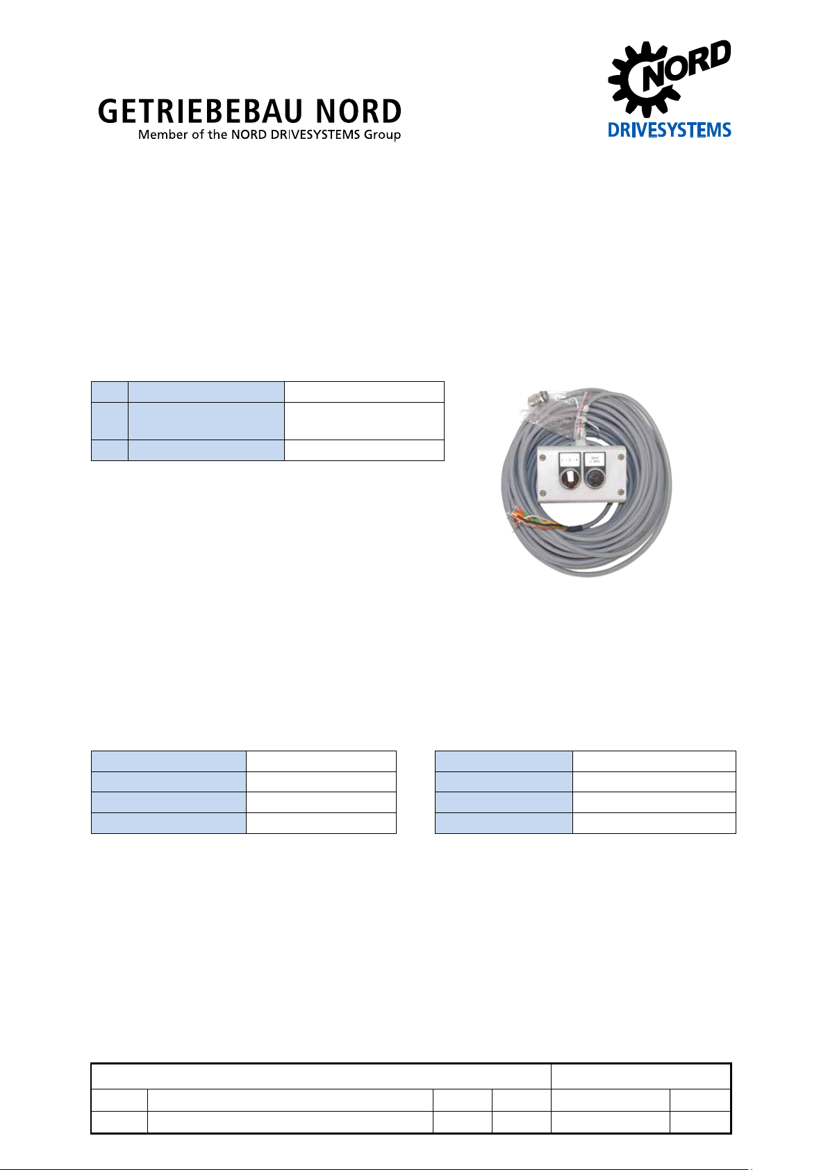
Control Box / Manual control unit
Scope of supply
1 x Control box SK POT1-2
Incl. connection cable shielded,
open cable ends
1 x Cable gland M16
Field of use
Manual control unit (wall mounting possible) for the control of NORD frequency inverters with an
enable signal and set point value. It is desig ned for permanent connection to th e frequency inverter.
According to the inverter type, appropriate interfaces are available, or are available as options.
Technical Data
Temperature range 0 °C … 40 °C Connection cables approx. 20 m long
Protection class IP66 Weight approx. 2.0 kg
Direction selector switch Left - OFF - Right Dimensions [mm]* L x W x H: 120 x 80 x 80
Potentiometer 0 … 100 % (0 …10 V)
Pos: 3 /Technis c h e Inf ormation en/ Bedienb o xe n [S K P OT 1-...]/Montag e [SK POT1-x] @ 3\mod_1367480195951_388.docx @ 64511 @ 5 @ 1
Control box SK POT1-2
1.0 издание первое 3313 Rck TI 278910140 GB
version reason for change(s) issue name document speech
Control box – SK POT 1 -2
4 screws on the mounting surface (fastening material not included in the scope of
Reassemble the control unit and fasten it to the lower section of the
The control box is designed for
1), this must be
connected to the Analog Ground
ble wire end
Installation
The control box is des igned as a handheld version, but it can also be permanently installed in the
vicinity of the frequency inverter.
Installation location Wall surface near to the inverter
Mounting
delivery)
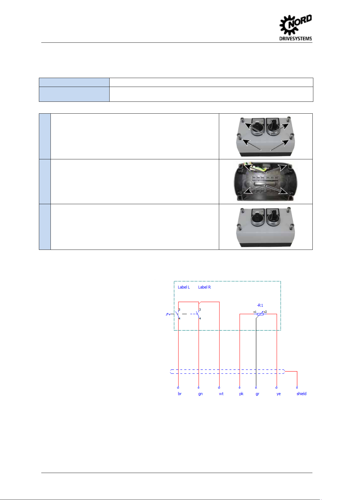
1. Unscrew the screws on the front side and remove the cover.
2. Mount the lower section of the housing at the required location with
suitable fastening materia l.
Spacing of the fastening holes:
X-axis (horizontal): approx. 106.5 mm
Y-axis (vertical): approx. 66.5 mm
3.
housing using the 4 screws (pay attention to the seal).
Pos: 4 /Technis c h e Inf ormation en/ Bedienb o xe n [S K P OT 1-...]/Anschlüss e [SK POT1-...] @ 3\mod_1367912341490_388.do cx @ 64681 @ 5 @ 1
Connections
permanent connectio n to the frequency
inverter. For this, the open cable ends
of the control box must be connected
directly to the appropriate terminals of
the frequency inverter. If there is a cable
shield (not SK POT1-
(AGND) of the frequency inverter. If
necessary, use dou
sleeves.
Pos: 5 /Technis c h e Inf ormation en/ Bedienb o xe n [S K P OT 1-...]/Sc hni t t st ellen Frequ enz umrichter [S K POT1-x] @ 3\mod_1367913796919_388.docx @ 64756 @ 5 @ 1
2 TI 278910140 - 3313
 Loading...