

Page 1
IO-Extension
SK EBIOE-2
1.0
Erstausgabe / first issue
4612
Rck
TI 275900210
GB
version
reason for change(s)
issue
name
document
speech
SK EBIOE-2
Part Number 275 900 210
IO Extension
NOTICE
Validity of this document
This document is only valid in conjunction with the operating manual supplied for the respective frequency
inverter. It is essential that all the relevant information is available for the safe commissioning of this module and
the frequency inverter.
1 x
Module
SK EBIOE-2
1 x
Snap-on rail bus
connector
5-pole
Temperature range
0 °C … 40 °C
Vibration resistance
2M1
Temperature class
Class 3K3
Firmware version
V1.2 R0
Protection class
IP20
Dimensions [mm]
HxWxD 114 x 22.5 x 105
Name
Terminal
Data
Module power supply (load capacity)
40/44
24 VDC ± 20 %, reverse polarity protected
(≤ 3 A)
Power consumption of module
40/44
140 mA … 340 mA (according to load on
terminal 43)
Digital input - provision of 24 VDC
40/43
≤ 200 mA (output)
Digital input - operating range
C1 … C4
Low: 0 V … 5 V, High: 15 V … 30 V
Digital input - specific information
C1 … C4
Ri = 8,1 kΩ, input capacitance: 10nF
Scan rate 1 ms, reaction time 1 ms
Digital output - 24 VDC power supply
20/50
≤ 1000 mA (input)
Digital output - operating range
B1, B2
Low = 0 V, High = 24 V; max. 500 mA
Analog input - reference voltage
11
10 VDC ±0,1 V, ≤ 20 mA (output)
Analog input - differential input version
13/14; 15/16
Resolution: 12 Bit, accuracy: 0.1 V
Pos: 1 /Technische Informationen/IO - Er weiterung/SK EBIOE-2 / 275900210 /SK E BIOE-2 / 275900210 / Basisinformatio nen [SK EBIOE-2] @ 2\mod_1352386981 855_388.docx @ 50903 @ 6666 @ 1
Technical Information / Datasheet
Scope of Supply
Field of use
External IO extension for snap-on rail mounting of the SK 54xE (SK 2xxE also permissible). This can
be connected to the inverter via the CAN bus. Four digital inputs, 2 digital outputs, 2 analog inputs and
1 analog output are available. Further IO modules can be connected via a snap-on rail bus connector.
Technical Data
Page 2
IO-Extension – SK EBIOE-2
Name
Terminal
Data
Analog output - load capacity
17
≤ 10 mA (Mode: 0/2 … 10 V)
≤ 20 mA (Mode: 0/4 … 20 mA, at 5 V)
Analog output - specific information
17
Resolution: 10 Bit, accuracy: 0.25 V
RJ45 - current capacity
RJ45 7/8
≤ 1200 mA
Installation location
Inside a suitable switching cabinet
Mounting
Mounting on snap-on rail (TS 35)
Terminals
Screw terminals
6 terminal blocks, each with 4 connections, (5 mm spacing)
Cable cross section
0,14 … 2,5 mm
AWG 14-26
PE connection
via snap-on DIN
rail
The snap-on rail must be earthed
Snap-on rail bus connector
Plug connector
For the serial installation of up to 8 SK EBIOE-2 modules
RJ45
RJ45 - socket
For connection via RJ45 connection cable
Terminal
Contact
Designation
Description
X1
Top
position
40
GND/0V
Reference potential (0 V / GND)
44
VI 24V
Supply voltage (+24 V - in)
78
SYS-
System bus data cable -
77
SYS+
System bus data cable +
X2
Top
position
12
AGND/0V
Analog Ground (internally connected to terminal 40)*
15
AIN2-
Analog input 2, negative
16
AIN2+
Analog input 2, positive
17
AOUT
Analog Out
X3
Top
position
12
AGND/0V
Analog Ground (internally connected to terminal 40)*
13
AIN1-
Analog input 1, negative
14
AIN1+
Analog input 1, positive
11
VO 10V
10 V Reference voltage
X4
Bottom
position
50
VI 24V2
Supply voltage (+24 V - in) for digital outputs
B1
DOUT1
Digital output 1
B2
DOUT2
Digital output 2
20
GND2/0V2
Reference potential (0 V / GND) of digital outputs
X5
Bottom
position
43
VO 24V
Supply voltage for digital inputs (+24 V - out)
C3
DIN3
Digital input 3
C4
DIN4
Digital input 4
40
GND/0V
Reference potential (0 V / GND)
X6
Bottom
position
43
VO 24V
Supply voltage for digital inputs (+24 V - out)
C1
DIN1
Digital input 1
C2
DIN2
Digital input 2
40
GND/0V
Reference potential (0 V / GND)
X7
Front
position
RJ45 - 1
SYS +
System bus data cable +
RJ45 - 2
SYS -
System bus data cable -
RJ45 - 7
GND/0V
Reference potential (0 V / GND)
RJ45 - 8
24 V
Supply voltage (+24 V – in / out)
X8
Rear
position
Snap-on rail bus
connector
Connection of voltage supply and system bus to a further
SK EBIOE-2 module
* AGND/0V is internally connected to the reference voltage of the module GND/0V via a special
component. In order to prevent damage to the module or faults in the analog signals, the two contacts
must not be bridged
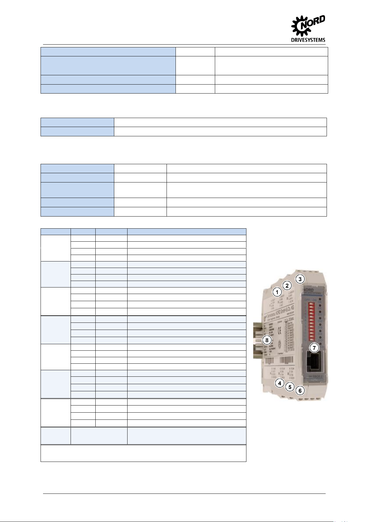
1 … 8 =
X1 … X8
Installation
Pos: 8 /Technische Informationen/IO - Er weiterung/Anschlüsse [SK EBIOE-2] @ 2\ mod_1353314658836_388.docx @ 512 01 @ 6 @ 1
Connections
2 TI 275900210 - 4612
Page 3

IO-Extension – SK EBIOE-2
NOTICE
Load on the RJ45 socket
The load on the contacts of the RJ45 socket must not exceed 1.2 A. When setting up a correspondingly large
network with frequency inverters and IOE modules, it may be necessary to set up two circuits in order to prevent
overload.
Terminal
Function
Device
X1
Supply / System bus
SK EBIOE-2
X2
AIN 2 / AOUT
X3
AIN 1
X4
DOUT
X5
DIN 3 / 4
X6
DIN 1 / 2
X7
Supply / System bus
X8
Supply / System bus
X9
Supply / System bus
SK
54xE
X10
Supply / System bus
RJ45 WAGO connection module
Part. No.: 278910300
Control
voltage
source
Digital input
Digital output
External
supply
GND/0V
VI 24V
DIN
DIN
GND2/0V2
DOUT
VI 24V2
GND2/0V2
VI 24V
DOUT
VI 24V2
GND/0V
Internal supply
GND/0V
VO 24V
DIN
DIN
GND2/0V2
VO 24V
DOUT
VI 24V2
GND/0V
Schematic circuit diagram of electrical connection
(Terminal designations in example) Frequency inverter SK 54xE)
Pos: 12 /Technische Informationen/IO - Erweiterung/Anschlussbeispiele [IOE Allg emein] @ 2\mod_1352736753713_388. docx @ 51105 @ 6 @ 1
Connection examples
The following connection examples are generally applicable for NORD IO modules. The number or
type of the available IOs and their configuration on the terminal rail varies according to the module.
The actual availability or the designation of the individual contacts should be obtained by reference to
the description of the connections. The technical data (e.g. load capacity) must be taken into account.
Digital signals
TI 275900210 - 4612 3
Page 4

IO-Extension – SK EBIOE-2
Signal type*
Analog / Differential input
Analog output
0/2 … 10 V
0/4 … 20 mA
-10 … 10 V**
VO 10V
AGND/0V
AIN AIN +
AGND/0V
AOUT
Potentiometer
(10 kΩ)
0 … 10 V
VO 10V
AGND/0V
AIN AIN +
R=10kΩ
* The relevant IOs must be configured via DIP switches according to the form of the signal
** Analog input only
Note
Broadcast mode
In "Broadcast mode, which is activated via the parameter (P162), the module can access up to 4 inverters in
parallel. Therefore the frequency inverters jointly access the I/Os and evaluate the input signals according to their
own parameterisation. Output signals from the frequency inverters which are sent to the common IO module are
linked by a logical "OR" within the module. i.e. a digital output is set as soon as one of the four frequency inverters
addresses it. In addition, the highest analog value is provided via the analog output of the IO extension.
Analog signals
Pos: 13 /Technische Informationen/IO - Erweiterung/Konfiguration [IOE Allgemein] @ 2\mod_1352388400441_388.docx @ 50928 @ 6 @ 1
Configuration
Configuration of the module is mainly performed via the DIP switches. The DIP switches are read after
a "power on" of the module. A change to the DIP switch during operation has no effect.
The system bus must be terminated at both of its physical ends (if necessary set the "System bus
termination resistor" DIP switch).
4 TI 275900210 - 4612
Page 5

DIP switches
Function
DIP-Switch
Meaning
DIP-Switch
Combinations
Assignment
Signal
(DIP-No.)
BIT2
BIT1
BIT0
System bus
termination
resistor
S-Bus Term.
(01)
0 1 not set
setting
Addressing
system bus
S-Bus Adr. Bit 0
(02)
0
0
1
1
0
1
0
1
Adr. 20 (for FI 0 Adr. 32)*
Adr. 21 (for FI 1 Adr. 34)*
Adr. 22 (for FI 2 Adr. 36)*
Adr. 23 (for FI 3 Adr. 38)*
S-Bus Adr. Bit 1
(03)
Analog input
AIN1
Ain1 Mode Bit 0
(04)
0
0
0
1
1
0
0
1
0
0
0
1
0
0
1
0 … 10 V
2 … 10 V
-10 … 10 V
0 … 20 mA
4 … 20 mA
Ain1 Mode Bit 1
(05)
Ain1 Mode Bit 2
(06)
Analog input
AIN2
Ain2 Mode Bit 0
(07)
0
0
0
1
1
0
0
1
0
0
0
1
0
0
1
0 … 10 V
2 … 10 V
-10 … 10 V
0 … 20 mA
4 … 20 mA
Ain2 Mode Bit 1
(08)
Ain2 Mode Bit 2
(09)
Analog output
AOUT
Aout Mode Bit 0
(10)
0
0
1
1
0
1
0
1
0 … 10 V
2 … 10 V
0 … 20 mA
4 … 20 mA
Aout Mode Bit 1
(11)
Mode
Second - IOE
2nd IOE Mode
(12)
0 1 First SK-…-IOE on FI
Second SK-…-IOE on FI
* With DIP12 = ON: Address 10 … 13 instead of 20 … 23
DS
(Device State)
DE
(Device Error)
Meaning
Long flashing = 0.5 s on / 1 s off
Short flashing = 0.25 s on / 1 s off
OFF
OFF
Technology unit not ready, no control voltage
ON
OFF
Technology unit ready, no error, at least one frequency inverter is communicating via the system bus
ON
Short flashing
Technology unit ready, however
• One or more of the connected frequency inverters is in fault status
Long flashing
OFF
Technology unit ready and at least one further participant is connected to the system bus, but
• No frequency inverter on the system bus (or connection interrupted)
• Address error for one or more system bus participants
Long flashing
Short flashing
Flash interval
1 x - 1s pause
System bus is in status "Bus Warning"
• Communication on system bus interrupted or
• No other participant present on the system bus
Long flashing
Short flashing
Flash interval
2 x - 1s pause
• System bus is in status "Bus off" or
• The system bus 24V power supply was interrupted during operation
Long flashing
Short flashing
Flash interval
3 x - 1s pause
• No system bus 24V power supply (system bus is in status "Bus off")
Long flashing
Short flashing
Flash interval
4 x - 1s pause
Module error
• EEPROM error
Long flashing
Short flashing
Flash interval
5 x - 1s pause
Module error
• AOUT error (analog output)
• DIP switch configuration error
OFF
Short flashing
Flash interval
1…7 - 1s pause
System error, internal program sequence interrupted
• EMC interference (observe wiring guidelines!)
• Module faulty
IO channel
Display
Meaning
IO channel
Display
Meaning
DI 1
ON
High potential DIN1
DO 1
ON
High potential DOUT1
DI 2
ON
High potential DIN2
DO 2
ON
High potential DOUT2
DI 3
ON
High potential DIN3
DI 4
ON
High potential DIN4
DI 3/4, DO 1/2
Available according to the type of IO
module
IO-Extension – SK EBIOE-2
Pos: 14 /Technische Informationen/IO - Erweiterung/LED Anzeigen [IOE Allgemein ] @ 2\mod_1352390573890_388.docx @ 51028 @ 6 @ 1
LED Displays
Pos: 15 /Technische Informationen/IO - Erweiterung/Fehlermeldungen [IOE Allge mein] @ 2\mod_1352389805965_388.doc x @ 50953 @ 6 @ 1
TI 275900210 - 4612 5
Page 6

IO-Extension – SK EBIOE-2
Error
Meaning
Comments
1000
EEPROM error
EMC fault, module defective
1030
System bus OFF
No 24 V supply to bus, connections not correct
2000
DIP switch changed
DIP switch configuration changed during operation
2001
DIP switch configuration incorrect
Invalid DIP switch settings
2010
Error at analog output
Overload, reference voltage, short-circuit, calibration error
2020
Inverter does not support the module
Incorrect inverter type connected
Parameter
Meaning
Comments
(P514)
Bus speed
5 (= 250 kBaud)
(P515 [-01])
Bus address
FI 1 = 32
FI 2 = 34
FI 3 = 36
FI 4 = 38
(P480 [-01 …-08])
DIN function of the SK EBIOE
Possible settings according to (P420)
(P481 [-05 …-08])
DOUT function of the
SK EBIOE
Possible settings according to (P434)
(P400 [-03 …-06])
AIN function of the SK EBIOE
Possible settings according to (P400)
(P418 [-02 …-03])
AUT function of the SK EBIOE
Possible settings according to (P418
Parameter
Meaning
Comments
(P150)
Set relays
Set DOUT directly or control via BUS
(P152)
Factory setting
Reset the module parameters, calibrate AOUT
(P153 [-01 …-02])
Minimum system bus cycle
Reduction of bus load due to the module
(P160)
Set analog output
Set AOUT directly or control via BUS
(P161 [-01 …-09])
Filter time
Debounce or round input signals
(P162)
Send broadcast
Activate Broadcast mode (control of several
inverters by this module)
(P163)
Invert analog output
Invert analog signal
(P170 [-01 … 02])
Present errors
Display of module errors
(P171 [-01 … 03])
Software version
Firmware version / Revision
(P172)
Configuration
Module type
(P173)
Module status
Status of system bus or connected FI
(P174)
Status of digital inputs
Display of DIN switching status
(P175)
Relay status
Display of DOUT switching status
(P176 [-01 … 03])
Actual voltage
Voltage level of analog signals
Document
Name
Document
Meaning
NORD CON
Parameterisation and diagnostic software
BU 0200
SK 2xxE frequency inverter manual
BU 0000
Description of NORD CON software
BU 0500
SK 5xxE frequency inverter manual
BU 0040
ParameterBox manual
Error messages
Error messages for the module - the present or archived messages for the last error - can be read out
via the module parameter (P170) (see Parameterisation).
Pos: 16 /Technische Informationen/IO - Erweiterung/Parametrierung [IOE Allgemein ] @ 2\mod_1352389903587_388.docx @ 50978 @ 6 @ 1
Parameterisation
Inverter: In order to establish communication between the inverter and the IOE module, the following
inverter parameters must be changed.
IO extension: The module provides a selection of parameters for setting or displaying special
operating values. The parameters can be changed with the aid of the NORDCON software or with a
ParameterBox. Communication is only possible via an SK 54xE or SK 2xxE which is connected to the
module.
Pos: 17 /Technische Informationen/IO - Erweiterung/Weiterführende Dokumentati onen und Software [IOE Allgemein] @ 2\ mod_1352390057120_388.docx @ 510 03 @ 6 @ 1
Further documentation and software (www.nord.com)
=== Ende der Liste für Textmarke Inhalt ===
6 TI 275900210 - 4612
 Loading...