

Page 1
ATTENTION
This document is only valid in combination with the operating instructions for the relevant frequency inverter. All
Pos: 1 /Technis c h e Inf ormation en/ SK xUx - Bus - Er weiterung en/EtherN et/IP/SK TU 4-EIP / 27 5281119 / B asisinform ationen [S K TU4-EIP] @ 3\ mod_1362990949241_388.docx @ 61372 @ 555 @ 1
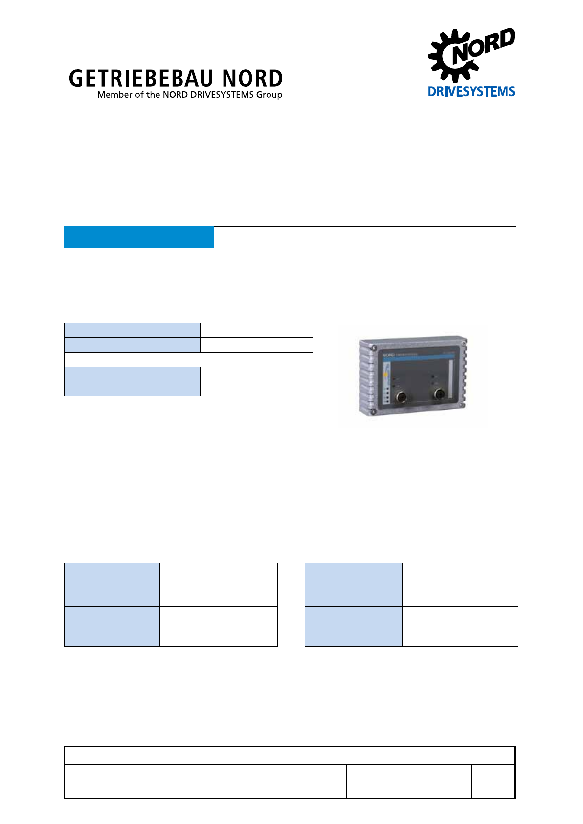
SK TU4-EIP
Technical Information / Datasheet
Part number: 275 281 119
EtherNet/IP® - External bus – interface
Validity of the documents
of the information that is relevant for a safe start-up of this module and the frequency inverter is only available
under these conditions.
Scope of delivery
1 x Module SK TU4-EIP
4 x Hexagon socket M4 x 40 mm
Accessories required:
1 x Bus connection unit SK TI4-TU-BUS
TI 275280000 (Part No. 275 280 000)
Usage area
External technology box for connecting distributed frequency inverter (SK 180E … SK 2xxE) to a
EtherNet/IP field bus. The module can be fitted to or in the immediate vicinity of the frequency
inverter. It is connected via the system bus with the inverter and can respond directly with up to
4 frequency inverters. 8 digital inputs and 2 digital outputs are available.
Technical data
Module
Temperature range -25 °C … 50 °C Vibration resistance 3M7
Temperature class Class 3k3 Firmware version V1.1 R1
Protection class IP55 Hardware version AA
Supply voltage 24 V ± 20 %, ≈ 100 mA
Dimensions [mm]* H x W x D: 95 x 136 x 99
Reverse polarity
protected
* module fitted to BUS-connection unit
Depth: 108mm with covers on M12
-connection
EtherNet/IP Bus module SK TU4-EIP
1.1 LED - displays, technical datas, Error 10.9 4913 Rck TI 275281119 GB
version reason for change(s) issue name document speech
Page 2
EtherNet/IP Bus module – SK TU4-EIP
DIP switches, module parameters, BOOTP and DHCP
diagnosis socket on the device (if available) and possibly
Digital input - working area Low: 0 V … 5 V, High: 15 V … 30 V
Digital input - specif ic dat a Ri = 10 kΩ, input capacity: 10nF, reaction time 1 ms, inputs
according to EN 61131-2 type 1
Digital output - 24 VDC power supply ≤ 400 mA (input)
Digital output - working area Low = 0 V, High = 24 V; max. 200 mA
Bus specification
EtherNet/IP Max. 100 MBaud Cable Min. Ethernet CAT-5
Electrical isolation 500 V
Max. cable length 100 m between two
eff
modules
Bus connection 2 x M12 Shield via M12 direct to PE
Bus termination Takes place automatically PE connection via PE screw connection
Status display 8 LEDs in the terminal box
Topology* Star*, ring, linear bus
* additional switch for "star" topology required
Performance
Update interval for process data between module and frequency inverter ≤ 5 ms
Parameter read access to frequency inverter ≈ 15 ms
Parameters write access with storage on EEPROM ≈ 25 ms
Cycle times ≥ 1ms
Pos: 6 /Technis c h e Inf ormation en/ SK xUx - Bus - Er weiterung en/EtherN et/IP/Mer kmale [EIP Al lgemein] @ 3\mod_1362996549668_388.docx @ 61397 @ 5 @ 1
Module features
IO messages (process data connections) One "Exclusive Owner“
Max. 2 “Listen Only” connections
Type "Cyclic", min cycle time 1 ms
Explicit messages Yes
UCMM Supported
DLR Supported
Switch with two ports integrated
Addressing via
possible
Access for NORD diagnosis tool via
via frequency converter and
Ethernet protocols UDP or TCP/IP
Pos: 7 /Technis c h e Inf ormation en/ SK xUx - Bus - Er weiterung en/Allgem ein - System übergreif end/Montag e [SK TU4- xxx-xxx] @ 2\mod_1353315135994_388.docx @ 51251 @ 5 @ 1
Installation
The module m us t be attac h ed to t he s u it a ble co nn ec tio n un it (S K TI4-TU- …) and connected using t h e
four M4 x 40 mm provided hexagon s ocket collar sc rews. Installation det ails can be found in the data
sheet for the relevant connection units.
Pos: 10 /T echnische I nformatio ne n/ SK xUx - Bus - Erw eiterunge n/Allgemei n - Systemüb ergreifen d/Anschlüss e - Etherne tseite - Var iante M12 [ SK TU4-...E IP/ECT/PO L/Anschlüss e - Ethern etseite - Var iante M12 [ SK TU4-... EIP/ECT/POL/PNT(-M 12)...-C)] @ 4\mod_1385383150995_388.docx @ 106697 @ 5 @ 1
2 TI 275281119 - 4913
Page 3
PIN
Signal
Description
1
TX+
Transmission Data +
2
RX+
Receive Data +
3
TX-
Transmission Data -
4
RX-
Receive Data -
Potential
Contact
Designation
Description
1
24V
Supply potential (+24 V, ≤ 200 mA)
2
24V
Supply potential (+24 V, ≤ 200 mA)
3
DIN5
Digital input 5
4
DIN7
Digital input 7
5
DIN6
Digital input 6
6
DIN8
Digital input 8
7
0V
Reference potential (0 V / GND)
8
0V
Reference potential (0 V / GND)
9
24V
Supply potential (+24 V, ≤ 200 mA)
10
24V
Supply potential (+24 V, ≤ 200 mA)
11
24V
Supply voltage (+24 V)
12
24V
Supply voltage (+24 V)
13
24V
Supply voltage (+24 V)
14
SYS +
System bus data line +
15
0V
Reference potential (0 V / GND)
16
SYS -
System bus data line -
18
0V
Reference potential (0 V / GND)
19
DIN1
Digital input 1
20
DIN3
Digital input 3
21
0V
Reference potential (0 V / GND)
22
0V
Reference potential (0 V / GND)
23
24V
Supply voltage (+24 V)
24
24V
Supply voltage (+24 V)
25
DIN2
Digital input 2
26
DIN4
Digital input 4
27
0V
Reference potential (0 V / GND)
28
0V
Reference potential (0 V / GND)
29
24V
Supply voltage (+24 V)
30
24V
Supply voltage (+24 V)
31
VI 24V2
Supply potential (+24 V - in) of the digital outputs
32
0V2
Reference potential (0 V / GND) of the digital outputs
33
DOUT1
Digital output 1 (+24 V, ≤ 200 mA)
34
DOUT2
Digital output 2 (+24 V, ≤ 200 mA)
35
0V2
Reference potential (0 V / GND) of the digital outputs
36
0V2
Reference potential (0 V / GND) of the digital outputs
RJ12 - 1
RS485_A
Data cable RS485
RJ12 - 2
RS485_B
Data cable RS485
RJ12 - 3
GND
Reference potential (G ND )
RJ12 - 4
RS232_TxD
Data cable RS232
RJ12 - 5
RS232_RxD
Data cable RS232
RJ12 - 6
24 V
Supply voltage (+24 V)
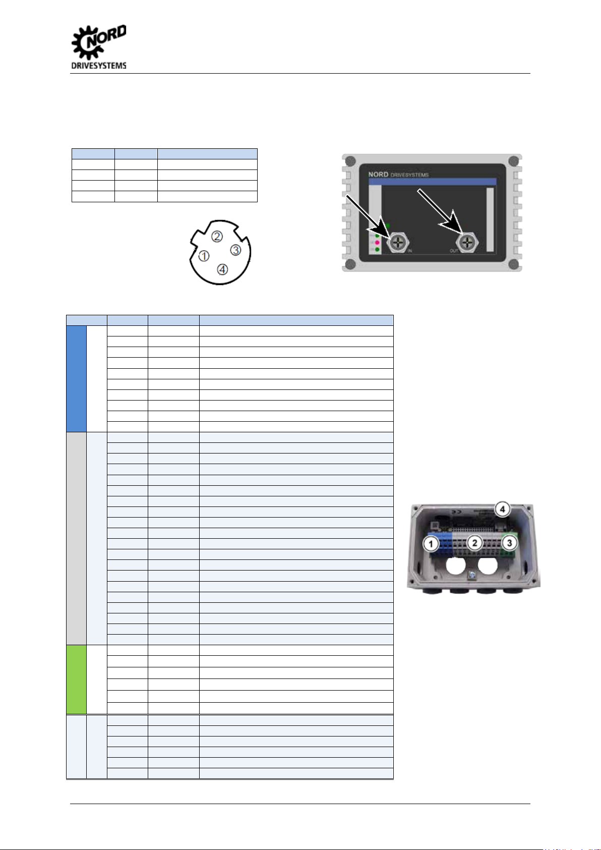
Connections
The two Ethernet lines are connected exclusively via the two M12 sockets on the front. If the module is
the final subscriber on the line, one M12 socket can remain unoccupied. The use of EMC screw
connections is recommended.
EtherNet/IP Bus module – SK TU4-EIP
PIN assignment
M12-4 socket
("D“- coded):
Pos: 11 /T echnische I nformatio nen/SK xUx - Bus - Erweit erungen/Al lgemein - S ystem übergreife nd/Anschl üsse - Klem menleiste [ SK TU4(-C) - Et herNet Baugr u p pen allgemei n] @ 3\mod_1362998963057_388.docx @ 61424 @ @ 1
The connection to other signal and control lines takes place via the BUS - connection units.
1
Digital inputs
17 0V Refere nc e pot en ti al (0 V / GND)
2
System bus level and digital inputs
3
Digital outputs
4
Diagnosis
TI 275281119 - 4913 3
Page 4

EtherNet/IP Bus module – SK TU4-EIP
VI 24V
GND/0V
SYS +
SYS -
24V
GND/0V
SYS +
SYS -
DIP switches
Meaning
X X X 0 0 0 0 0 0 0 0 X 0 X X X 0 0 0 0 0 0 0 1 X 1 X X X 0 0 0 0 0 0 1 0 X 2
X X X 0 - - - - - - - X - X X X 1 1 1 1 1 1 1 1 X
255 0
System bus terminating resistor not set
1 System bus terminating resistor set
Access rights for remote maintenance
0 Only read access to parameters possible.
1 Read and write access to param et ers possible.
0 No control possible.
1 Control is possible.
0 TCP/IP open connection.
1 Secure TCP/IP connection.
switch and is controlled in parameter P185.
1 … 12
ON
OFF
Schematic diagram - electrical connection
(Terminal designation on example of NORD frequency inverter SK 180E … SK 2xxE)
SK TI4-TU4 BUS SK 180E … SK 2xxE
Pos: 14 /T echnische I nformatio nen/SK xUx - Bus - Erweit erungen/Et herNet/IP /Konfigurati on [SK TU 4-EIP(-C)] @ 3\ mod_1363014748945_388.docx @ 61506 @ 5 @ 1
Configuration
The basic configurat ion of the module prim arily takes place via its DIP - switch es. The DIP - switch
settings are read after a "Power On" of the module.
12 11 10 9 8 7 6 5 4 3 2 1
Address
1. System bus (DIP 1)
The system bus mus t be terminated at both physica l
ends.
2. IP address (DIP 2 – 9)
The final byte of the IP address can be set vi a this
However, parameter P165 must be s et to the defau lt
setting (setting value "0").
3. Access rights for remote maintenance (DIP 10 – 12)
The module an d the connected freque ncy converter
can be accessed via Ethernet protocols TCP and
UDP via remote maintena nce. The type of acces s is
determined via the DIP - switch with inputs 10 to 12.
Pos: 17 /T echnische I nformatio nen/SK xUx - Bus - Erweit erungen/Et herNet/IP/ LED Anzeig en [SK TU 4-EIP(-C)] @ 3\mod_1363770069294_388.docx @ 61791 @ 5 @ 1
4 TI 275281119 - 4913
Page 5

No.
Name
Colour
Meaning
DS
green
Device status
DE
red
Device error
MS
(Module status)
Meaning NS
(Network status)
Meaning
OFF
No operating voltage
OFF
No operating voltage
Flashing gree n
Flashing gree n
available
green
Module working correctly
green
CIP connection(s) available
has a time-out error
red
Unrecoverable error
red
Dual IP whose IP address is alrea d y bei ng
used by the module
Flashing
red/green
Power up, self test
Flashing
red/green
Power up, self test
Link
(Green LED)
Activity
(Yellow LED)
Meaning
OFF
OFF
• Module not ready, no control voltage.
ON
OFF
• No bus activity available
ON
Flashing
• Bus connection (cable connection) to another Ethernet device availabl e
Meaning
OFF
OFF
Module not ready, no control voltage.
ON
OFF
Module ready, no error, at least one frequency inverter is communicating via the system bus
• One or more of the connected frequency inverters has fault status
Long flashing
OFF
Module ready and at least one other participant is connected to the system bus, but
• Software incompatible (module software and FI software do not match - update required)
Long flashing
Short flashing
System bus is in status "Bus Warning"
• Frequency inverter has no supply voltage
Long flashing
Short flashing
System bus is in status "Bus Off"
Long flashing
Short flashing
4
Module error
LED displays
The operating status of the module is visualised using LED indicators.
MS dual (red/green) Module status
NS dual (red/green) Network status
1
Link green Link
2
EtherNet/IP Bus module – SK TU4-EIP
Activity yellow Activity
Pos: 20 /T echnische I nformatio nen/SK xUx - Bus - Erweit er u ng e n/EtherN et/ I P /L ED Anzeige n- E therNet/IP spezifische LED [EIP Allgemein] @ 3\mod_1363774926130_388.docx @ 61840 @ @ 1
EtherNet/IP-specific LEDs
Module not configured
Flashing red
Minor error, faulty configuration
(Blinking)
Pos: 21 /T echnische I nformatio nen/SK xUx - Bus - Erweit erungen/Al lgemein - S ystemüberg reifend/LED Anzeigen- N ORD spezifische LED [EIP / POL / ECT / PNT Allgemein] @ 3\mod_1363773424248_388.docx @ 61815 @ @ 1
NORD-specific LEDs
IP address configured but no CIP connection
Flashing red
Time-out, an "exclusive owner connection"
• No bus connection (check cable connection)
• Bus connection (cable connection) to another Ethernet device available
• Bus activity available
DS
(Device status)
ON Short flashing
DE
(Device error)
Long flash = 0.5 s on / 1 s off
Short flash = 0.25 s on / 1 s off
Module ready, but
• no frequency inverter connected to system bus (connection may be interrupted)
•
one or more system bus clients has address error
Flash interval
1 x - 1s pause
Long flashing Short flashing
Flash interval
2 x - 1s pause
Flash interval
• Communication on system bus disrupted
•
No other clients available on system bus
•
Module not inserted correctly or no connection to the system bus
System bus is in status "Bus Off"
•
the system bus 24V power supply was interrupted during operation
• No system bus 24V power supply
3 x - 1s pause
Flash interval
x - 1s pause
OFF Short flashing
Flash interval
1…7 - 1s pause
TI 275281119 - 4913 5
• see parameter P170
System error, internal program sequence interrupted
EMC interference (obs er ve wi rin g guidelines!)
•
• Module defective
Page 6

EtherNet/IP Bus module – SK TU4-EIP
Error
Meaning
Remarks
100.0
EEPROM error
EMC fault, module defective
102.0
Timeout
via P151/P513 monitoring
103.0
System bus BUS OFF
No 24V supply to the bus, connections not correct
104.0
Module temperature > 97°C
SK CU4-… only, zpermissiv e internal temperature of the mo dule
550.1
DIP switch error
The DIP switches (IP address) could not be read correctly
560.0 …
Internal error
Module not r eady
561.0
General network error
561.1
Ethernet Watchdog timeout
561.3
IP address error
IP address of the module has been doubly assigned
563.0
Firmware version incompatible
The firmware version cannot be used for the device
564.0
MAC address error
Error
(E010)
Meaning
Remarks
10.0
Connection error
Contact to SK xU4 lost
10.1
ASIC errors
Communication to Ethernet - ASIC lost
• Switch-off of the supply voltage
10.2
Ethernet/IP Watchdog timeout
Telegram transfer error
• Check the Watchdog time
10.4
IP address error
IP address of the module has been doubly assigned
• for SK CU4-… e.g.: Module temperature > 97°C
10.6
Bus cable fault
Bus cable connection interrupted
10.8
The connection between the inverter
Only SK TU3 module
10.9
Module missing (P120)
Only SK xU4 module
Pos: 22 /T echnische I nformatio nen/SK xUx - Bus - Erweit erungen/Al lgemein - S yst emübergr ei fe n d/Fehler mel dungen Ether net Baugru pp en allgemein [ SK x U x-EIP / POL - Allge mei n] @ 3\mod_1363779786491_388.docx @ 61865 @ 5 @ 1
Error messages
Error messages fr om the m odule - present error s or archived m ess ages relating t o the last error - can
be read out via the module par ameter (P170). The error messages are lost if the m odule is switched
off.
exceeded for approx. 60 sec.
560.9
561.2 Bus cable fault Bus cable connection interrupted
Errors which occur in relation to the module are depicted as follows in the error memory of the
frequency inverter (P700 / P701).
10.3 Timeout by P151/P513 Telegram transfer error
10.5 Internal error Module not r eady,
and the module had a timeout
Pos: 23 /T echnische I nformatio nen/SK xUx - Bus - Erweit erungen/Al lgemein - Systemübergreifend/Parameter [SK xU x-. .. Allgemei n - Frequen zumrichter ] @ 4\mod_1384953855694_388.docx @ 105781 @ 5 @ 1
• Check the connections and links, program sequence and
Bus Master
•
Check the connections and links
6 TI 275281119 - 4913
Page 7

Parameter [-Array]
Meaning
Remarks
P120 [-01]
Option monitoring
"Auto“ (default setting)
Only SK xU4
SK xU4-… on SK 180/SK 2xxE: "System bus"
P510 [-01 … -02]
Setpoint source
"Auto“ (default setting)
P513
Time-out
Monitoring of the SK TU3 bus module
Only SK 5xxE
P543 [-01 …-03 (-05)]
and P543 … P545
Bus actual values (1 …3 (… 5))
Possible settings according to (P418)
P546 [-01 …-03 (-05)]
Bus target values (1 …3 (… 5))
Possible settings according to (P400)
P700 [-01] / P701
Current / last failures
Information parameters
P740 / P741
Process data bus In / Out
Information parameters
P745
Module version
Information parameters
Only SK TU3
P745
Module status
Information parameters
Only SK TU3
P748
CANopen / System bus status
Information parameters
Parameter [-Array]
Meaning
Remarks
-TU3-
-TU4-
-CU4-
P150
Set relays
Set DOUT directly or control via BUS
X
P151
External bus time-out
Monitoring of SK xU4 bus module;
X X
P152
Factory setting
Reset module parameters
X X X
cycle
caused by the module
P154 [-01 …-02]
Access to option card I/O
Administration of r ead and write rights to the IO of
the module
X X
P161 [-01 …-04]
IP subnet mask
X X X P164 [-01 …-04]
IP Gateway
X X
X
(default setting)
P169
Password
X X
X
P170 [-01 … -02]
Present errors
Displaying module errors
X X X
P171 [-01 … -03]
Software version
Firmware version / Revision
X X X
P172
Configuration
Module type
X X X
P173
Module status
Status of system bus or connected FI
X X X
P174
Status of digital inputs
Image of the switching status of DIN
X X
P175
Digital output state
Image of the switching status of DOUT
X
P176 [-01 … ]
Process data bus In
Information parameter
X X X
P177 [-01 … ]
Process data bus Out
Information parameter
X X X
P178
Internal temperature
Information parameter
X
P180 [-01 … -02]
Active assembly
Information parameter
X X X
P181 [-01 … -06]
MAC address
Information parameter
X X X
P185 [-01 …-04]
Present IP address
Information parameter
X X X
P186 [-01 …-04]
Current IP subnet mask
Information parameter
X X X
Parameters
Frequency inverter: The following frequency inverter parameters must be adapted for setting up
communication between the frequency inverter and the bus module (for details see frequency
converter manual).
EtherNet/IP Bus module – SK TU4-EIP
P509 Control word source
and P546 … P548
Pos: 24 /T echnische I nformatio nen/SK xUx - Bus - Erweit erungen/Et herNet/IP /Parameter [EIP Allge mein] @ 3\mod_1363788177458_388.docx @ 61890 @ @ 1
SK TU3-… on SK 5xxE: "Ethernet TU”
BUS module: The module provides a selection of appropriate parameters for setting or displaying
special operating values. Parameters can be adapted using the NORDCON software or an
SK PAR-3H / -3E param eter box. All parameter s can still be read and written via Ether Net/IP by the
bus master.
P153 [-01 …-02] Minimum system bus
Reduction of the bus load on the system bus
X X
P160 [-01 … 04] IP address Alternative to setting the array value [-04]: DIP
P165 Addressing mode
P166 Process data transmit
format
switch,
à Value from DIP-switch has priority
Setting "0" = value from DIP-switch or P 160
Leave at default setting X X X
Pos: 25 /T echnische I nformatio nen/SK xUx - Bus - Erweit erungen/Al lgemein - S ystemüberg reifend/Par ameterzug riff und Di agnose [Bus BG - Allg e mei n] @ 3\mod_1363794074590_388.docx @ 61915 @ 5 @ 1
X X X
X X X
TI 275281119 - 4913 7
Page 8

EtherNet/IP Bus module – SK TU4-EIP
Bus diagnosis
connection unit
verter diagnosis socket , if
connected to module via system
Software
Name
Software
Meaning
EDS File
Electronic Data Sheet (Object data file)
NORD CON
Parameterisation and diagnostic software
Document
Name
Document
Meaning
BU 0000
Description of the NORD CON software
BU 0200
SK 2xxE frequency inverter manual
BU 0040
ParameterBox manual
BU 2100
Description of Ethernet/IP bus communication
BU 0180
Frequency inverter manual SK 180E, SK 190E
TI 275280000
Bus – connection unit SK TIE4-TU-BUS
Parameter access and diagnosis
The NORD CON software and optional control units s uch as the SK PAR-3H par ameter box provide
convenient access to the parameters of the module and allow status information to be read out.
SK TU3- SK TU4- SK CU4- / SK TU4-
Access via RJ12-SK 5xxE
diagnosis socket
Access via RJ12socket SK TI4-TU-BUS(-C)
Access via RJ12-Frequency
in
bus.
Pos: 27 /T echnische I nformatio nen/SK xUx - Bus - Erweit erungen/Et herNet/IP /Weiterführ ende Doku mentatione n und Soft ware [SK TU 4-EIP] @ 3\mod_1364916269078_388.d ocx @ 63233 @ 5 @ 1
Additional documentation and software (www.nord.com)
=== Ende der Liste für Textmar ke Inhalt ===
8 TI 275281119 - 4913
 Loading...