

Page 1
This document is only valid in combination with the operating instructions for the relevant frequency inverter.
Pos: 2 /Technis c h e Inf ormation en/ SK xUx - Bus - Erweiterung en/Powerl ink/SK TU 4-POL / 275281118 / Basisinformationen [SK TU4 -POL] @ 3\mod_1377869062268_388.docx @ 92132 @ 555 @ 1
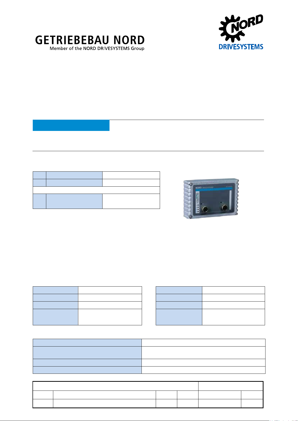
SK TU4-POL
Technical Information / Datasheet
Part number: 275 281 118
POWERLINK - External bus interface
ATTENTION
All of the information that is relevant for a safe start-up of this module and the frequency inverter is only available
under these conditions.
Validity of the documents
Scope of delivery
1 x Module SK TU4-POL
4 x Hexagon socket M4 x 40 mm
Accessories required:
1 x Bus connection unit SK TI4-TU-BUS
TI 275280000 Part No. 275 280 000)
Field of use
External technolog y unit for connecting a dece ntralised fr equency inverter (SK 180E … SK 2xxE) to a
POWERLINK field bus. The module can be fitted to or in the immediate vicinity of the frequency
inverter. It is connect ed to the inv erter via the s ystem bus, an d can comm unicate directl y with up to 4
frequency inverters. 8 digital inputs and 2 digital outputs are available.
Technical data
Module
Temperature range -25 °C … 50 °C Vibration resistance 3M7
Temperature class Class 3k3 Firmware version V1.2 R0
Protection class IP55 Hardware version AA
Supply voltage 24 V ± 20 %, ≈ 100 mA
Reverse polarity protected
* module fitted to BUS-connection unit
Digital input - working area Low: 0 V … 5 V, High: 15 V … 30 V
Digital input - specif ic dat a Ri = 8 kΩ, input capacity: 10nF, reaction time 1 ms, in puts
Digital output - 24 VDC power supply ≤ 400 mA (input)
Digital output - working area Low = 0 V, High = 24 V; max. 200 mA
Dimensions [mm]* H x W x D: 95 x 136 x 99
Depth: 108mm with covers on M12
according to EN 61131-2 type 1
-connection
POWERLINK Bus module SK TU4-POL
1.1 LED - displays, technical datas, Error 10.9 4913 Rck TI 275281118 GB
version reason for change(s) issue name document speech
Page 2
POWERLINK Bus module – SK TU4-POL
Diagnostic socket on the device (if available) or possibly
PIN
Signal
Description
1
TX+
Transmission Data +
2
RX+
Receive Data +
4
RX-
Receive Data -
Bus specification
POWERLINK Max. 100 MBaud Cable Min. Ethernet CAT-5
Electrical isolation 500 V
Max. cable length 100 m between two modules
eff
Bus connection 2 x M12 Shield via M12 direct to PE
Bus termination Takes place automatically PE connection via PE screw connection
Status display 6 LEDs in the terminal box
Topology* Star, tree, linear bus
Performance
Update interval for process data between module and frequency inverter ≈ 2.5 ms
Parameter read access on the frequency inverter ≈ 25 ms
Parameter write access with storage in EEPROM ≈ 70 ms
Cycle times
400 µs … 60 ms
Pos: 6 /Technis c h e Inf ormation en/ SK xUx - Bus - Er weiterung en/Powerli n k /M erkmale [PO L Allgemein] @ 3\ mod_1377869060850_388.docx @ 92057 @ 5 @ 1
Module features
Hot Plugging (CN connection during operation) Yes
Isochronous (PDO) Yes, Statistical Mapping
Number of process data 12 Byte (SK TU3-…),
50 Byte (SK xU4-…)
Asynchronous Data (SDO over ASND or UDP/IP) Yes
Cross Traffic No, no direct communication between CN
Addressing via DIP switch, module parameters possible
Access for NORD diagnosis tool via
via frequency inverter and UDP Ethernet protocol
Pos: 7 /Technis c h e Inf ormation en/ SK xUx - Bus - Er weiterung en/Allgem ein - System übergreif end/Montag e [SK TU4- xxx-xxx] @ 2\mod_1353315135994_388.docx @ 51251 @ 5 @ 1
Installation
The module must be attac h ed to t he s u ita ble c o nn ec tio n un it (S K TI4-TU- …) and connected using th e
four M4 x 40 mm provided hex agon socket collar s crews. Installation det ails can be found in the data
sheet for the relevant connection units.
Pos: 10 /T echnische I nformatio nen/SK xUx - Bus - Erweit erungen/Al lgemein - S ystemüberg reifend/Ans chlüsse - E thernetsei te - Variant e M12 [SK TU4-.. .EIP/ECT/ POL/Ansc hlüsse - Eth ernetseite - Variante M 12 [SK TU4-. ..EIP/ECT/POL/PN T(-M12)...- C)] @ 4\mod_1385383150995_388.docx @ 106697 @ 5 @ 1
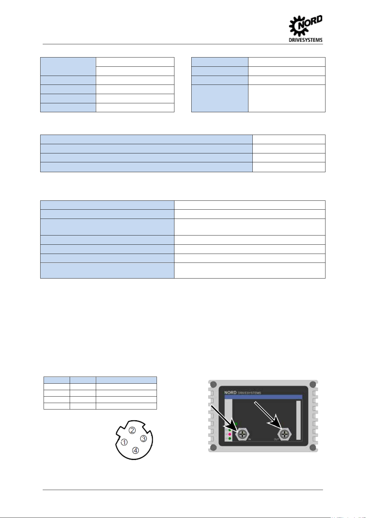
Connections
The two Ethernet lines are connected exclusively via the two M12 sockets on the front. If the module is
the final subscriber on the line, one M12 socket can remain unoccupied. The use of EMC screw
connections is recommended.
3 TX- Transmission Data -
PIN assignment
M12-4 socket
("D“- coded):
Pos: 11 /T echnische I nformatio nen/SK xUx - Bus - Erweit erungen/Al lgemein - S ystemüberg reifend/Ans chlüsse - K lemmenleis te [SK TU 4(-C) - EtherNet B aug ruppen all g e mei n] @ 3\mod_1362998963057_388.docx @ 61424 @ @ 1
2 TI 275281118 - 4913
Page 3
POWERLINK Bus module – SK TU4-POL
Potential
Contact
Designation
Description
1
24V
Supply potential (+24 V, ≤ 200 mA)
2
24V
Supply potential (+24 V, ≤ 200 mA)
3
DIN5
Digital input 5
4
DIN7
Digital input 7
5
DIN6
Digital input 6
6
DIN8
Digital input 8
7
0V
Reference potential (0 V / GND)
9
24V
Supply potential (+24 V, ≤ 200 mA)
10
24V
Supply potential (+24 V, ≤ 200 mA)
11
24V
Supply voltage (+24 V)
12
24V
Supply voltage (+24 V)
13
24V
Supply voltage (+24 V)
14
SYS +
System bus data line +
15
0V
Reference potential (0 V / GND)
16
SYS -
System bus data line -
17
0V
Reference potential (0 V / GND)
18
0V
Reference potential (0 V / GND)
19
DIN1
Digital input 1
20
DIN3
Digital input 3
21
0V
Reference potential (0 V / GND)
22
0V
Reference potential (0 V / GND)
23
24V
Supply voltage (+24 V)
24
24V
Supply voltage (+24 V)
25
DIN2
Digital input 2
26
DIN4
Digital input 4
27
0V
Reference potential (0 V / GND)
29
24V
Supply voltage (+24 V)
30
24V
Supply voltage (+24 V)
31
VI 24V2
Supply potential (+24 V - in) of the digital outputs
32
0V2
Reference potential (0 V / GND) of the digital outputs
33
DOUT1
Digital output 1 (+24 V, ≤ 200 mA)
34
DOUT2
Digital output 2 (+24 V, ≤ 200 mA)
35
0V2
Reference potential (0 V / GND) of the digital outputs
36
0V2
Reference potential (0 V / GND) of the digital outputs
RJ12 - 1
RS485_A
Data cable RS485
RJ12 - 2
RS485_B
Data cable RS485
RJ12 - 4
RS232_TxD
Data cable RS232
RJ12 - 5
RS232_RxD
Data cable RS232
RJ12 - 6
24 V
Supply voltage (+24 V)
VI 24V
GND/0V
SYS +
SYS -
24V
GND/0V
SYS +
SYS -
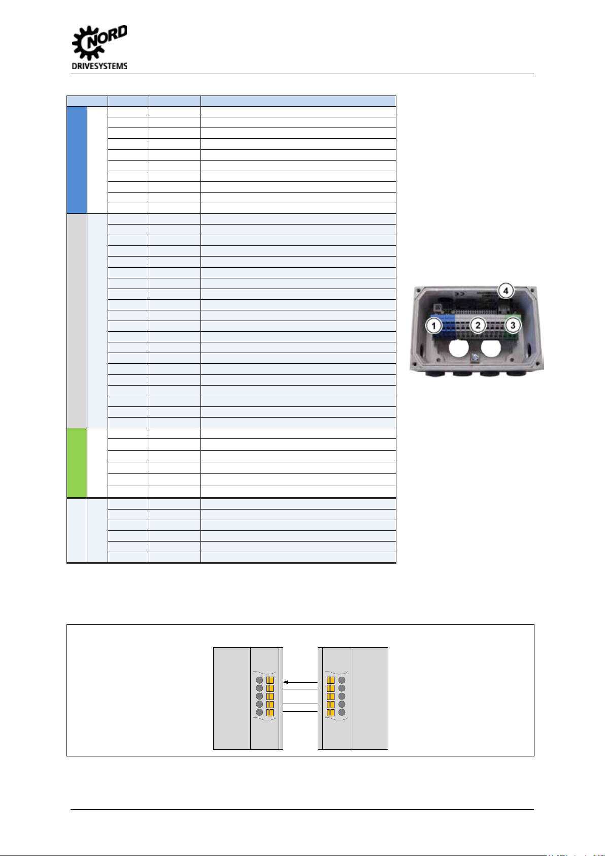
The connection to other signal and control lines takes place via the BUS - connection units.
1
Digital inputs
8 0V Reference pot en t ial (0 V / GND)
2
System bus level and digital inputs
28 0V Refere nc e pot en ti al (0 V / GND)
3
Digital outputs
4
RJ12 - 3 GND Reference potential (GND)
Diagnosis
Schematic diagram - electrical connection
(Terminal designation on example of NORD frequency inverter SK 180E … SK 2xxE)
SK TI4-TU4 BUS SK 180E … SK 2xxE
Pos: 15 /T echnische I nformatio nen/SK xUx - Bus - Erweiterungen/Power l ink/Konfiguration [SK TU4-POL(-C)] @ 3\mod_1377869058859_388.docx @ 91957 @ 5 @ 1
TI 275281118 - 4913 3
Page 4

POWERLINK Bus module – SK TU4-POL
DIP switch
Meaning
12
11
10 9 8 7 6 5 4 3 2
1
Address
X X 0 0 0 0 0 0 0 0 X
0
X X 0 0 0 0 0 0 0 1 X 1 X X 0 0 0 0 0 0 1 0 X 2 X X 0 - - - - - - - X - X X 1 1 1 0 1 1 1 1 X
239 (largest permissible address)
0 System bus terminating resistor not set
1 System bus terminating resistor set
Access rights for remote maintenance
0 Only read access to parameters possible.
1 Read and write access to param et ers possible.
0 No control possible.
1 Control is possible.
remote maintenance. The type of access is
BS
green
Module status
BE
red
Network Error
2
L/A
green
Link/Activity
1 … 12
ON OFF
Configuration
The basic configuration of the m odule is primarily carried out via its DIP - switches. The DIP - switch
settings are read after a "Power On" of the module.
No function
1. System bus (DIP 1)
The system bus mus t be terminated at both physica l
ends.
2. IP address (DIP 2 - 9)
The node ID (the final byte of the IP address) c an be
set via this switch and contr olled in parameter P185.
The largest permissible node ID for CN is 239
3. Access rights for remote maintenance (DIP 10 – 12)
With the Ethernet protocol UDP, the module and the
connected frequency inverter can be accessed via
determined via the DIP - switch with inputs 10 to 11.
Pos: 18 /T echnische I nf ormatione n/ SK xUx - Bus - Erw eiterunge n/Powerlin k/LED Anzei gen [SK TU 4-POL(-C)] @ 3\mod_1377869059920_388.docx @ 92007 @ 5 @ 1
LED displays
The operating statuses of the module are visualised using LED indicators.
No. Name Colour Meaning
1
DS green Device status
DE red Device error
Pos: 20 /T echnische I nformatio nen/SK xUx - Bus - Erweiterungen/Powerlink/LED Anzeigen- POWERLINK spezifische LED [POL Allgemein] @ 3\mod_1377869060362_388.docx @ 92032 @ @ 1
4 TI 275281118 - 4913
Page 5

BS
(Module status)
Meaning
OFF
No communication
Flashing gree n 1x
Pre Operational 1: Parameter communication active, no process data
Flashing gree n 3x
Ready To Operate: Param ete r c om m unication active, restrict ed pr oces s data com m uni cation
Green ON
Operational: Parameter communication active, process data communication active
Flashing gree n (10 Hz)
Basic Ethernet: P a ram et er com m uni c at i on activ e via UDP , no pro ces s data
Flashing gree n (2.5 Hz)
Stopped: No communication
BE
(Network Error)
Meaning
OFF
No POWERLINK error
Red ON
General POWERLINK error
OFF
• Module not ready, no control voltage.
• No bus connection (check cable connection)
Flashing gree n
• Technology box connected and active
Green ON
• no bus activity available
Meaning
Short flash = 0.25 s on / 1 s off
OFF
OFF
Module not ready, no control voltage.
ON
OFF
Module ready, no error, at least one frequency inverter is communicating via the system bus
ON
Short flashing
Module ready, but
• One or more of the connected frequency inverters has fault status
Long flashing
OFF
Module ready and at least one other participant is connected to the system bus, but
Long flashing
Short flashing
• Frequency inverter has no supply voltage
Long flashing
Short flashing
System bus is in status "Bus Off"
Long flashing
Short flashing
System bus is in status "Bus Off"
Long flashing
Short flashing
4 x - 1s pause
OFF
Short flashing
System error, internal program sequence interrupted
• Module defective
POWERLINK-specific LEDs
POWERLINK Bus module – SK TU4-POL
Flashing gree n 2x
L/A
(Green LED)
Pre Operational 2: as for Pre Operational 1
Meaning
Technology unit read y, but
Pos: 21 /T echnische I nformatio nen/SK xUx - Bus - Erweit erungen/All gemein - S ystemüberg reifend/LED Anzeigen- N ORD spezifische LED [EIP / POL / ECT / PNT Allgemein] @ 3\mod_1363773424248_388.docx @ 61815 @ @ 1
NORD-specific LEDs
DS
(Device status)
DE
(Device error)
Long flash = 0.5 s on / 1 s off
Flash interval
1 x - 1s pause
Flash interval
2 x - 1s pause
Flash interval
3 x - 1s pause
Flash interval
Flash interval
1…7 - 1s pause
Pos: 22 /T echnische I nformatio nen/SK xUx - Bus - Erweit erungen/All gemein - S yst e mübergreif e n d/ F ehlermeldu ngen Ether ne t B a ug r u pp en allgemein [SK xUx-EIP / POL - Al l g e mein] @ 3\mod_1363779786491_388.d ocx @ 61865 @ 5 @ 1
• no frequency inverter connected to system bus (connection may be interrupted)
•
one or more system bus clients has address error
• Software incompatible (module software and FI software do not match - update required)
System bus is in status "Bus Warning"
• Communication on system bus disrupted
•
No other clients available on system bus
•
Module not inserted correctly or no connection to the system bus
• the system bus 24V power supply was interrupted during operation
• No system bus 24V power supply
Module error
•
see parameter P170
• EMC interference (observe wiring guidelines!)
TI 275281118 - 4913 5
Page 6

POWERLINK Bus module – SK TU4-POL
Error
Meaning
Remarks
100.0
EEPROM error
EMC fault, module defective
102.0
Timeout
via P151/P513 monitoring
103.0
System bus BUS OFF
No 24V supply to the bus, connections not correct
104.0
Module temperature > 97°C
SK CU4-… only, zpermissiv e internal temperature of the mo dule
550.1
DIP switch error
The DIP switches (IP address) could not be read correctly
560.0 …
560.9
Internal error
Module not r eady
561.0
General network error
561.1
Ethernet Watchdog timeout
561.3
IP address error
IP address of the module has been doubly assigned
563.0
Firmware version incompatible
The firmware version cannot be used for the device
564.0
MAC address error
Error
(E010)
Meaning
Remarks
10.1
ASIC errors
Communication to Ethernet - ASIC lost
• Switch-off of the supply voltage
10.2
Ethernet/IP Watchdog timeout
Telegram transfer error
• Check the Watchdog time
10.4
IP address error
IP address of the module has been doubly assigned
10.6
Bus cable fault
Bus cable connection interrupted
10.8
The connection between the inverter
Only SK TU3 module
10.9
Module missing (P120)
Only SK xU4 module
Error messages
Error messages fr om the m odule - present error s or archived m es sages relating t o the last err or - can
be read out via the module par ameter (P170). The error messages are lost if the m odule is switched
off.
exceeded for approx. 60 sec.
561.2 Bus cable fault Bus cable connection interrupted
Errors which occur in relation to the module are depicted as follows in the error memory of the
frequency inverter (P700 / P701).
10.0 Connection error Contact to SK xU4 lost
10.3 Timeout by P151/P513 Telegram transfer error
10.5 Internal error Module not ready,
and the module had a timeout
Pos: 23 /T echnische I nformatio nen/SK xUx - Bus - Erweit erungen/Al lgemein - Systemübergreifend/Parameter [SK xUx-... Allgemein - Freq uenzumric hter] @ 4\ mod_1384953855694_388.docx @ 105781 @ 5 @ 1
• Check the connections and links, pro gr am sequence and
Bus Master
•
Check the connections and links
• for SK CU4-… e.g.: Module temperature > 97°C
6 TI 275281118 - 4913
Page 7

P120 [-01]
Option monitoring
"Auto“ (default setting)
Only SK xU4
P509
Control word source
SK TU3-… on SK 5xxE: "Ethernet TU”
"System bus"
"Auto“ (default setting)
and P543 … P545
P546 [-01 …-03 (-05)]
and P546 … P548
Bus target values (1 …3 (… 5))
Possible settings according to (P400)
P740 / P741
Process data bus In / Out
Information parameters
P745
Module version
Information parameters
Only SK TU3
P745
Module status
Information parameters
Only SK TU3
P748
CANopen / System bus status
Information parameters
Parameter [-Array]
Meaning
Remarks
-TU3-
-TU4-
-CU4-
P150
Set relays
Set DOUT directly or control via BUS
X
P151
External bus time-out
Monitoring of SK xU4 bus module
X X
P152
Factory setting
Reset module parameters
X X X
P153 [-01 …-02]
Minimum system bus cycle
Reduction of the b us load on the s ystem bus cause d
X X
module
P160
Node ID/IP address 4
The value from the DIP-switch has priority
X X X
P162 [-01 …-32]
Device name
Name of the module in the POWERLINK network
X X X
P164 [-01 …-04]
IP Gateway
Default setting: -01 … -04 : 192 / 168 / 100 / 254
X X X
P165
POWERLINK cycle
For synchronisation with Manage Node
X X X
P170 [-01 … -02]
Present errors
Displaying module errors
X X X
P171 [-01 … -03]
Software version
Firmware version / Revision
X X X
P172
Configuration
Module type
X X X
P173
Module status
Status of system bus or connected FI
X X X
P175
State of relays
Image of the switching status of DOUT
X
P176 [-01 … ]
Process data bus In
Information parameters
X X X
P177 [-01 … ]
Process data bus Out
Information parameters
X X X
P178
Internal temperature
Information parameters
X
P181 [-01 … -06]
MAC address
Information parameters
X X X
P182
NMT State
Information parameter (CN status)
X X X
P183
NMT Error
Information parameter (CN error)
X X X
P184 [-01 … -06]
NMT State-change count
Information parameter (cause of change of status)
X X X
P185 [-01 …-04]
Current IP address
Information parameters
X X X
P186 [-01 …-04]
Present IP subnet mask
Information parameters
X X X
Parameters
Frequency inverter: The following frequency inverter parameters must be adapted for setting up
communication between the frequency inverter and the bus module (for details see frequency
converter manual).
Parameter [-Array] Meaning Remarks
POWERLINK Bus module – SK TU4-POL
SK xU4-… on SK 180/SK 2xxE:
P510 [-01 … -02] Setpoint source
P513 Time-out Monitoring of the SK TU3 bus module Only SK 5xxE
P543 [-01 …-03 (-05)]
P700 [-01] / P701 Current / last failures Information parameters
Pos: 24 /T echnische I nformatio nen/SK xUx - Bus - Erweit er u ng e n/Powerli n k /P ar a meter [POL Al l g e mei n] @ 3\mod_1377869061310_388.docx @ 92082 @ @ 1
Bus actual values (1 …3 (… 5)) Possible settings according to (P418)
BUS module: The module provides a selection of appropriate parameters for setting or displaying
special operating values. Parameters can be adapted using the NORDCON software or an
SK PAR-3H / -3E param eter box. All parameters can still be read an d written by the bus master via
POWERLINK.
by the module
P154 [-01 …-02] Access to option card I/O Administration of read and write rig hts to th e IO of t he
Alternative to setti ng the arra y valu e [-04]: D IP-switch,
à
X X
P163 FI sets bus error "1"= Error message in case of fault, "0" = Status
message
P174 Status of digital inputs Image of the switching status of DIN X X
X X X
Pos: 25 /T echnische I nformatio nen/SK xUx - Bus - Erweit erungen/Al lgemein - S ystemüberg reifend/Par ameterzug riff und Di agnose [Bus BG - Allg e mei n] @ 3\mod_1363794074590_388.docx @ 61915 @ 5 @ 1
TI 275281118 - 4913 7
Page 8

POWERLINK Bus module – SK TU4-POL
Access via RJ12-SK 5xxE
Access via RJ12-Bus diagnosis
connection unit
Access via RJ12-Frequency
verter diagnosis socket , if
connected to module via system
Software
Name
Software
Meaning
XDD file
Device file (characteristics and parameters)
NORD CON
Parameterisation and diagnostic software
Document
Name
Document
Meaning
BU 0000
Description of NORD CON software
BU 0200
SK 2xxE frequency inverter manual
BU 0040
ParameterBox manual
BU 2200
Description of POWERLINK bus communication
BU 0180
Frequency inverter manual SK 180E, SK 190E
TI 275280000
Bus connection unit SK TI4-TU-BUS
Parameter access and diagnosis
The NORD CON software and optional control units s uch as the SK PAR-3H pa rameter box provide
convenient access to the parameters of the module and allow status information to be read out.
SK TU3- SK TU4- SK CU4- / SK TU4-
diagnosis socket
socket SK TI4-TU-BUS(-C)
Pos: 27 /T echnische I nformatio nen/SK xUx - Bus - Erweit erungen/Po werlink/W eiterführen de Dokumentationen und Software [SK TU4-POL] @ 3\mod_1377869063745_388.docx @ 92207 @ 5 @ 1
Further Documentation and Software (www.nord.com)
=== Ende der Liste für Textmar ke Inhalt ===
in
bus.
8 TI 275281118 - 4913
 Loading...