

NORD TI 275281117 User Manual

This document is only valid in combination with the operating instructions for the relevant frequency inverter. All
Pos: 3 /Technis c h e Inf ormation en/ SK xUx - Bus - Er weiterung en/EtherC at/SK TU4-EC T / 27528 1117 / Basis informati onen [SK T U4-ECT] @ 3\ mod_1371720845716_388.docx @ 78986 @ 555 @ 1
SK TU4-ECT
Technical Information / Datasheet
Part number: 275 281 117
EtherCAT® - External bus interface
NOTICE
of the information that is relevant for a safe start-up of this module and the frequency inverter is only available
under these conditions.
Validity of the documents
Scope of supply
1 x Module SK TU4-ECT
4 x Hexagon socket M4 x 40 mm
Accessories required:
1 x Bus connection unit SK TI4-TU-BUS
TI 275280000 Part No. 275 280 000)
Field of use
External technolog y unit for connectin g a decentralised frequency inverter (SK 180E … SK 2xxE) to
an EtherCAT field bus. The module can be fitted to or in the immediate vicinity of the frequency
inverter. It is connect ed to the inv erter via the s ystem bus, and can com municate direct ly with up to 4
frequency inverters. 8 digital inputs and 2 digital outputs are available.
Technical Data
Module
Temperature range -25 °C … 50 °C Vibration resistance 3M7
Temperature class Class 3k3 Firmware version V1.6 R1
Protection class IP55 Hardware version BB
Supply voltage 24 V ± 20 %, ≈ 100 mA
Reverse polarity protected
* module fitted to BUS-connection unit
Dimensions [mm]* H x W x D: 95 x 136 x 99
Depth: 108mm with covers on M12
-connection
EtherCAT Bus module SK TU4-ECT
1.1 LED - displays, technical datas, Error 10.9 4913 Rck TI 275281117 GB
version reason for change(s) issue name document speech

EtherCAT Bus module – SK TU4-ECT
diagnosis socket on the device (if available) or via the
Digital input - working area Low: 0 V … 5 V, High: 15 V … 30 V
Digital input - specif ic dat a Ri = 8 kΩ, input capacity: 10nF, reaction time 1 ms, in puts
according to EN 61131-2 type 1
Digital output - 24 VDC power supply ≤ 400 mA (input)
Digital output - working range Low = 0 V, High = 24 V; max. 200 mA
Bus specification
EtherCAT Max. 100 MBaud Cable Min. Ethernet CAT-5
Electrical isolation 500 V
Max. cable length 100 m between two
eff
modules
Bus connection 2 x M12 Shield via M12 direct to PE
Bus termination performed automatically PE connection via PE screw connection
Status display 6 LEDs in the terminal box
Topology Linear bus
Process data 8 Byte per FI + 2 Byte for
IOs.
Total length 2 … 34 Byte
Performance
Update interval of process data for 1000 devices ≈ 1 ms
Update interval for process data between module and frequency inverter ≈ 1.5 ms
Parameter read access on the frequency inverter ≈ 12 ms
Parameter write access with storage in EEPROM ≈ 25 ms
Pos: 6 /Tec hnische Inf or mationen/ S K xUx - Bus - Er weiterungen/ EtherCat /Merkmale [ECT Allge mein] @ 3\ mod_1371724052210_388.docx @ 79062 @ 5 @ 1
Module features
Parameterisation Via CoE (CANopen over EtherCat)
Error messages (Emergency Messages) According to CANopen DS301
EtherCAT addressing (Second Address) DIP switch or module parameter
Distributed Clocks Not supported
Access for NORD diagnosis tool via
frequency inverter
Pos: 9 /Technis c h e Inf ormation en/ SK xUx - Bus - Er weiterung en/Allgem ein - System übergreif end/Montag e [SK TU4- xxx-xxx] @ 2\mod_1353315135994_388.docx @ 51251 @ 5 @ 1
Installation
The module must be attac h ed to t he s u ita ble c o nn ec tio n un it (S K TI4-TU- …) and connected using th e
four M4 x 40 mm provided hexagon socket collar s crews. Installation det ails can be found in the data
sheet for the relevant connection units.
Pos: 12 /T echnische I nformatio nen/SK xUx - Bus - Erweit erungen/Al lgemein - S ystemüberg reifend/Ans chlüsse - E thernetsei te - Variant e M12 [SK TU 4-...EIP/ ECT/POL/A nschlüsse - E thernetsei te - Variant e M12 [SK TU4-...EIP/ECT /POL/PNT(-M12) ...-C)] @ 4\mod_1385383150995_388.docx @ 106697 @ 5 @ 1
2 TI 275281117 - 4913
PIN
Signal
Description
1
TX+
Transmission Data +
2
RX+
Receive Data +
3
TX-
Transmission Data -
4
RX-
Receive Data -
Potential
Contact
Designation
Description
1
24V
Supply potential (+24 V, ≤ 200 mA)
2
24V
Supply potential (+24 V, ≤ 200 mA)
3
DIN5
Digital input 5
4
DIN7
Digital input 7
5
DIN6
Digital input 6
6
DIN8
Digital input 8
7
0V
Reference potential (0 V / GND)
8
0V
Reference potent ial (0 V / GND)
9
24V
Supply potential (+24 V, ≤ 200 mA)
10
24V
Supply potential (+24 V, ≤ 200 mA)
11
24V
Supply voltage (+24 V)
12
24V
Supply voltage (+24 V)
13
24V
Supply voltage (+24 V)
14
SYS +
System bus data line +
15
0V
Reference potential (0 V / GND)
16
SYS -
System bus data line -
18
0V
Reference potential (0 V / GND)
19
DIN1
Digital input 1
20
DIN3
Digital input 3
21
0V
Reference potential (0 V / GND)
22
0V
Reference potential (0 V / GND)
23
24V
Supply voltage (+24 V)
24
24V
Supply voltage (+24 V)
25
DIN2
Digital input 2
26
DIN4
Digital input 4
27
0V
Reference potential (0 V / GND)
28
0V
Reference potent ial (0 V / GND)
29
24V
Supply voltage (+24 V)
30
24V
Supply voltage (+24 V)
31
VI 24V2
Supply potential (+24 V - in) of the digital outputs
32
0V2
Reference potential (0 V / GND) of the digital outputs
33
DOUT1
Digital output 1 (+24 V, ≤ 200 mA)
34
DOUT2
Digital output 2 (+24 V, ≤ 200 mA)
35
0V2
Reference potential (0 V / GND) of the digital outputs
36
0V2
Reference potential (0 V / GND) of the digital outputs
RJ12 - 1
RS485_A
Data cable RS485
RJ12 - 2
RS485_B
Data cable RS485
RJ12 - 3
GND
Reference potential (G ND )
RJ12 - 4
RS232_TxD
Data cable RS232
RJ12 - 5
RS232_RxD
Data cable RS232
RJ12 - 6
24 V
Supply voltage (+24 V)
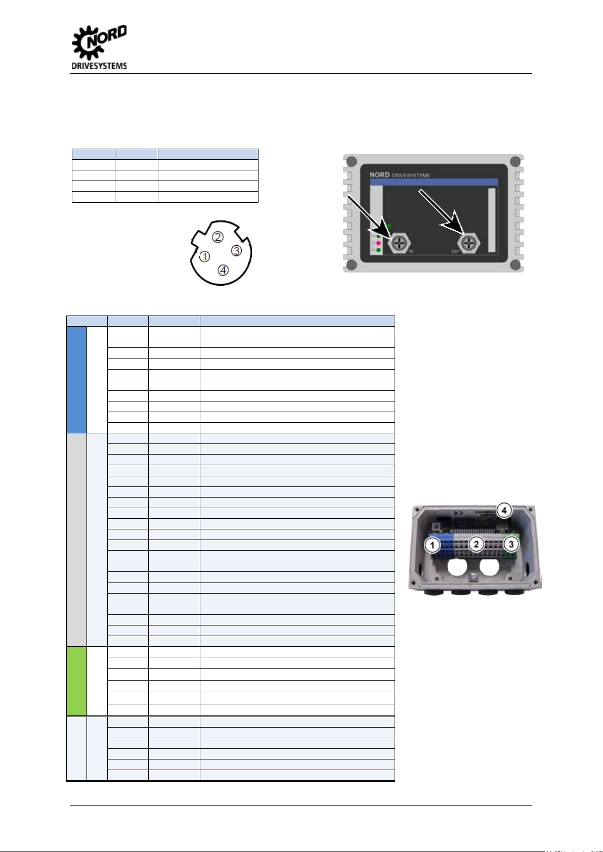
Connections
The two Ethernet lines are connected exclusively via the two M12 sockets on the front. If the module is
the final subscriber on the line, one M12 socket can remain unoccupied. The use of EMC screw
connections is recommended.
EtherCAT Bus module – SK TU4-ECT
PIN assignment
M12-4 socket
("D“- coded):
Pos: 13 /T echnische I nformatio nen/SK xUx - Bus - Erweit erungen/Al lgemein - S ystemüberg reifend/Ans chlüsse [TU 4(-C) - EtherNet Baugruppen allgem ein (SK TU4-EIP(-C) /Anschlüsse - Kle mmenleiste [ SK TU4(-C) - Et herNet Baugr u ppen allge mei n] @ 3\mod_1362998963057_388.docx @ 61424 @ @ 1
The connection to other signal and control lines takes place via the BUS - connection units.
1
Digital inputs
17 0V Refere nc e pot en ti al (0 V / GND)
2
System bus level and digital inputs
3
Digital outputs
4
Diagnosis
TI 275281117 - 4913 3
 Loading...