

Page 1
combination with the operating instructions for the relevant frequency inverter. All
Pos: 3 /Technis c h e Inf ormation en/ SK xUx - Bus - Er weiterung en/PROFIN ET IO/SK TU4- PNT / 275281115 / Basi sinformationen [SK TU4-PNT] @ 4\mod_1385371089311_388.docx @ 106401 @ 555 @ 1
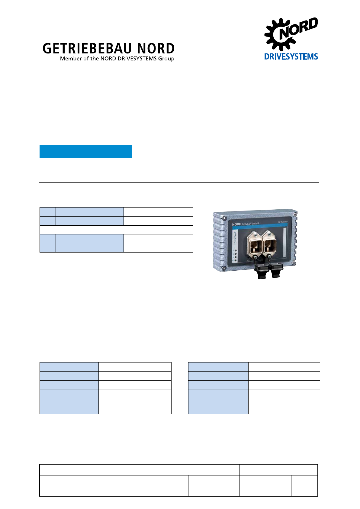
SK TU4-PNT
Technical Information / Datasheet
Part number: 275 281 115
PROFINET IO® - External Bus – Interface
NOTICE
This document is only valid in
of the information that is relevant for a safe start-up of this module and the frequency inverter is only available
under these conditions.
Validity of this document
Scope of delivery
1 x Module SK TU4-PNT
4 x Hexagon socket M4 x 40 mm
Accessories required:
1 x Bus connection unit SK TI4-TU-BUS
TI 275280000 (Part No. 275 280 000)
Field of use
External technolog y unit for c onnecti on of a dec entral ised f requency inverter (SK 1 80E … S K 2xxE) to
a PROFINET IO field bus. The module can be mounted on, or in the immediate vicinity of the
frequency inverter. I t is connected to the inverter via the system bus, and can comm unicate directly
with up to 4 frequency inverters. 8 digital inputs and 2 digital outputs are available.
Technical data
Module
Temperature range -25 °C … 50 °C Vibration resistance 3M7
Temperature class Class 3K3 Firmware version V1.2 R0
Protection class IP55 Hardware version AA
Supply voltage 24 V ± 20 %, ≈ 100 mA
Dimensions [mm]* H x W x D: 95 x 136 x 109
Reverse polarity
protected
* module fitted to BUS-connection unit
Depth: 154 mm with cover caps on the RJ45
-connection
PROFINET IO Bus module SK TU4-PNT
1.0 Erstausgabe / first issue 4913 Rck TI 275281115 GB
version reason for change(s) issue name document speech
Page 2
PROFINET IO Bus module – SK TU4-PNT
Isochronous real time communication of synchronised
Transmission and receiver cables are automatically
diagnosis socket on the device (if available) and possibly
Digital input - working range Low: 0 V … 5 V, High: 15 V … 30 V
Digital input - specif ic dat a Ri = 8 kΩ, input capacity: 10 nF, response time 3 ms,
inputs as per EN 61131-2 type 1
Digital output - 24 VDC power supply ≤ 400 mA (input)
Digital output - working range Low = 0 V, High = 24 V; max. 200 mA
Bus specification
EtherNet/IP Max. 100 MBaud Cable Min. Ethernet CAT-5
Electrical isolation 500 V
Max. cable length 100 m between two
eff
modules
Bus connection 2 x RJ45 Shield Via RJ45 directly to PE
Bus termination performed automatically PE connection via PE screw connection
Status display 8 LEDs in the terminal box
Topology Star, tree, ring, linear bus
Performance
Update interval for process data between module and frequency inverter ≤ 5 ms
Parameter read access on the frequency inverter ≈ 15 ms
Parameter write access with storage in EEPROM ≈ 25 ms
Cycle times ≥ 1 ms
Pos: 8 /Technis c h e Inf ormation en/ SK xUx - Bus - Er weiterung en/PROFIN ET IO/Mer kmale [PNT Allgemein] @ 4\ mod_1385365458675_388.docx @ 106301 @ 5 @ 1
Module features
Communication RT (Real Time)
à Real time communication of process data
IRT (Isochronous Real Time)
à
process data
Addressing Automatic address assignment via IO controller using DCP
(Discovery Configuration Protocol)
Data transfer via Switched Ethernet
Autonegotiation Negotiation of transfer parameters
Autocrossover
crossed in the switch as necessary
Conformity classes CC-B, and CC-C
Access for NORD diagnosis tool via
via frequency inverter and
Ethernet protocols UDP or TCP/IP
Pos: 11 /T echnische I nformatio nen/SK xU x - Bus - Erwei terungen/ Allgemein - Systemübergreifend/Montage [SK TU4-xxx-xxx] @ 2\mod_1353315135994_3 88.docx @ 51251 @ 5 @ 1
Installation
The module must be attac h ed to t he s u ita ble c o nn ec tio n un it (S K TI4-TU- …) and connected using th e
four M4 x 40 mm provided hexagon s ocket collar sc rews. Installation det ails can be found in the data
sheet for the relevant connection units.
Pos: 15 /T echnische I nformatio nen/SK xUx - Bus - Erweit erungen/PR OFINET IO /Anschlüss e [SK TU4-PN T(-C) - PROFINET I O Baugruppen mit RJ45 (SK TU4-PNT(-C)] @ 4\mod_1385379540114_388.docx @ 106672 @ 5 @ 1
2 / 8 TI 275281115 - 4913
Page 3
PROFINET IO Bus module – SK TU4-PNT
RJ45 PIN
Signal
Description
1
TX+
Transmission Data +
2
TX-
Transmission Data -
3
RX-
Receive Data +
6
RX-
Receive Data -
Potential
Contact
Designation
Description
1
24V
Supply potential (+24 V, ≤ 200 mA)
2
24V
Supply potential (+24 V, ≤ 200 mA)
3
DIN5
Digital input 5
4
DIN7
Digital input 7
5
DIN6
Digital input 6
7
0V
Reference potential (0 V / GND)
8
0V
Reference potent ial (0 V / GND)
9
24V
Supply potential (+24 V, ≤ 200 mA)
10
24V
Supply potential (+24 V, ≤ 200 mA)
11
24V
Supply voltage (+24 V)
12
24V
Supply voltage (+24 V)
13
24V
Supply voltage (+24 V)
14
SYS +
System bus data line +
15
0V
Reference potential (0 V / GND)
16
SYS -
System bus data line -
17
0V
Reference potential (0 V / GND)
18
0V
Reference potential (0 V / GND)
19
DIN1
Digital input 1
20
DIN3
Digital input 3
21
0V
Reference potential (0 V / GND)
22
0V
Reference potential (0 V / GND)
23
24V
Supply voltage (+24 V)
24
24V
Supply voltage (+24 V)
25
DIN2
Digital input 2
26
DIN4
Digital input 4
27
0V
Reference potential (0 V / GND)
28
0V
Reference potent ial (0 V / GND)
29
24V
Supply voltage (+24 V)
30
24V
Supply voltage (+24 V)
31
VI 24V2
Supply potential (+24 V - in) of the digital outputs
32
0V2
Reference potential (0 V / GND) of the digital outputs
33
DOUT1
Digital output 1 (+24 V, ≤ 200 mA)
34
DOUT2
Digital output 2 (+24 V, ≤ 200 mA)
36
0V2
Reference potential (0 V / GND) of the digital outputs
RJ12 - 1
RS485_A
Data cable RS485
RJ12 - 2
RS485_B
Data cable RS485
RJ12 - 3
GND
Reference potential (G ND )
RJ12 - 4
RS232_TxD
Data cable RS232
RJ12 - 5
RS232_RxD
Data cable RS232
RJ12 - 6
24 V
Supply voltage (+24 V)
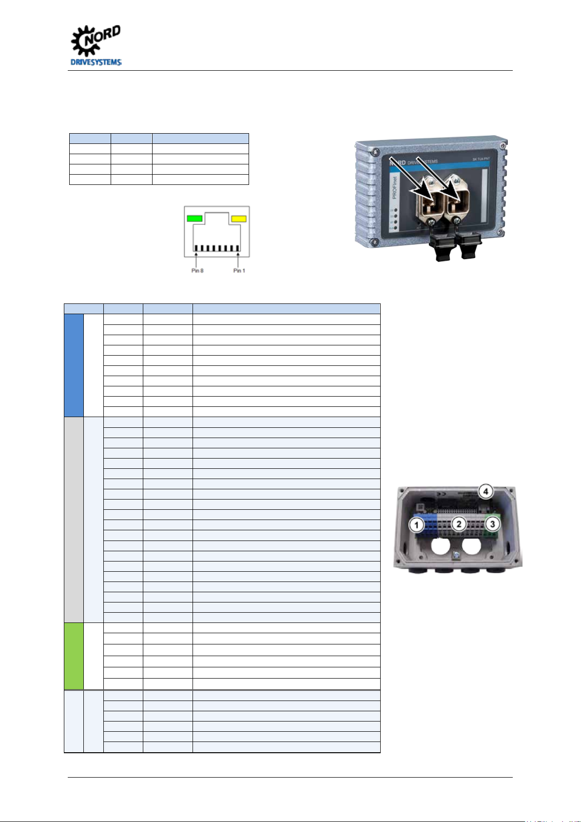
Connections
The two Ethernet l ines are connected ex clusiv ely via t he two RJ4 5 sock ets on th e front. If the m odule
is the final participant on the line, one RJ45 socket can remain unoccupied.
PIN connections
RJ45 socket:
Pos: 16 /T echnische I nformatio nen/SK xUx - Bus - Erweit erungen/Al lgemein - S ystemüberg reifend/Ans chlüsse - K lemmenleis te [SK TU 4(-C) - EtherNet B aug ruppen all g e mei n] @ 3\mod_1362998963057_388.docx @ 61424 @ @ 1
The connection to other signal and control lines takes place via the BUS - connection units.
1
2
6 DIN8 Digital input 8
Digital inputs
System bus level and digital inputs
3
35 0V2 Reference potential (0 V / GND) of the digital outputs
Digital outputs
4
Diagnosis
TI 275281115 - 4913 3 / 8
Page 4

PROFINET IO Bus module – SK TU4-PNT
VI 24V
GND/0V
SYS +
SYS -
24V
GND/0V
SYS +
SYS -
DIP switch
Meaning
12
11
10 9 8 7 6 5 4 3 2
1
X X
X
No function
X
0 System bus terminating resistor not set
1 System bus terminating resistor set
Access rights for remote maintenance
0 Only read access to parameters possible.
0 No control possible.
1 Control is possible.
0 TCP/IP open connection.
1 Secure TCP/IP connection.
can be
No.
Name
Colour
Meaning
DS
green
Device status
DE
red
Device error
1 … 12
ON
OFF
Schematic diagram - electrical connection
(Terminal designation on example of NORD frequency inverter SK 180E … SK 2xxE)
SK TI4-TU4 BUS SK 180E … SK 2xxE
Pos: 19 /T echnische I nformatio nen/SK xUx - Bus - Erweit erungen/PR OFINET IO /Konfigura tion [SK TU 4-PNT(-C(-M12))] @ 4\mod_1385046026847_388 .docx @ 106049 @ 5 @ 1
Configuration
Configuration of the m odule for remote m aintenance or for the system bus is carried out via th e DIP
switches. The DIP - switch settings are read after a "Power On" of the module.
1 Read and write access to parameters p os sible.
1. System bus (DIP 1)
The system bus must be terminated at both physical
ends.
2. (DIP 2 - 9)
No function
3. Access rights for remote maintenance (DIP 10 – 12)
Via the Ethernet pr otocols T CP and UDP th e m odule
and the connected frequency inverter
accessed using remote maintenance. The type of
access is determ ined via the DIP - switch with input s
10 to 12.
Pos: 22 /T echnische I nf ormatione n/ SK xUx - Bus - Erweiterungen/PROFINET IO/LED Anzeigen [SK TU4-PNT(-C)] @ 4\mod_1385046540805_388.docx @ 106124 @ 5 @ 1
LED displays
The operating statuses of the module are visualised using LED indicators.
RUN green Ethernet State
BF red Ethernet Error
1
Link green Link
2
4 / 8 TI 275281115 - 4913
Act yellow Activity
Page 5

PROFINET IO Bus module – SK TU4-PNT
OFF
Initialisation
OFF
Flashing gree n
No connection to PROFINET IO controller
No process data communication
Flashing red
No process data communication
Process data communication active
Double-flashing
1sec pause)
PROFINET or FI timeout,
OFF
OFF
• Module not ready, no control voltage.
• No bus connection (check cable connection)
ON
OFF
• Bus connection (cable connection) to another Ethernet device exists
ON
Flashing
• Bus activity present
Meaning
Short flash = 0.25 s on / 1 s off
OFF
OFF
Module not ready, no control voltage.
ON
OFF
Module ready, no error, at least one frequency inverter is communicating via the system bus
ON
Short flashing
Module ready, but
• One or more of the connected frequency inverters has fault status
Long flashing
Short flashing
• Frequency inverter has no supply voltage
Long flashing
Short flashing
System bus is in status "Bus Off"
Long flashing
Short flashing
System bus is in status "Bus Off"
Long flashing
Short flashing
4 x - 1s pause
OFF
Short flashing
System error, internal program sequence interrupted
• Module defective
Pos: 24 /T echnische I nformatio nen/SK xUx - Bus - Erweiterungen/PROFIN ET IO/LED Anzeigen- PROFINET spezifische LED [PNT Allgemein] @ 4\mod_ 1385130089638_388.docx @ 106275 @ @ 1
PROFINET-specific LED
RUN
(Ethernet State)
Meaning BF
No operating voltage
(Ethernet Error)
Meaning
No error
No parameter communication
Green ON
Parameter communication active
Link
(Green LED)
Activity
(Yellow LED)
(Blinking)
Pos: 25 /T echnische I nformatio nen/SK xUx - Bus - Erweit erungen/Al lgemein - S ystemüberg reifend/LED Anzeigen- N ORD spezifische LED [EIP / POL / ECT / PNT Allge mei n] @ 3\mod_1363773424248_388.docx @ 61815 @ @ 1
NORD-specific LEDs
DS
(Device status)
Long flashing OFF
DE
(Device error)
Flash interval
1 x - 1s pause
à e.g. wrong GSDML file
Red ON
Ethernet error à there is no physical
connection to a further participant
red
(see also P151, P513)
(2 x 0.25 s,+
Meaning
• No bus activity
• Bus connection (cable connection) to another Ethernet device exists
Long flash = 0.5 s on / 1 s off
Module ready and at least one oth er pa rti ci p ant is connected to the system bus, but
•
no frequency inverter connected to system bus (connection may be interrupted)
•
one or more system bus clients has address error
• Software incompatible (module software and FI software do not match - update required)
System bus is in status "Bus Warning"
• Communication on system bus disrupted
•
No other clients available on system bus
•
Module not inserted correctly or no connection to the system bus
Flash interval
• the system bus 24V power supply was interrupted during operation
2 x - 1s pause
Flash interval
3 x - 1s pause
• No system bus 24V power supply
Module error
Flash interval
Flash interval
1…7 - 1s pause
•
see parameter P170
• EMC interference (observe wiring guidelines!)
Pos: 26 /T echnische I nformatio nen/SK xUx - Bus - Erweiterungen/PROFIN ET IO/Fehlermeldun gen Profinet Baugruppen allgemein [SK xUx -PNT - Allgemein] @ 4\mod_1384961728468_388.docx @ 105889 @ 5 @ 1
TI 275281115 - 4913 5 / 8
Page 6

PROFINET IO Bus module – SK TU4-PNT
Error
Meaning
Remarks
100.0
EEPROM error
EMC fault, module defective
102.0
Timeout
via P151/P513 monitoring
104.0
Module temperature too high
only SK CU4-…, permissible internal temperature of the bus
module exceeded for approx. 60 sec
560.0 …
Internal error
Module not r eady
561.0
General network error
561.1
Ethernet Watchdog timeout
561.2
Bus cable fault
Bus cable connection interrupted
561.3
IP address error
IP address of the module has been doubly assigned
563.0
Firmware version incompatible
The firmware version cannot be used for the device
564.0
MAC address error
Error
(E010)
Meaning
Remarks
10.0
Connection error
Contact to SK xU4 lost
10.1
ASIC errors
Communication to Ethernet - ASIC lost
• Reduce the temperature of the module (only SK CU4-…)
• Check the Watchdog time
10.4
IP address error
IP address of the module has been doubly assigned
10.5
Internal error
Module not ready for operation, configuration error
10.6
Bus cable fault
Bus cable connection interrupted
and the module had a timeout
10.9
Module missing (P120)
Only SK xU4 module
Error messages
Error messages fr om the m odule - present error s or archived m ess ages relating t o the last error - can
be read out via the module par ameter (P170). The error messages are lost if the m odule is switched
off.
103.0 System bus BUS OFF No 24V supply to the bus, connections not correct
560.9
Errors which occur in relation to the module are depicted as follows in the error memory of the
frequency inverter (P700 / P701).
10.2 Ethernet Watchdog timeout Telegram transfer error
10.3 Timeout by P151/P513 Telegram transfer error
10.8 The connection between the inverter
Pos: 27 /T echnische I nformatio nen/SK xUx - Bus - Erweit erungen/Al lgemein - Systemübergreifend/Parameter [SK xUx-... Allgemein - Freq uenzumric hter] @ 4\mod_1384953855694_388.docx @ 105781 @ 5 @ 1
• Switch-off of the supply voltage
• Check the connections and links, program sequence and
Bus Master
• Check the connections and links
Only SK TU3 module
6 / 8 TI 275281115 - 4913
Page 7

PROFINET IO Bus module – SK TU4-PNT
Parameter [-Array]
Meaning
Remarks
P120 [-01]
Option monitoring
"Auto“ (default setting)
Only SK xU4
P509
Control word source
SK TU3-… on SK 5xxE: "Ethernet TU”
SK xU4-… on SK 180/SK 2xxE: "System bus"
P510 [-01 … -02]
Setpoint source
"Auto“ (default setting)
P513
Time-out
Monitoring of the SK TU3 bus module
Only SK 5xxE
P543 [-01 …-03 (-05)]
Bus actual values (1 …3 (… 5))
Possible settings according to (P418)
and P546 … P548
P700 [-01] / P701
Current / last failures
Information parameters
P740 / P741
Process data bus In / Out
Information parameters
P745
Module version
Information parameters
Only SK TU3
P745
Module status
Information parameters
Only SK TU3
P748
CANopen / System bus status
Information parameters
Parameter [-Array]
Meaning
Remarks
-TU3-
-TU4-
-CU4-
P150
Set relays
Set DOUT directly or control via BUS
X
P151
External bus time-out
Monitoring of the SK xU4 bus module
X X
P152
Factory setting
Reset module parameters
X X X
P153 [-01 …-02]
Minimum system bus
cycle
Reduction of the bus load on the system bus
caused by the module
X X
P154 [-01 …-02]
Access to option card I/O
Administration of r ead and write rights to the IO of
the module
X X
P160 [-01 … 04]
IP address
X X
X
P161 [-01 …-04]
IP subnet mask
X X
X
save by entering "0" as the final ch ar ac ter
P163 [-01 …-07]
Alarm test
Sets a diagnostic alarm
X X X
P170 [-01 … -02]
Present errors
Displaying module errors
X X X
P171 [-01 … -03]
Software version
Firmware version / Revision
X X X
P172
Configuration
Module type
X X X
P173
Module status
Status of system bus or the connected FI
X X X
P175
Digital output state
Image of the switching status of DOUT
X
P176 [-01 … ]
Process data bus In
Information parameter
X X X
P177 [-01 … ]
Process data bus Out
Information parameter
X X X
P178
Internal temperature
Information parameter
X
P180 [-01 … -07]
PPO-Type
Information parameter
X X X
P181 [-01 … -06]
MAC address
Information parameter
X X X
P185 [-01 …-04]
Present IP address
Information parameter
X X X
P186 [-01 …-04]
Current IP subnet mask
Information parameter
X X X
Parameters
Frequency inverter: The following frequency inverter parameters must be adapted for setting up
communication between the frequency inverter and the bus module (for details see frequency
converter manual).
and P543 … P545
P546 [-01 …-03 (-05)]
Pos: 28 /T echnische I nformatio nen/SK xUx - Bus - Erweit er u ng e n/PROFINET IO/Paramet er [PNT Allg e mei n] @ 4\mod_1385367612358_388.docx @ 106326 @ @ 1
Bus target values (1 …3 (… 5)) Possible settings according to (P400)
BUS module: The module provides a selection of appropriate parameters for setting or displaying
special operating values. Parameters can be adapted using the NORDCON software or an
SK PAR-3H / -3E param eter box. Via PROFINET IO, all parameters c an still be read and written via
the bus master.
P162 Device name Up to 240 character s (ASCII – Code 45 … 1 22),
P174 Status of digital inputs Image of the switching status of DIN X X
X X X
Pos: 29 /T echnische I nformatio nen/SK xU x - Bus - Erwei terungen/ Allgemein - Systemüber greifend/ Parameterz ugriff und D iagnose [ Bus BG - Al lg emein] @ 3\mod_1363794074590_388.do cx @ 61915 @ 5 @ 1
TI 275281115 - 4913 7 / 8
Page 8

PROFINET IO Bus module – SK TU4-PNT
Access via RJ12-SK 5xxE
Access via RJ12-Bus diagnosis
connection unit
Access via RJ12-Frequency
verter diagnosis socket , if
connected to module via system
Software
Name
Software
Meaning
GSDML file
Device characteristics and parameters
NORD CON
Parameterisation and diagnostic software
Document
Name
Document
Meaning
BU 0000
Description of NORD CON software
BU 0200
SK 2xxE frequency inverter manual
BU 0040
ParameterBox manual
BU 0290
Description of PROFINET IO bus communication
BU 0180
Frequency inverter manual SK 180E, SK 190E
TI 275280000
Bus – connection unit SK TIE4-TU-BUS
Parameter access and diagnosis
The NORD CON software and optional control units s uch as the SK PAR-3H par ameter box provide
convenient access to the parameters of the module and allow status information to be read out.
SK TU3- SK TU4- SK CU4- / SK TU4-
diagnosis socket
socket SK TI4-TU-BUS(-C)
Pos: 32 /T echnische I nformatio nen/SK xUx - Bus - Erweit erungen/PR OFINET IO /Weiterführ ende Doku mentation en und Soft ware [SK TU 4-PNT(-M12)] @ 4\mod_1385375411210_388.docx @ 106578 @ 5 @ 1
Further documentation and software (www.nord.com)
=== Ende der Liste für Textmar ke Inhalt ===
in
bus.
8 / 8 TI 275281115 - 4913
 Loading...