

Page 1
IO-Extension
SK TU4-IOE
1.0
Erstausgabe / first issue
4912
Rck
TI 275281106
GB
version
reason for change(s)
issue
name
document
speech
SK TU4-IOE
Part Number 275 281 106
IO Extension
NOTICE
Validity of this document
This document is only valid in conjunction with the operating manual supplied for the respective frequency
inverter. It is essential that all the relevant information is available for the safe commissioning of this module and
the frequency inverter.
1 x
Module
SK TU4-IOE
Required accessories
1 x
Bus connection unit
including:
SK TI4-TU-BUS
Part No. 275 280 000)
1 x
System bus cable kit
grey / black
1 x
24 VDC cable kit
brown / blue
1 x
Gasket
2 x
Grommet
22 mm x 9.5 mm
4 x
Hexagon socket
M4 x 20
Temperature range
-25 °C … 50 °C
Vibration resistance
3M7
Temperature class
Class 3K3
Firmware version
V1.2 R0
Protection class
IP55
Dimensions [mm]*
HxWxD 95 x 136 x 91
* Module mounted on the BUS connection unit
Name
Terminal
Data
Module power supply (load capacity)
15/11
24 VDC ± 20 %, reverse polarity protected
(≤ 3 A)
Power consumption of module
15/11
140 mA
Digital input - operating range
19,20,25,26
Low: 0 V … 5 V, High: 15 V … 30 V
Digital input - specific information
19,20,25,26
Ri = 8,1 kΩ, input capacitance: 10nF
Scan rate 1 ms, reaction time 1 ms
Digital output - 24 VDC power supply
35/31
≤ 1000 mA (input)
Pos: 3 /Technische Informationen/IO - Er weiterung/SK TU4-IOE / 275281106 / B asisinformationen [SK TU4-IOE] @ 2\mo d_1352902265741_388.docx @ 51164 @ 6 66 @ 1
Technical Information / Datasheet
Scope of supply
Field of use
External IO extension for mounting on, or in the immediate vicinity of a decentralised frequency
inverter (SK 2xxE). This can be connected to the inverter via the system bus. Four digital inputs, 2
digital outputs, 2 analog inputs and 1 analog output are available.
Technical Data
Page 2
IO-Extension – SK TU4-IOE
Digital output - operating range
33.34
Low = 0 V, High = 24 V; max. 500 mA
Analog input - reference voltage
1
10 VDC ±0,1 V, ≤ 20 mA (output)
Analog input - differential input version
3/5; 4/6
Resolution: 12 Bit, accuracy: 0.1 V
Analog output - load capacity
9
≤ 10 mA (Mode: 0/2 … 10 V)
≤ 20 mA (Mode: 0/4 … 20 mA, at 5 V)
Analog output - specific information
9
Resolution: 10 Bit, accuracy: 0.25 V
Installation location
on the left or right on the connection unit of the frequency inverter,
alternatively: near to the inverter by means of the SK TIE4-WMK-TU wall-mounting
kit
Fastening
With screw fasteners
NOTICE
Sealing
When installing (module, cable glands, plug connectors), take care that there is a good seal, in order to prevent
the entry of moisture and the danger of corrosion and short circuits. With IP66 modules (SK TI4-TU-...-C) the
membrane valve (supplied) must be screwed in, in order to prevent the accumulation of condensation.
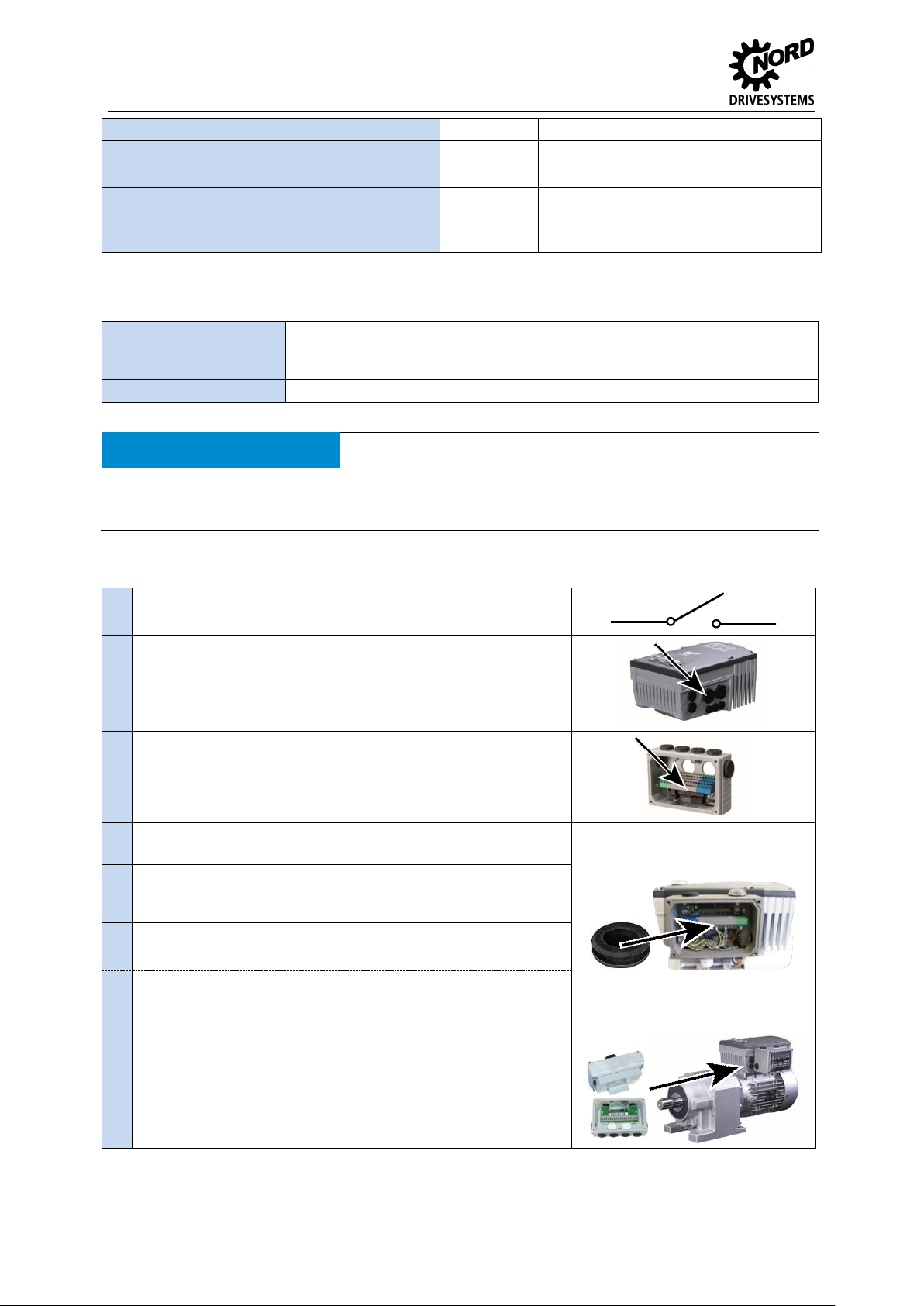
1.
Switch off the mains.
2.
Remove the two M25 caps on the required side of the frequency
inverter (right / left).
3.
Remove the printed circuit board (with terminal bar) from the
SK TI4-TU-…. connection unit.
4.
Install the SK TI4-TU- ... with the enclosed seal on the SK 2xxE
using the 4 enclosed bolts.
5.
Insert both of the enclosed grommets in the M25 cable glands (to
protect the internal wiring between the module and the frequency
inverter).
6.
Replace the printed circuit board (See point 3) and carry out the
electrical connections.
SK TI4-TU-…-C version devices: remove the top M20 cable gland
(however not at the diagnostic inlet) and insert the enclosed
membrane valve into this screw fitting.
7.
Fit and screw on the SK TU4 module.
Pos: 7 /Technische Informationen/IO - Er weiterung/Montage [SK TU4-IOE-xxx] @ 2\mod_1353315135994_388.docx @ 512 51 @ 6 @ 1
Installation
Installation steps for motor installation
2 TI 275281106 - 4912
Page 3
IO-Extension – SK TU4-IOE
1.
Switch off the mains.
2.
Attach the enclosed seal to the SK TI4-TU ... and place it on the
wall-mounting kit. Tightly screw the 2 oval-head screws (enclosed
with the wall-mounting kit) into the (countersunk) holes in the wallmounting kit from the outside.
3.
Insert and tighten the 2 bolts (enclosed with the wall-mounting kit)
from the inside into the freely accessible holes in the rear wall.
4.
Install the unit at the installation site and make the electrical
connections (maximum cable length 20m)
5.
Fit and screw on the SK TU4 module.
Information
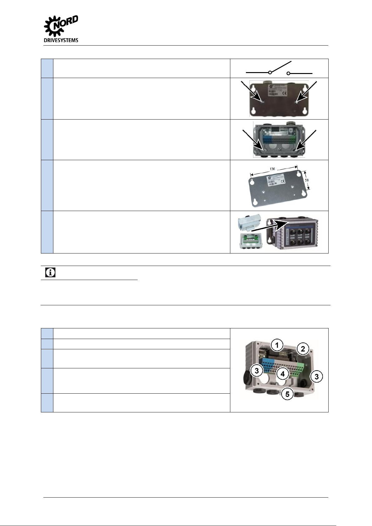
Contacts
The connection between the module and the connection unit is made by means of a pin connector. Terminals in
the terminal bar of the connection unit with an identical potential are connected by fitting the module and
connection unit together.
1.
No function, M20 x 1.5
2.
Diagnostic access, RJ12 socket
3.
M20 x 1.5 cable gland (1 on the left and 1 on the right):
incoming or outgoing cable, e.g. for system bus or 24V supply
4.
M25 x 1.5 cable gland (2x):
For wiring between the optional module and the frequency inverter
in case of direct attachment.
5.
M16x1.5 cable gland (4x):
For wiring of sensors, actuators, etc. Direct mounting.
Installation steps for wall-mounting
Details of BUS connection unit
TI 275281106 - 4912 3
Page 4

IO-Extension – SK TU4-IOE
Information
M12 round plug connectors
NORD supplies pre-assembled M12 flanged plug connectors for the production of detachable connections.
System
M12 connection extension
Article number
Profibus DP
SK TIE4-M12-PBR
275274500
CANopen
SK TIE4-M12-CAO
275274501
AS Interface
SK TIE4-M12-ASI
275274502
Analog initiators / actuators
SK TIE4-M12-INI
275274503
NORD system bus (outgoing)
SK TIE4-M12-SYSM
275274505
NORD system bus (incoming)
SK TIE4-M12-SYSS
275274506
24 V supply
SK TIE4-M12-POW
275274507
Analog initiators / actuators
SK TIE4-M12-ANA
275274508
Safe input (incoming)
SK TIE4-M12-SH
275274509
HTL encoder
SK TIE4-M12-HTL
275274512
AS interface with aux. power
SK TIE4-M12-ASI-AUX
275274513
These can be screwed directly into the M16 cable glands. By means of a suitable reducer (M20 to M16) the two
(M20) cable glands on both sided can also be used.
Terminals
Double-sprung
terminal bar
2 x 18 contacts
Cable cross section
AWG 14-26
rigid: 0,14 … 2,5 mm
flexible: 0.14 … 1.5 mm with wire end sleeves
PE connection
Via housing
RJ12
RJ45 - socket
Interface for connecting a parameterisation tool
SK TU4-IOE
SK 2xxE
VI 24V
GND/0V
SYS +
SYS -
24V
GND/0V
SYS +
SYS -
Pos: 10 /Technische Informationen/IO - Erweiterung/Anschlüsse [SK TU4-IOE] @ 2\mod_1353315262442_388.docx @ 51 276 @ 6 @ 1
Connections
Connection of the signal and control cables is made via the connection unit SK TI4-TU-BUS.
Schematic circuit diagram of electrical connection
(Terminal designations in example: Frequency inverter SK 2xxE)
4 TI 275281106 - 4912
Page 5

IO-Extension – SK TU4-IOE
Potential
Contact
Designation
Description
Analog IOs
1
VO 10V
10 V Reference voltage
2
VO 10V
10 V Reference voltage
3
AIN1+
Analog input 1, positive
4
AIN2+
Analog input 2, positive
5
AIN1-
Analog input 1, negative
6
AIN2-
Analog input 2, negative
7
AGND/0V
Analog Ground (internally connected to terminal 40)*
8
AGND/0V
Analog Ground (internally connected to terminal 40)*
9
AOUT
Analog Out
10
PE
PE
System bus level and digital inputs
11
VI 24V
Supply voltage (+24 V - in)
12
VI 24V
Supply voltage (+24 V - in)
13
VI 24V
Supply voltage (+24 V - in)
14
SYS +
System bus data cable +
15
GND/0V
Reference potential (0 V / GND)
16
SYS -
System bus data cable -
17
GND/0V
Reference potential (0 V / GND)
18
GND/0V
Reference potential (0 V / GND)
19
DIN1
Digital input 1
20
DIN3
Digital input 3
21
GND/0V
Reference potential (0 V / GND)
22
GND/0V
Reference potential (0 V / GND)
23
VI 24V
Supply voltage (+24 V - in)
24
VI 24V
Supply voltage (+24 V - in)
25
DIN2
Digital input 2
26
DIN4
Digital input 4
27
GND/0V
Reference potential (0 V / GND)
28
GND/0V
Reference potential (0 V / GND)
29
VI 24V
Supply voltage (+24 V - in)
30
VI 24V
Supply voltage (+24 V - in)
Digital outputs
31
VI 24V2
Supply voltage (+24 V - in) for digital outputs
32
GND2/0V2
Reference potential (0 V / GND) of digital outputs
33
DOUT1
Digital output 1
34
DOUT2
Digital output 2
35
GND2/0V2
Reference potential (0 V / GND) of digital outputs
36
GND2/0V2
Reference potential (0 V / GND) of digital outputs
Diagnostic socket
RJ12 - 1
RS485_A
Data cable RS485
RJ12 - 2
RS485_B
Data cable RS485
RJ12 - 3
GND
Reference potential (GND)
RJ12 - 4
RS232_TxD
Data cable RS232
RJ12 - 5
RS232_RxD
Data cable RS232
RJ12 - 6
24 V
Supply voltage (+24 V)
* AGND/0V is internally connected to the reference voltage of the module GND/0V via a special
component. In order to prevent damage to the module or faults in the analog signals, the two
contacts must not be bridged
Potential level
1 =
2 =
3 =
4 =
Analog IOs
System bus + DIN
DOUT
Diagnosis
Pos: 12 /Technische Informationen/IO - Erweiterung/Anschlussbeispiele [IOE Allg emein] @ 2\mod_1352736753713_388. docx @ 51105 @ 6 @ 1
Connection examples
The following connection examples are generally applicable for NORD IO modules. The number or
type of the available IOs and their configuration on the terminal rail varies according to the module.
The actual availability or the designation of the individual contacts should be obtained by reference to
the description of the connections. The technical data (e.g. load capacity) must be taken into account.
TI 275281106 - 4912 5
Page 6

IO-Extension – SK TU4-IOE
Control
voltage
source
Digital input
Digital output
External
supply
GND/0V
VI 24V
DIN
DIN
GND2/0V2
DOUT
VI 24V2
GND2/0V2
VI 24V
DOUT
VI 24V2
GND/0V
Internal supply
GND/0V
VO 24V
DIN
DIN
GND2/0V2
VO 24V
DOUT
VI 24V2
GND/0V
Signal type*
Analog / Differential input
Analog output
0/2 … 10 V
0/4 … 20 mA
-10 … 10 V**
VO 10V
AGND/0V
AIN -
AIN +
AGND/0V
AOUT
Potentiometer
(10 kΩ)
0 … 10 V
VO 10V
AGND/0V
AIN AIN +
R=10kΩ
* The relevant IOs must be configured via DIP switches according to the form of the signal
** Analog input only
Note
Broadcast mode
In "Broadcast mode, which is activated via the parameter (P162), the module can access up to 4 inverters in
parallel. Therefore the frequency inverters jointly access the I/Os and evaluate the input signals according to their
own parameterisation. Output signals from the frequency inverters which are sent to the common IO module are
linked by a logical "OR" within the module. i.e. a digital output is set as soon as one of the four frequency inverters
addresses it. In addition, the highest analog value is provided via the analog output of the IO extension.
Digital signals
Analog signals
Pos: 13 /Technische Informationen/IO - Erweiterung/Konfiguration [IOE Allgemein] @ 2\mod_1352388400441_388.doc x @ 50928 @ 6 @ 1
Configuration
Configuration of the module is mainly performed via the DIP switches. The DIP switches are read after
a "power on" of the module. A change to the DIP switch during operation has no effect.
The system bus must be terminated at both of its physical ends (if necessary set the "System bus
termination resistor" DIP switch).
6 TI 275281106 - 4912
Page 7

DIP switches
Function
DIP-Switch
Meaning
DIP-Switch
Combinations
Assignment
Signal
(DIP-No.)
BIT2
BIT1
BIT0
System bus
termination
resistor
S-Bus Term.
(01)
0 1 not set
setting
Addressing
system bus
S-Bus Adr. Bit 0
(02)
0
0
1
1
0
1
0
1
Adr. 20 (for FI 0 Adr. 32)*
Adr. 21 (for FI 1 Adr. 34)*
Adr. 22 (for FI 2 Adr. 36)*
Adr. 23 (for FI 3 Adr. 38)*
S-Bus Adr. Bit 1
(03)
Analog input
AIN1
Ain1 Mode Bit 0
(04)
0
0
0
1
1
0
0
1
0
0
0
1
0
0
1
0 … 10 V
2 … 10 V
-10 … 10 V
0 … 20 mA
4 … 20 mA
Ain1 Mode Bit 1
(05)
Ain1 Mode Bit 2
(06)
Analog input
AIN2
Ain2 Mode Bit 0
(07)
0
0
0
1
1
0
0
1
0
0
0
1
0
0
1
0 … 10 V
2 … 10 V
-10 … 10 V
0 … 20 mA
4 … 20 mA
Ain2 Mode Bit 1
(08)
Ain2 Mode Bit 2
(09)
Analog output
AOUT
Aout Mode Bit 0
(10)
0
0
1
1
0
1
0
1
0 … 10 V
2 … 10 V
0 … 20 mA
4 … 20 mA
Aout Mode Bit 1
(11)
Mode
Second - IOE
2nd IOE Mode
(12)
0 1 First SK-…-IOE on FI
Second SK-…-IOE on FI
* With DIP12 = ON: Address 10 … 13 instead of 20 … 23
DS
(Device State)
DE
(Device Error)
Meaning
Long flashing = 0.5 s on / 1 s off
Short flashing = 0.25 s on / 1 s off
OFF
OFF
Technology unit not ready, no control voltage
ON
OFF
Technology unit ready, no error, at least one frequency inverter is communicating via the system bus
ON
Short flashing
Technology unit ready, however
• One or more of the connected frequency inverters is in fault status
Long flashing
OFF
Technology unit ready and at least one further participant is connected to the system bus, but
• No frequency inverter on the system bus (or connection interrupted)
• Address error for one or more system bus participants
Long flashing
Short flashing
Flash interval
1 x - 1s pause
System bus is in status "Bus Warning"
• Communication on system bus interrupted or
• No other participant present on the system bus
Long flashing
Short flashing
Flash interval
2 x - 1s pause
• System bus is in status "Bus off" or
• The system bus 24V power supply was interrupted during operation
Long flashing
Short flashing
Flash interval
3 x - 1s pause
• No system bus 24V power supply (system bus is in status "Bus off")
Long flashing
Short flashing
Flash interval
4 x - 1s pause
Module error
• EEPROM error
Long flashing
Short flashing
Flash interval
5 x - 1s pause
Module error
• AOUT error (analog output)
• DIP switch configuration error
OFF
Short flashing
Flash interval
1…7 - 1s pause
System error, internal program sequence interrupted
• EMC interference (observe wiring guidelines!)
• Module faulty
IO channel
Display
Meaning
IO channel
Display
Meaning
DI 1
ON
High potential DIN1
DO 1
ON
High potential DOUT1
DI 2
ON
High potential DIN2
DO 2
ON
High potential DOUT2
DI 3
ON
High potential DIN3
DI 4
ON
High potential DIN4
DI 3/4, DO 1/2
Available according to the type of IO
module
IO-Extension – SK TU4-IOE
Pos: 14 /Technische Informationen/IO - Erweiterung/LED Anzeigen [IOE Allgemein ] @ 2\mod_1352390573890_388.docx @ 51028 @ 6 @ 1
LED Displays
Pos: 15 /Technische Informationen/IO - Erweiterung/Fehlermeldungen [IOE Allge mein] @ 2\mod_1352389805965_388.doc x @ 50953 @ 6 @ 1
TI 275281106 - 4912 7
Page 8

IO-Extension – SK TU4-IOE
Error
Meaning
Comments
1000
EEPROM error
EMC fault, module defective
1030
System bus OFF
No 24 V supply to bus, connections not correct
2000
DIP switch changed
DIP switch configuration changed during operation
2001
DIP switch configuration incorrect
Invalid DIP switch settings
2010
Error at analog output
Overload, reference voltage, short-circuit, calibration error
2020
Inverter does not support the module
Incorrect inverter type connected
Parameter
Meaning
Comments
(P514)
Bus speed
5 (= 250 kBaud)
(P515 [-01])
Bus address
FI 1 = 32
FI 2 = 34
FI 3 = 36
FI 4 = 38
(P480 [-01 …-08])
DIN function of the device
Possible settings according to (P420)
(P481 [-05 …-08])
DOUT function of the device
Possible settings according to (P434)
(P400 [-03 …-06])
AIN function of the device
Possible settings according to (P400)
(P418 [-02 …-03])
AUT function of the device
Possible settings according to (P418
Parameter
Meaning
Comments
(P150)
Set relays
Set DOUT directly or control via BUS
(P152)
Factory setting
Reset the module parameters, calibrate AOUT
(P153 [-01 …-02])
Minimum system bus cycle
Reduction of bus load due to the module
(P160)
Set analog output
Set AOUT directly or control via BUS
(P161 [-01 …-09])
Filter time
Debounce or round input signals
(P162)
Send broadcast
Activate Broadcast mode (control of several
inverters by this module)
(P163)
Invert analog output
Invert analog signal
(P170 [-01 … 02])
Present errors
Display of module errors
(P171 [-01 … 03])
Software version
Firmware version / Revision
(P172)
Configuration
Module type
(P173)
Module status
Status of system bus or connected FI
(P174)
Status of digital inputs
Display of DIN switching status
(P175)
Relay status
Display of DOUT switching status
(P176 [-01 … 03])
Actual voltage
Voltage level of analog signals
Document
Name
Document
Meaning
NORD CON
Parameterisation and diagnostic software
BU 0200
SK 2xxE frequency inverter manual
BU 0000
Description of NORD CON software
BU 0500
SK 5xxE frequency inverter manual
BU 0040
ParameterBox manual
Error messages
Error messages for the module - the present or archived messages for the last error - can be read out
via the module parameter (P170) (see Parameterisation).
Pos: 16 /Technische Informationen/IO - Erweiterung/Parametrierung [IOE Allgemein ] @ 2\mod_1352389903587_388.docx @ 50978 @ 6 @ 1
Parameterisation
Inverter: In order to establish communication between the inverter and the IOE module, the following
inverter parameters must be changed.
IO extension: The module provides a selection of parameters for setting or displaying special
operating values. The parameters can be changed with the aid of the NORDCON software or with a
ParameterBox. Communication is only possible via an SK 54xE or SK 2xxE which is connected to the
module.
Pos: 17 /Technische Informationen/IO - Erweiterung/Weiterführende Dokumentati onen und Software [IOE Allgemein] @ 2\ mod_1352390057120_388.docx @ 510 03 @ 6 @ 1
Further documentation and software (www.nord.com)
=== Ende der Liste für Textmarke Inhalt ===
8 TI 275281106 - 4912
 Loading...