

Page 1
This document is only valid in combination with the operating instructions of the respective frequency converter.
Technical Information / Datasheet
Pos: 1 /Technis c h e Inf ormation en/ SK xUx - Bus - Er weiterung en/Anschl usseinheit [SK TI4-TU-...]/ SK TI4-TU4-BUS / 27528000 0 / Basisi nformation en [SK TI4-TU- BUS] @ 3\mod_1364462881517_388.docx @ 62842 @ 555 @ 1
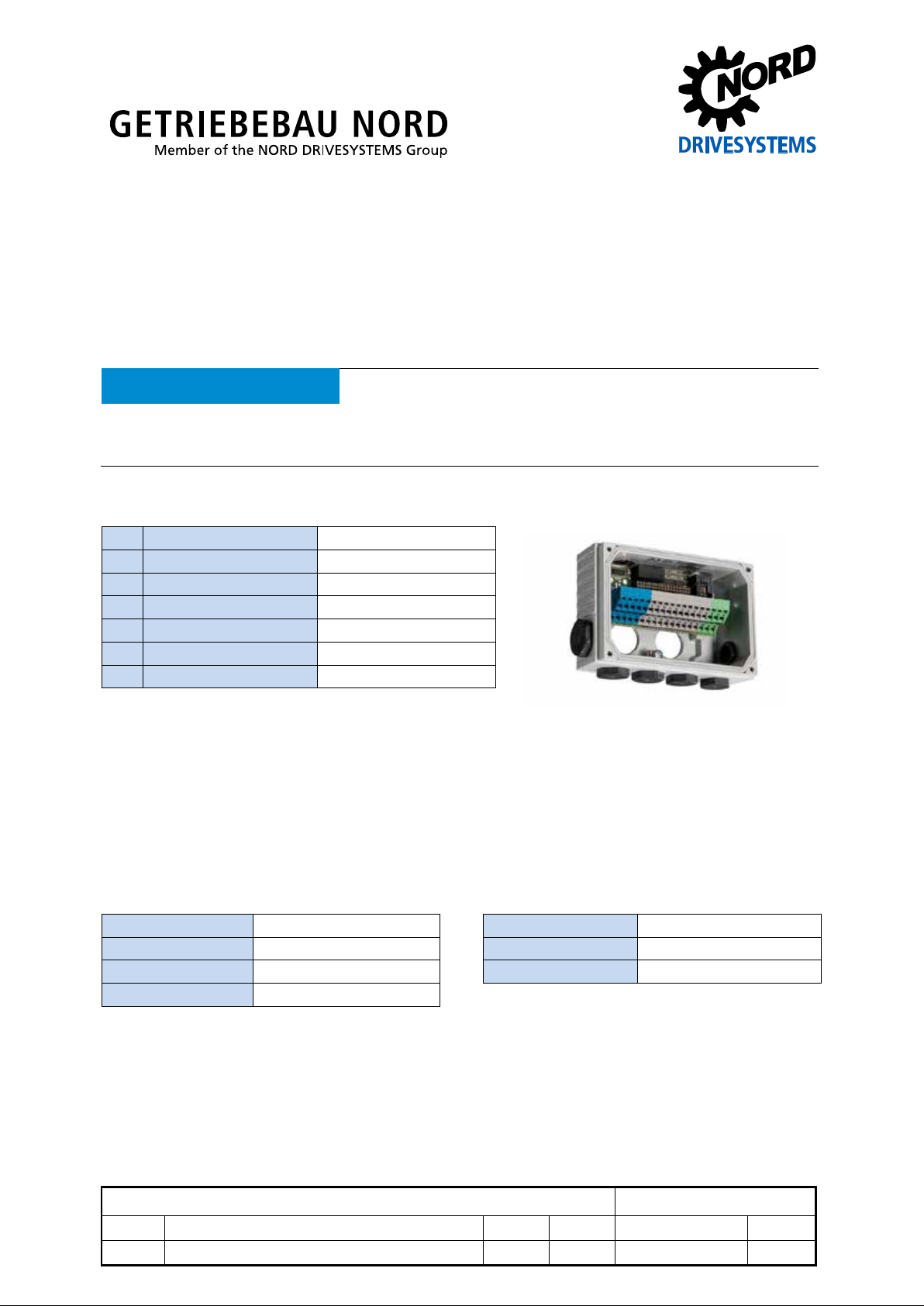
SK TI4-TU-BUS
Part number: 275 280 000
Bus connection unit
ATTENTION
All of the information that is relevant for a safe start-up of this assembly and the frequency converter is only
available under these conditions.
Validity of document
Scope of delivery
1 x Bus connection unit SK TI4-TU-BUS
1 x System bus cable set grey / black
1 x 24 VDC cable set brown / blue
1 x PE cable green / yellow
1 x Gasket 2 mm self-adhesive
2 x Leadthrough grommet 22 mm x 9.5 mm
4 x Hexagon socket M4 x 20
Usage area
The bus connection unit f orms the basis for the bus options and IO - expansions of model SK TU4-.
The terminal strip is divide d into thr e e pot ent ia l leve ls . T he func tions of the in di vid ual terminals depend
on the selected field bus or IO - expansion, and are no t defined until both elem ent s are j oined t oge ther
(BUS connection un it and f ield bus or IO expansio n). The BUS - connection u nit can b e installed onto
or in the immediate vicinity of a frequency converter (SK 180E … SK 2xxE).
Technical data
Temperature range -25 °C … 50 °C Vibration resistance 3M7
Temperature class Class 3K3 Hardware version BB
Protection class IP55 Dimensions [mm] H x W x D: 95 x 136 x 55
Current rating 3A
Pos: 3 /Technis c h e Inf ormation en/ SK xUx - Bus - Er weiterung en/Anschl usseinheit [SK TI4-TU-...]/M erkmale [SK TI 4-TU-BUS] @ 3\mod_1364469965939_388.docx @ 62995 @ 5 @ 1
Connection unit SK TI4-TU-BUS
1.0 Erstausgabe / first issue 1613 Rck TI 275280000 GB
version reason for change(s) issue name document speech
Page 2
Connection unit – SK TI4-TU-BUS
Incoming or outgoing line for system bus or 24 V supply, for
Leadthrough for wiring between optional assembly and frequency
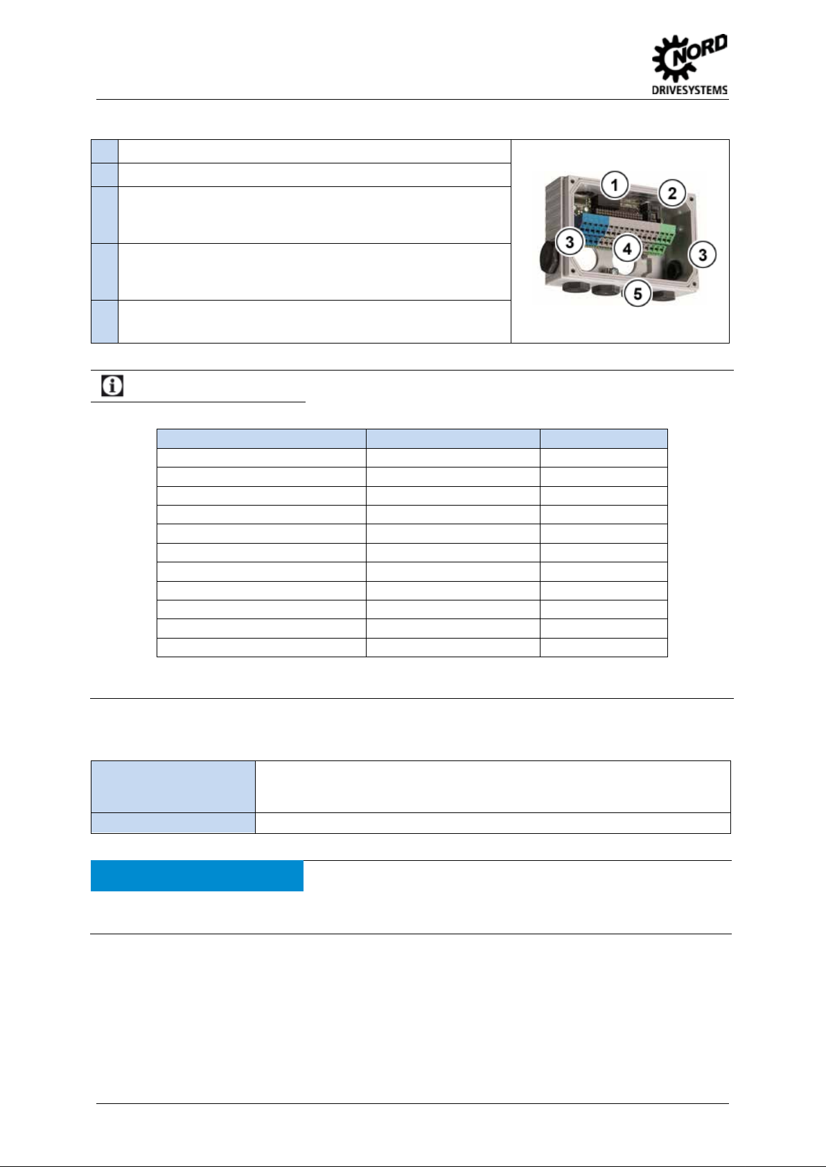
Features
1. No function, M20 x 1,5
2. Diagnosis access, RJ12 socket
3.
Cable entry M20 x 1.5 (1 on left, 1 on right):
example
4.
Cable entry M25 x 1.5 (2 pcs.):
converter with direct attachment.
5.
Cable entry M16x1.5 (4 pcs.):
Leadthrough of wiring to sensors, actuators etc., direct attachment
Information
NORD can supply prefabricated M12 connection expansions for manufacturing plug-in connecti ons .
System M12 connection expansion Part . No.
Profibus DP SK TIE4-M12-PBR 275274500
CANopen SK TIE4-M12-CAO 275274501
AS Interface SK TIE4-M12-ASI 275274502
AS Interface with aux. power SK TIE4-M12-ASI-AUX 275274513
Initiators / actuators SK TIE4-M12-INI 275274503
NORD system bus (outgoing) SK TIE4-M12-SYSM 275274505
NORD system bus (incoming) SK TIE4-M12-SYSS 275274506
24 V supply SK TIE4-M12-POW 275274507
Analog initiators / actuators SK TIE4-M12-ANA 275274508
Safe input (incoming) SK TIE4-M12-SH 275274509
HTL transmitter SK TIE4-M12-HTL 275274512
These can be screwed directly into the M16 cable lead-ins. The two existing side cable lead-ins (M20) can be
used if a suitable reducer is used.
M12 connector
Pos: 4 /Technis c h e Inf ormation en/ SK xUx - Bus - Er weiterung en/Anschl usseinheit [SK TI4-TU-...]/M ontage [SK TI 4-TU-xxx] @ 3\mod_1364470201374_388.docx @ 63045 @ 5 @ 1
Installation
Installation location To the left or right of the frequency converter connection unit.
Alternatively using the wall mounting kit SK TIE4-WMK-TU (Mat no.: 275 274 002,
TI 275274002) near the converter
Mounting Using screw connection (4 x hexagon socket M4 x 20)
ATTENTION
Ensure that no leaks are present during installation (assembly, cable leadthroughs, cable glands) in order to
avoid penetration by moisture and therefore the risk of corrosion and short circuiting.
2 TI 275280000 - 1613
Sealing
Page 3

Connection unit – SK TI4-TU-BUS
Remove the two M25 blind caps from the relevant side of the
(with terminal strip) from connection unit
Insert both of the provided leadthrough grommets into the M25
leadthroughs (to protect internal wiring between assembly and
(see point 3) and make the electrical
kit accessory pack) into the provided holes (countersunk) from the
the freely accessible holes in the rear panel from the inside and
The installation steps desc r ibe d in the following are val id f or att ac hing a connection unit of the o pti ona l
assemblies (SK TI4-TU- NET / BUS / MSW) to a frequency converter in model series SK 180E /
SK 190E and SK 2xxE).
Installation steps for attachment to frequency converter
1. Switch off the mains power.
2.
frequency inverter (right / left).
3.
Remove circuit board
SK TI4-TU-….
4. Fit provided seal to SK TI4-TU-…. connection unit and fit to device
with the 4 provided screw bolts.
5.
frequency converter).
6.
Re-install circuit board
connection.
7. Fit SK TU4 assembly and screw in place.
Wall mounting assembly steps
1. Switch off the mains power.
2. Install provided seal to SK TI4-TU-…. connection unit and attach to
wall mounting kit. Screw the 2 cheese-head screws (wall mounting
outside.
3. Insert the two screw bolts (wall mounting kit accessory pack) into
screw in place.
Install unit at usage location and make electrical connection (cable
4.
length max 20m).
5. Attach SK TU4 assembly and screw in place.
TI 275280000 - 1613 3
Page 4

Connection unit – SK TI4-TU-BUS
board. The terminals of the terminal strip in the BUS connection unit with identical potential are not connected to
Double tension
If installed to converter:
make connection to PE of
Interface for connecting
Document
Name
Document
Meaning
TI 275274002
Various
Data sheets for connection expansions
Information
Contacting
The connection between the field bus or IO - expansion and the BUS connection unit is made using a socket
each other until the field bus or IO - expansion and the BUS connection unit are connected to each other.
Pos: 6 /Technis c h e Inf ormation en/ SK xUx - Bus - Er weiterung en/Anschl usseinheit [SK TI4-TU-.. .]/Anschlüs se [SK TI 4-TU-BUS(-C)] @ 3 \mod_1364476178630_388.docx @ 63100 @ 5 @ 1
Connections
1 Terminal strip
spring terminal
strip
Wire cross-
AWG 14-26 rigid: 0.14 … 2.5 mm²
section
2 PE connection via housing
3 Diagnosis RJ12 socket
2 x 18 contacts
flexible: 0.14 … 1.5 mm² with
wire end sleeves
converter using the provided
cable (green/yellow).
parameterisation tool
Details of the functional ass ignment of the terminals can be found in the techn ical information of the
relevant bus option or IO expansion of the SK TU4-.
Pos: 7 /Technis c h e Inf ormation en/ SK xUx - Bus - Er weiterung en/Anschl usseinheit [SK TI4-TU-...]/Weiterführende Dokument ationen und Softwa r e [SK TI4-TU-...] @ 3\mod_1364480506538_388.docx @ 63125 @ 5 @ 1
Additional documentation and software (www.nord.com)
Wall mounting kit for SK TIE4-WMK-TU
=== Ende der Liste für Textmar ke Inhalt ===
4 TI 275280000 - 1613
 Loading...