

NORD TI 275274603 User Manual
Connection extension
SK TIE4-RS232-RS485
1.0
Erstausgabe / first issue
2713
Rck
TI 275274603
GB
version
reason for change(s)
issue
name
document
speech
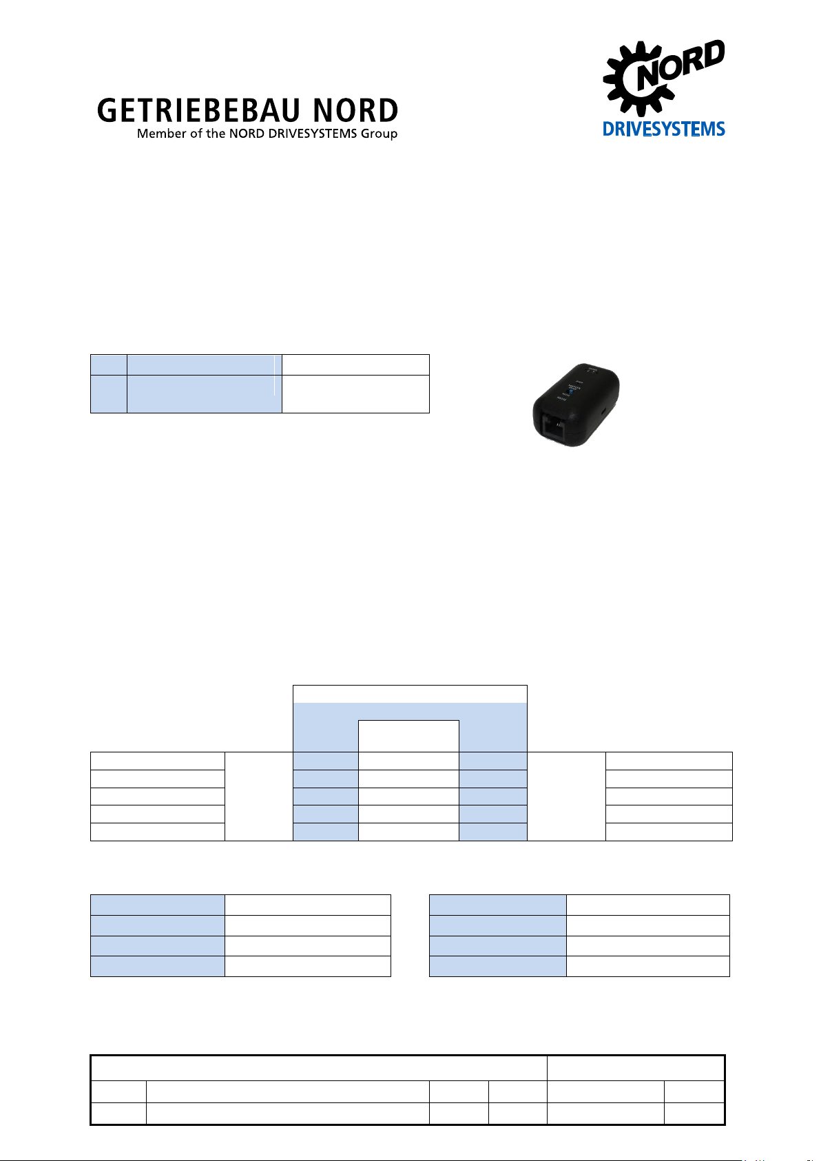
SK TIE4-RS485-RS232
Part number: 275 274 603
Interface converter connection extension
1 x
Module
SK TIE4-RS485-RS232
1 x
Connection cables
RJ12 RJ12
(L = approx. 10 cm)
Converter
DIP switch position for "master"
RS 232
Direction of
communication
RS 485
SK 1x5E
RS 232
√
RS 485
SK PAR-3E / -3H
SK 1x5E
√
SK CSX-3E / -3H
PC (NORD CON)
√
SK 180E / SK 190E
PC (NORD CON)
√
SK 2xxE
PC (NORD CON)
√
SK 5xxE
Temperature range
0 … 40 °C
Interfaces
RS 232 or RS 485
Protection class
IP20
Connection
2 x RJ12 plug sockets
Weight
25 g
Dimensions
LxWxH = 56x31x24 [mm]
RS485 termination
120 Ω, fixed
Technical Information / Datasheet
Pos: 1 /Technische Informationen/Ansc hlusserweiterungen [HAN, HQ,SK TIE]/U msetzer RS 232-RS485/SK TIE4-RS4 85-RS232 / 275274603 / Basisinform ationen [SK TIE4-RS485-RS232] @ 3\mod_1372666043302_388.docx @ 8024 3 @ 5555 @ 1
Scope of delivery
Field of use
Signal converter from RS 485 to RS 232. This is used to connect a device with an RS 232 interface to
another device with an RS 485 interface.
Use
The converter is intended for the following device combinations. The DIP switch must be set according
to the combination (see also "Configuration").
For SK 180E ... SK 5xxE series devices, no converter is required for communication with a PC, as the
devices are also equipped with an RS 232 interface. The converter only needs to be connected in
case one or more devices are to be connected to the PC via an RS 485 interface.
Technical data
Pos: 2 /Technische Informationen/Ansc hlusserweiterungen [HAN, HQ,SK TIE]/U msetzer RS 232-RS485/LED Anzeige n [SK TIE4-RS485-RS232] @ 3\mod_ 1372669872055_388.docx @ 80295 @ 5 @ 1
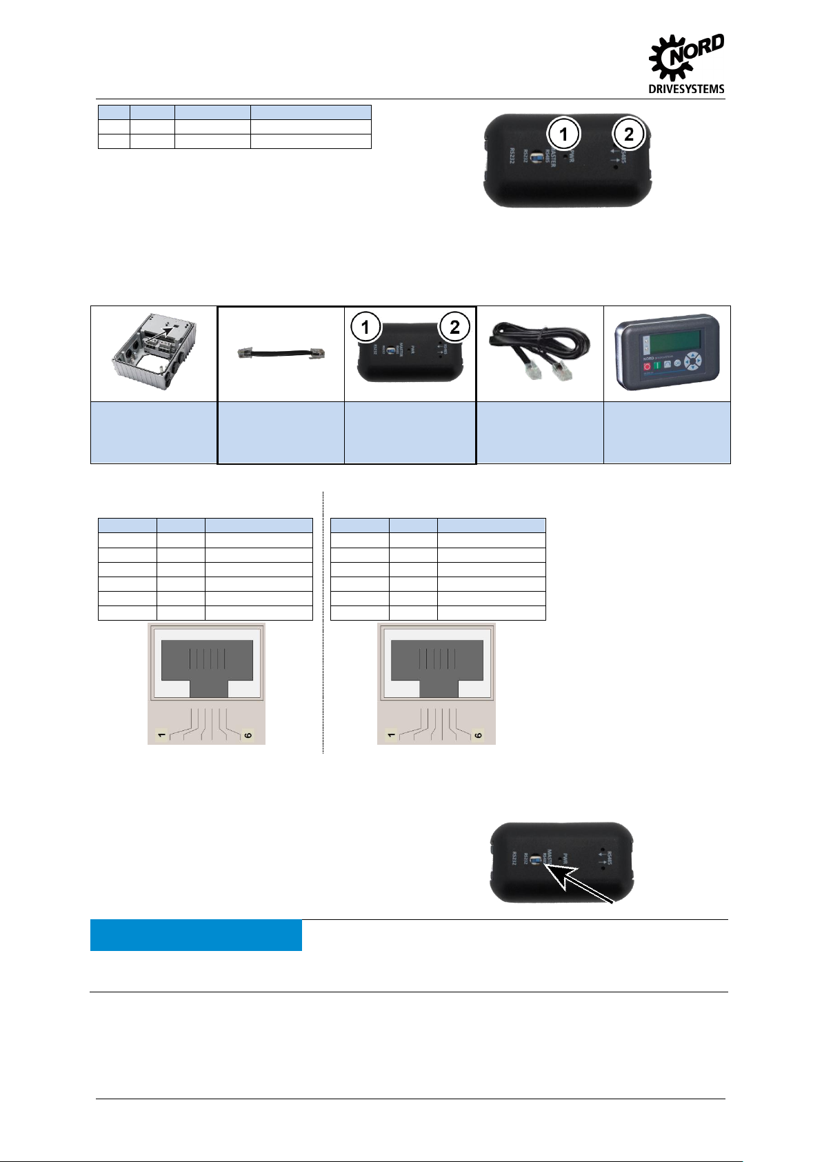
LED indicators
The operating statuses of the module are visualised using LED indicators.
Connection extension – SK TIE4-RS232-RS485
No.
Name
Colour
Meaning
1
PWR
Green
Ready for operation
2*
RS485
2x Yellow
Communication active
* Each LED indicates an intact communication direction. If an LED
does not illuminate, this indicates a fault or interruption in the relevant
communication direction.
Starter
(Interface: RS 232)
Connection cable
RJ12 – RJ12
(Enclosed with
converter)
Converter
SK TIE4-RS485-
RS232
Connection cable
RJ12 – RJ12
(enclosed with
ParameterBox)
ParameterBox
(Interface: RS 485)
( 1 ) Detail RJ12 – RS232
( 2 ) Detail RJ12 – RS485
Contacts 3 and 6 are
connected through! The load
must not exceed 500 mA!
RJ12 Pin
Signal
Description
1
n.c. 2
n.c. 3
GND
Earth 4 TXD
Transmission Data
5
RXD
Receive Data
6
+24V-
24 V ± 20 %
RJ12 Pin
Signal
Description
1
A (+)
RS485_A
2
B (-)
RS485_B
3
GND
Earth 4 n.c. 5
n.c. 6
+24V-
24 V ± 20 %
Configuration of the converter is restricted to a DIP switch on
the front side of the converter. This determines the interface
on which the master is located.
No communication is possible if the DIP switch is not
set correctly.
ATTENTION
Possible damage to devices
Care must be taken that only one participant takes on the master function. Failure to observe this may cause
damage to the relevant drivers.
Pos: 3 /Technische Informationen/Ansc hlusserweiterungen [HAN, HQ,SK TIE]/U msetzer RS 232-RS485/Anschlüsse [SK TIE4-RS485_RS232] @ 3\mod_137 2674444498_388.docx @ 80447 @ 5 @ 1
Connections
The converter is connected between e.g. the motor starter and the ParameterBox (see below).
Pos: 4 /Technische Informationen/Ansc hlusserweiterungen [HAN, HQ,SK TIE]/U msetzer RS 232-RS485/Konfiguration [SK TIE4-RS485-RS232] @ 3\mod_13 72670309640_388.docx @ 80376 @ 5 @ 1
Configuration
=== Ende der Liste für Textmarke Inhalt ===
2 TI 275274603 - 2713
 Loading...