

NORD TI 275271006 User Manual
IO-Extension
SK CU4-IOE
1.0
Erstausgabe / first issue
4912
Rck
TI 275271006
GB
version
reason for change(s)
issue
name
document
speech
SK CU4-IOE
Part Number 275 271 006
IO Extension
NOTICE
Validity of this document
This document is only valid in conjunction with the operating manual supplied for the respective frequency
inverter. It is essential that all the relevant information is available for the safe commissioning of this module and
the frequency inverter.
1 x
Module
SK CU4-IOE
1 x
System bus cable kit
grey / black
1 x
24 VDC cable kit
brown / blue
2 x
Connection screws
M4 x 20 cross-head
Temperature range
-25°C … 50 °C
Vibration resistance
3M7
Temperature class
Class 3K3
Firmware version
V1.2 R0
Protection class
IP20
Name
Terminal
Data
Module power supply (load capacity)
40/44
24 VDC ± 20 %, reverse polarity protected
(≤ 2 A)
Power consumption of module
40/44
≈ 110 mA
Digital input - operating range
C1 … C2
Low: 0 V … 5 V, High: 15 V … 30 V
Digital input - specific information
C1 … C2
Ri = 8,1 kΩ, input capacitance: 10nF
Scan rate 1 ms, reaction time 1 ms
Analog input - reference voltage
11
10 VDC ±0,1 V, ≤ 20 mA (output)
Analog input - differential input version
13/14; 15/16
Resolution: 12 Bit, accuracy: 0.1 V
Analog output - load capacity
17
≤ 10 mA (Mode: 0/2 … 10 V)
≤ 20 mA (Mode: 0/4 … 20 mA, at 5 V)
Analog output - specific information
17
Resolution: 10 Bit, accuracy: 0.25 V
Pos: 2 /Technische Informationen/IO - Er weiterung/SK CU4-IOE / 275271006 /SK CU 4-IOE / 275271006 / Basisinformatione n [SK CU4-IOE] @ 2\mod_1352823805 880_388.docx @ 51131 @ 6666 @ 1
Technical Information / Datasheet
Scope of supply
Field of use
IO extension for installation in a decentralised inverter SK 2xxE. This can be connected to the inverter
via the system bus. Two digital inputs, 2 analog inputs and 1 analog output are available.
Technical Data
IO-Extension – SK CU4-IOE
Installation location
Inside the connection unit of a frequency inverter (SK 2xxE)
Fastening
With screw fasteners
Terminals
Screw terminals
1 terminal bar, with 16 connections, (5 mm spacing)
Cable cross section
0,14 … 2,5 mm
AWG 14-26
PE connection
Via inverter
Via screws if installed in inverter
SK CU4-IOE
SK 2xxE
VI 24V
GND/0V
SYS +
SYS -
24V
GND/0V
SYS +
SYS -
Level
Contact
Designation
Description
System bus level,
digital signals
44
VI 24V
Supply voltage (+24 V - in)***
40
GND/0V
Reference potential (0 V / GND)***
C1
DIN1
Digital input 1
C2
DIN2
Digital input 2
77
SYS+
System bus data cable +**
78
SYS-
System bus data cable -**
40
GND/0V
Reference potential (0 V / GND)
Analog signals
11
VO 10V
10 V Reference voltage
14
AIN1+
Analog input 1, positive
13
AIN1-
Analog input 1, negative
12
AGND/0V
Analog Ground (internally connected to terminal 40)*
17
AOUT
Analog Out
11
VO 10V
10 V Reference voltage
16
AIN2+
Analog input 2, positive
15
AIN2-
Analog input 2, negative
12
AGND/0V
Analog Ground (internally connected to terminal 40)*
* AGND/0V is internally connected to the reference voltage of the module GND/0V via a special
component. In order to prevent damage to the module or faults in the analog signals, the two
contacts must not be bridged
** Use system bus cable kit (included in scope of delivery), black = SYS -, grey = SYS +
*** Use 24VDC cable kit (included in scope of delivery), brown = 24V, blue = GND/0V
Installation
Pos: 9 /Technische Informationen/IO - Er weiterung/Anschlüsse [SK CU4-IOE] @ 2\mod_1353314893934_388.docx @ 5122 6 @ 6 @ 1
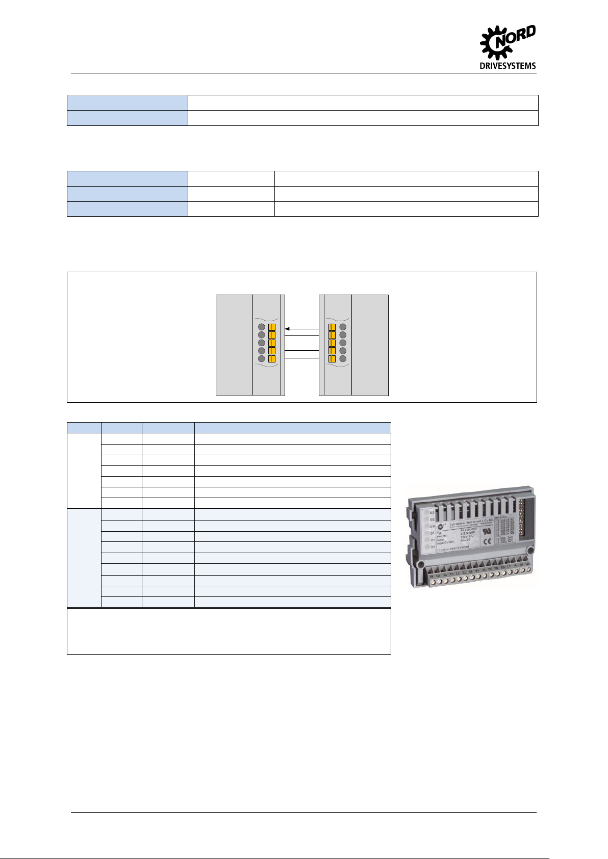
Connections
Schematic circuit diagram of electrical connection
(Terminal designations in example: Frequency inverter SK 2xxE)
Pos: 12 /Technische Informationen/IO - Erweiterung/Anschlussbeispiele [IOE Allg emein] @ 2\mod_1352736753713_388. docx @ 51105 @ 6 @ 1
Connection examples
The following connection examples are generally applicable for NORD IO modules. The number or
type of the available IOs and their configuration on the terminal rail varies according to the module.
The actual availability or the designation of the individual contacts should be obtained by reference to
the description of the connections. The technical data (e.g. load capacity) must be taken into account.
2 TI 275271006 - 4912
 Loading...