

Page 1
This document is only valid in combination with the operating instructions for the relevant drive unit. All of the
up of this module and the drive unit is only available under these
Technical Information / Datasheet
Pos: 2 /Tec hnische Inf ormation en/Zubehör/ Platine_P egelwandl er_Contelec tgeber/Pl atine Pegel anpassung HTL - HTL A+/ - B+/- / 185520 95 / Basisi nformati onen [ - HTL -HTL+ /-] @ 4\mod_1385464912683_388.docx @ 106965 @ 555 @ 1
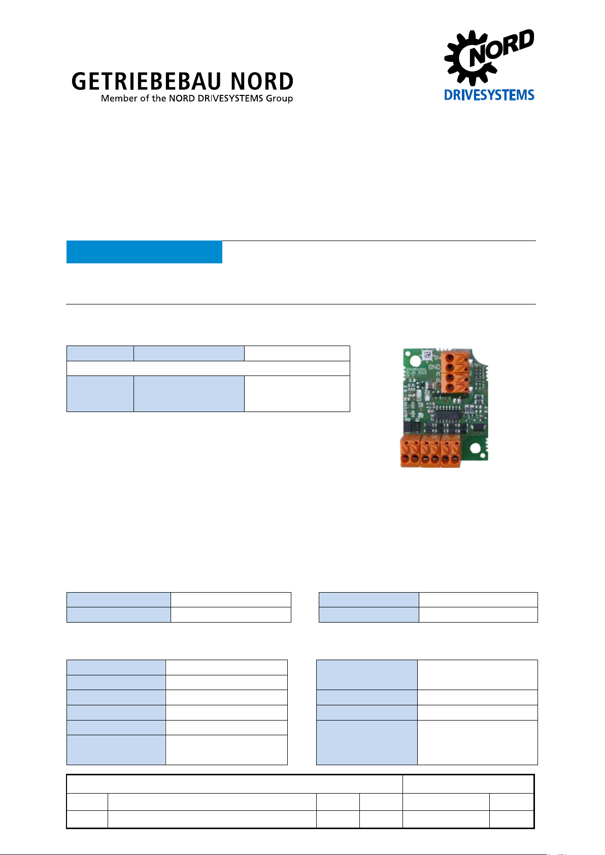
Level adapter PCB HTL – HT L A+ / - B+/-
Part number: 18 552 095
Level adapter HTL – HTL A+/- B+/-
NOTICE
information that is relevant for a safe startconditions.
Validity of the documents
Scope of delivery
1 x Module PCB, lacquered
Accessories required
1 x Mounting kit
OBW MOUNTING KIT
PCB 185520xxx
(Part No. 18552160)
Usage area
The module, which is inten ded for installat ion in the motor term inal box, is us ed to c onvert HT L or TTL
signals into complementary HTL signals. With this form of signal, the probability of errors in data
transmission is cons idera bly re duced. Use of this m odule is recom m ended for ca ble lengt hs i n exces s
of 30 m.
Technical data
Module
Ambient temperature -25°C … +75 °C Weight 20 g
Protection class IP00 Dimensions [mm] L x W x H: 46 x 35 x 22
Electrical data
Electrical connection Spring terminals Cross-section 20-16 AWG
Input voltage 10 … 30 V DC Connection terminals (0.5 – 1.5 mm2)
Input level "0" ≤ 0.8 V Power consumption 10 mA (own consumption)
Input level "1" ≥ 2.4 V Max. frequency 100 kHz
Max. output voltage = Input voltage Max. cable length 500 m at 20 kHz
Typical output current: 100 mA
dynamic: 200 mA
Level adapter PCB HTL - HT L A+/- B+/-
V1.0 Erstausgabe / first issue 4813 Rck TI 18552095 GB
version reason for change(s) issue name document speech
Page 2
Level adapter PCB – HTL - HTL A+/- B+/-
2 x
Toothed washers
6 x
Plastic washers
Information
Motor terminal box
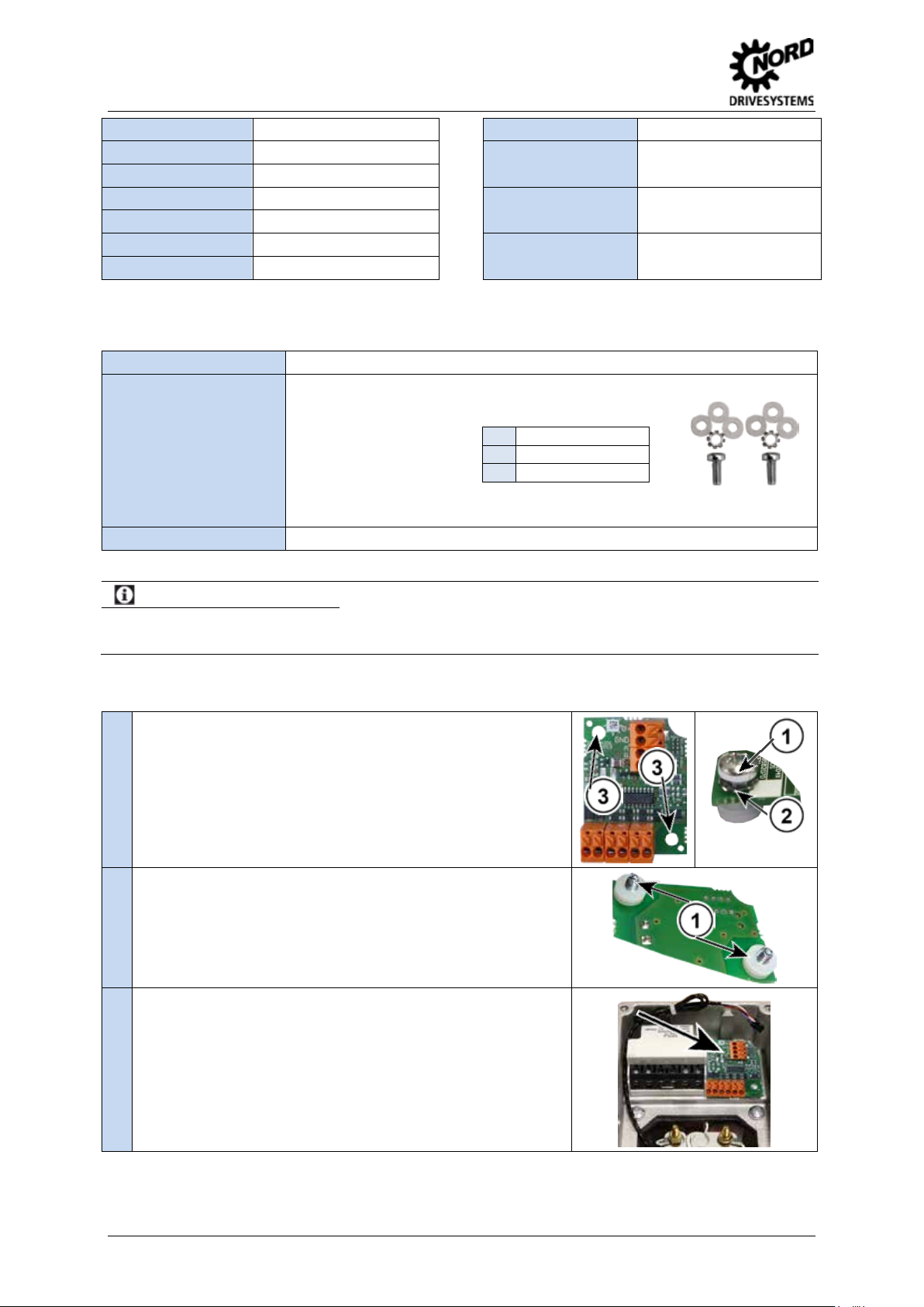
Insert the M4 screws (1) with toothed washers (2) from above into
Signal delay Tests
Rising flank 250 ns EN61000-4-2 ESD 4 kV contact discharge
Falling flank 750 ns 8 kV air discharge
Protection EN61000-4-4 Burst 1 kV signal cables
power supply Reverse polarity protected 2 kV power supply
Outputs Short-circuit protected EN61000-4-5 Surge 1 kV signal cables
Overtemperature Switch-off at 150°C 2 kV power supply
Pos: 3 /Tec hnische Inf ormation en/Zubehör/ Platine_P egelwandl er_Contelec tgeber/Mo ntage [Plat ine Pegel anpassung ] @ 4\mod_1380536273119_388.docx @ 100204 @ 5 @ 1
Installation
Installation location In motor terminal box
Mounting Double screw fastening with installation kit (Part No.: 18552160)
Installation kit consisting of: 2 x M4 screws
Illustration of installation
kit
Tools Slot-head screwdriver 0.6 x 3.5
The PCB is installed in an adequately dimensioned motor terminal box. Installation in a one-piece terminal box
(EKK) is not possible.
1.
the holes provided (3).
2. Put 3 plastic washers (1) onto each screw from the underside.
3. Screw the PCB into the terminal box.
Pos: 4 /Tec hnische Inf ormation en/Zubehör/ Platine_P egelwandl er_Contelec tgeber/Ans chlüsse [ Platine Peg elanpass ung HTL ... ] @ 4\mod_1380537501717_388.docx @ 100255 @ 5 @ 1
2 TI 18552095 - 4813
Page 3

Level adapter PCB – HTL - HTL A+/- B+/-
Connect the signal cable according to the adjacent
Incremental encoder
Frequency inverters
Incremental
Level adapter PCB HTL –
Evaluation device (e.g.
Connections
illustration.
1
2
Pos: 6 /Tec hnische Inf ormation en/Zubehör/ Platine_P egelwandl er_Contelec tgeber/El ektrischer Anschluss HTL_TTL a uf HTL + - ( B ei s piel) @ 4\mod_1385466527697_388.docx @ 107016 @ @ 1
Electrical connection (example)
encoder
HTL A+/- B+/-
Pos: 7 /Technis c h e Inf ormation en/ Zubehör/P l atine_Peg el wandler_C ontelectg eb er/Weiterf ührende Do k u me nt ationen und So ftware @ 4\mod_1385468985203_388.docx @ 107042 @ 5 @ 1
Additional documentation and software (www.nord.com)
frequency inverter)
=== Ende der Liste für Textmar ke Inhalt ===
TI 18552095 - 4813 3
 Loading...