

nord START, START SK135E, START SK175E User Manual
BU 0135 – en
NORDAC® START (SK 135E / SK 175E)
Users Manual for Motor Starters
NORDAC START (SK 135E / SK 175E) – Users Manual for Motor Starters
Title:
BU 0135
Order – No.:
6071302
Series:
SK 1x5E
Device series:
SK 135E, SK 175E
BU 0135,
6071302 / 3415
V 1.0 R2
BU 0135
6071302
Documentation
Device types: SK 1x5E-301-340-A
SK 1x5E-751-340-A
Version list
Title,
Date
BU 0135,
July 2013
August 2015
BU 0135,
February
2016
,
March 2016
Order number Device
software
version
6071302 / 2713 V 1.0 R0 First issue.
Including:
• General corrections
• Cover contains additional diagnostics socket
• Adaptations of various parameters
• Adaptations of various error messages
• New presentation of scope of delivery / accessory
overview
• Revision of chapter "UL and cUL Approval"
• Adaptations in the "Technical / Electrical Data“
6071302 / 0616 V 1.0 R2
Including:
• General corrections
• Structural adjustments to document
• AS interface section
• Display and control section
• EMC section
• Description of power supplies removed
/ 1216 V 1.0 R3
• Correction to parameter P108
• Assignment of ATEX kits
• Updating of EC/EU conformity declarations
Remarks
Table 1: Version list
2 BU 0135 en-4118
BU 0135,
October
2018
6071302 / 4118 V 1.1 R0
Including:
• General corrections
• Revision of safety information
• Revision of warning information
• Adaptations to ATEX and outdoor installation
• Addition of EAC EX
• Revision of wall mounting kits and adapter kits for
motor mounting
• Adaptation of parameters: P001, 130, 434
• Addition of parameter P780
• Updating of EC/EU conformity declarations
• Correction of diagrams for switch-off mode 1-4

Copyright notice
Copyright notice
As an integral component of the device described here, this document must be provided to all
users in a suitable form.
Any editing or amendment or other utilisation of the document is prohibited.
Publisher
Getriebebau NORD GmbH & Co. KG
Getriebebau-Nord-Straße 1 • 22941 Bargteheide, Germany • http://www.nord.com/
Fon +49 (0) 45 32 / 289-0 • Fax +49 (0) 45 32 / 289-2253
Member of the NORD DRIVESYSTEMS Group
BU 0135 en-4118 3

NORDAC START (SK 135E / SK 175E) – Users Manual for Motor Starters
4 BU 0135 en-4118

Table of Contents
Table of Contents
1 General ......................................................................................................................................................... 9
1.1 Overview ............................................................................................................................................ 9
1.2 Delivery ............................................................................................................................................ 12
1.3 Scope of delivery.............................................................................................................................. 12
1.4 Safety, installation and operating instructions .................................................................................. 15
1.5 Warning and hazard information ...................................................................................................... 20
1.5.1 Warning and hazard information on the product ................................................................. 20
1.5.2 Warning and hazard information in the document .............................................................. 21
1.6 Standards and approvals ................................................................................................................. 21
1.6.1 UL and CSA approval ......................................................................................................... 23
1.7 Type code / nomenclature ................................................................................................................ 25
1.7.1 Name plate ......................................................................................................................... 25
1.7.2 Type code Motor starter ..................................................................................................... 26
1.7.3 Type code for option modules ............................................................................................ 26
1.7.4 Type code, connection unit for technology unit................................................................... 27
1.7.5 Adapter Unit type code ....................................................................................................... 27
1.8 Power rating / Motor size ................................................................................................................. 27
1.9 Version in protection class IP55, IP66, IP69K .................................................................................. 28
2 Assembly and installation ........................................................................................................................ 29
2.1 Installation SK 1x5E ......................................................................................................................... 29
2.1.1 Work procedures for motor installation ............................................................................... 30
2.1.1.1 Adapters for different motors 31
2.1.1.2 Dimensions, SK 1x5E mounted on motor 32
2.1.2 Wall mounting ..................................................................................................................... 33
2.2 Installation of optional modules ........................................................................................................ 35
2.2.1 Option locations on the device............................................................................................ 35
2.2.2 Installation of internal customer unit SK CU4-… (installation) ............................................ 36
2.2.3 Installation of external technology units SK TU4-… (attachment) ....................................... 37
2.3 Electrical Connection ....................................................................................................................... 38
2.3.1 Wiring guidelines ................................................................................................................ 39
2.3.2 Electrical connection of power unit ..................................................................................... 40
2.3.2.1 Mains supply (L1, L2, L3, PE) 40
2.3.2.2 Motor cable (U, V, W, PE) 41
2.3.2.3 Electromechanical brake 41
2.3.3 Electrical connection of the control unit .............................................................................. 42
2.3.3.1 Control terminal details 43
2.3.3.2 Power supply SK xU4-24V-… - Connection example 46
2.4 Operation in potentially explosive environments .............................................................................. 47
2.4.1 Operation in potentially explosive environments - ATEX zone 22 3D ................................. 48
2.4.1.1 Modification of the device for compliance with Category 3D 48
2.4.1.2 Options for ATEX Zone 22, category 3D 48
2.4.1.3 Commissioning information 49
2.4.1.4 EU conformity declaration - ATEX 50
2.4.2 Operation in potentially explosive environments - EAC Ex ................................................. 51
2.4.2.1 Modification of the device 51
2.4.2.2 Further Information 52
2.4.2.3 EAC Ex certificate 52
2.5 Outdoor installation .......................................................................................................................... 53
3 Display, operation and options ................................................................................................................ 54
3.1 Control and parametrisation options ................................................................................................ 54
3.1.1 Control and parametrisation units, use ............................................................................... 55
3.2 Optional modules ............................................................................................................................. 57
3.2.1 Internal customer interfaces SK CU4-… (installation of modules) ...................................... 57
3.2.2 External technology units SK TU4-… (module attachment) ............................................... 58
3.2.3 plug connectors .................................................................................................................. 59
3.2.3.1 Plug connectors for power connections 59
3.2.3.2 Plug connectors for control connection 60
4 Commissioning ......................................................................................................................................... 62
BU 0135 en-4118 5

NORDAC START (SK 135E / SK 175E) – Users Manual for Motor Starters
4.1 Factory settings ................................................................................................................................ 62
4.2 Starting up the device ...................................................................................................................... 62
4.2.1 Connection ......................................................................................................................... 63
4.2.2 Configuration ...................................................................................................................... 63
4.2.2.1 Parametrisation 64
4.2.2.2 Potentiometers P1 to P4 65
4.2.2.3 DIP switches (S1) 66
4.2.2.4 Overview of switch-off modes 66
4.2.3 Commissioning examples ................................................................................................... 68
4.3 AS Interface (AS-i) ........................................................................................................................... 69
4.3.1 The bus system .................................................................................................................. 69
4.3.2 Features and technical data ............................................................................................... 69
4.3.3 Bus structure and topology ................................................................................................. 70
4.3.4 Commissioning ................................................................................................................... 72
4.3.4.1 Connection 72
4.3.4.2 Displays 73
4.3.4.3 Configuration 73
4.3.4.4 Addressing 74
4.3.5 Certificate ........................................................................................................................... 75
4.4 PROFIBUS DP ................................................................................................................................. 76
4.4.1 The bus system .................................................................................................................. 76
4.4.2 Features ............................................................................................................................. 76
4.4.3 Commissioning ................................................................................................................... 77
4.4.3.1 Connection 77
4.4.3.2 Displays 77
4.4.3.3 Configuration 78
4.4.3.4 Addressing 79
5 Parameter ................................................................................................................................................... 80
5.1 Parameter overview ......................................................................................................................... 81
5.2 Description of parameters ................................................................................................................ 82
5.2.1 Operating displays .............................................................................................................. 84
5.2.2 Basic parameters ................................................................................................................ 85
5.2.3 Motor data .......................................................................................................................... 87
5.2.4 Control terminals ................................................................................................................ 88
5.2.5 Additional parameters ......................................................................................................... 92
5.2.6 Information.......................................................................................................................... 95
6 Operating status messages ................................................................................................................... 100
6.1 Display of messages ...................................................................................................................... 100
6.2 Diagnostic LEDs on device ............................................................................................................ 101
6.3 Messages ....................................................................................................................................... 102
6.4 FAQ operational problems ............................................................................................................. 104
7 Technical data ......................................................................................................................................... 105
7.1 General data Motor starter ............................................................................................................. 105
7.2 Electrical data ................................................................................................................................ 106
7.2.1 Electrical data ................................................................................................................... 107
8 Additional information ............................................................................................................................ 108
8.1 Electromagnetic compatibility (EMC) ............................................................................................. 108
8.1.1 General Provisions ........................................................................................................... 108
8.1.2 EMC evaluation - EN 55011-1 (environmental standard) ................................................. 108
8.1.3 EMC of device .................................................................................................................. 109
8.1.4 EU Declaration of Conformity ........................................................................................... 111
8.2 Operation on the FI circuit breaker ................................................................................................. 112
9 Maintenance and servicing information ................................................................................................ 113
9.1 Maintenance Instructions ............................................................................................................... 113
9.2 Service notes ................................................................................................................................. 114
9.3 Abbreviations ................................................................................................................................. 115
6 BU 0135 en-4118

List of illustrations
List of illustrations
Figure 1: Device with internal SK CU4-... .............................................................................................................. 11
Figure 2: Device with external SK CU4-... ............................................................................................................. 11
Figure 3: Name plate ............................................................................................................................................. 25
Figure 4: Example of motor size adaptation .......................................................................................................... 31
Figure 5: Option locations ...................................................................................................................................... 35
Figure 6: Connection example, power supply SK xU4-24V-… .............................................................................. 46
Figure 7: SK CSX-3H / SK PAR-3H / SK TIE4-RS485-RS232 (l-r) ........................................................................ 55
Figure 8: internal customer units SK CU4 … example .......................................................................................... 57
Figure 9: external technology units SK TU4-… (example) ..................................................................................... 58
Figure 10: Examples of devices with connectors for connecting the power ........................................................... 59
Figure 11: AS-i, connecting terminals and jumper position (example of "AUX" position) ....................................... 72
Figure 12: PROFIBUS, connecting terminals and jumper position (example of "OFF" position) ........................... 77
Figure 13: Explanation of parameter description ................................................................................................... 82
BU 0135 en-4118 7

NORDAC START (SK 135E / SK 175E) – Users Manual for Motor Starters
List of tables
Table 1: Version list ................................................................................................................................................. 2
Table 2: Additional features ................................................................................................................................... 10
Table 3: Warning and hazard information on the product ...................................................................................... 20
Table 4: Standards and approvals ......................................................................................................................... 21
Table 5: Standards and approvals for explosion hazard environments ................................................................. 22
Table 6: Connection data ...................................................................................................................................... 40
Table 7: external modules with SK TU4-24V- … power supply ............................................................................. 58
Table 8: external modules – maintenance switch SK TU4-MSW- … ..................................................................... 58
Table 9: Configuration - comparison of hardware and software adaptation ........................................................... 63
Table 10: Parameters and functions depending on P130 ...................................................................................... 64
Table 11: AS interface, connection of signal and supply cables ............................................................................ 72
Table 12: PROFIBUS DP, connection of signal and supply cables ....................................................................... 77
Table 13: FAQ operational problems ................................................................................................................... 104
Table 14: EMC - Limit class in accordance with EN 55011 ................................................................................. 109
Table 15: Overview according to product standard EN 60947-4-2 ..................................................................... 110
8 BU 0135 en-4118
1 General
1 General
The SK 1x5E series is based on the tried and tested NORD platform. The devices are characterised
by their compact design and their optimum operational characteristics, and have uniform
parametrisation.
Due to dual phase control, not only a pure motor start, but also a soft start is possible. The phase
control process was selected so that the resulting harmonic torques are kept as low as possible. A
comprehensive spectrum of monitoring functions rounds off the range.
Due to the numerous setting options, any three-phase synchronous motor can be controlled.
The motor starter is basically intended for a three-phase mains connection. The power range is from
0.25 kW to 7.5 kW.
This series of devices can be adapted to individual requirements by means of modular assemblies.
This manual is based on the device software specified in the version list (see P707). If the motor
starter uses a different software version, this may cause differences. If necessary, the current manual
can be downloaded from the Internet (http://www.nord.com/
Additional descriptions exist for optional functions and bus systems (http://www.nord.com/).
).
Information
Changes may also be made to the accessories that are mentioned in the manual. Current details of these are
included in separate data sheets, which are listed under www.nord.com
Manuals → Electronic drive technology → Techn. Info / Data sheet. The data sheets available at the date of
publication of this manual are listed by name in the relevant sections (TI ...).
Accessories
under the heading Documentation →
The different versions of the device series also result in different functionality (e.g.: with integrated AS
Interface or with integrated PROFIBUS DP interface).
In the simplest configuration, all of the most important parameters can be set using up to four
potentiometers and four DIP switches, even without a PC or a control unit. LEDs are provided for the
diagnostics of the operating status. The use of a control module is therefore not absolutely necessary.
Installation directly on a motor is typical of this device series. Alternatively, optional accessories are
also available for mounting the devices close to the motor, e.g. on the wall or on a machine frame.
In order to have access to all parameters, the internal RS232 interface (access via RJ12 connection)
can be used. Access to the parameters takes place via an optional SimpleBox or ParameterBox, for
example.
The parameter settings modified by the owner/operator must be saved in the Flash memory of the
device (P550). Otherwise the changed parameter settings would be lost when the device was
switched off.
1.1 Overview
This manual describes all of the possible functions and equipment. The equipment and functionality
are limited depending on the type of device. Type SK 175E devices have the maximum configuration
level.
Basic characteristics
• 2 digital inputs
• 2 digital outputs
• Separate temperature sensor input (TF+/TF-)
• Actuation and connection of an electromechanical brake
BU 0135 en-4118 9
NORDAC START (SK 135E / SK 175E) – Users Manual for Motor Starters
Soft start function
x x x
Two additional digital inputs
x x
AS interface (4I / 4O)
ASI
• Motor overload protection (I2t triggering characteristic in accordance with EN 60947) This means
that a motor protection switch is not needed, merely a pre-fuse!
• Mains and motor phase failure monitoring
• Flux monitoring (minimum current monitoring)
• Automatic phase sequence detection
• Can be installed directly on, or close to the motor.
• Permissible ambient temperature -25°C to 50°C (please refer to technical data)
• Integrated EMC line filter for limit curve B
• 4x DIP switches and four potentiometers for configuration
• LEDs for diagnostics
• RS232 interface via RJ12 plug
Additional features
The devices are available without an integrated field bus and alternatively in both versions (-ASI) with
integrated AS Interface and (-PBR) with integrated PROFIBUS DP.
Differences between the individual versions (SK 135E / SK 175E) are summarised in the following
table and will be described in this manual.
Feature 135E 175E-
ASI
Reversing function x x x
PROFIBUS-DP (4I / 4O) PBR
Table 2: Additional features
175E-
PBR
10 BU 0135 en-4118
1 General
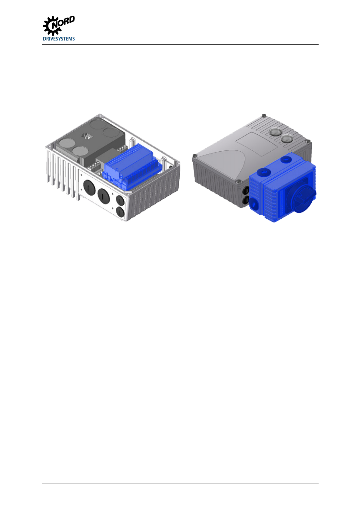
Option modules
Option modules are used to extend the functionality of the device.
These options are available as an installation variant, the so-called SK CU4-… customer unit, and also
as an attachment variant, the so-called SK TU4-… technology unit. As well as the mechanical
differences, the installation and attachment variants also have some functional differences.
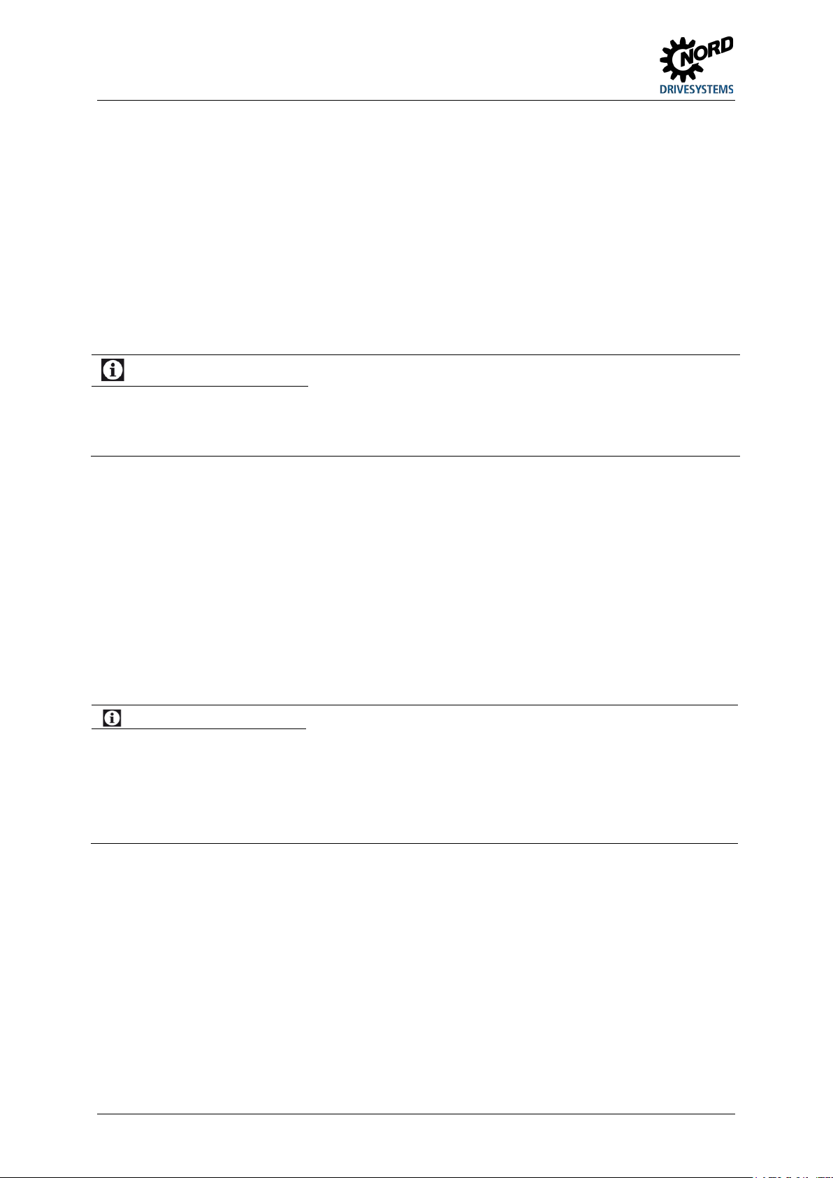
Figure 1: Device with internal SK CU4-... Figure 2: Device with external SK CU4-...
Attachment variant
The external technology unit (Technology Unit SK TU4-…) is externally attached to the device and
is therefore easy to access.
A technology unit basically requires the use of a suitable SK TI4-TU-… connection unit.
The power supply and signal lines are connected using the screw clamps of the connection unit.
Depending on the version, additional connections for connectors (e.g. M12 or RJ45) may be available.
The optional wall mounting kit SK TIE4-WMK-TU also allows the technology units to be mounted away
from the starter.
Built-in variant
The internal customer unit (Customer Unit, SK CU4-...) is integrated in the device. The power
supply and signal lines are connected using screw clamps.
BU 0135 en-4118 11
NORDAC START (SK 135E / SK 175E) – Users Manual for Motor Starters
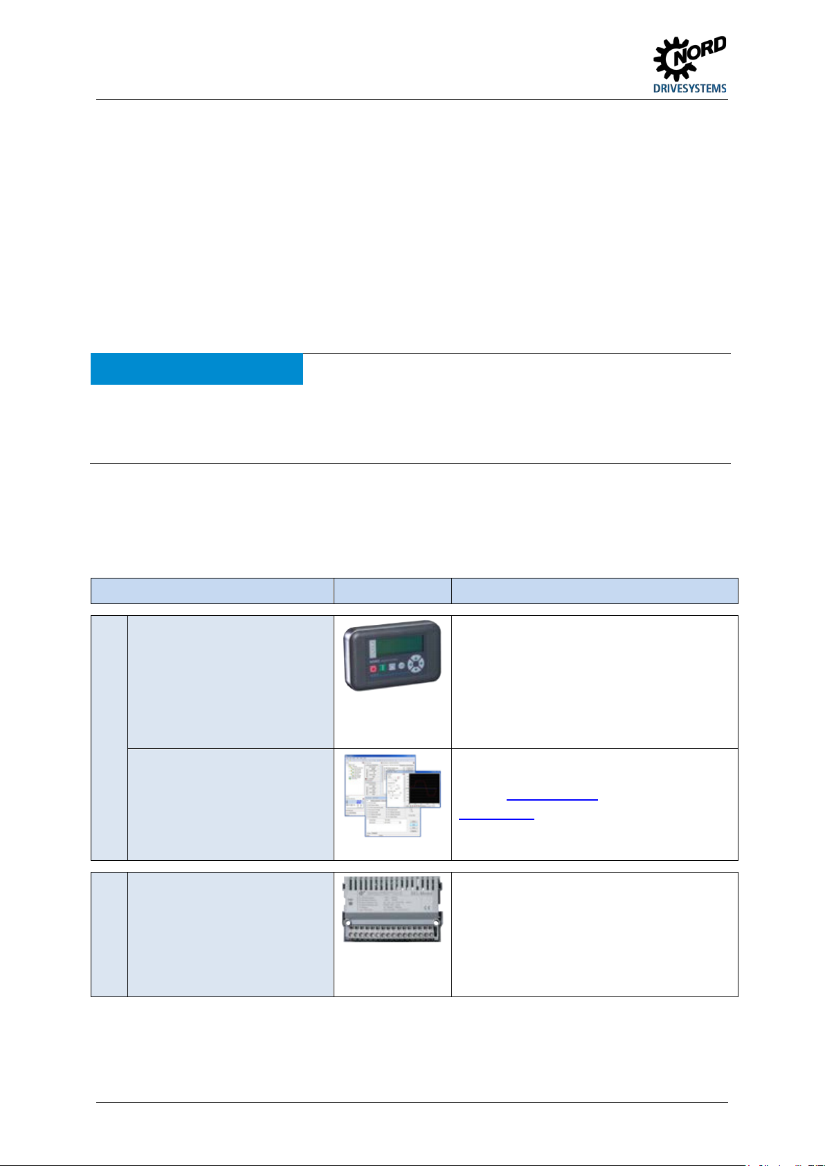
Control and parametrisation options
For commissioning, parametrisation and control
For commissioning, parametrisation and control
IO extension
Customer unit for installation in the device for
1.2 Delivery
Check the equipment immediately after delivery / unpacking for transport damage such as
deformation or loose parts.
If there is any damage, contact the carrier immediately and carry out a thorough assessment.
Important! This also applies even if the packaging is undamaged.
1.3 Scope of delivery
NOTICE Defect in the device
Use of unapproved accessories and options (e.g. options from other device series (SK CSX-0)) may result in
defects of the interconnected components.
Only use options and accessories which are explicitly intended for use with this device and are stated accordingly
in this manual.
Standard version: • IP55 version of device (optionally IP66, IP69K)
• Operating instructions as PDF file on CD ROM including NORD CON, (PC
parametrisation software)
Available accessories:
Designation Example Description
Parametrisation units for
temporary connection to the
device, handheld
Plus connection extension
SK TIE4-RS485-RS232 (Material number
275274603)
NORD CON
MS Windows ® - based
software
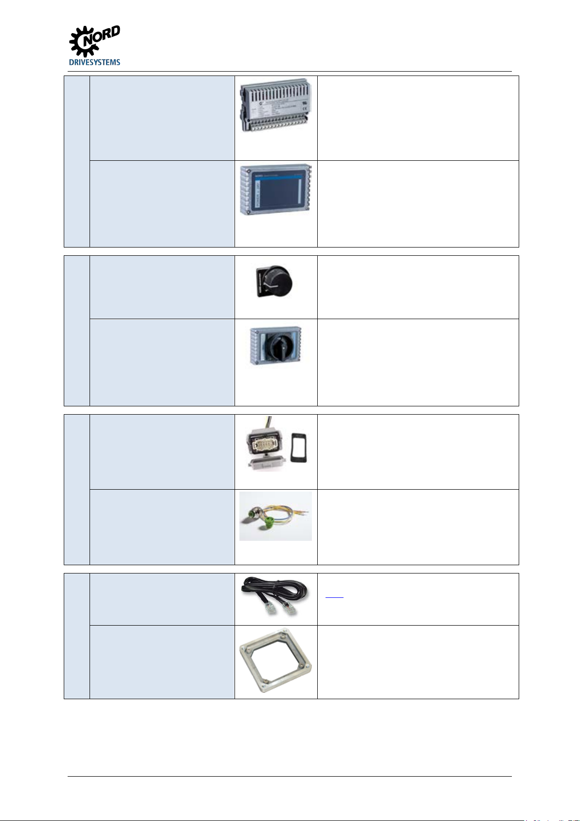
Internal signal converter
of the device.
Model SK PAR-3H, SK CSX-3H
( Paragraph 3.1 "Control and parametrisation
options ")
of the device.
Refer to www.nord.com
NORD CON
(Free download)
converting bipolar analogue signals to unipolar
analogue signals, e.g. digital signals on relays
Model SK CU4-REL- …
Section 3.2.1 "Internal customer interfaces
SK CU4-… (installation of modules)"
12 BU 0135 en-4118
1 General
Power supply for installation in the device for
Switch for attaching to the device for ease of
Plug connector
AC Power connector for attaching to the device
Different adapter cables
Various adapter kits for attaching the device to
Internal power supplies
External power supplies
Power supply
Switch
(L – OFF – R)
Maintenance switch
Switch
(0 – I)
Power connection
(for power input, power output,
motor output)
Control line connection
Adapter cable
generating the low control voltage (24 V DC).
Model SK CU4-24V- …
Section 3.2.1 "Internal customer interfaces
SK CU4-… (installation of modules)"
Technology unit for attaching to the device or
alternatively for wall mounting (wall mounting kit
required) for generating the low control voltage
(24 V DC).
Model SK TU4-24V- …
Section 3.2.2 "External technology units
SK TU4-… (module attachment)"
controlling the device
Model SK TIE4-SWT
Section 3.1 "Control and parametrisation
options "
Technology unit for attaching to the device or
alternatively for wall mounting (wall mounting kit
required) for reliably disconnecting the device
from the power supply.
Model SK TU4-MSW- …
Section 3.2.2 "External technology units
SK TU4-… (module attachment)"
for making a detachable connection for supply
lines (e.g. mains supply line)
Model SK TIE4-…
Section 3.2.3.1 "Plug connectors for power
connections"
System connector (M12) for attaching to the
device, for making a detachable connection for
control lines
Model SK TIE4-…
Section 3.2.3.2 "Plug connectors for control
connection"
(Link)
Mounting Adapter
Adapter
BU 0135 en-4118 13
different motor sizes
Section 2.1.1.1 "Adapters for different
motors"
NORDAC START (SK 135E / SK 175E) – Users Manual for Motor Starters
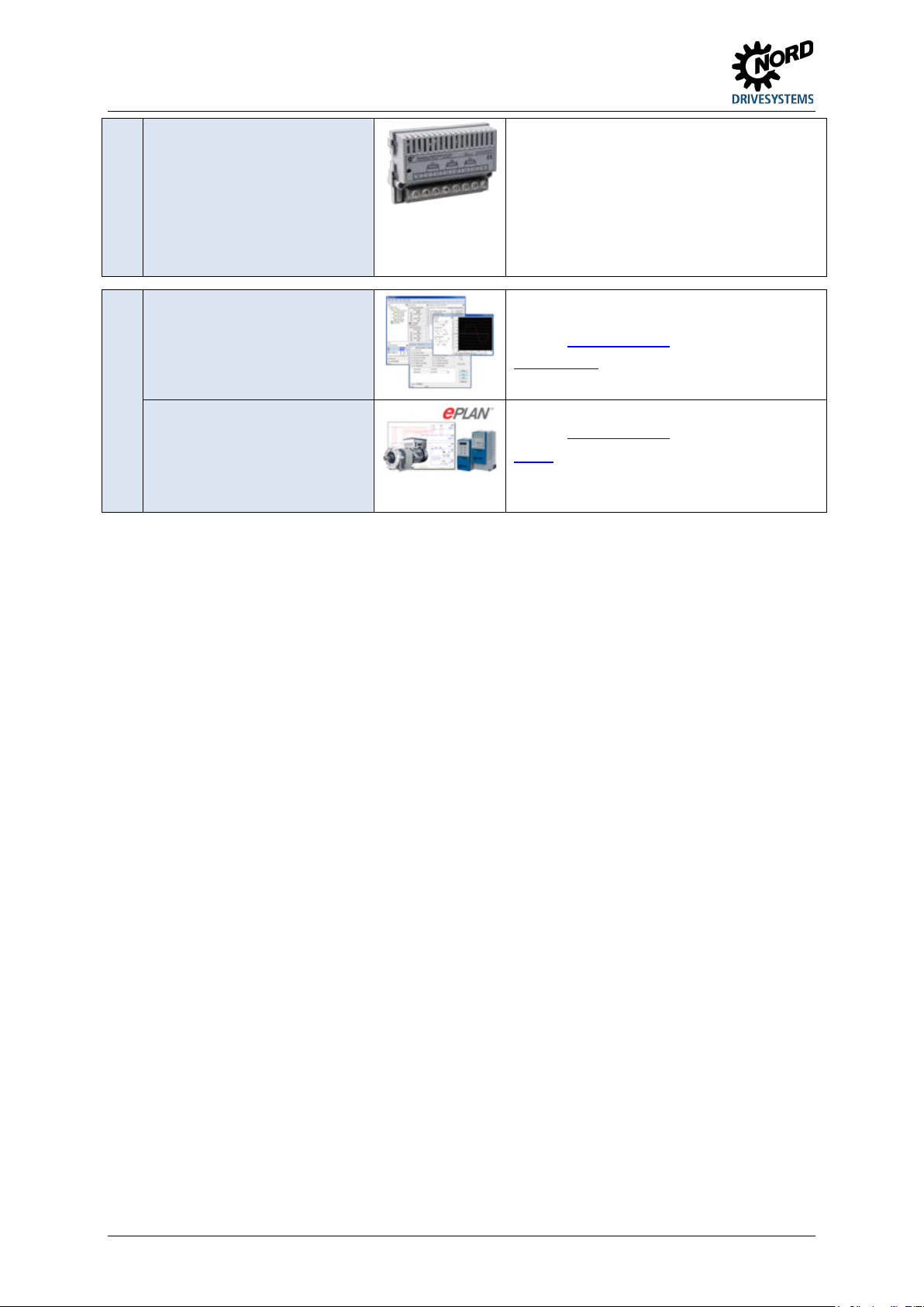
Miscellaneous
Customer unit for installation in the device, for
Software (Free download)
Macros for producing electrical circuit diagrams
Internal fuse module
protecting the individual device in the event of
"Daisy Chain" cabling (looping through of mains
voltage from one device to the next).
Model SK CU4-FUSE- …
Section 3.2.1 "Internal customer interfaces
SK CU4-… (installation of modules)"
NORD CON
MS Windows ® - based
software
For commissioning, parametrisation and control
of the device.
Refer to
www.nord.com
NORD CON
ePlan macros
Refer to www.nord.com
ePlan
14 BU 0135 en-4118

1 General
1.4 Safety, installation and operating instructions
Before working on or with the device, please read the following safety instructions extremely carefully.
Please pay attention to all other information from the device manual.
Non-compliance can result in serious or fatal injuries and damage to the device or its surroundings.
These safety instructions must be kept in a safe place!
1. General
Do not use defective devices or devices with defective or damaged housings or missing covers (e.g.
blind plugs for cable glands). Otherwise there is a risk of serious or fatal injuries caused by electric
shock or bursting electrical components such as powerful electrolytic capacitors.
Unauthorised removal of covers, improper use, incorrect installation or operation causes a risk of
serious personal injury or material damage.
During operation and depending on the protection class of the devices, there may be live, bare,
moving or rotating parts or hot surfaces.
The device operates with a dangerous voltage. Dangerous voltage may be present at the supply lines,
contact strips and PCBs of all connecting terminals (e.g. mains input, motor connection), even if the
device is not working or the motor is not rotating (e.g. caused by electronic disabling, jamming of the
drive or a short circuit at the output terminals).
The device is not equipped with a mains switch and is therefore always live when connected to the
power supply. Voltages may therefore be connected to a connected motor at standstill.
Even if the drive unit has been disconnected from the mains, a connected motor may rotate and
possibly generate a dangerous voltage.
If you come into contact with dangerous voltage such as this, there is a risk of an electric shock, which
can lead to serious or fatal injuries.
The device and any power plug connectors must not be disconnected while a voltage is applied to the
device. Failure to comply with this may cause arcing, which in addition to the risk of injury, also results
in a risk of damage or destruction of the device.
The fact that the status LED or other indicators are not illuminated does not indicate that the device
has been disconnected from the mains and is without voltage.
The heat sink and all other metal components can heat up to temperatures above 70 °C.
Touching these parts can result in local burns to the body parts concerned (cooling times and
clearance from neighbouring components must be complied with).
All work on the device, e.g. transportation, installation, commissioning and maintenance work must be
carried out by qualified experts (observe IEC 364 or CENELEC HD 384 or DIN VDE 0100 and
IEC 664 or DIN VDE 0110 and national accident prevention regulations). In particular, the general and
regional installation and safety regulations for work on high voltage systems (e.g. VDE) must be
complied with as must the regulations concerning correct use of tools and the use of personal
protection equipment.
During all work on the device, take care that no foreign bodies, loose parts, moisture or dust enter or
remain in the device (risk of short circuit, fire and corrosion).
Further information can be found in this documentation.
BU 0135 en-4118 15

NORDAC START (SK 135E / SK 175E) – Users Manual for Motor Starters
2. Qualified experts
For the purposes of these basic safety instructions, qualified personnel are persons who are familiar
with the assembly, installation, commissioning and operation of this product and who have the
relevant qualifications for their work.
Furthermore, the device and the associated accessories may only be installed and started up by
qualified electricians. An electrician is a person who, because of their technical training and
experience, has sufficient knowledge with regard to
• switching on, switching off, isolating, earthing and marking power circuits and devices,
• proper maintenance and use of protective devices in accordance with defined safety standards.
3. Correct purpose of use – general
The Motor starters are devices for industrial and commercial plants for operating three-phase
asynchronous motors with squirrel-cage rotors.
The devices are components intended for installation in electrical systems or machines.
Technical data and information for connection conditions can be found on the rating plate and in the
documentation, and must be complied with.
The devices may only be used for safety functions which are described and explicitly approved.
CE-labelled devices fulfil the requirements of the Low Voltage Directive 2014/35/EU. The stated
harmonized standards for the devices are used in the declaration of conformity.
a. Supplement: Correct purpose of use within the European Union
When installed in machines, the devices must not be commissioned (i.e. commencement of
proper use) until it has been ensured that the machine fulfils the provisions of EC Directive
2006/42/EC (Machinery Directive); EN 60204-1 must also be complied with.
Commissioning (i.e. start-up of proper use) is only permitted if the EMC directive (2014/30/EU)
has been complied with.
b. Supplement: Correct purpose of use outside the European Union
The local conditions of the operator for the installation and commissioning of the device must be
complied with at the usage location (see also "a) Supplement: Correct purpose of use within the
European Union").
4. Phases of life
Transport, storage
The information in the manual regarding transport, storage and correct handling must be complied
with.
The permissible mechanical and climatic ambient conditions (see technical data in the manual for the
device) must be complied with.
If necessary, suitable, adequately dimensioned means of transport (e.g. lifting gear, rope guides) must
be used.
16 BU 0135 en-4118

1 General
Installation and assembly
The installation and cooling of the device must be implemented according to the regulations in the
corresponding documentation. The permissible mechanical and climatic ambient conditions (see
technical data in the manual for the device) must be complied with.
The device must be protected against impermissible loads. In particular, components must not be
deformed and/or insulation distances must not be changed. Touching of electronic components and
contacts must be avoided.
The device and its optional modules contain electrostatically sensitive components, which can be
easily damaged by incorrect handling. Electrical components must not be mechanically damaged or
destroyed.
Electrical Connection
Ensure that the device and the motor are specified for the correct supply voltage.
Installation, maintenance and repair work must not be carried out unless the device has been
disconnected from the voltage and at least 5 minutes have elapsed since the mains was switched off!
(Due to charged capacitors, the equipment may continue to carry hazardous voltages for up to
5 minutes after being switched off at the mains). Before starting work it is essential to check by
measurement that all contacts of the power plug connections or the connection are voltage-free.
The electrical installation must be implemented as per the applicable regulations (e.g. cable crosssection, fuses, earth lead connections). Further instructions can be found in the documentation or
manual for the device.
Information regarding EMC-compliant installation such as shielding, earthing, location of filters and
routing of cables can be found in the documentation for the devices and in the technical information
manual TI 80-0011
. CE marked devices must also comply with these instructions. Compliance with the
limit values specified in the EMC regulations is the responsibility of the manufacturer of the system or
machine.
In case of a fault, insufficient earthing may cause an electric shock with possibly fatal consequences if
the device is touched.
The device may only be operated with effective earth connections which comply with local regulations
for large leakage currents (> 3.5 mA). Detailed information regarding connections and operating
conditions can be obtained from the technical Information manual TI 80-0019
.
The voltage supply of the device may directly or indirectly put it into operation, or touching electrically
conducting components may then cause an electric shock with possible fatal consequences.
All phases of all power connections (e.g. power supply) must always be disconnected.
Set-up, troubleshooting and commissioning
When working on live devices, the applicable national accident prevention regulations must be
complied with (e.g. BGV A3, formerly VBG 4).
The voltage supply of the device may directly or indirectly put it into operation, or touching electrically
conducting components may then cause an electric shock with possible fatal consequences.
The parametrisation and configuration of the devices must be selected so that no hazards can occur.
With certain setting conditions, the device or the motor which is connected to it may start automatically
when the mains are switched on. The machinery which it drives (press / chain hoist / roller / fan etc.)
may then make an unexpected movement. This may cause various injuries, including to third parties.
Before switching on the mains, secure the danger area by warning and removing all persons from the
danger area.
BU 0135 en-4118 17

NORDAC START (SK 135E / SK 175E) – Users Manual for Motor Starters
Operation
Where necessary, systems in which the devices are installed must be equipped with additional
monitoring and protective equipment according to the applicable safety requirements (e.g. legislation
concerning technical equipment, accident prevention regulations, etc.).
All covers must be kept closed during operation.
With certain setting conditions, the device or the motor which is connected to it may start automatically
when the mains are switched on. The machinery which it drives (press / chain hoist / roller / fan etc.)
may then make an unexpected movement. This may cause various injuries, including to third parties.
Before switching on the mains, secure the danger area by warning and removing all persons from the
danger area.
Maintenance, repair and decommissioning
Installation, maintenance and repair work must not be carried out unless the device has been
disconnected from the voltage and at least 5 minutes have elapsed since the mains was switched off!
(Due to charged capacitors, the equipment may continue to carry hazardous voltages for up to
5 minutes after being switched off at the mains). Before starting work it is essential to check by
measurement that all contacts of the power plug connections or the connection are voltage-free.
For further information, please refer to the manual for the device.
Disposal
The product and its parts and accessories must not be disposed of as domestic waste. At the end of
its life, the product must be properly disposed of according to the local regulations for industrial waste.
In particular, this product contains integrated semiconductor circuits (PCBs and various electronic
components, including high power capacitors). In case of incorrect disposal there is a risk of formation
of toxic gases, which may cause contamination of the environment and direct or indirect injuries (e.g.
chemical burns). In the case of high power capacitors, there is also a risk of explosion, with the
associated risk of injury.
5. Potentially explosive environment (ATEX, EAC Ex)
In order to operate or carry out installation work in potentially explosive environments (ATEX,
EAC Ex), the device must be approved and the relevant requirements and notes from the manual of
the device must be complied with.
Failure to comply can result in the ignition of an explosive atmosphere and fatal injuries.
• Only persons who are qualified, i.e. trained and authorised for all assembly, service,
commissioning and operation work on association with explosion hazard environments may work
with the devices described here (including the motors, geared motors, any accessories and all
connection technology).
• Explosive concentrations of dust may cause explosions if ignited by hot or sparking objects. Such
explosions may cause serious or fatal injuries to persons or severe material damage.
18 BU 0135 en-4118

1 General
• The drive must comply with the specifications of "Planning guideline for the operating and
installation instructions B1091" B1091-1
• Only original parts which are approved for the device and for operation in an explosion hazard area
ATEX Zone 22 3D, EAC Ex must be used.
• Repairs may only be carried out by Getriebebau NORD GmbH & Co. KG.
.
BU 0135 en-4118 19
NORDAC START (SK 135E / SK 175E) – Users Manual for Motor Starters
Danger
Electric shock
CAUTION
Hot surfaces
NOTICE
EDS
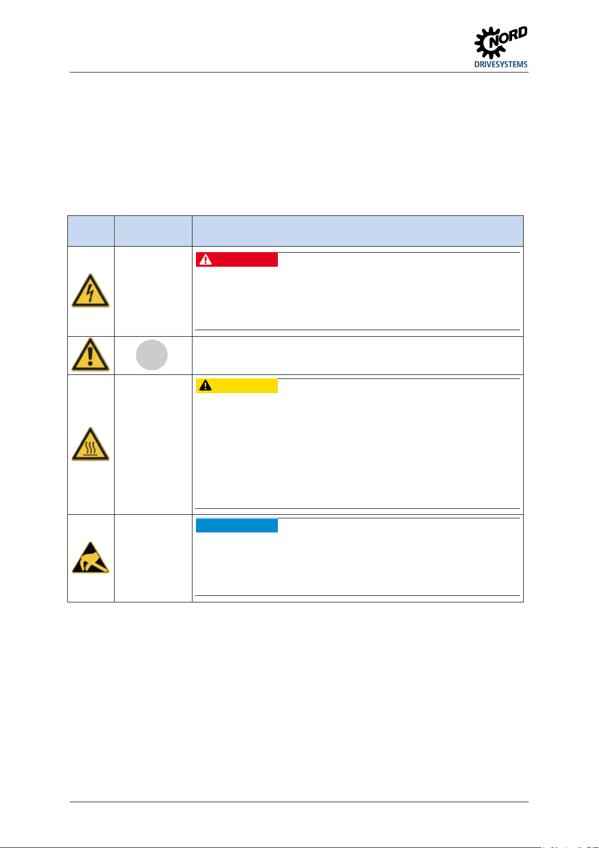
1.5 Warning and hazard information
Under certain circumstances, hazardous situations may occur in association with the frequency
inverter. In order to give explicit warning of possibly hazardous situations, clear warning and hazard
information can be found on the device and in the relevant documentation.
1.5.1 Warning and hazard information on the product
The following warning and hazard information is used on the product.
Symbol
Supplement to
symbol 1)
DANGER
Device is live
> 5min after
removing mains
voltage
Meaning
The device contains powerful capacitors. Because of this, there may be a
hazardous voltage for more than 5 minutes after disconnection from the mains.
Before starting work, check that the device is free of voltage at all power
contacts by means of suitable measuring equipment.
It is essential to read the manual in order to prevent hazards!
The heat sink and all other metal components as well as the surfaces of plug
connectors may heat up to temperatures in excess of 70°C.
• Danger of injury due to local burns on contact.
• Heat damage to adjacent objects
Allow sufficient cooling time before starting work on the device. Check the
surface temperatures with suitable measuring equipment. Maintain an
adequate distance to adjacent components or provide protection against
contact.
The device contains electrostatically sensitive components, which can be
easily damaged by incorrect handling.
Avoid all contact (indirect contact by tools or similar, or direct contact) with
PCBs and their components.
1) Texts are written in English.
Table 3: Warning and hazard information on the product
20 BU 0135 en-4118
1 General
Low Voltage
UL 60947-1
1.5.2 Warning and hazard information in the document
The warning and hazard information in this document are located at the beginning of the section which
describes the action which may result in the corresponding hazards.
The warning and hazard information is classified as follows according to the risk and the severity of
the resulting injuries.
DANGER!
WARNING
CAUTION
NOTICE
Indicates an immediate danger, which may result in death or serious injury.
Indicates a possibly dangerous situation, which may result in death or
serious injury.
Indicates a possibly dangerous situation, which may result in slight or
minor injuries.
Indicates a possibly harmful situation, which may cause damage to the
product or the environment.
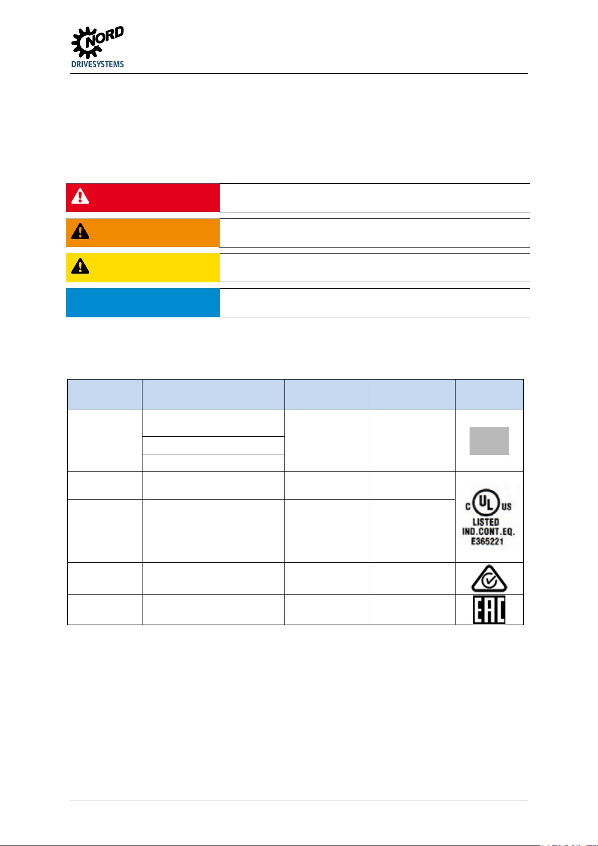
1.6 Standards and approvals
All devices of the entire SK 200E series comply with the standards and directives listed below.
Approval Directive
CE
(European
Union)
Directive
EMC 2014/30/EU
RoHS 2011/65/EU
UL
(USA)
CSA
(Canada)
2014/35/EU
Applied
standards
EN 60947-1
EN 60529
EN 60947-4-2
EN 50581
UL 60947-4-2
C22.2
No.UL 60947-1-13
C22.2
No.UL 60947-4-214
Certificates Code
C310800
E365221
E365221
C-Tick
(Australia)
EAC
(Eurasia)
Table 4: Standards and approvals
N 23134
TR CU 004/2011,
TR CU 020/2011
IEC 60947-1
IEC 60947-4-2
TC RU CDE.AЛ32.B.01859
BU 0135 en-4118 21
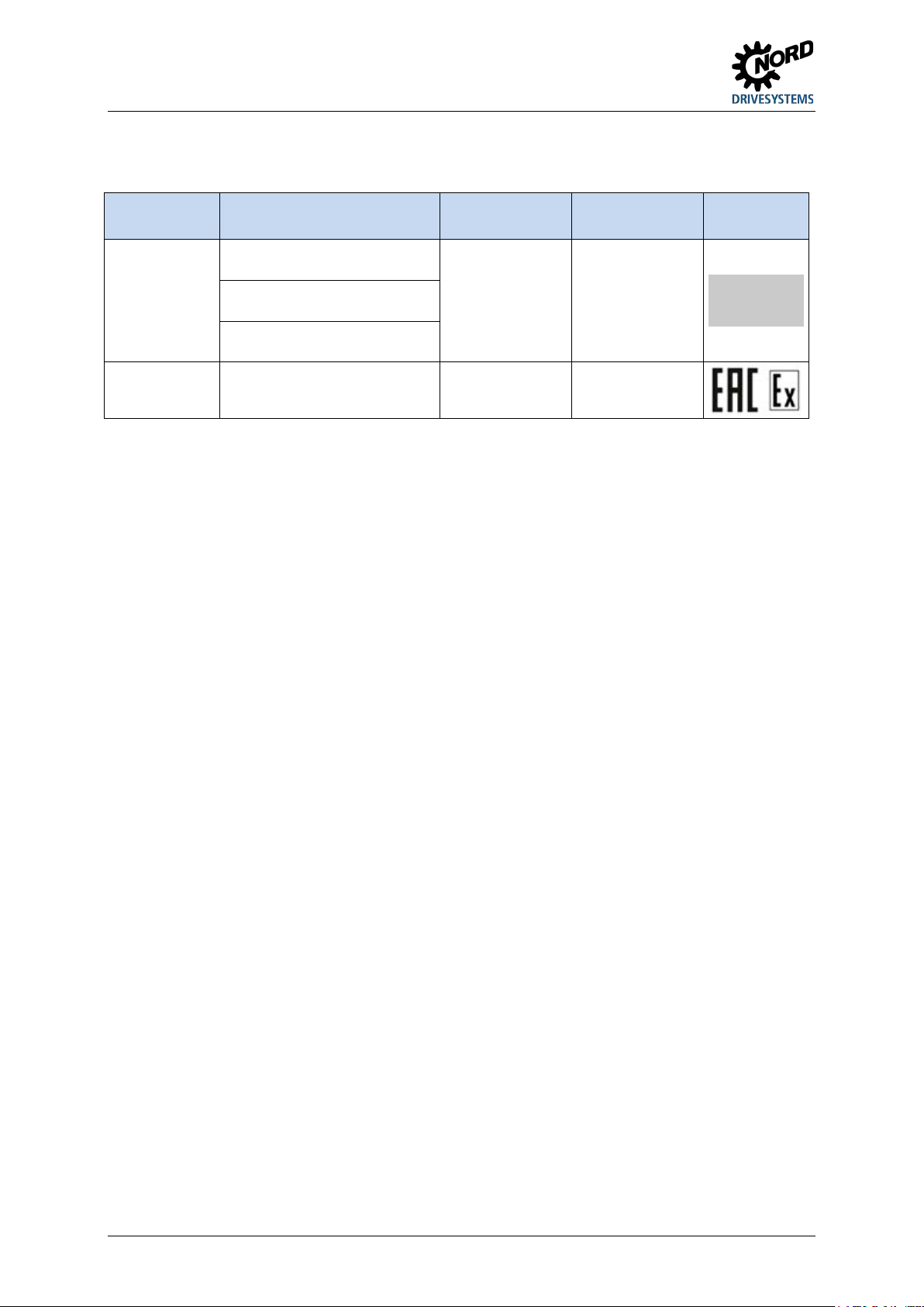
NORDAC START (SK 135E / SK 175E) – Users Manual for Motor Starters
Devices which are configured and approved for use in explosion hazard environments ( Section 2.4
"Operation in potentially explosive environments ") comply with the following directives and standards.
Approval Directive
ATEX 2014/34/EU
ATEX
(European
EMC 2014/30/EU
Union)
RoHS 2011/65/EU
EAC Ex
(Eurasia)
Table 5: Standards and approvals for explosion hazard environments
TR CU 012/2011
Applied
standards
EN 60079-0
EN 60079-31
EN 61800-5-1
EN 60529
EN 61800-3
EN 50581
IEC 60079-0
IEC 60079-31
Certificates Code
C432810
TC RU CDE.AA87.B.01108
22 BU 0135 en-4118
1 General
Information
Group fuse protection
1.6.1 UL and CSA approval
File No. E365221
Categorisation of protective devices approved by the UL according to United States Standards for the
inverters described in this manual is listed below with essentially the original wording. The
categorisation of individually relevant fuses or circuit breakers can be found in this manual under the
heading “Electrical Data”. All devices include motor overload protection.
( section 7.2 "Electrical data")
The devices can basically be protected as a group via a common fuse (details in the following). The adherence of
the total currents and the use of the correct cables and cable cross-sections must be taken into account when
doing this. If the device or devices is/are being installed close to the motor, this also applies to the motor cable.
UL / CSA conditions according to the report
Information
“Use 60/75°C copper field wiring conductors.”
„These products are intended for use in a pollution degree 2 environment“
“The device has to be mounted according to the manufacturer instructions.”
BU 0135 en-4118 23
NORDAC START (SK 135E / SK 175E) – Users Manual for Motor Starters
Interrupting Capacity, Current
Motor group
Size valid description
1 - 2 generally valid “Suitable For Use On A Circuit Capable Of Delivering Not More Than 100 000 rms Symmetrical
installation
(Group fusing):
differing data
CSA:
1)
( 7.2)
Amperes, 500 Volts Maximum” “When Protected by class RK5 Fuses or faster, rated ______
Amperes, and 500 Volts”, as listed in
1)
.
“Suitable For Use On A Circuit Capable Of Delivering Not More Than 100 000 rms Symmetrical
Amperes, 500 Volts Maximum” “When Protected by HighLimiting Class CC, G, J, L, R, T, etc., as listed in 1).
“Suitable For Use On A Circuit Capable Of Delivering Not More Than 65 000 rms Symmetrical
Amperes, 480 Volt maximum”,
“When Protected by Circuit Breaker (inverse time trip type) in accordance with UL 489, rated
______ Amperes, and 480 Volts”, as listed in
1)
, Rated short circuit current min. 65 kA
"Suitable For Use On A Circuit Capable Of Delivering Not More Than 100 000 rms Symmetrical
Amperes, 500 Volts Max., When Protected by internal device SK CU4-FUSE”
“Suitable for motor group installation on a circuit capable of delivering not more than 100 000
rms symmetrical amperes, 500 V max” “When Protected by class RK5 Fuses or faster, rated
30_Amperes and 500 Volts.”
“Suitable for motor group installation on a circuit capable of delivering not more than 100 000
rms symmetrical amperes, 500 V max” “When Protected by High-Interrupting Capacity, Current
Limiting Class CC, G, J, L, R, T, etc. Fuses rated 30 Amperes”
“Suitable for motor group installation on a circuit capable of delivering not more than 65 000
rms symmetrical amperes, 480 V max” “When Protected by Circuit Breaker (inverse time trip
type) in accordance with UL 489, rated 30 Amperes and 500 Volts, 480 V min”
None differing data equal to UL
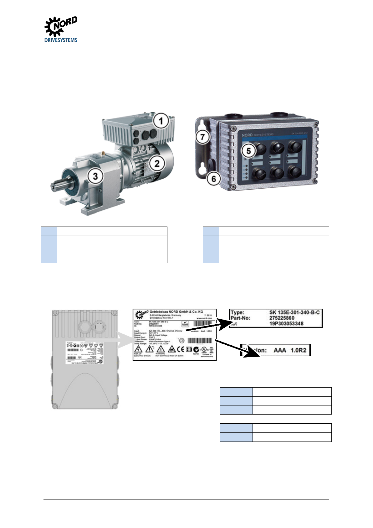
24 BU 0135 en-4118
1 General
1
Motor starters
5 Optional module
2
6
3
Gear units
7 Wall-mounting kit
Legend
Type:
Type / designation
ID:
Device ident number
FW:
Firmware version (x.x Rx)
HW:
Hardware version (xxx)
1.7 Type code / nomenclature
Unique type codes have been defined for the individual modules and devices. These provide
individual details of the device type and its electrical data, protection class, fixing version and special
versions. A differentiation is made according to the following groups:
Motor
Connection unit
1.7.1 Name plate
All of the information which is relevant for the device, including information for the identification of the
device can be obtained from the type plate.
Part No.: Part Number
Figure 3: Name plate
BU 0135 en-4118 25
NORDAC START (SK 135E / SK 175E) – Users Manual for Motor Starters
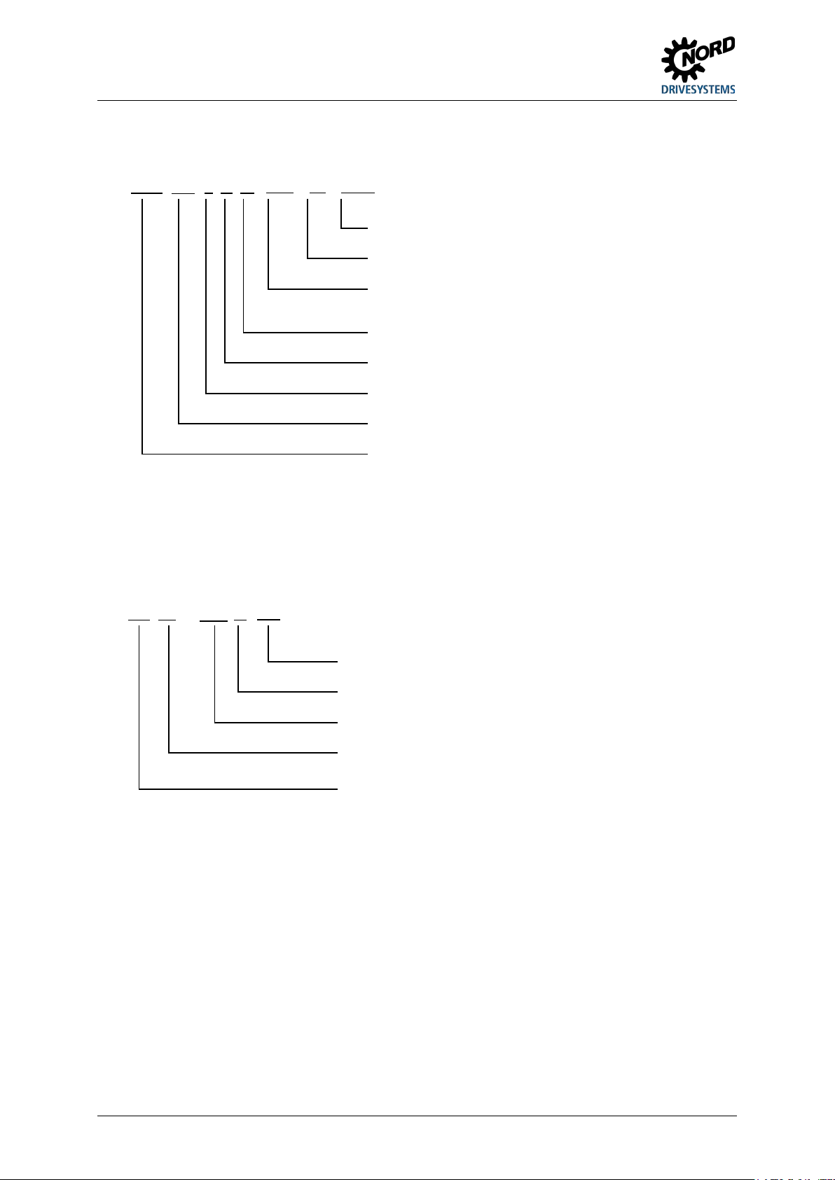
Special version
IP protection class: Standard = IP55, C = IP66, C-NSD = IP69K
Device version: ASI – integrated AS Interface, PBR –
Radio interference filter: O = none, B= Class B
Mains voltage: x40 = 200 - 500 V
Number of mains phases: 3xx = 3-phase
Device rated power: 301 = 3.0 kW, 751 = 7.5 kW
Device series:
SK 135E, SK 175E
(...) Options, only implemented if required.
Radio interference filter: B = Class B (C1)
Mains connection: 123 = 1~ 230V, 140 = 1~ 400V
Option series:
TU4 = external technology unit (attachment),
(...) Options, only implemented if required.
1.7.2 Type code Motor starter
SK 175E-751-340-B (-ASI) (-C) (-xxx)
integrated PROFIBUS DP
1.7.3 Type code for option modules
For "PotiBox" power supply or potentiometer modules
SK TU4-24V-123-B (-C)
IP protection class: Standard = IP55, C = "coated" = IP66
Option type: 24V = 24V power supply, POT = Potentiometer/switch
module
CU4 = internal customer unit (installation)
26 BU 0135 en-4118
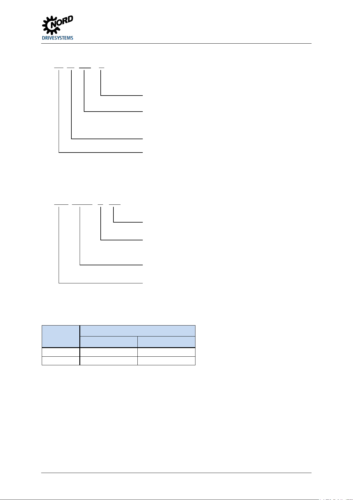
1 General
IP protection class: Standard = IP55, C = "coated" IP66
Suitable
NET = Mains option module (e.g. TU4-24V-…)
Group: TU = Technology unit
Device series: SK TI4 = Connection unit SK TI4
(...) Options, only implemented if required.
Further details (depending on type)
Details (depending
C = IP66, EX = ATEX, PBR = PROFIBUS –
Connection extension
Size 2
2.2 ... 4.0 kW
4.0 ... 7.5 kW
The sizes that have been mentioned differ from each other in terms of
1.7.4 Type code, connection unit for technology unit
SK TI4-TU-BUS (-C)
1.7.5 Adapter Unit type code
SK TIE4-WMK-1 (-C- …)
device types:
BUS = Bus option module (e.g. CANopen:
TU4-CAO
on type)
Type (selection): WMK-1 = Wall mounting kit (version 1),
M12 = M12 plug connector for connection of signal cables,
HAN = Harting – System plug connector for power connection
1.8 Power rating / Motor size
Size 1)
Size 1 0.12 ... 1.5 kW 0.25 ... 3.0 kW
1)
the envelope dimensions. The difference is restricted to the version of
the opening for fitting the terminal box to a motor.
Mains / power assignment
3~ 200 – 240 V 3~ 380 – 500 V
Signal cable, …
BU 0135 en-4118 27
NORDAC START (SK 135E / SK 175E) – Users Manual for Motor Starters
Information
IP66 special measures
1.9 Version in protection class IP55, IP66, IP69K
The SK 1x5E is available in IP55 (standard) or IP66, IP69K (optional). The additional modules are
available in protection classes IP55 (standard) or IP66 (optional).
A protection class that differs from the standard (IP66, IP69K) must always be specified in the order
when ordering!
There are no restrictions or differences to the scope of functionality in the protection classes that have
been mentioned. The type designation is extended accordingly in order to distinguish between the
protection classes.
e.g. SK 1x5E-221-340-A-C
Information
Cable laying
For all versions, care must be taken that the cables and the cable glands at least comply with the protection class
of the device and the attachment regulations and are carefully matched. The cables must be inserted so that
water is deflected away from the device (if necessary use loops). This is essential to ensure that the required
protection class is maintained.
IP55 version:
The IP55 version is the standard version. In this version, the two installation types motor mounted
(fitted onto the motor) and close coupled (fitted to the wall bracket) are available. All adapter units,
technology units and customer units are also available for this version.
IP66 version:
The IP66 version is a modified option of the IP55 version. Both installation types (motor-integrated,
close coupled) are also available for this version. The modules available to the IP66 design (adapter
units, technology units and customer units) have the same functionalities as the corresponding IP55
design modules.
The modules for the IP66 version are identified by an additional "-C" in the type key, and are modified with the
following special measures:
• impregnated PCBs,
• Powder coating RAL 9006 (white aluminium) for housing,
• modified blank screw caps (UV-resistant),
• Low pressure test.
IP69K version:
The IP69K version is a modified option of the IP66 version. In device with protection class IP69K, the
housing is made from nsd-tupH. Both installation types (motor-integrated, close coupled) are also
available for this version.
Additional attachments (technology units etc.) to the device are not permitted.
28 BU 0135 en-4118
2 Assembly and installation
Information
Device version IP6x
2 Assembly and installation
2.1 Installation SK 1x5E
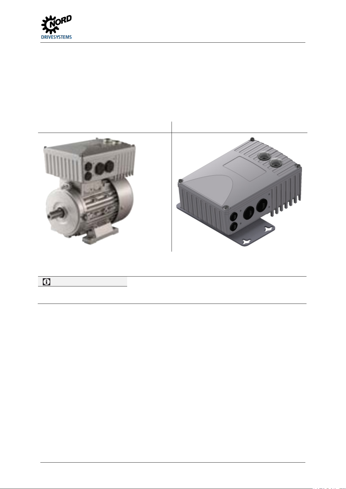
The devices are available in various sizes depending on their output. They can be mounted on the
terminal box of a motor or in its immediate vicinity.
Motor-mounted version Wall-mounted version
When a complete drive unit (gear unit + motor + SK 1x5E) is delivered, the device is always fully
installed and tested.
IP6x-compliant devices must be installed by NORD, since special measures have to be implemented. IP6x
components that are retrofitted on site cannot ensure that this protection class is provided.
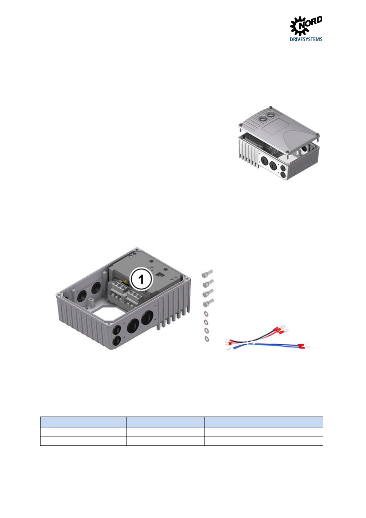
When delivered separately, the device includes the following components:
• SK 1x5E
• Screws and contact washers for mounting the motor terminal box
• Pre-fabricated cable for motor and PTC connections
The sizes of the device series only differ with regard to their possibilities for adapting to the matching
motors. For example, size 1 is coordinated with motor sizes 80 – 100, and size 2 is coordinated with
motor size 132. The external dimensions (envelope dimensions) of the devices are identical.
BU 0135 en-4118 29
NORDAC START (SK 135E / SK 175E) – Users Manual for Motor Starters
1.
If necessary, remove the original terminal box from the NORD motor, so that only the base of the terminal
. To do this, undo 4
fastening screws and then remove the casing cover vertically from
6.
Re-attach the casing cover. In order to ensure that the protection class for the device is achieved, care must
Size 1
M5 x 25
3.5 Nm ± 20 %
2.1.1 Work procedures for motor installation
box and the motor terminal strip remain.
2. Set the bridges for the correct motor circuit at the motor terminal strip, and connect the pre-fabricated
cables for motor and PTC connections to the respective connection points on the motor.
Remove the casing cover from the SK 1x5E
3.
above.
4. Fit the casing of the SK 1x5E to the terminal box base of the NORD motor using the existing screws and
seal as well as the provided toothed contact washers. When doing this, align the casing so that the rounded
side is facing the direction of the A bearing cover of the motor. Carry out mechanical adaptation using the
"Adapter kit" ( Section 2.1.1.1 "Adapters for different motors"). With motors made by other manufacturers,
it must be checked whether they can be attached.
If necessary, the plastic cover (1) for the electronics must be carefully removed in order to make the screw
fastenings to the base of the terminal box. Proceed with extreme caution when doing this to avoid damage
to the exposed PCBs.
5. Make electrical connections. For the cable gland of the connecting cable, appropriate screwed connections
for cable cross-section must be used.
be taken that all the fastening screws of the housing cover are tightened crosswise, gradually and with the
torque specified in the table below.
The cable glands that are used must at least correspond to the protection class of the device.
Size SK 1x5E Screw size Tightening torque
Size 2 M5 x 25 3.5 Nm ± 20 %
30 BU 0135 en-4118
 Loading...