

Page 1
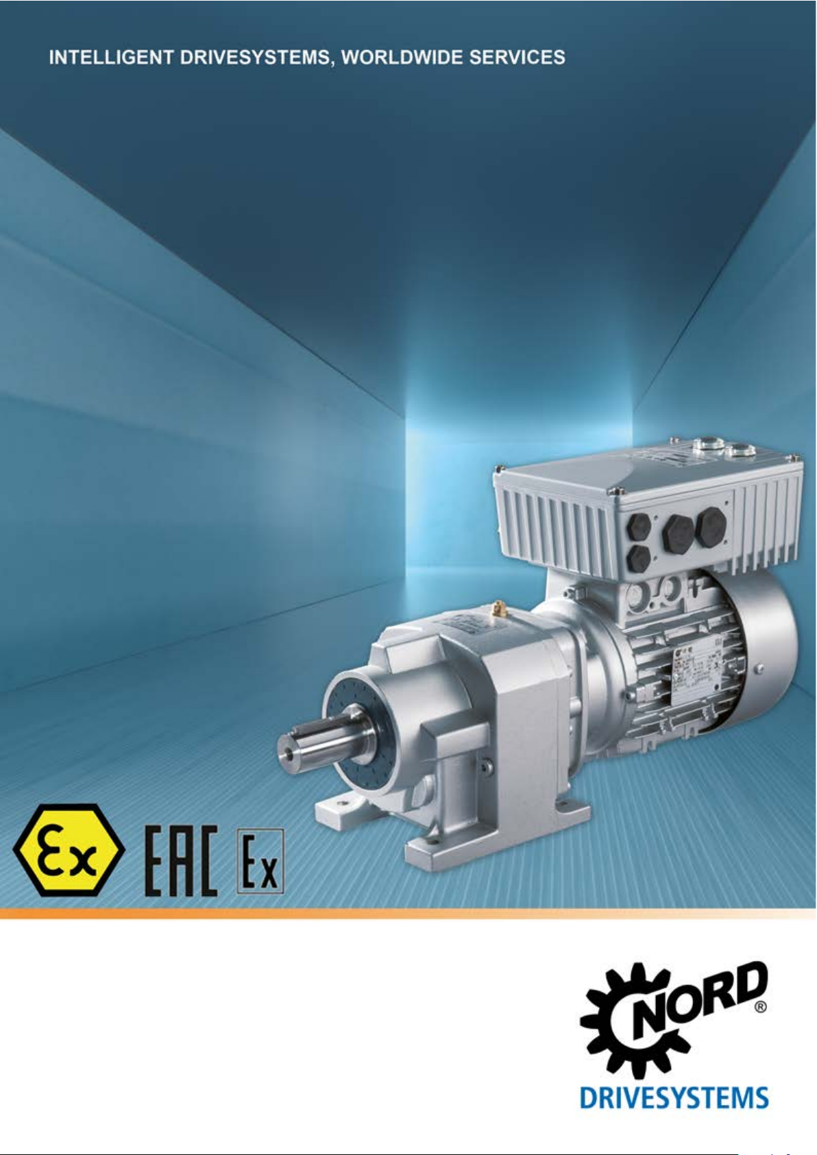
BU 0135 – en
NORDAC® START (SK 135E / SK 175E)
Users Manual for Motor Starters
Page 2
NORDAC START (SK 135E / SK 175E) – Users Manual for Motor Starters
Title:
BU 0135
Order – No.:
6071302
Series:
SK 1x5E
Device series:
SK 135E, SK 175E
BU 0135,
6071302 / 3415
V 1.0 R2
BU 0135
6071302
Documentation
Device types: SK 1x5E-301-340-A
SK 1x5E-751-340-A
Version list
Title,
Date
BU 0135,
July 2013
August 2015
BU 0135,
February
2016
,
March 2016
Order number Device
software
version
6071302 / 2713 V 1.0 R0 First issue.
Including:
• General corrections
• Cover contains additional diagnostics socket
• Adaptations of various parameters
• Adaptations of various error messages
• New presentation of scope of delivery / accessory
overview
• Revision of chapter "UL and cUL Approval"
• Adaptations in the "Technical / Electrical Data“
6071302 / 0616 V 1.0 R2
Including:
• General corrections
• Structural adjustments to document
• AS interface section
• Display and control section
• EMC section
• Description of power supplies removed
/ 1216 V 1.0 R3
• Correction to parameter P108
• Assignment of ATEX kits
• Updating of EC/EU conformity declarations
Remarks
Table 1: Version list
2 BU 0135 en-4118
BU 0135,
October
2018
6071302 / 4118 V 1.1 R0
Including:
• General corrections
• Revision of safety information
• Revision of warning information
• Adaptations to ATEX and outdoor installation
• Addition of EAC EX
• Revision of wall mounting kits and adapter kits for
motor mounting
• Adaptation of parameters: P001, 130, 434
• Addition of parameter P780
• Updating of EC/EU conformity declarations
• Correction of diagrams for switch-off mode 1-4
Page 3

Copyright notice
Copyright notice
As an integral component of the device described here, this document must be provided to all
users in a suitable form.
Any editing or amendment or other utilisation of the document is prohibited.
Publisher
Getriebebau NORD GmbH & Co. KG
Getriebebau-Nord-Straße 1 • 22941 Bargteheide, Germany • http://www.nord.com/
Fon +49 (0) 45 32 / 289-0 • Fax +49 (0) 45 32 / 289-2253
Member of the NORD DRIVESYSTEMS Group
BU 0135 en-4118 3
Page 4

NORDAC START (SK 135E / SK 175E) – Users Manual for Motor Starters
4 BU 0135 en-4118
Page 5

Table of Contents
Table of Contents
1 General ......................................................................................................................................................... 9
1.1 Overview ............................................................................................................................................ 9
1.2 Delivery ............................................................................................................................................ 12
1.3 Scope of delivery.............................................................................................................................. 12
1.4 Safety, installation and operating instructions .................................................................................. 15
1.5 Warning and hazard information ...................................................................................................... 20
1.5.1 Warning and hazard information on the product ................................................................. 20
1.5.2 Warning and hazard information in the document .............................................................. 21
1.6 Standards and approvals ................................................................................................................. 21
1.6.1 UL and CSA approval ......................................................................................................... 23
1.7 Type code / nomenclature ................................................................................................................ 25
1.7.1 Name plate ......................................................................................................................... 25
1.7.2 Type code Motor starter ..................................................................................................... 26
1.7.3 Type code for option modules ............................................................................................ 26
1.7.4 Type code, connection unit for technology unit................................................................... 27
1.7.5 Adapter Unit type code ....................................................................................................... 27
1.8 Power rating / Motor size ................................................................................................................. 27
1.9 Version in protection class IP55, IP66, IP69K .................................................................................. 28
2 Assembly and installation ........................................................................................................................ 29
2.1 Installation SK 1x5E ......................................................................................................................... 29
2.1.1 Work procedures for motor installation ............................................................................... 30
2.1.1.1 Adapters for different motors 31
2.1.1.2 Dimensions, SK 1x5E mounted on motor 32
2.1.2 Wall mounting ..................................................................................................................... 33
2.2 Installation of optional modules ........................................................................................................ 35
2.2.1 Option locations on the device............................................................................................ 35
2.2.2 Installation of internal customer unit SK CU4-… (installation) ............................................ 36
2.2.3 Installation of external technology units SK TU4-… (attachment) ....................................... 37
2.3 Electrical Connection ....................................................................................................................... 38
2.3.1 Wiring guidelines ................................................................................................................ 39
2.3.2 Electrical connection of power unit ..................................................................................... 40
2.3.2.1 Mains supply (L1, L2, L3, PE) 40
2.3.2.2 Motor cable (U, V, W, PE) 41
2.3.2.3 Electromechanical brake 41
2.3.3 Electrical connection of the control unit .............................................................................. 42
2.3.3.1 Control terminal details 43
2.3.3.2 Power supply SK xU4-24V-… - Connection example 46
2.4 Operation in potentially explosive environments .............................................................................. 47
2.4.1 Operation in potentially explosive environments - ATEX zone 22 3D ................................. 48
2.4.1.1 Modification of the device for compliance with Category 3D 48
2.4.1.2 Options for ATEX Zone 22, category 3D 48
2.4.1.3 Commissioning information 49
2.4.1.4 EU conformity declaration - ATEX 50
2.4.2 Operation in potentially explosive environments - EAC Ex ................................................. 51
2.4.2.1 Modification of the device 51
2.4.2.2 Further Information 52
2.4.2.3 EAC Ex certificate 52
2.5 Outdoor installation .......................................................................................................................... 53
3 Display, operation and options ................................................................................................................ 54
3.1 Control and parametrisation options ................................................................................................ 54
3.1.1 Control and parametrisation units, use ............................................................................... 55
3.2 Optional modules ............................................................................................................................. 57
3.2.1 Internal customer interfaces SK CU4-… (installation of modules) ...................................... 57
3.2.2 External technology units SK TU4-… (module attachment) ............................................... 58
3.2.3 plug connectors .................................................................................................................. 59
3.2.3.1 Plug connectors for power connections 59
3.2.3.2 Plug connectors for control connection 60
4 Commissioning ......................................................................................................................................... 62
BU 0135 en-4118 5
Page 6

NORDAC START (SK 135E / SK 175E) – Users Manual for Motor Starters
4.1 Factory settings ................................................................................................................................ 62
4.2 Starting up the device ...................................................................................................................... 62
4.2.1 Connection ......................................................................................................................... 63
4.2.2 Configuration ...................................................................................................................... 63
4.2.2.1 Parametrisation 64
4.2.2.2 Potentiometers P1 to P4 65
4.2.2.3 DIP switches (S1) 66
4.2.2.4 Overview of switch-off modes 66
4.2.3 Commissioning examples ................................................................................................... 68
4.3 AS Interface (AS-i) ........................................................................................................................... 69
4.3.1 The bus system .................................................................................................................. 69
4.3.2 Features and technical data ............................................................................................... 69
4.3.3 Bus structure and topology ................................................................................................. 70
4.3.4 Commissioning ................................................................................................................... 72
4.3.4.1 Connection 72
4.3.4.2 Displays 73
4.3.4.3 Configuration 73
4.3.4.4 Addressing 74
4.3.5 Certificate ........................................................................................................................... 75
4.4 PROFIBUS DP ................................................................................................................................. 76
4.4.1 The bus system .................................................................................................................. 76
4.4.2 Features ............................................................................................................................. 76
4.4.3 Commissioning ................................................................................................................... 77
4.4.3.1 Connection 77
4.4.3.2 Displays 77
4.4.3.3 Configuration 78
4.4.3.4 Addressing 79
5 Parameter ................................................................................................................................................... 80
5.1 Parameter overview ......................................................................................................................... 81
5.2 Description of parameters ................................................................................................................ 82
5.2.1 Operating displays .............................................................................................................. 84
5.2.2 Basic parameters ................................................................................................................ 85
5.2.3 Motor data .......................................................................................................................... 87
5.2.4 Control terminals ................................................................................................................ 88
5.2.5 Additional parameters ......................................................................................................... 92
5.2.6 Information.......................................................................................................................... 95
6 Operating status messages ................................................................................................................... 100
6.1 Display of messages ...................................................................................................................... 100
6.2 Diagnostic LEDs on device ............................................................................................................ 101
6.3 Messages ....................................................................................................................................... 102
6.4 FAQ operational problems ............................................................................................................. 104
7 Technical data ......................................................................................................................................... 105
7.1 General data Motor starter ............................................................................................................. 105
7.2 Electrical data ................................................................................................................................ 106
7.2.1 Electrical data ................................................................................................................... 107
8 Additional information ............................................................................................................................ 108
8.1 Electromagnetic compatibility (EMC) ............................................................................................. 108
8.1.1 General Provisions ........................................................................................................... 108
8.1.2 EMC evaluation - EN 55011-1 (environmental standard) ................................................. 108
8.1.3 EMC of device .................................................................................................................. 109
8.1.4 EU Declaration of Conformity ........................................................................................... 111
8.2 Operation on the FI circuit breaker ................................................................................................. 112
9 Maintenance and servicing information ................................................................................................ 113
9.1 Maintenance Instructions ............................................................................................................... 113
9.2 Service notes ................................................................................................................................. 114
9.3 Abbreviations ................................................................................................................................. 115
6 BU 0135 en-4118
Page 7

List of illustrations
List of illustrations
Figure 1: Device with internal SK CU4-... .............................................................................................................. 11
Figure 2: Device with external SK CU4-... ............................................................................................................. 11
Figure 3: Name plate ............................................................................................................................................. 25
Figure 4: Example of motor size adaptation .......................................................................................................... 31
Figure 5: Option locations ...................................................................................................................................... 35
Figure 6: Connection example, power supply SK xU4-24V-… .............................................................................. 46
Figure 7: SK CSX-3H / SK PAR-3H / SK TIE4-RS485-RS232 (l-r) ........................................................................ 55
Figure 8: internal customer units SK CU4 … example .......................................................................................... 57
Figure 9: external technology units SK TU4-… (example) ..................................................................................... 58
Figure 10: Examples of devices with connectors for connecting the power ........................................................... 59
Figure 11: AS-i, connecting terminals and jumper position (example of "AUX" position) ....................................... 72
Figure 12: PROFIBUS, connecting terminals and jumper position (example of "OFF" position) ........................... 77
Figure 13: Explanation of parameter description ................................................................................................... 82
BU 0135 en-4118 7
Page 8

NORDAC START (SK 135E / SK 175E) – Users Manual for Motor Starters
List of tables
Table 1: Version list ................................................................................................................................................. 2
Table 2: Additional features ................................................................................................................................... 10
Table 3: Warning and hazard information on the product ...................................................................................... 20
Table 4: Standards and approvals ......................................................................................................................... 21
Table 5: Standards and approvals for explosion hazard environments ................................................................. 22
Table 6: Connection data ...................................................................................................................................... 40
Table 7: external modules with SK TU4-24V- … power supply ............................................................................. 58
Table 8: external modules – maintenance switch SK TU4-MSW- … ..................................................................... 58
Table 9: Configuration - comparison of hardware and software adaptation ........................................................... 63
Table 10: Parameters and functions depending on P130 ...................................................................................... 64
Table 11: AS interface, connection of signal and supply cables ............................................................................ 72
Table 12: PROFIBUS DP, connection of signal and supply cables ....................................................................... 77
Table 13: FAQ operational problems ................................................................................................................... 104
Table 14: EMC - Limit class in accordance with EN 55011 ................................................................................. 109
Table 15: Overview according to product standard EN 60947-4-2 ..................................................................... 110
8 BU 0135 en-4118
Page 9
1 General
1 General
The SK 1x5E series is based on the tried and tested NORD platform. The devices are characterised
by their compact design and their optimum operational characteristics, and have uniform
parametrisation.
Due to dual phase control, not only a pure motor start, but also a soft start is possible. The phase
control process was selected so that the resulting harmonic torques are kept as low as possible. A
comprehensive spectrum of monitoring functions rounds off the range.
Due to the numerous setting options, any three-phase synchronous motor can be controlled.
The motor starter is basically intended for a three-phase mains connection. The power range is from
0.25 kW to 7.5 kW.
This series of devices can be adapted to individual requirements by means of modular assemblies.
This manual is based on the device software specified in the version list (see P707). If the motor
starter uses a different software version, this may cause differences. If necessary, the current manual
can be downloaded from the Internet (http://www.nord.com/
Additional descriptions exist for optional functions and bus systems (http://www.nord.com/).
).
Information
Changes may also be made to the accessories that are mentioned in the manual. Current details of these are
included in separate data sheets, which are listed under www.nord.com
Manuals → Electronic drive technology → Techn. Info / Data sheet. The data sheets available at the date of
publication of this manual are listed by name in the relevant sections (TI ...).
Accessories
under the heading Documentation →
The different versions of the device series also result in different functionality (e.g.: with integrated AS
Interface or with integrated PROFIBUS DP interface).
In the simplest configuration, all of the most important parameters can be set using up to four
potentiometers and four DIP switches, even without a PC or a control unit. LEDs are provided for the
diagnostics of the operating status. The use of a control module is therefore not absolutely necessary.
Installation directly on a motor is typical of this device series. Alternatively, optional accessories are
also available for mounting the devices close to the motor, e.g. on the wall or on a machine frame.
In order to have access to all parameters, the internal RS232 interface (access via RJ12 connection)
can be used. Access to the parameters takes place via an optional SimpleBox or ParameterBox, for
example.
The parameter settings modified by the owner/operator must be saved in the Flash memory of the
device (P550). Otherwise the changed parameter settings would be lost when the device was
switched off.
1.1 Overview
This manual describes all of the possible functions and equipment. The equipment and functionality
are limited depending on the type of device. Type SK 175E devices have the maximum configuration
level.
Basic characteristics
• 2 digital inputs
• 2 digital outputs
• Separate temperature sensor input (TF+/TF-)
• Actuation and connection of an electromechanical brake
BU 0135 en-4118 9
Page 10
NORDAC START (SK 135E / SK 175E) – Users Manual for Motor Starters
Soft start function
x x x
Two additional digital inputs
x x
AS interface (4I / 4O)
ASI
• Motor overload protection (I2t triggering characteristic in accordance with EN 60947) This means
that a motor protection switch is not needed, merely a pre-fuse!
• Mains and motor phase failure monitoring
• Flux monitoring (minimum current monitoring)
• Automatic phase sequence detection
• Can be installed directly on, or close to the motor.
• Permissible ambient temperature -25°C to 50°C (please refer to technical data)
• Integrated EMC line filter for limit curve B
• 4x DIP switches and four potentiometers for configuration
• LEDs for diagnostics
• RS232 interface via RJ12 plug
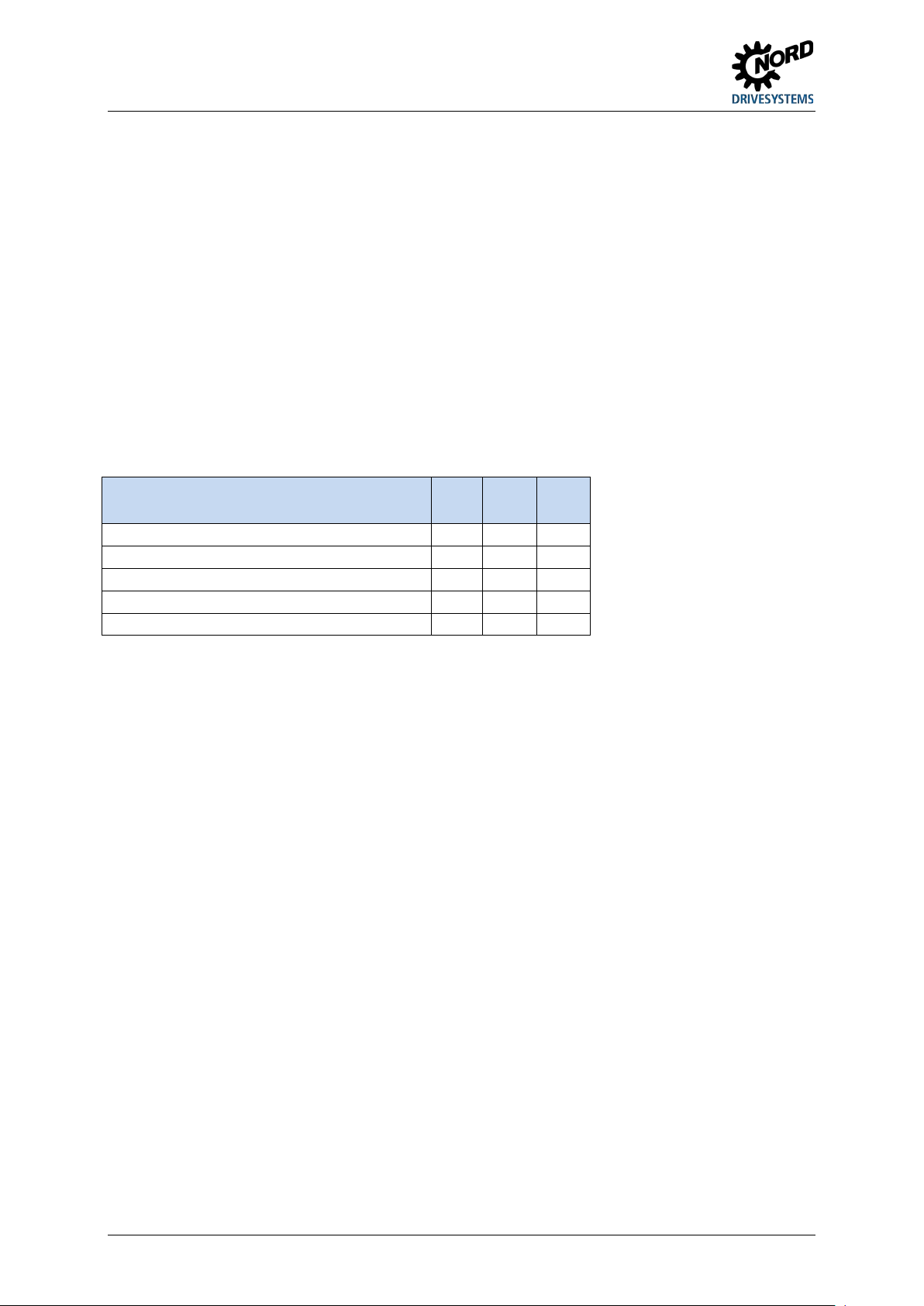
Additional features
The devices are available without an integrated field bus and alternatively in both versions (-ASI) with
integrated AS Interface and (-PBR) with integrated PROFIBUS DP.
Differences between the individual versions (SK 135E / SK 175E) are summarised in the following
table and will be described in this manual.
Feature 135E 175E-
ASI
Reversing function x x x
PROFIBUS-DP (4I / 4O) PBR
Table 2: Additional features
175E-
PBR
10 BU 0135 en-4118
Page 11
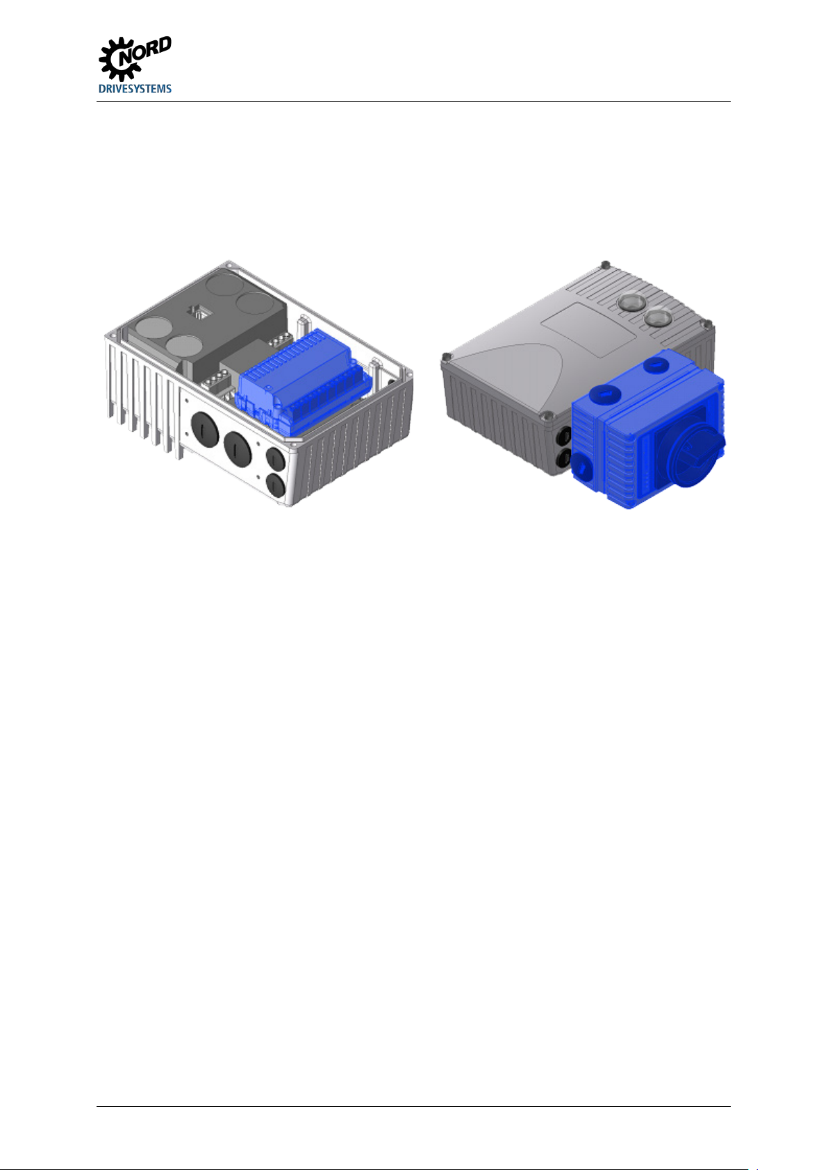
1 General
Option modules
Option modules are used to extend the functionality of the device.
These options are available as an installation variant, the so-called SK CU4-… customer unit, and also
as an attachment variant, the so-called SK TU4-… technology unit. As well as the mechanical
differences, the installation and attachment variants also have some functional differences.
Figure 1: Device with internal SK CU4-... Figure 2: Device with external SK CU4-...
Attachment variant
The external technology unit (Technology Unit SK TU4-…) is externally attached to the device and
is therefore easy to access.
A technology unit basically requires the use of a suitable SK TI4-TU-… connection unit.
The power supply and signal lines are connected using the screw clamps of the connection unit.
Depending on the version, additional connections for connectors (e.g. M12 or RJ45) may be available.
The optional wall mounting kit SK TIE4-WMK-TU also allows the technology units to be mounted away
from the starter.
Built-in variant
The internal customer unit (Customer Unit, SK CU4-...) is integrated in the device. The power
supply and signal lines are connected using screw clamps.
BU 0135 en-4118 11
Page 12
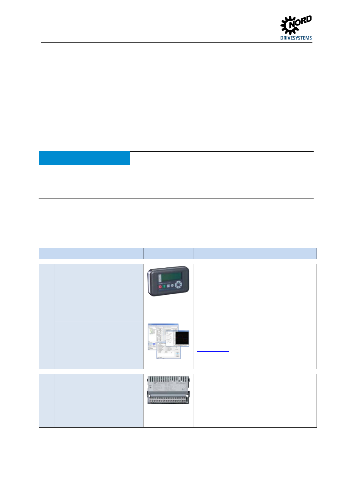
NORDAC START (SK 135E / SK 175E) – Users Manual for Motor Starters
Control and parametrisation options
For commissioning, parametrisation and control
For commissioning, parametrisation and control
IO extension
Customer unit for installation in the device for
1.2 Delivery
Check the equipment immediately after delivery / unpacking for transport damage such as
deformation or loose parts.
If there is any damage, contact the carrier immediately and carry out a thorough assessment.
Important! This also applies even if the packaging is undamaged.
1.3 Scope of delivery
NOTICE Defect in the device
Use of unapproved accessories and options (e.g. options from other device series (SK CSX-0)) may result in
defects of the interconnected components.
Only use options and accessories which are explicitly intended for use with this device and are stated accordingly
in this manual.
Standard version: • IP55 version of device (optionally IP66, IP69K)
• Operating instructions as PDF file on CD ROM including NORD CON, (PC
parametrisation software)
Available accessories:
Designation Example Description
Parametrisation units for
temporary connection to the
device, handheld
Plus connection extension
SK TIE4-RS485-RS232 (Material number
275274603)
NORD CON
MS Windows ® - based
software
Internal signal converter
of the device.
Model SK PAR-3H, SK CSX-3H
( Paragraph 3.1 "Control and parametrisation
options ")
of the device.
Refer to www.nord.com
NORD CON
(Free download)
converting bipolar analogue signals to unipolar
analogue signals, e.g. digital signals on relays
Model SK CU4-REL- …
Section 3.2.1 "Internal customer interfaces
SK CU4-… (installation of modules)"
12 BU 0135 en-4118
Page 13
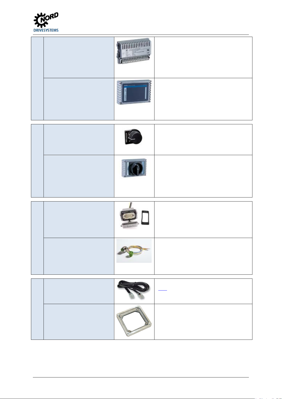
1 General
Power supply for installation in the device for
Switch for attaching to the device for ease of
Plug connector
AC Power connector for attaching to the device
Different adapter cables
Various adapter kits for attaching the device to
Internal power supplies
External power supplies
Power supply
Switch
(L – OFF – R)
Maintenance switch
Switch
(0 – I)
Power connection
(for power input, power output,
motor output)
Control line connection
Adapter cable
generating the low control voltage (24 V DC).
Model SK CU4-24V- …
Section 3.2.1 "Internal customer interfaces
SK CU4-… (installation of modules)"
Technology unit for attaching to the device or
alternatively for wall mounting (wall mounting kit
required) for generating the low control voltage
(24 V DC).
Model SK TU4-24V- …
Section 3.2.2 "External technology units
SK TU4-… (module attachment)"
controlling the device
Model SK TIE4-SWT
Section 3.1 "Control and parametrisation
options "
Technology unit for attaching to the device or
alternatively for wall mounting (wall mounting kit
required) for reliably disconnecting the device
from the power supply.
Model SK TU4-MSW- …
Section 3.2.2 "External technology units
SK TU4-… (module attachment)"
for making a detachable connection for supply
lines (e.g. mains supply line)
Model SK TIE4-…
Section 3.2.3.1 "Plug connectors for power
connections"
System connector (M12) for attaching to the
device, for making a detachable connection for
control lines
Model SK TIE4-…
Section 3.2.3.2 "Plug connectors for control
connection"
(Link)
Mounting Adapter
Adapter
BU 0135 en-4118 13
different motor sizes
Section 2.1.1.1 "Adapters for different
motors"
Page 14
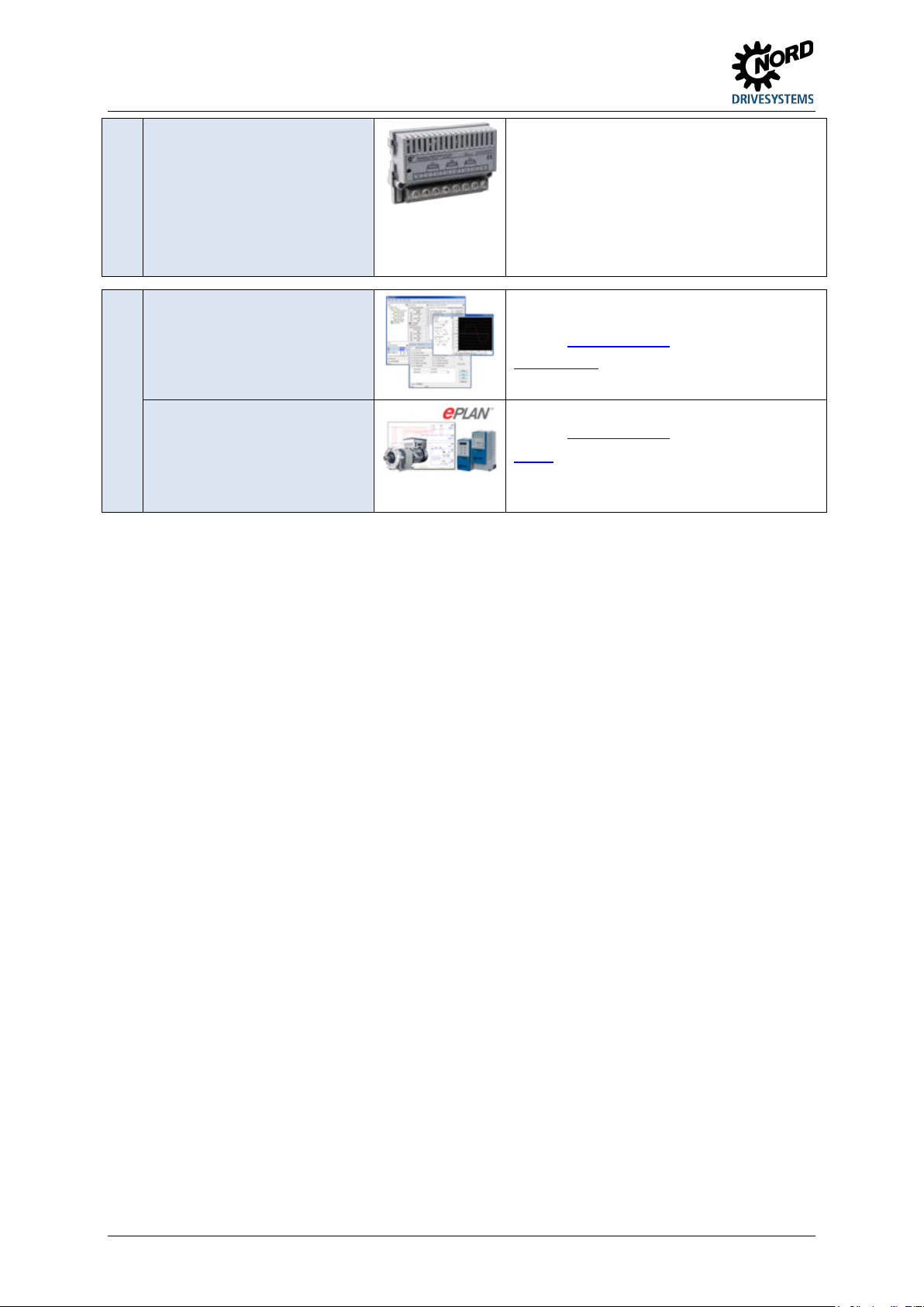
NORDAC START (SK 135E / SK 175E) – Users Manual for Motor Starters
Miscellaneous
Customer unit for installation in the device, for
Software (Free download)
Macros for producing electrical circuit diagrams
Internal fuse module
protecting the individual device in the event of
"Daisy Chain" cabling (looping through of mains
voltage from one device to the next).
Model SK CU4-FUSE- …
Section 3.2.1 "Internal customer interfaces
SK CU4-… (installation of modules)"
NORD CON
MS Windows ® - based
software
For commissioning, parametrisation and control
of the device.
Refer to
www.nord.com
NORD CON
ePlan macros
Refer to www.nord.com
ePlan
14 BU 0135 en-4118
Page 15

1 General
1.4 Safety, installation and operating instructions
Before working on or with the device, please read the following safety instructions extremely carefully.
Please pay attention to all other information from the device manual.
Non-compliance can result in serious or fatal injuries and damage to the device or its surroundings.
These safety instructions must be kept in a safe place!
1. General
Do not use defective devices or devices with defective or damaged housings or missing covers (e.g.
blind plugs for cable glands). Otherwise there is a risk of serious or fatal injuries caused by electric
shock or bursting electrical components such as powerful electrolytic capacitors.
Unauthorised removal of covers, improper use, incorrect installation or operation causes a risk of
serious personal injury or material damage.
During operation and depending on the protection class of the devices, there may be live, bare,
moving or rotating parts or hot surfaces.
The device operates with a dangerous voltage. Dangerous voltage may be present at the supply lines,
contact strips and PCBs of all connecting terminals (e.g. mains input, motor connection), even if the
device is not working or the motor is not rotating (e.g. caused by electronic disabling, jamming of the
drive or a short circuit at the output terminals).
The device is not equipped with a mains switch and is therefore always live when connected to the
power supply. Voltages may therefore be connected to a connected motor at standstill.
Even if the drive unit has been disconnected from the mains, a connected motor may rotate and
possibly generate a dangerous voltage.
If you come into contact with dangerous voltage such as this, there is a risk of an electric shock, which
can lead to serious or fatal injuries.
The device and any power plug connectors must not be disconnected while a voltage is applied to the
device. Failure to comply with this may cause arcing, which in addition to the risk of injury, also results
in a risk of damage or destruction of the device.
The fact that the status LED or other indicators are not illuminated does not indicate that the device
has been disconnected from the mains and is without voltage.
The heat sink and all other metal components can heat up to temperatures above 70 °C.
Touching these parts can result in local burns to the body parts concerned (cooling times and
clearance from neighbouring components must be complied with).
All work on the device, e.g. transportation, installation, commissioning and maintenance work must be
carried out by qualified experts (observe IEC 364 or CENELEC HD 384 or DIN VDE 0100 and
IEC 664 or DIN VDE 0110 and national accident prevention regulations). In particular, the general and
regional installation and safety regulations for work on high voltage systems (e.g. VDE) must be
complied with as must the regulations concerning correct use of tools and the use of personal
protection equipment.
During all work on the device, take care that no foreign bodies, loose parts, moisture or dust enter or
remain in the device (risk of short circuit, fire and corrosion).
Further information can be found in this documentation.
BU 0135 en-4118 15
Page 16

NORDAC START (SK 135E / SK 175E) – Users Manual for Motor Starters
2. Qualified experts
For the purposes of these basic safety instructions, qualified personnel are persons who are familiar
with the assembly, installation, commissioning and operation of this product and who have the
relevant qualifications for their work.
Furthermore, the device and the associated accessories may only be installed and started up by
qualified electricians. An electrician is a person who, because of their technical training and
experience, has sufficient knowledge with regard to
• switching on, switching off, isolating, earthing and marking power circuits and devices,
• proper maintenance and use of protective devices in accordance with defined safety standards.
3. Correct purpose of use – general
The Motor starters are devices for industrial and commercial plants for operating three-phase
asynchronous motors with squirrel-cage rotors.
The devices are components intended for installation in electrical systems or machines.
Technical data and information for connection conditions can be found on the rating plate and in the
documentation, and must be complied with.
The devices may only be used for safety functions which are described and explicitly approved.
CE-labelled devices fulfil the requirements of the Low Voltage Directive 2014/35/EU. The stated
harmonized standards for the devices are used in the declaration of conformity.
a. Supplement: Correct purpose of use within the European Union
When installed in machines, the devices must not be commissioned (i.e. commencement of
proper use) until it has been ensured that the machine fulfils the provisions of EC Directive
2006/42/EC (Machinery Directive); EN 60204-1 must also be complied with.
Commissioning (i.e. start-up of proper use) is only permitted if the EMC directive (2014/30/EU)
has been complied with.
b. Supplement: Correct purpose of use outside the European Union
The local conditions of the operator for the installation and commissioning of the device must be
complied with at the usage location (see also "a) Supplement: Correct purpose of use within the
European Union").
4. Phases of life
Transport, storage
The information in the manual regarding transport, storage and correct handling must be complied
with.
The permissible mechanical and climatic ambient conditions (see technical data in the manual for the
device) must be complied with.
If necessary, suitable, adequately dimensioned means of transport (e.g. lifting gear, rope guides) must
be used.
16 BU 0135 en-4118
Page 17

1 General
Installation and assembly
The installation and cooling of the device must be implemented according to the regulations in the
corresponding documentation. The permissible mechanical and climatic ambient conditions (see
technical data in the manual for the device) must be complied with.
The device must be protected against impermissible loads. In particular, components must not be
deformed and/or insulation distances must not be changed. Touching of electronic components and
contacts must be avoided.
The device and its optional modules contain electrostatically sensitive components, which can be
easily damaged by incorrect handling. Electrical components must not be mechanically damaged or
destroyed.
Electrical Connection
Ensure that the device and the motor are specified for the correct supply voltage.
Installation, maintenance and repair work must not be carried out unless the device has been
disconnected from the voltage and at least 5 minutes have elapsed since the mains was switched off!
(Due to charged capacitors, the equipment may continue to carry hazardous voltages for up to
5 minutes after being switched off at the mains). Before starting work it is essential to check by
measurement that all contacts of the power plug connections or the connection are voltage-free.
The electrical installation must be implemented as per the applicable regulations (e.g. cable crosssection, fuses, earth lead connections). Further instructions can be found in the documentation or
manual for the device.
Information regarding EMC-compliant installation such as shielding, earthing, location of filters and
routing of cables can be found in the documentation for the devices and in the technical information
manual TI 80-0011
. CE marked devices must also comply with these instructions. Compliance with the
limit values specified in the EMC regulations is the responsibility of the manufacturer of the system or
machine.
In case of a fault, insufficient earthing may cause an electric shock with possibly fatal consequences if
the device is touched.
The device may only be operated with effective earth connections which comply with local regulations
for large leakage currents (> 3.5 mA). Detailed information regarding connections and operating
conditions can be obtained from the technical Information manual TI 80-0019
.
The voltage supply of the device may directly or indirectly put it into operation, or touching electrically
conducting components may then cause an electric shock with possible fatal consequences.
All phases of all power connections (e.g. power supply) must always be disconnected.
Set-up, troubleshooting and commissioning
When working on live devices, the applicable national accident prevention regulations must be
complied with (e.g. BGV A3, formerly VBG 4).
The voltage supply of the device may directly or indirectly put it into operation, or touching electrically
conducting components may then cause an electric shock with possible fatal consequences.
The parametrisation and configuration of the devices must be selected so that no hazards can occur.
With certain setting conditions, the device or the motor which is connected to it may start automatically
when the mains are switched on. The machinery which it drives (press / chain hoist / roller / fan etc.)
may then make an unexpected movement. This may cause various injuries, including to third parties.
Before switching on the mains, secure the danger area by warning and removing all persons from the
danger area.
BU 0135 en-4118 17
Page 18

NORDAC START (SK 135E / SK 175E) – Users Manual for Motor Starters
Operation
Where necessary, systems in which the devices are installed must be equipped with additional
monitoring and protective equipment according to the applicable safety requirements (e.g. legislation
concerning technical equipment, accident prevention regulations, etc.).
All covers must be kept closed during operation.
With certain setting conditions, the device or the motor which is connected to it may start automatically
when the mains are switched on. The machinery which it drives (press / chain hoist / roller / fan etc.)
may then make an unexpected movement. This may cause various injuries, including to third parties.
Before switching on the mains, secure the danger area by warning and removing all persons from the
danger area.
Maintenance, repair and decommissioning
Installation, maintenance and repair work must not be carried out unless the device has been
disconnected from the voltage and at least 5 minutes have elapsed since the mains was switched off!
(Due to charged capacitors, the equipment may continue to carry hazardous voltages for up to
5 minutes after being switched off at the mains). Before starting work it is essential to check by
measurement that all contacts of the power plug connections or the connection are voltage-free.
For further information, please refer to the manual for the device.
Disposal
The product and its parts and accessories must not be disposed of as domestic waste. At the end of
its life, the product must be properly disposed of according to the local regulations for industrial waste.
In particular, this product contains integrated semiconductor circuits (PCBs and various electronic
components, including high power capacitors). In case of incorrect disposal there is a risk of formation
of toxic gases, which may cause contamination of the environment and direct or indirect injuries (e.g.
chemical burns). In the case of high power capacitors, there is also a risk of explosion, with the
associated risk of injury.
5. Potentially explosive environment (ATEX, EAC Ex)
In order to operate or carry out installation work in potentially explosive environments (ATEX,
EAC Ex), the device must be approved and the relevant requirements and notes from the manual of
the device must be complied with.
Failure to comply can result in the ignition of an explosive atmosphere and fatal injuries.
• Only persons who are qualified, i.e. trained and authorised for all assembly, service,
commissioning and operation work on association with explosion hazard environments may work
with the devices described here (including the motors, geared motors, any accessories and all
connection technology).
• Explosive concentrations of dust may cause explosions if ignited by hot or sparking objects. Such
explosions may cause serious or fatal injuries to persons or severe material damage.
18 BU 0135 en-4118
Page 19

1 General
• The drive must comply with the specifications of "Planning guideline for the operating and
installation instructions B1091" B1091-1
• Only original parts which are approved for the device and for operation in an explosion hazard area
ATEX Zone 22 3D, EAC Ex must be used.
• Repairs may only be carried out by Getriebebau NORD GmbH & Co. KG.
.
BU 0135 en-4118 19
Page 20
NORDAC START (SK 135E / SK 175E) – Users Manual for Motor Starters
Danger
Electric shock
CAUTION
Hot surfaces
NOTICE
EDS
1.5 Warning and hazard information
Under certain circumstances, hazardous situations may occur in association with the frequency
inverter. In order to give explicit warning of possibly hazardous situations, clear warning and hazard
information can be found on the device and in the relevant documentation.
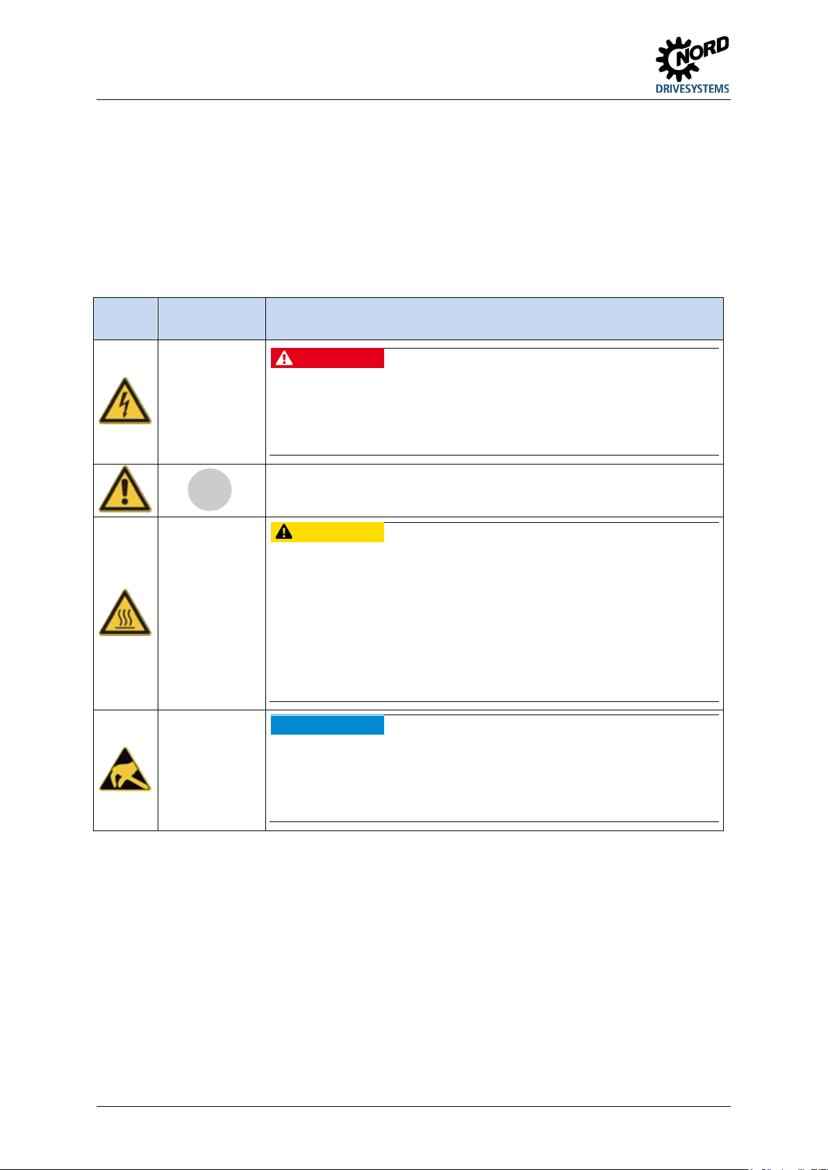
1.5.1 Warning and hazard information on the product
The following warning and hazard information is used on the product.
Symbol
Supplement to
symbol 1)
DANGER
Device is live
> 5min after
removing mains
voltage
Meaning
The device contains powerful capacitors. Because of this, there may be a
hazardous voltage for more than 5 minutes after disconnection from the mains.
Before starting work, check that the device is free of voltage at all power
contacts by means of suitable measuring equipment.
It is essential to read the manual in order to prevent hazards!
The heat sink and all other metal components as well as the surfaces of plug
connectors may heat up to temperatures in excess of 70°C.
• Danger of injury due to local burns on contact.
• Heat damage to adjacent objects
Allow sufficient cooling time before starting work on the device. Check the
surface temperatures with suitable measuring equipment. Maintain an
adequate distance to adjacent components or provide protection against
contact.
The device contains electrostatically sensitive components, which can be
easily damaged by incorrect handling.
Avoid all contact (indirect contact by tools or similar, or direct contact) with
PCBs and their components.
1) Texts are written in English.
Table 3: Warning and hazard information on the product
20 BU 0135 en-4118
Page 21
1 General
Low Voltage
UL 60947-1
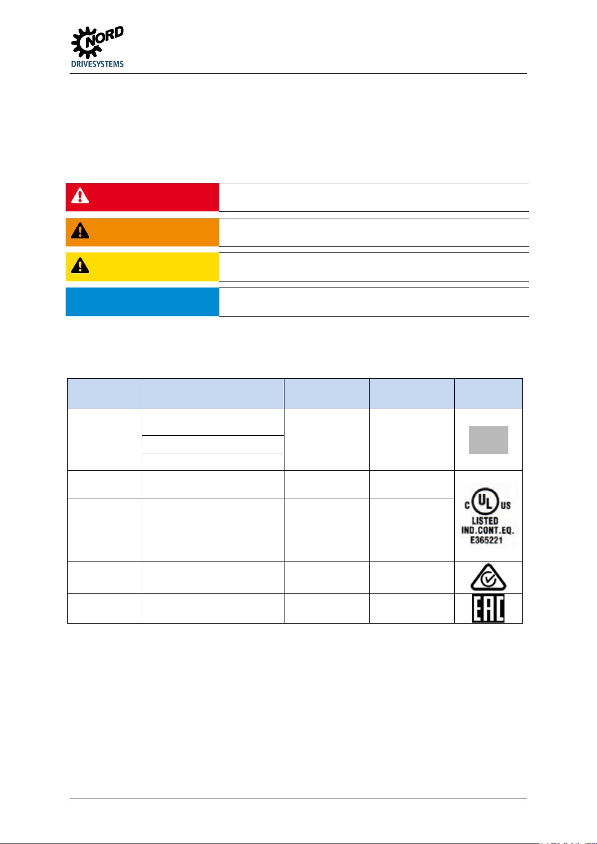
1.5.2 Warning and hazard information in the document
The warning and hazard information in this document are located at the beginning of the section which
describes the action which may result in the corresponding hazards.
The warning and hazard information is classified as follows according to the risk and the severity of
the resulting injuries.
DANGER!
WARNING
CAUTION
NOTICE
Indicates an immediate danger, which may result in death or serious injury.
Indicates a possibly dangerous situation, which may result in death or
serious injury.
Indicates a possibly dangerous situation, which may result in slight or
minor injuries.
Indicates a possibly harmful situation, which may cause damage to the
product or the environment.
1.6 Standards and approvals
All devices of the entire SK 200E series comply with the standards and directives listed below.
Approval Directive
CE
(European
Union)
Directive
EMC 2014/30/EU
RoHS 2011/65/EU
UL
(USA)
CSA
(Canada)
2014/35/EU
Applied
standards
EN 60947-1
EN 60529
EN 60947-4-2
EN 50581
UL 60947-4-2
C22.2
No.UL 60947-1-13
C22.2
No.UL 60947-4-214
Certificates Code
C310800
E365221
E365221
C-Tick
(Australia)
EAC
(Eurasia)
Table 4: Standards and approvals
N 23134
TR CU 004/2011,
TR CU 020/2011
IEC 60947-1
IEC 60947-4-2
TC RU CDE.AЛ32.B.01859
BU 0135 en-4118 21
Page 22
NORDAC START (SK 135E / SK 175E) – Users Manual for Motor Starters
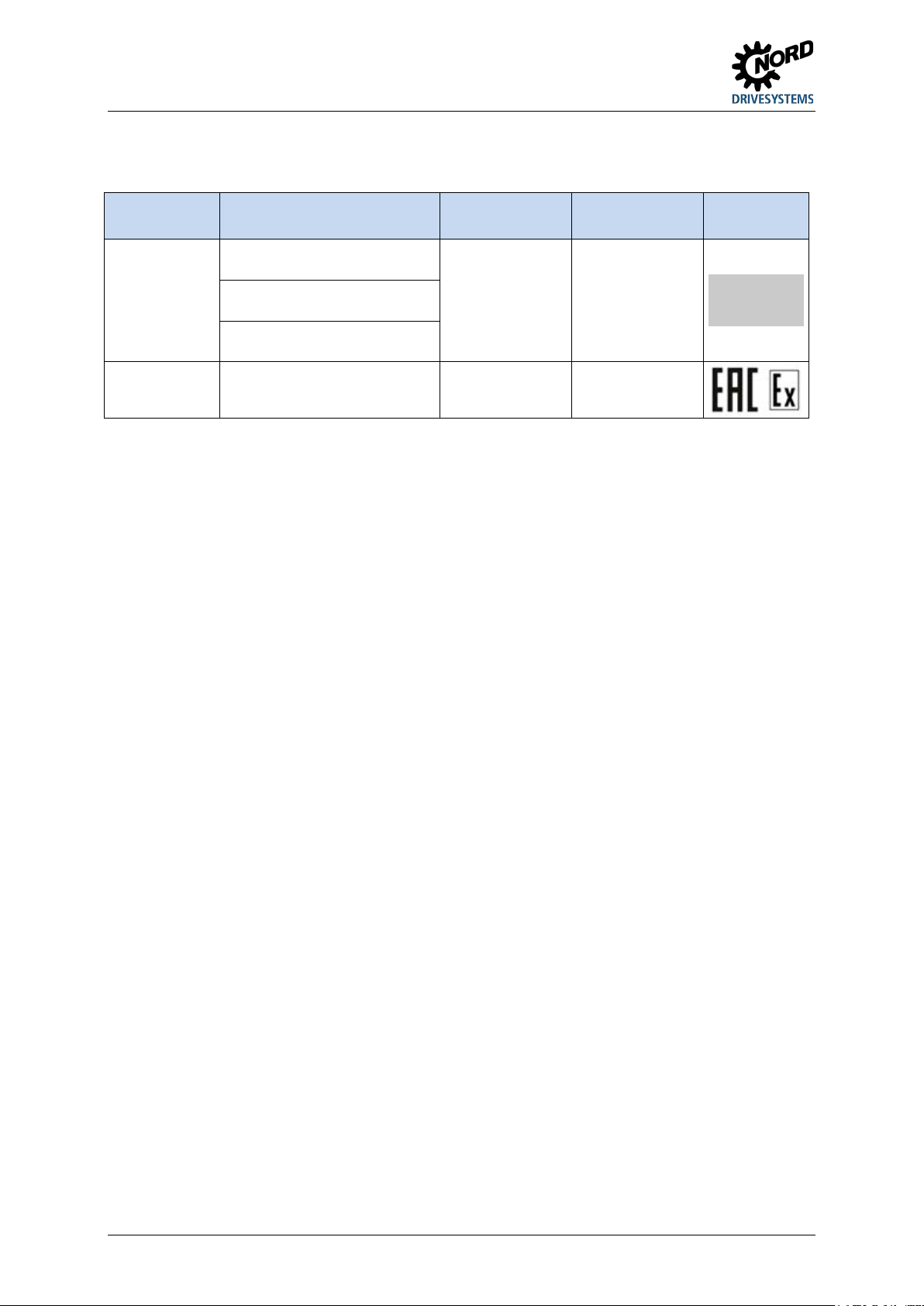
Devices which are configured and approved for use in explosion hazard environments ( Section 2.4
"Operation in potentially explosive environments ") comply with the following directives and standards.
Approval Directive
ATEX 2014/34/EU
ATEX
(European
EMC 2014/30/EU
Union)
RoHS 2011/65/EU
EAC Ex
(Eurasia)
Table 5: Standards and approvals for explosion hazard environments
TR CU 012/2011
Applied
standards
EN 60079-0
EN 60079-31
EN 61800-5-1
EN 60529
EN 61800-3
EN 50581
IEC 60079-0
IEC 60079-31
Certificates Code
C432810
TC RU CDE.AA87.B.01108
22 BU 0135 en-4118
Page 23
1 General
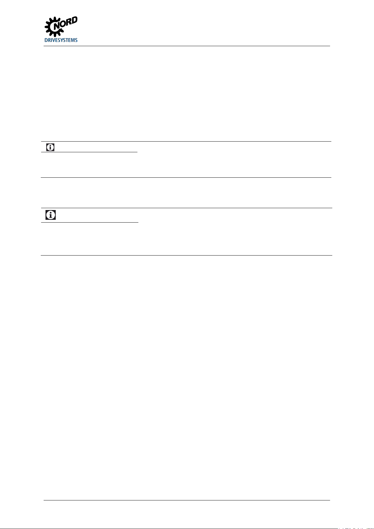
Information
Group fuse protection
1.6.1 UL and CSA approval
File No. E365221
Categorisation of protective devices approved by the UL according to United States Standards for the
inverters described in this manual is listed below with essentially the original wording. The
categorisation of individually relevant fuses or circuit breakers can be found in this manual under the
heading “Electrical Data”. All devices include motor overload protection.
( section 7.2 "Electrical data")
The devices can basically be protected as a group via a common fuse (details in the following). The adherence of
the total currents and the use of the correct cables and cable cross-sections must be taken into account when
doing this. If the device or devices is/are being installed close to the motor, this also applies to the motor cable.
UL / CSA conditions according to the report
Information
“Use 60/75°C copper field wiring conductors.”
„These products are intended for use in a pollution degree 2 environment“
“The device has to be mounted according to the manufacturer instructions.”
BU 0135 en-4118 23
Page 24
NORDAC START (SK 135E / SK 175E) – Users Manual for Motor Starters
Interrupting Capacity, Current
Motor group
Size valid description
1 - 2 generally valid “Suitable For Use On A Circuit Capable Of Delivering Not More Than 100 000 rms Symmetrical
installation
(Group fusing):
differing data
CSA:
1)
( 7.2)
Amperes, 500 Volts Maximum” “When Protected by class RK5 Fuses or faster, rated ______
Amperes, and 500 Volts”, as listed in
1)
.
“Suitable For Use On A Circuit Capable Of Delivering Not More Than 100 000 rms Symmetrical
Amperes, 500 Volts Maximum” “When Protected by HighLimiting Class CC, G, J, L, R, T, etc., as listed in 1).
“Suitable For Use On A Circuit Capable Of Delivering Not More Than 65 000 rms Symmetrical
Amperes, 480 Volt maximum”,
“When Protected by Circuit Breaker (inverse time trip type) in accordance with UL 489, rated
______ Amperes, and 480 Volts”, as listed in
1)
, Rated short circuit current min. 65 kA
"Suitable For Use On A Circuit Capable Of Delivering Not More Than 100 000 rms Symmetrical
Amperes, 500 Volts Max., When Protected by internal device SK CU4-FUSE”
“Suitable for motor group installation on a circuit capable of delivering not more than 100 000
rms symmetrical amperes, 500 V max” “When Protected by class RK5 Fuses or faster, rated
30_Amperes and 500 Volts.”
“Suitable for motor group installation on a circuit capable of delivering not more than 100 000
rms symmetrical amperes, 500 V max” “When Protected by High-Interrupting Capacity, Current
Limiting Class CC, G, J, L, R, T, etc. Fuses rated 30 Amperes”
“Suitable for motor group installation on a circuit capable of delivering not more than 65 000
rms symmetrical amperes, 480 V max” “When Protected by Circuit Breaker (inverse time trip
type) in accordance with UL 489, rated 30 Amperes and 500 Volts, 480 V min”
None differing data equal to UL
24 BU 0135 en-4118
Page 25
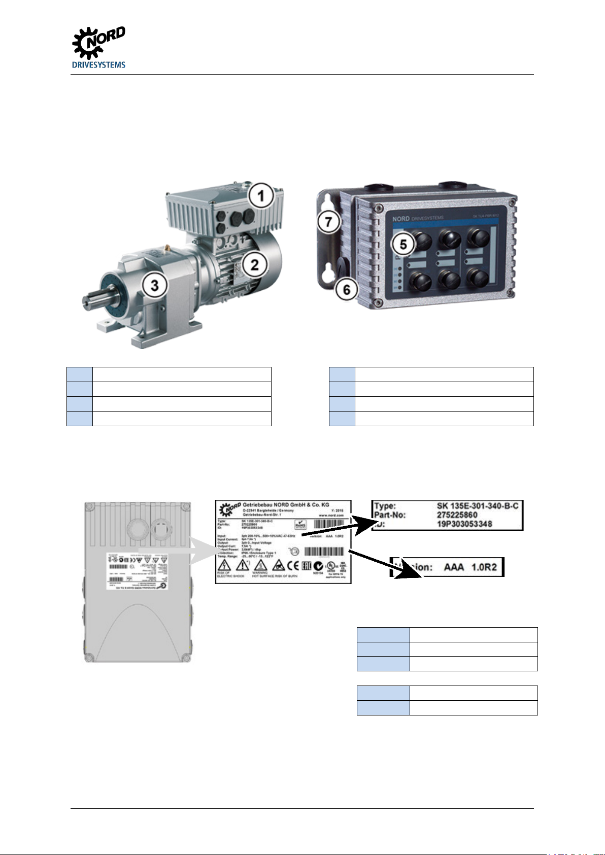
1 General
1
Motor starters
5 Optional module
2
6
3
Gear units
7 Wall-mounting kit
Legend
Type:
Type / designation
ID:
Device ident number
FW:
Firmware version (x.x Rx)
HW:
Hardware version (xxx)
1.7 Type code / nomenclature
Unique type codes have been defined for the individual modules and devices. These provide
individual details of the device type and its electrical data, protection class, fixing version and special
versions. A differentiation is made according to the following groups:
Motor
Connection unit
1.7.1 Name plate
All of the information which is relevant for the device, including information for the identification of the
device can be obtained from the type plate.
Part No.: Part Number
Figure 3: Name plate
BU 0135 en-4118 25
Page 26
NORDAC START (SK 135E / SK 175E) – Users Manual for Motor Starters
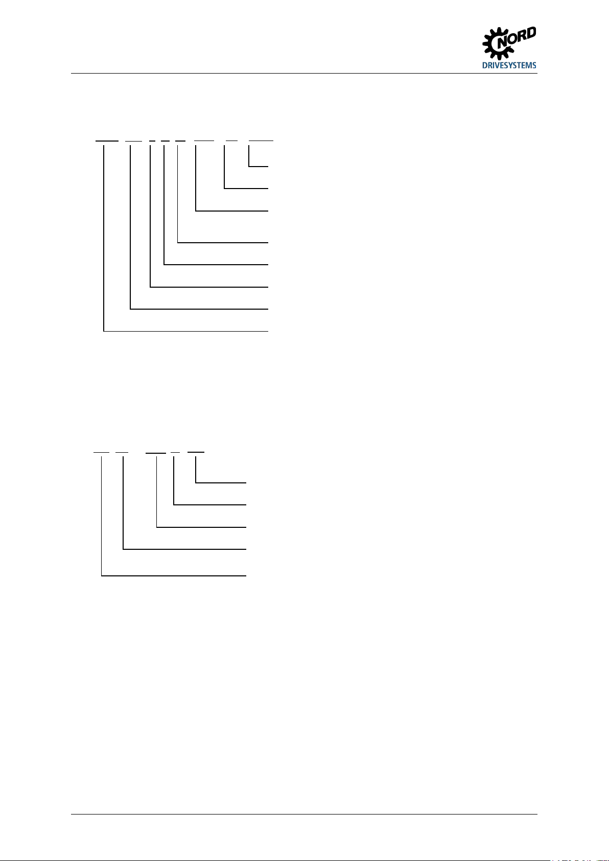
Special version
IP protection class: Standard = IP55, C = IP66, C-NSD = IP69K
Device version: ASI – integrated AS Interface, PBR –
Radio interference filter: O = none, B= Class B
Mains voltage: x40 = 200 - 500 V
Number of mains phases: 3xx = 3-phase
Device rated power: 301 = 3.0 kW, 751 = 7.5 kW
Device series:
SK 135E, SK 175E
(...) Options, only implemented if required.
Radio interference filter: B = Class B (C1)
Mains connection: 123 = 1~ 230V, 140 = 1~ 400V
Option series:
TU4 = external technology unit (attachment),
(...) Options, only implemented if required.
1.7.2 Type code Motor starter
SK 175E-751-340-B (-ASI) (-C) (-xxx)
integrated PROFIBUS DP
1.7.3 Type code for option modules
For "PotiBox" power supply or potentiometer modules
SK TU4-24V-123-B (-C)
IP protection class: Standard = IP55, C = "coated" = IP66
Option type: 24V = 24V power supply, POT = Potentiometer/switch
module
CU4 = internal customer unit (installation)
26 BU 0135 en-4118
Page 27
1 General
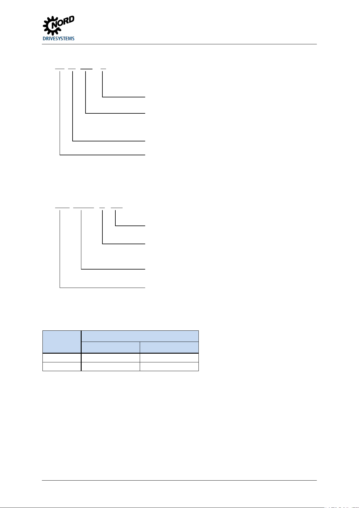
IP protection class: Standard = IP55, C = "coated" IP66
Suitable
NET = Mains option module (e.g. TU4-24V-…)
Group: TU = Technology unit
Device series: SK TI4 = Connection unit SK TI4
(...) Options, only implemented if required.
Further details (depending on type)
Details (depending
C = IP66, EX = ATEX, PBR = PROFIBUS –
Connection extension
Size 2
2.2 ... 4.0 kW
4.0 ... 7.5 kW
The sizes that have been mentioned differ from each other in terms of
1.7.4 Type code, connection unit for technology unit
SK TI4-TU-BUS (-C)
1.7.5 Adapter Unit type code
SK TIE4-WMK-1 (-C- …)
device types:
BUS = Bus option module (e.g. CANopen:
TU4-CAO
on type)
Type (selection): WMK-1 = Wall mounting kit (version 1),
M12 = M12 plug connector for connection of signal cables,
HAN = Harting – System plug connector for power connection
1.8 Power rating / Motor size
Size 1)
Size 1 0.12 ... 1.5 kW 0.25 ... 3.0 kW
1)
the envelope dimensions. The difference is restricted to the version of
the opening for fitting the terminal box to a motor.
Mains / power assignment
3~ 200 – 240 V 3~ 380 – 500 V
Signal cable, …
BU 0135 en-4118 27
Page 28
NORDAC START (SK 135E / SK 175E) – Users Manual for Motor Starters
Information
IP66 special measures
1.9 Version in protection class IP55, IP66, IP69K
The SK 1x5E is available in IP55 (standard) or IP66, IP69K (optional). The additional modules are
available in protection classes IP55 (standard) or IP66 (optional).
A protection class that differs from the standard (IP66, IP69K) must always be specified in the order
when ordering!
There are no restrictions or differences to the scope of functionality in the protection classes that have
been mentioned. The type designation is extended accordingly in order to distinguish between the
protection classes.
e.g. SK 1x5E-221-340-A-C
Information
Cable laying
For all versions, care must be taken that the cables and the cable glands at least comply with the protection class
of the device and the attachment regulations and are carefully matched. The cables must be inserted so that
water is deflected away from the device (if necessary use loops). This is essential to ensure that the required
protection class is maintained.
IP55 version:
The IP55 version is the standard version. In this version, the two installation types motor mounted
(fitted onto the motor) and close coupled (fitted to the wall bracket) are available. All adapter units,
technology units and customer units are also available for this version.
IP66 version:
The IP66 version is a modified option of the IP55 version. Both installation types (motor-integrated,
close coupled) are also available for this version. The modules available to the IP66 design (adapter
units, technology units and customer units) have the same functionalities as the corresponding IP55
design modules.
The modules for the IP66 version are identified by an additional "-C" in the type key, and are modified with the
following special measures:
• impregnated PCBs,
• Powder coating RAL 9006 (white aluminium) for housing,
• modified blank screw caps (UV-resistant),
• Low pressure test.
IP69K version:
The IP69K version is a modified option of the IP66 version. In device with protection class IP69K, the
housing is made from nsd-tupH. Both installation types (motor-integrated, close coupled) are also
available for this version.
Additional attachments (technology units etc.) to the device are not permitted.
28 BU 0135 en-4118
Page 29
2 Assembly and installation
Information
Device version IP6x
2 Assembly and installation
2.1 Installation SK 1x5E
The devices are available in various sizes depending on their output. They can be mounted on the
terminal box of a motor or in its immediate vicinity.
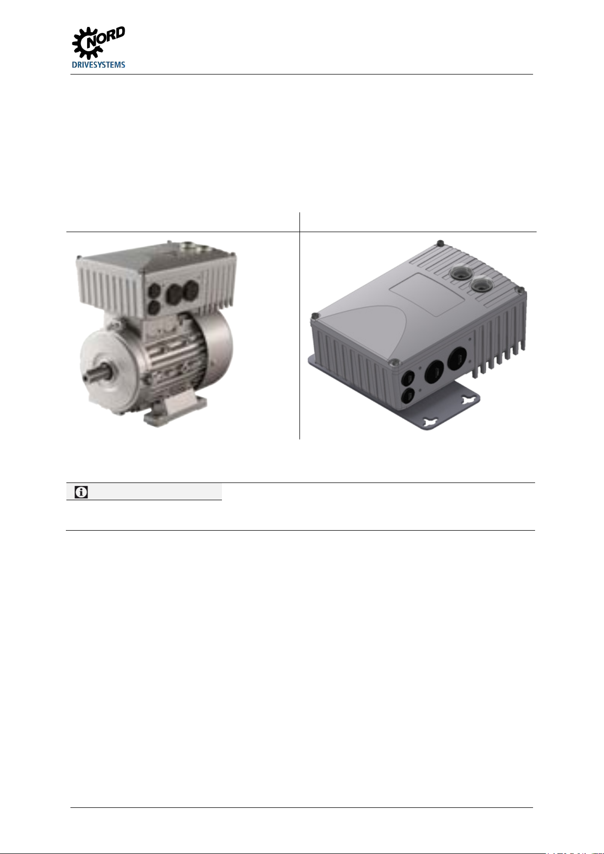
Motor-mounted version Wall-mounted version
When a complete drive unit (gear unit + motor + SK 1x5E) is delivered, the device is always fully
installed and tested.
IP6x-compliant devices must be installed by NORD, since special measures have to be implemented. IP6x
components that are retrofitted on site cannot ensure that this protection class is provided.
When delivered separately, the device includes the following components:
• SK 1x5E
• Screws and contact washers for mounting the motor terminal box
• Pre-fabricated cable for motor and PTC connections
The sizes of the device series only differ with regard to their possibilities for adapting to the matching
motors. For example, size 1 is coordinated with motor sizes 80 – 100, and size 2 is coordinated with
motor size 132. The external dimensions (envelope dimensions) of the devices are identical.
BU 0135 en-4118 29
Page 30
NORDAC START (SK 135E / SK 175E) – Users Manual for Motor Starters
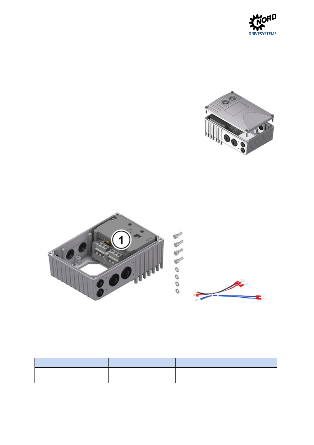
1.
If necessary, remove the original terminal box from the NORD motor, so that only the base of the terminal
. To do this, undo 4
fastening screws and then remove the casing cover vertically from
6.
Re-attach the casing cover. In order to ensure that the protection class for the device is achieved, care must
Size 1
M5 x 25
3.5 Nm ± 20 %
2.1.1 Work procedures for motor installation
box and the motor terminal strip remain.
2. Set the bridges for the correct motor circuit at the motor terminal strip, and connect the pre-fabricated
cables for motor and PTC connections to the respective connection points on the motor.
Remove the casing cover from the SK 1x5E
3.
above.
4. Fit the casing of the SK 1x5E to the terminal box base of the NORD motor using the existing screws and
seal as well as the provided toothed contact washers. When doing this, align the casing so that the rounded
side is facing the direction of the A bearing cover of the motor. Carry out mechanical adaptation using the
"Adapter kit" ( Section 2.1.1.1 "Adapters for different motors"). With motors made by other manufacturers,
it must be checked whether they can be attached.
If necessary, the plastic cover (1) for the electronics must be carefully removed in order to make the screw
fastenings to the base of the terminal box. Proceed with extreme caution when doing this to avoid damage
to the exposed PCBs.
5. Make electrical connections. For the cable gland of the connecting cable, appropriate screwed connections
for cable cross-section must be used.
be taken that all the fastening screws of the housing cover are tightened crosswise, gradually and with the
torque specified in the table below.
The cable glands that are used must at least correspond to the protection class of the device.
Size SK 1x5E Screw size Tightening torque
Size 2 M5 x 25 3.5 Nm ± 20 %
30 BU 0135 en-4118
Page 31
2 Assembly and installation
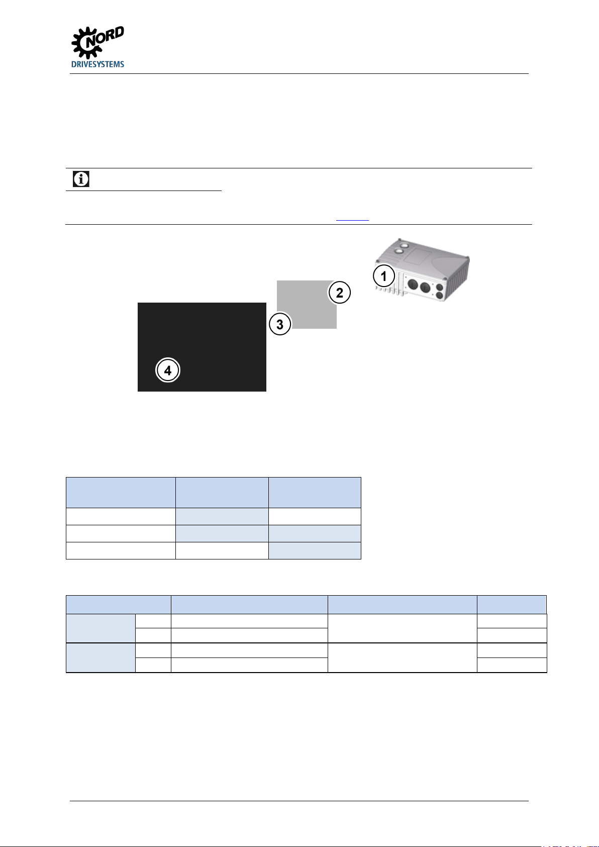
1
SK 1x5E
2
Adapter plate
3
Gasket
4 Motor, size 71
with adapter kit I
Direct mounting
with adapter kit II
Size 132
Not possible
Direct mounting
IP66
SK TI4-12-Adapter kit_63-71-C
275274324
IP55
SK TI4-3-Adapter kit_80-112
Adapter plate, terminal box frame
275274321
IP66
SK TI4-3-Adapter kit_80-112-C
275274325
2.1.1.1 Adapters for different motors
In some cases, the terminal box attachments are different for different motor sizes. Therefore, it may
be necessary to use adapters to mount the device.
In order to ensure that the maximum IPxx protection class of the device is provided for the entire unit,
all elements of the drive unit (e.g. motor) must correspond to at least the same protection class.
Information
The adaptability of motors from other manufacturers must be checked individually!
Information about converting a drive to the device can be found in BU0320
External motors
.
Figure 4: Example of motor size adaptation
NORD motor sizes Attachment
SK 1x5E size 1
Size 63 – 71
Size 80 – 112
Attachment
SK 1x5E size 2
Not possible
Overview of adapter kits
Adapter kit Name Components Part No.
Adapter kit I
Adapter kit II
BU 0135 en-4118 31
IP55 SK TI4-12-Adapter kit_63-71 Adapter plate, terminal box frame
seal and screws
seal and screws
275119050
Page 32
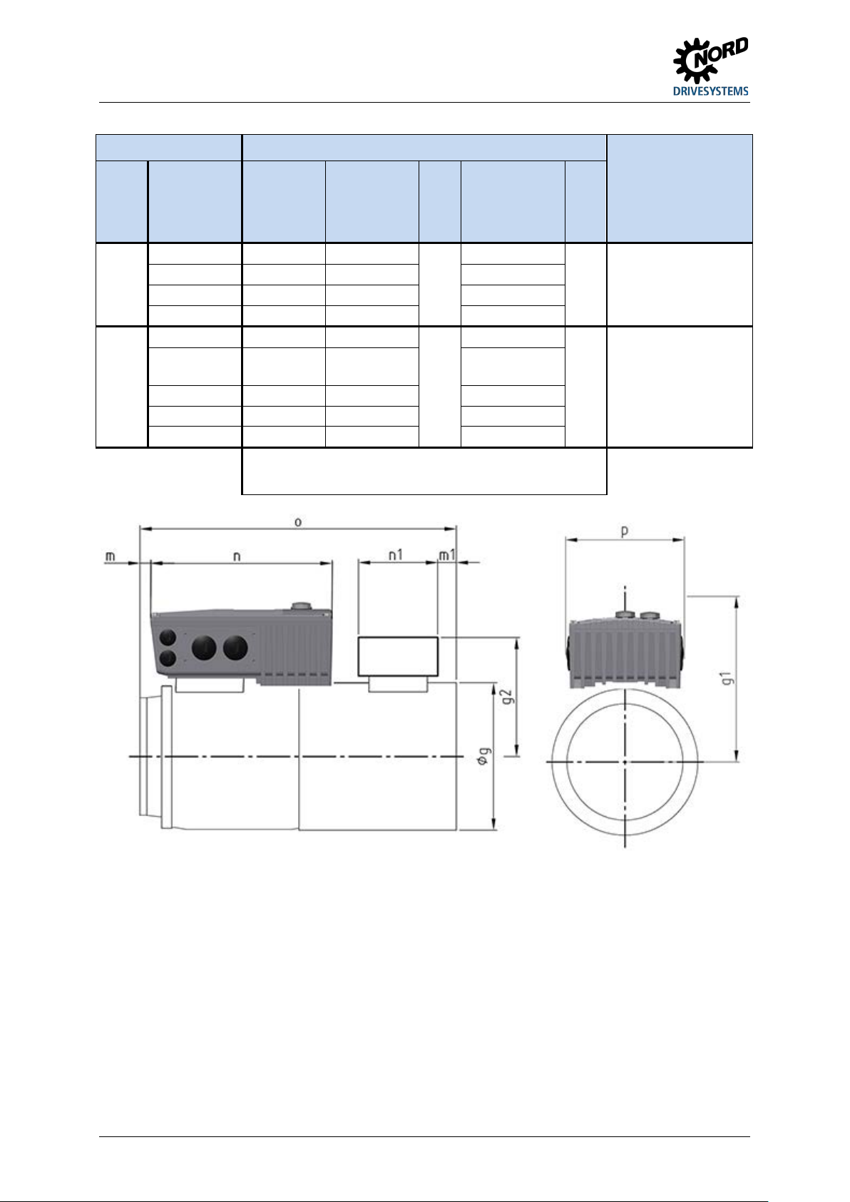
NORDAC START (SK 135E / SK 175E) – Users Manual for Motor Starters
Starter
∅
Size 71 1)
145
177.5
214
Size 90 S / L
183
176.5
251 / 276
Size 100
201
185.5
306
Size 90 S / L
Size 100 2)
201
209.5
306
Size 132 S / M
266
216.5
373 / 411
2.1.1.2 Dimensions, SK 1x5E mounted on motor
Size Housing dimensions SK 1x5E / Motor
Motor
g
g 1 n o p
Weight of SK 1x5E
without motor
Approx. [kg]
Size 1
Size 2
Size 80 165 171.5 236
2)
Size 80
2)
165 193.5
183 198.5 251 / 276
221
236
221
Size 112 2) 228 219.5 326
All dimensions in [mm]
1) incl. add. adapter and seal (18 mm) [275119050]
2) incl. add. adapter and seal (20 mm) [275274321]
154 2.1
154 2.1
32 BU 0135 en-4118
Page 33
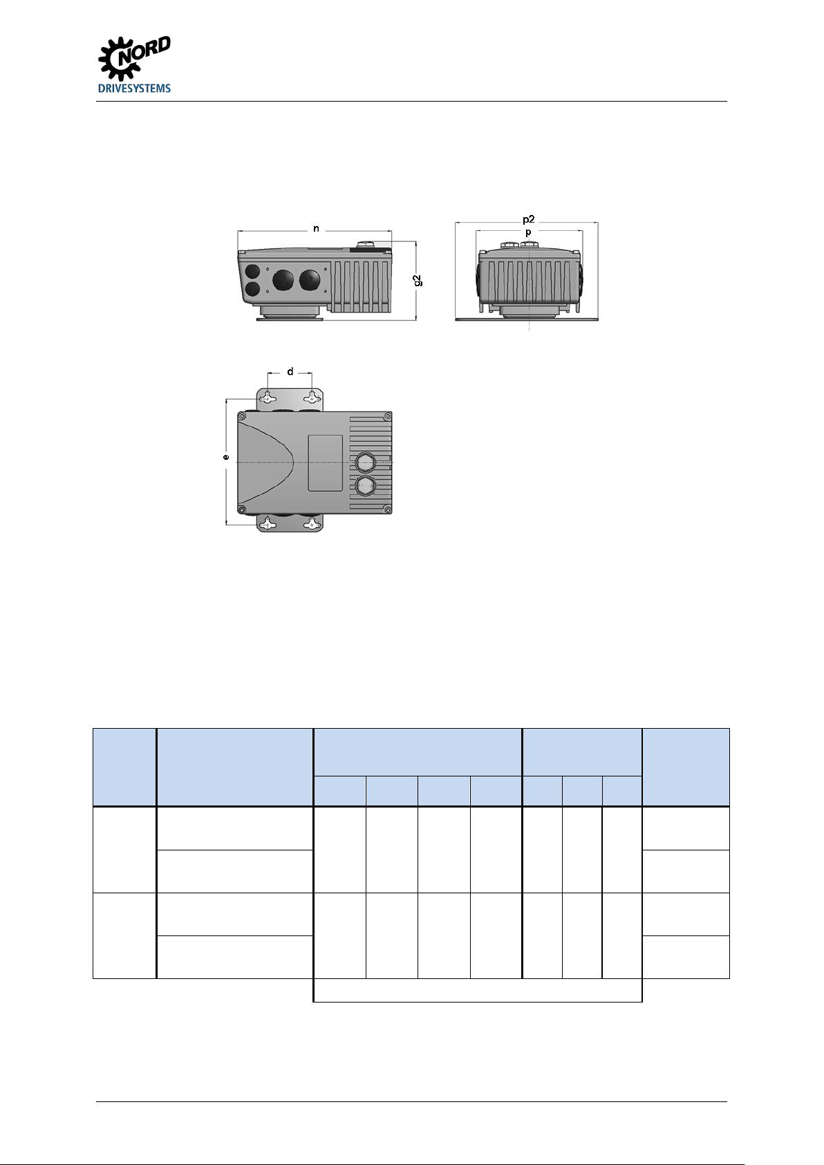
2 Assembly and installation
Size of
device
∅
All dimensions in [mm]
2.1.2 Wall mounting
As an alternative to wall mounting, the device can also be installed close to the motor using an
optional wall-mounting kit.
Wall mounting kit SK TI4-WMK-… (…1-K, …2-K, …1-NSD, 2-NSD)
This wall-mounting kit provides a simple method for installing the device close to the motor.
The SK TIE4-WMK-1-K and …2-K versions are made of plastic. They are equally suitable for IP55 and
IP66 devices.
The SK TIE4-WMK-1-NSD and ...2-NSD versions consist of stainless steel and elements which are
provided with a special NSD tupH surface treatment. These versions are intended for IP69K devices.
Any installation position is permissible with wall mounting, taking the electrical data into consideration.
Wall mounting kit Housing dimensions
Size 1 SK TIE4-WMK-1-K
Part. No. 275 274 004
SK TIE4-WMK-1-NSD
Part. No. 275 274 014
Size 2 SK TIE4-WMK-2-K
Part. No. 275 274 015
SK TIE4-WMK-2-NSD
In preparation
g2 n p p2 d e
113 221 154 205 64 180 5.5
115 221 154 235 74 210 5.5
Mounting
dimensions
Total Weight
Approx. [kg]
2.2
2.6
2.5
2.9
BU 0135 en-4118 33
Page 34
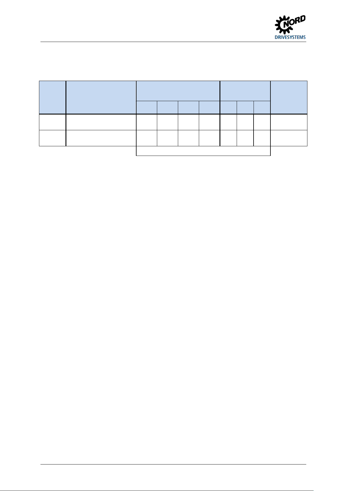
NORDAC START (SK 135E / SK 175E) – Users Manual for Motor Starters
Size of
device
∅
Part. No. 275 175 054
Wall mounting kit SK TIE4-WMK-… (…1-EX, …2-EX)
These wall mounting kits are intended for use in explosion hazard environments ( Section 2.4
"Operation in potentially explosive environments "). They are made of stainless steel and are equally
suitable for IP55 and IP66 applications.
Wall mounting kit Housing dimensions
Size 1 SK TIE4-WMK-1-EX
Part. No. 275 175 053
Size 2
SK TIE4-WMK-2-EX
Mounting
dimensions
Total Weight
Approx. [kg]
g2 n p p2 d e
113 221 154 205 64 180 5.5 2.6
115 221 154 235 74 210 5.5 2.9
All dimensions in [mm]
34 BU 0135 en-4118
Page 35
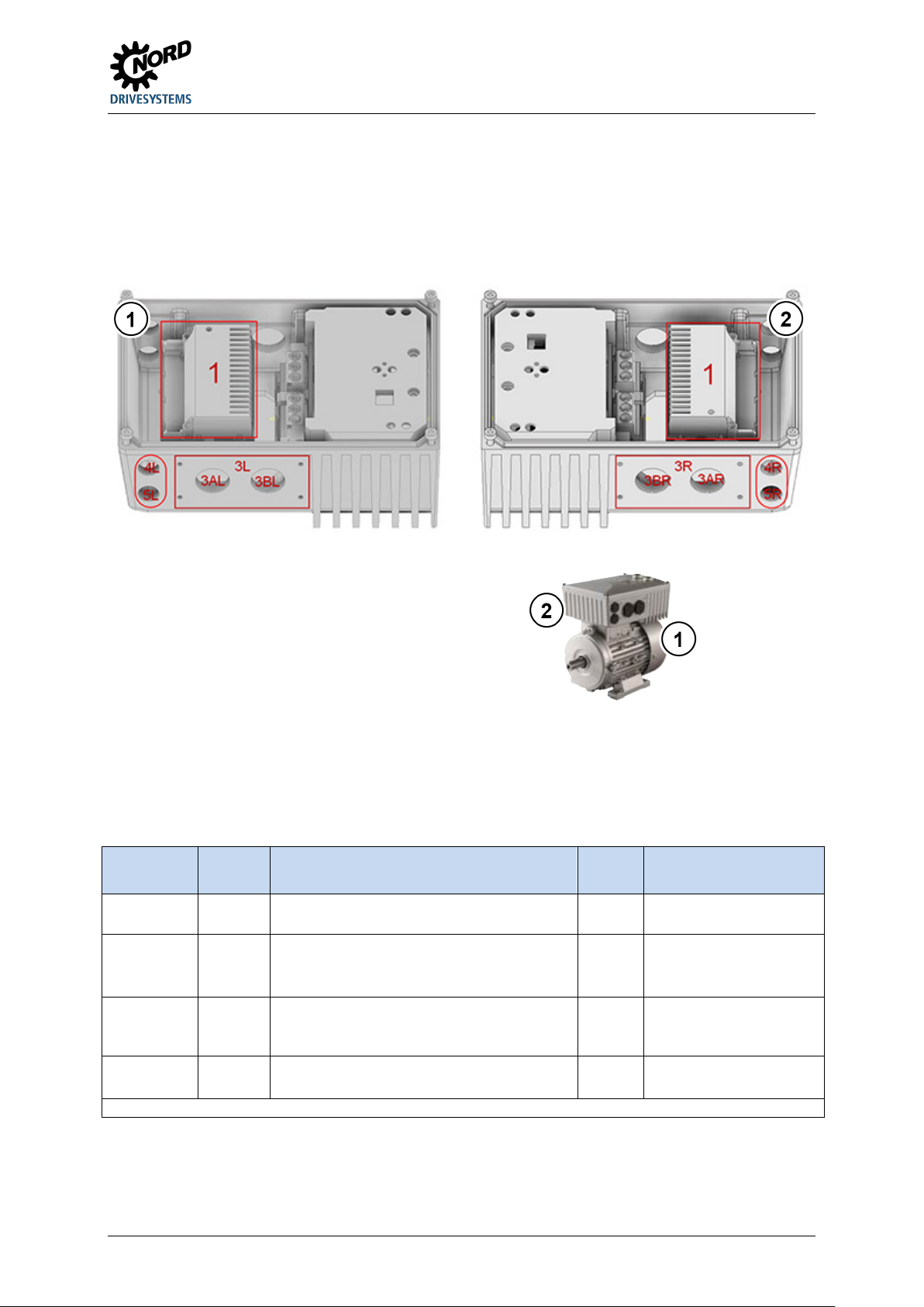
2 Assembly and installation
1
2
View from right
1
Internal
Mounting location for customer units SK CU4-
3 A/B*
on side
Cable gland
M25
Not available if location 3
4*
on side
Cable gland
M16
Not available if SK TU4-…
2.2 Installation of optional modules
Modules must not be inserted or removed unless the device is free of voltage. The slots may only be
used for the intended modules.
2.2.1 Option locations on the device
Figure 5: Option locations
View from left
The various installation locations for the optional modules are displayed in the above-mentioned
drawings. Option location 1 is used to install an internal bus module or an internal power supply.
External bus modules or 24 V DC power supplies can be implemented at option location 3L or 3R.
Option locations 4 and 5 are used to install M12 sockets or connectors or for cable glands. Only one
option can be attached in an option location, of course.
Option
location
3* on side Mounting location for
Position Meaning Size Comments
…
• external technology unit SK TU4-…
• power connector
5*
* R and L (right and left side) – with engine mounting: Viewing direction from fan impeller to motor shaft
BU 0135 en-4118 35
is occupied or SK TU4-…
is fitted.
is fitted.
Page 36
NORDAC START (SK 135E / SK 175E) – Users Manual for Motor Starters
Similar to illustration
Function
Terminal label
Cable colour
40
GND/0V
blue
L1
L2
L2
black
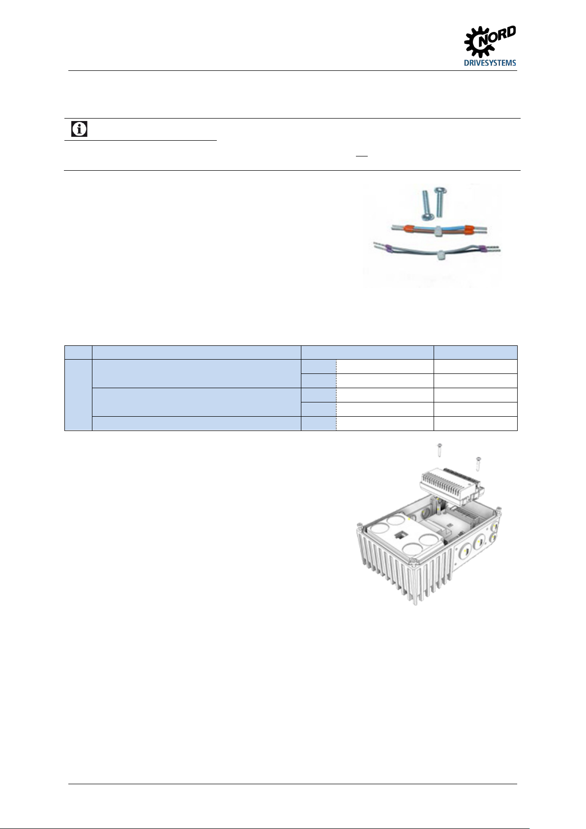
2.2.2 Installation of internal customer unit SK CU4-… (installation)
Information
Installation location of customer unit
Installation of the SK CU4-... customer unit separately from the device is not permitted. If must always be installed
inside the device in the intended position (option location 1). Only one customer unit can be installed per device!
Prefabricated cables are provided with the customer unit.
Connections are made according to the following table:
Bag enclosed with internal customer unit
Allocation of the cable sets (bag enclosed with the customer unit)
Voltage supply (24V DC)
(between device and customer unit)
Power supply (mains (AC))
(between supply network and customer unit)
44 24V brown
L1 brown
The customer units are installed inside the housing box of
the device.
The customer unit is fastened with the two screws, which are
provided.
Only one customer unit per device is possible!
36 BU 0135 en-4118
Page 37
2 Assembly and installation
Information
Detailed installation information
SK TI4-TU-NET-C
TI 275280600
SK TI4-TU-MSW-C
TI 275280700
2.2.3 Installation of external technology units SK TU4-… (attachment)
The technology units SK TU4-…(-C) require a connection unit SK TI4-TU-…(-C). This is the only way
to create a closed functional unit. This can be attached to the device or installed separately by means
of the optional SK TIE4-WMK-TU wall-mounting kit. In order to provide reliable operation, cable
lengths of more than 20 m between the technology unit and the device must be avoided.
A detailed description can be found in the documents for the connection unit concerned.
Connection unit Document
SK TI4-TU-NET TI 275280100
SK TI4-TU-MSW TI 275280200
BU 0135 en-4118 37
Page 38
NORDAC START (SK 135E / SK 175E) – Users Manual for Motor Starters
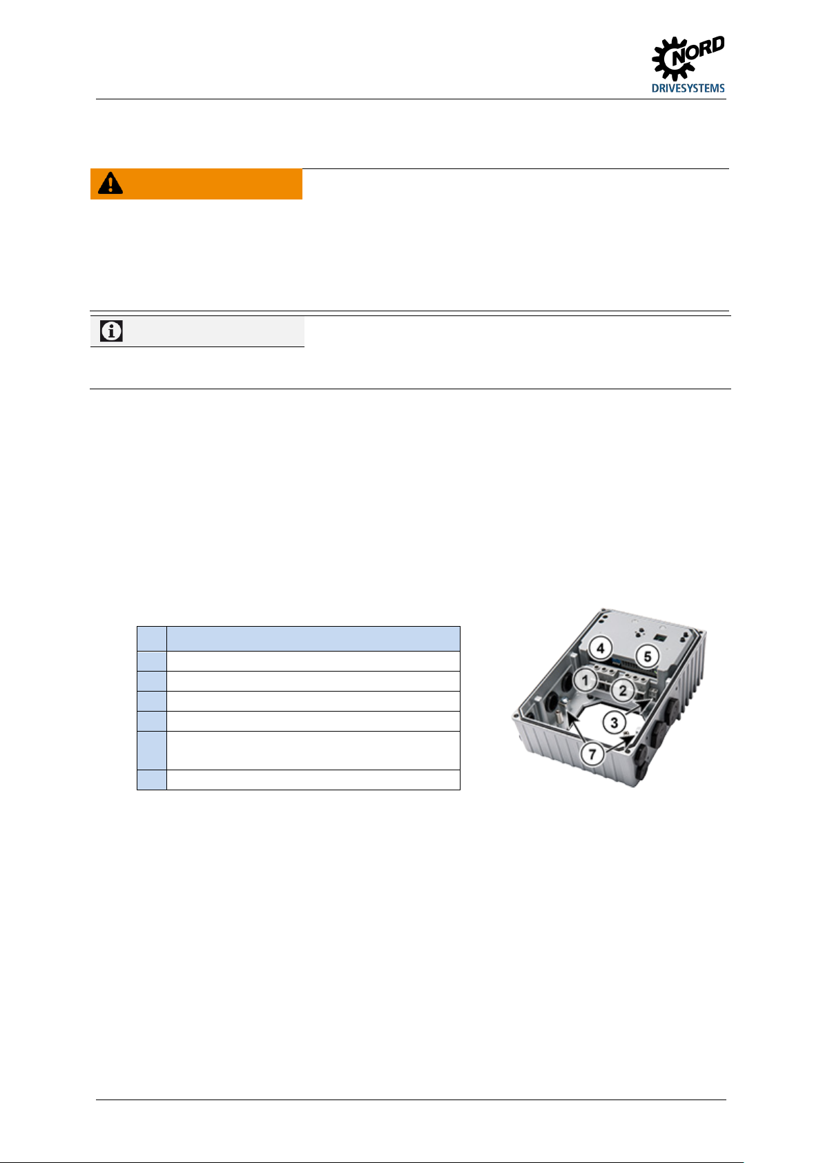
(1)
Mains cable (X1.1)
(3)
Electro-mechanical brake cables (X3)
(4)
(7)
PE (X1.2 and X2.2)
2.3 Electrical Connection
WARNING Electric shock
Dangerous voltages can be present at the mains input and the motor connection terminals even when the device
is not in operation.
• Before starting work, check that all relevant components (voltage source, connection cables, connection
terminals of the device) are free of voltage using suitable measuring equipment.
• Use insulated tools (e.g. screwdrivers).
• DEVICES MUST BE EARTHED.
Information
As with other signal cables, thermistor cables must be laid separately from the motor cables Otherwise the
interfering signals from the motor winding that are induced into the line affect the device.
Ensure that the device and the motor are specified for the correct supply voltage.
The housing cover must be removed from the device in order to make the electrical connection (
Section 2.1.1 "Work procedures for motor installation").
One terminal level is provided for the power connections and one for the control connections.
Temperature sensor and PTC (TF)
The PE connections (device earth) are located on the power connections for the motor and the mains,
as well as on the base inside the cast housing.
The terminal strip assignments differ according to the version of the device. The correct assignment
can be found on the inscription on the respective terminal or the terminal overview plan printed inside
the device.
Connecting terminals for
(2) Motor cable (X2.1)
Control lines (X4) (SK 175E only)
(5) Control lines (X5)
and motor PTC
38 BU 0135 en-4118
Page 39
2 Assembly and installation
Information
Looping of the mains voltage
2.3.1 Wiring guidelines
The soft starters have been developed for use in an industrial environment. In this environment,
electromagnetic interference can affect the device. In general, correct installation ensures safe and
problem-free operation. To meet the limiting values of the EMC directives, the following instructions
should be complied with.
1. Ensure that all devices are securely earthed to a common earthing point or earthing rail using short
earthing cables with a large cross-section. It is especially important that each control unit which is
connected to the electronic drive technology (e.g. an automatic device) has a short cable with a
large cross-section, which is connected to the same earthing point as the device itself. Flat cables
(e.g. metal stirrups) are preferable, as they have a lower impedance at high frequencies.
2. The bonding cable of the motor controlled by the soft starter should be connected directly to the
earthing terminal of the associated device. The presence of a central earthing bar in the control
cabinet and the grouping together of all bonding conductors to this bar normally ensures safe
operation.
3. Where possible, shielded cables should be used for control circuits. The shielding at the cable end
should be carefully sealed and it must be ensured that the wires are not laid over longer distances
without shielding.
The shields of analogue setpoint cables should only be earthed on one side on the device.
4. The control cables should be installed as far as possible from power cables, using separate cable
ducts, etc. Where cables cross, an angle of 90° should be ensured as far as possible.
5. Ensure that the contactors in the cabinet are interference protected, either by RC circuits in the
case of AC contactors or by free-wheeling diodes for DC contactors, for which the interference
traps must be positioned on the contactor coils. Varistors for over-voltage limitation are also
effective.
6. Shielded or armoured cables should be used for the load connections (motor cable if necessary).
The shielding or armouring must be earthed at both ends. The earthing should be provided directly
to the PE of the device if possible.
In addition, EMC-compliant wiring must be ensured.
The safety regulations must be complied with under all circumstances when installing the
devices!
NOTICE Damage due to high voltage
The device may be damaged by electrical loads which do not correspond to its specification.
• Do not perform any high voltage tests on the device itself.
• Disconnect the cable which is to be tested from the device before performing a high voltage insulation test.
The permissible current load for the connection terminals, plugs and supply cables must be observed when
looping the mains voltage. Failure to comply with this will result in thermal damage to current-carrying modules
and the immediate vicinity thereof.
If the device is installed according to the recommendations in this manual, it meets all EMC directive
requirements, as per the EMC product standard EN 60947-4-2.
BU 0135 en-4118 39
Page 40
NORDAC START (SK 135E / SK 175E) – Users Manual for Motor Starters
1 … 2
0.5 … 10
0.5 … 10
20-6
1.2 … 1.5
10.62 … 13.27
2.3.2 Electrical connection of power unit
NOTICE
This device produces high frequency interference, which may make additional suppression measures necessary
in domestic environments ( Section 8.1 "Electromagnetic compatibility (EMC)").
The use of shielded motor cables is essential in order to maintain the specified radio interference suppression
level.
When the device is being connected, please note the following:
1. Ensure that the mains supply provides the correct voltage and is suitable for the current required
( Section 7 "Technical data").
2. Ensure that suitable electrical fuses with the specified nominal current range are installed between
the voltage source and the device.
3. Mains cable connection: to terminals L1-L2/N-L3 and PE (depending on device)
4. Motor connection: to terminals U-V-W
A 4-core motor cable must be used if the device is being wall-mounted As well as U-V-W, PE must
also be connected. If present, in this case the cable shielding must be connected to a large area of
the metallic screw connector of the cable gland.
The use of wire end rings is recommended for connecting to PE.
EMC Interference to the environment
Information
Connection cables
Only use copper cables with temperature class 80°C or equivalent for connection. Higher temperature classes are
permissible.
When using wiring sleeves, the maximum connection cross-section can be reduced.
Device Cable Ø [mm²] AWG Tightening torque
Size rigid flexible [Nm] [lb-in]
Table 6: Connection data
2.3.2.1 Mains supply (L1, L2, L3, PE)
No special fuses are required at the mains input side, nor is the use of a motor protection switch
required. It is advisable to use normal mains fuses (see technical data) and a main switch.
Device data Permissible mains data
Type Voltage Power 3 ~ 230 V 3 ~ 400 V
SK…340-B 400 VAC ≥ 0.25 kW X X
Connections L1/L2/L3 L1/L2/L3
Isolation from or connection to the mains must always be carried out for all the poles and
synchronously (L1/L2/L3).
It is advisable to use a fuse module of type SK CU4-FUSE ( Section 3.2 "Optional modules").
Permissible network types
Size 1 devices can in principle be operated in TN/TT networks, as well as in IT networks. With
operation in an IT network, compliance with the EMC limit value class B cannot be ensured under the
40 BU 0135 en-4118
Page 41
2 Assembly and installation
230 V ~
105 V =
400 V ~
180 V =
500 V ~
225 V =
Information
Parameters P107 / P114
conditions stated in Section 8.1.3 "EMC of device". In this case, additional interference suppression
measures must be provided.
Size 2 devices can in principle be operated in TN/TT networks. The device must be appropriately
configured for operation in an IT network. This configuration can also be carried out at a later date;
however it can only be carried out by the manufacturer. With the operation a device which is
configured for an IT network, compliance with the EMC limit value class B cannot be ensured under
the conditions stated in Section 8.1.3 "EMC of device". In this case, additional interference
suppression measures must be provided.
Use with differing supply networks or network types
The frequency inverter may only be connect to and operated in supply networks which are explicitly
stated in this section ( Section 2.3.2.1 "Mains supply (L1, L2, L3, PE)")). Operation in deviating
network types may be possible, but must be explicitly checked and approved by the
manufacturer in advance.
2.3.2.2 Motor cable (U, V, W, PE)
The motor cable must be connected properly.
2.3.2.3 Electromechanical brake
The device generates an output voltage at terminals 79 / 80 (MB+ / MB-) for actuating an
electromagnetic brake. This is dependent on the supply voltage that is present in the device. The
allocation is as follows:
Mains voltage / AC voltage Brake coil voltage (DC)
460 V ~ / 480 V ~ 205 V =
The assignment of the correct brake and brake coil voltage must be taken into consideration in the
design with regard to the mains voltage of the device.
For the connection of an electro-mechanical brake to the terminals of the device, parameters P107 / P114 (brake
application time / release time ) must be adjusted. In order to prevent damage to the brake control, parameter
(P107) must contain a non-zero value.
BU 0135 en-4118 41
Page 42
NORDAC START (SK 135E / SK 175E) – Users Manual for Motor Starters
Cable Ø *
[mm²]
0.2 … 1.5
0.2 … 1.5
Ø cable *
[mm²]
0.2 … 0.75
0.2 … 0.75
Tightening torque
[Nm]
0.5 … 0.6
Clamping
Slotted screwdriver
[mm]
2.0
2.0
**
Flexible cable with wire-end ferrules with plastic collar (for cable cross-section 0.75 mm², a wire-end
Information
Control voltage overload
Information
Total currents
Information
Reaction time of digital inputs
Scan time
1 ms
Signal stability check
3 ms
Information
Cable laying
2.3.3 Electrical connection of the control unit
Connection data:
Terminal bar X3 X4, X5
AWG standard 24-16 24-16
[lb-in] 4.42 … 5.31
* Flexible cable with wire-end ferrules, without plastic collar or rigid cable
ferrule with a length of 10 mm must be used)
The device must be provided with an external 24 V control voltage supply. Alternatively, an optionally
available 24 V power of type SK CU4-… or SK TU4-… can be used.
The provisions in chapter 4.3 "AS Interface (AS-i)" apply to devices in which the AS interface is used.
A control unit overload caused by impermissibly high currents may destroy the unit. Impermissibly high currents
occur if the actual total current that is drawn exceeds the permissible total current or if the 24 V control voltage for
other devices is routed through the device. To avoid conduction through the frequency inverter, e.g. double wire
end ferrules must be used.
If necessary, 24 V can be drawn from several terminals. This also includes e.g. digital outputs or a operating
module connected via RJ45
The total currents which are drawn off must not exceed 200 mA (SK 175E-…-ASI: 165 mA).
The reaction time of a digital signal is approx. 4-5 ms and consists of the following:
Internal processing < 1 ms
All control cables (including thermistors) must be routed separately from the mains and the motor cables to
prevent interference in the device.
If the cables are routed in parallel, a minimum distance of 20 cm must be maintained from cables which carry a
voltage of > 60 V. The minimum distance may be reduced by screening the cables which carry a voltage, or by
the use of earthed metal partitions within the cable conduits.
Alternative: Using a hybrid cable with shielding of the control lines.
42 BU 0135 en-4118
Page 43
2 Assembly and installation
GND:
Reference potential for digital signals
DIN:
Digital input
MB+/-:
Control of electro-mechanical brake
TF+/-:
Motor thermistor (PTC) connection
SK 135E
Device type
SK 175E
ASI
PBR
GND
40 1 40
GND
DIN4 (BUS-DIN2)
C2 2 C2
DIN4 (BUS-DIN2)
DIN3 (BUS-DIN1)
C1 3 C1
DIN3 (BUS-DIN1)
(output)
(output)
ASI+
84 6 82
PBR-B
SK 135E
Device type
SK 175E
ASI / PBR
(input)
(input)
GND
40 3 40
GND
GND
40 4 40
GND
(input)
(input)
DO1
1 9 1
DO1
DO2
3
10
3
DO2
GND
40
11
40
GND
12
TF-
39
13
39
TF-
TF+
38
14
38
TF+
2.3.3.1 Control terminal details
Labelling, function
ASI+/-: Integrated AS interface PBR-A/B: Integrated PROFIBUS DP
24 V: 24 V DC control voltage DO: Digital output
Connection depending on the configuration
Terminal X3
MB+ 79 1 79 MB+
MB- 80 2 80 MB-
Terminal X4 (SK 175E only)
SK 175E Device type SK 175E
24V
ASI- 85 5 81 PBR-A
Terminal X5
Labelling
Pin
Labelling
Pin
43 4 43
Labelling
Pin
ASI / PBR
24V
24V
24V (input)
24V
BU 0135 en-4118 43
44 1 44
44 2 44
44 5 44
24V
24V (input)
24V
DIN1 21 6 21 DIN1
DIN2 22 7 22 DIN2
GND 40 8 40 GND
Page 44
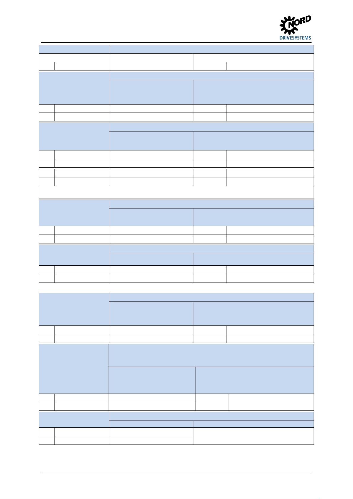
NORDAC START (SK 135E / SK 175E) – Users Manual for Motor Starters
Meaning, Functions
Description / Technical data
Digital outputs
Signalling of the operating statuses of the device
1
DO1
Digital output 1
P434 [-01]
Fault / Warning
Digital inputs
Actuation of device using an external controller, switch or the like.
21
DIN1
Digital input 1
P420 [-01]
ON right
22
C1
DIN3
Digital input 3
P420 [-04]
ON right via bus
Note: Inputs DIN3 and DIN4 are only available with the SK 175E. The signals are passed to the controller via the AS Interface or PROFIBUS DP
PTC resistor input
Monitoring of motor temperature using PTC
38
TF+
PTC resistor input
- - 39
TF-
PTC resistor input
-
-
Control voltage source
Control voltage of device, e.g. for supplying accessories.
40
GND / 0V
Reference potential GND
-
-
Control voltage
Supply voltage for the device
44
24V
Voltage input
- - 40
GND / 0V
Reference potential GND
-
-
Brake actuation
Connection and actuation of an electromechanical brake. The device generates an
80
MB-
Brake control
PROFIBUS DP
Control of device via PROFIBUS DP
81
PBR-A
PBR A
82
Terminal Parameter
No. Designation Meaning No. Function of factory setting
18 – 30 V DC, voltage level depending on
the input voltage level
3 DO2 Digital output 2 P434 [-02] Engine running
as per EN 61131-2 Type 1
Low: 0-5 V (~ 9.5 kΩ)
High: 15-30 V (~ 2.5 - 3.5 kΩ)
DIN2 Digital input 2 P420 [-02] ON left
Maximum load 200 mA, SK 175E…-ASI: 165 mA when using
the yellow cable
With inductive loads: Provide protection via free-wheeling
diode!
Scan time: 1 ms
Reaction time: ≥ 4 ms
Input capacitance: 10 nF
C2 DIN4 Digital input 4 P420 [-05] ON left via bus
and not evaluated by the device itself.
If the device is installed near the motor, a
shielded cable must be used.
The input is always active. In order to make the device
operational, a temperature sensor must be connected or both
contacts must be jumpered.
24 V DC ± 25 %, short circuit-proof
Maximum load 165 mA (SK 175E-...-ASI) / 200 mA (SK 175E...-PBR) 1)
43 VO / 24V Voltage output - -
1)
See "Total currents" information ( Section 2.3.3 "Electrical connection of the control unit")
connection
24 V DC ± 25 %
The input is not short-circuit
protected!
50 mA … 400 mA, depending on the load of inputs and
outputs and the use of options
Daisy chaining for further devices up to max. 6 A is
permissible.
output voltage for this. This depends on the mains voltage. The assignment of the
correct brake coil voltage must be taken into account in the selection.
Connected loads:
Section 2.3.2.3 "Electromechanical
brake"
Current: ≤ 500 mA
Permissible switching cycle time:
to 150 Nm ≤ 1/s
to 250 Nm ≤ 0.5/s
79 MB+ Brake control P107/114 0 / 0
PBR-B PBR-B
44 BU 0135 en-4118
Page 45
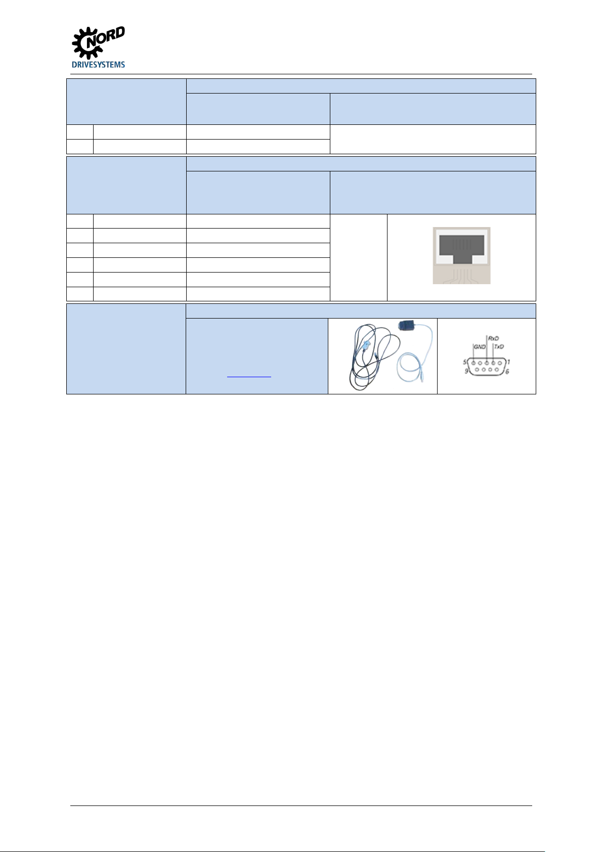
2 Assembly and installation
AS Interface
Control of device via simple field bus level: Actuator/sensor interface
85
ASI-
ASI-
Communication
Connection of device to various communication tools
2 - 3
4
RS232 TXD
Data cable RS232
5 RS232 RXD
Data cable RS232
Connection cables
Length: approx. 3.0 m + approx. 0.5 m
26.5 – 31.6 V
≤ 240 mA
Use of yellow AS interface cable
optional: Feed via black cable by means of jumper
configuration
84 ASI+ ASI+
interface
24 VDC ± 20 %
RS 232 (for connecting a PC (NORD CON))
38400 Baud
USS protocol
Address 0
1 -
GND Bus signal reference potential
6 +24 V Voltage output 1 - 2 - 3 - 4 - 5 - 6
Connection of the device to an MS-Windows® PC with NORDCON software
(accessories / optional)
Part number: 275274604
Suitable for connection to a USB port in a
PC or alternativel y to a SUB-D9
connection.
Details: TI 275274604
BU 0135 en-4118 45
Page 46
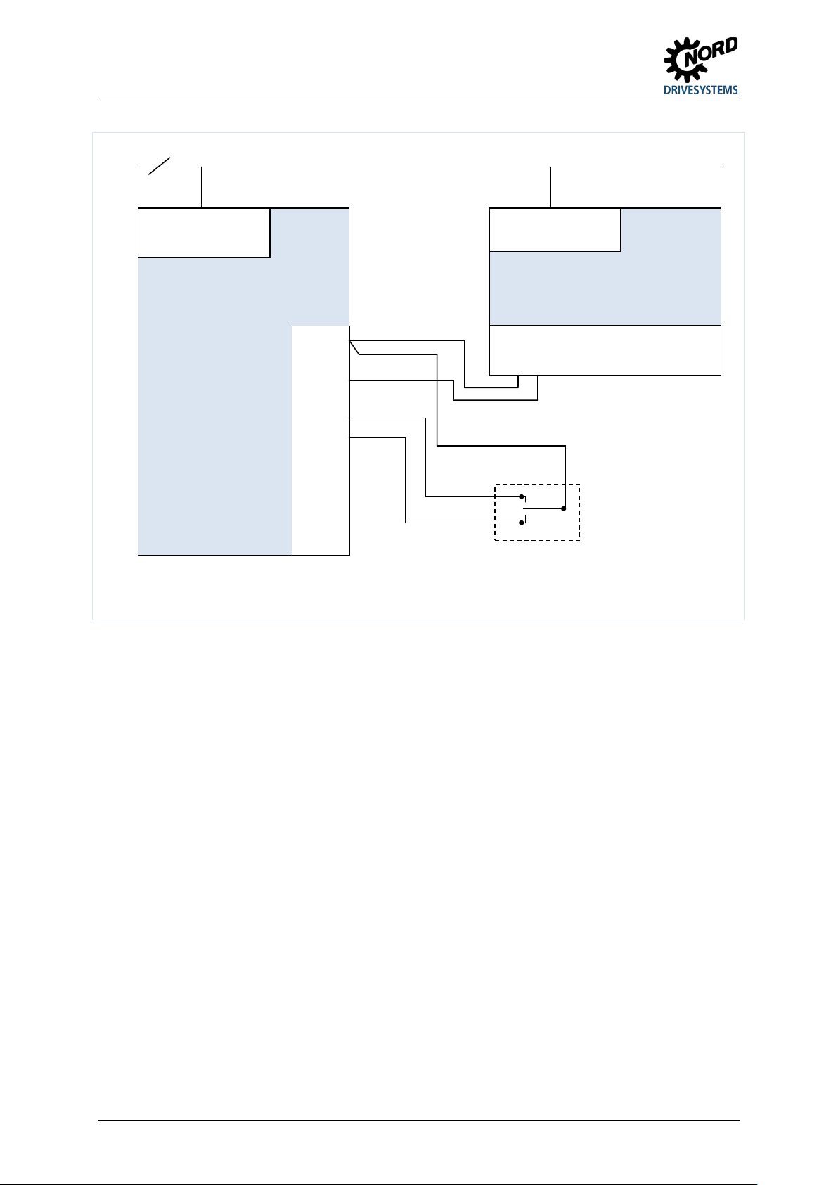
NORDAC START (SK 135E / SK 175E) – Users Manual for Motor Starters
Device
SK 1x5E-...
Control terminal bar
44
.
40
.
21
22
.
.
.
.
.
L1 - L2/N - L3
230/400V
24V power supply
SK TU4-24V-...
(+ SK TI4-TU-NET)*
and
SK CU4-24V-...
L1 - L2/N
230/400V
24V=
GND
R
L
3~ 230/400V + PE
Control terminal bar
44* 40 44* ... 11 14 12 B1
Switch
* for SK TU4-24V-… : Terminal designation 43 instead of 44
2.3.3.2 Power supply SK xU4-24V-… - Connection example
Figure 6: Connection example, power supply SK xU4-24V-…
46 BU 0135 en-4118
Page 47
2 Assembly and installation
2.4 Operation in potentially explosive environments
WARNING
Electric sparks may ignite an explosive atmosphere.
• Do not open the device in an explosive atmosphere and do not remove any covers (e.g.
diagnostic openings).
• All work on the device must only be carried out with the power to the system switched
off.
• Wait for the required time (≥ 30 min) after switching off.
• Before starting work, check that all relevant components (voltage source, connection
cables, connection terminals of the device) are free of voltage using suitable measuring
WARNING
equipment.
High temperatures may cause the ignition of an explosive atmosphere.
Temperatures may occur within the device and the motor, which are higher than the maximum
permissible surface temperature of the housing. Dust deposits may restrict the cooling of the
device.
• Clean the device at regular intervals to prevent the accumulation of impermissible dust
deposits.
• Do not open or remove the device from the motor in an explosive atmosphere.
With appropriate modification, the device can be used in certain potentially explosive areas.
Danger of explosion due to electricity
Explosion hazard due to high temperatures
If the device is connected to a motor and a gear unit, the EX labelling of the motor and the gear unit
must also be observed. Otherwise the drive must not be operated.
BU 0135 en-4118 47
Page 48
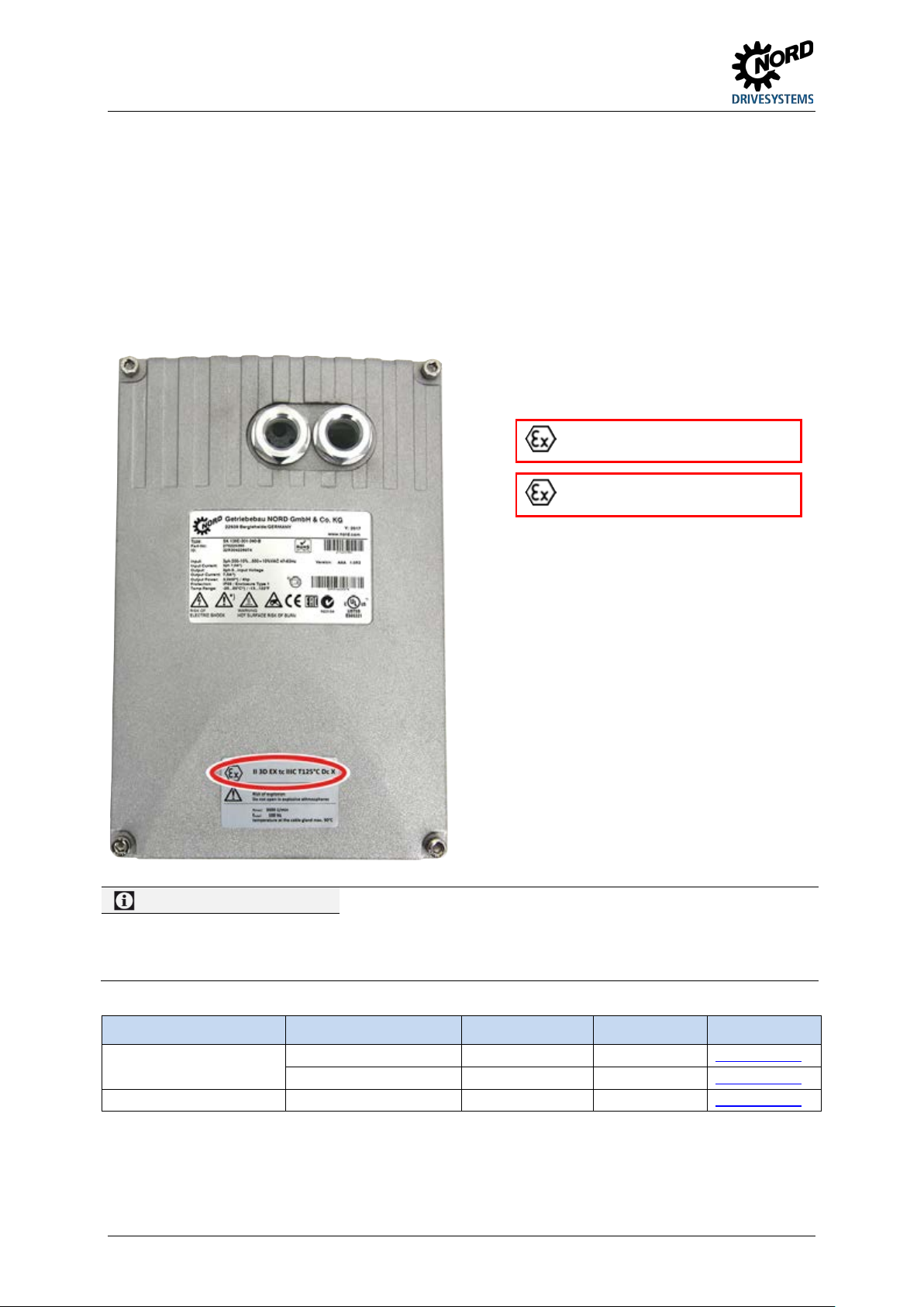
NORDAC START (SK 135E / SK 175E) – Users Manual for Motor Starters
Information
Potential damage
SK 1x5E-…
(IP55)
SK 1xxE-ATEX-IP55
275274207
1 piece
TI 275274207
SK 1x5E-…-C
(IP66)
SK 1xxE-ATEX-IP66
275274208
2 pieces
TI 275274208
2.4.1 Operation in potentially explosive environments - ATEX zone 22 3D
All of the conditions which must be observed for operation of the frequency inverter in an explosion
hazard environment (ATEX) are listed below.
2.4.1.1 Modification of the device for compliance with Category 3D
Only a specially modified device is permissible for operation in ATEX zone 22. This adaptation is only
made at the NORD factory. In order to use the device in ATEX Zone 22, the diagnostic caps are
replaced with aluminium / glass versions, among other things.
( 1 ) Year of manufacture
( 2 ) Marking of the device (ATEX)
IP55:
IP66:
II 3D Ex tc IIIB T125 °C Dc X
II 3D Ex tc IIIC T125 °C Dc X
Categorisation:
• Protection with "housing"
• Procedure "A" Zone "22" Category 3D
• Protection class IP55 / IP66 (according to the
device)
IP66 is required for conductive dust
• Maximum surface temperature 125°C
• Ambient temperature -20°C to +40°C
Devices in series SK 1x5E and the permitted options are only designed for a degree of mechanical stress that
corresponds to a low impact energy of 7J.
Higher loads will lead to damage to or in the device.
The necessary components for making adaptations are contained in the ATEX kits.
Device Kit designation Part Number Quantity Document
SK 1xxE-ATEX-IP66 275274208 1 piece TI 275274208
2.4.1.2 Options for ATEX Zone 22, category 3D
In order to ensure that the device is ATEX-compliant, its optional modules must also be approved for
potentially explosive areas. Option modules that are not in the following list may not be used in an
48 BU 0135 en-4118
Page 49
2 Assembly and installation
Power supply
SK CU4-24V-140-B(-C)
275271109 / (275271609)
Yes
Fuses
Wall mounting kits
SK TIE4-WMK-2-EX
275175054
Yes
Adapter kits
SK TI4-3-Adapter kit_80-112-EX
275175039
Yes
ATEX zone 22 3D. This also includes connectors and switches that may also not be used in such an
environment.
Control and parametrisation units are basically not approved for operation in ATEX zone 22 3D.
They may therefore only be used for commissioning or maintenance purposes and if it has been
ensured that no explosive dust atmosphere exists.
Designation Part Number Use permissible
SK CU4-24V-123-B(-C) 275271108 / (275271608) Yes
SK CU4-FUSE(-C) 275271122 / (275271622) Yes
SK TIE4-WMK-1-EX 275175053 Yes
SK TI4-12-Adapter kit_63-71-EX 275175038 Yes
2.4.1.3 Commissioning information
For Zone 22 the cable glands must at least comply with protection class IP55. Unused openings must
be closed with blank screw caps that are suitable for ATEX Zone 22 3D (generally IP 55).
The motors are protected from overheating by the device. This takes place by means of evaluation of
the motor PTC (TF) at the device side. In order to ensure this function, the PTC must be connected to
the intended input (Terminal 38/39).
It must also be ensured that the nominal current of the motor has been set.
Overview of required parameter settings:
Parameter Setting value Factory setting Description
P203
Rated motor current
Data according to
rating plate
[xxx]
Setting takes place at the factory side or must
be carried out as per the motor type plate.
The I²t- monitoring of the motor must be
P535
I²t motor
According to motor
and ventilation
[0]
switched on. The set values depend on the
type of ventilation and the motor used. See
B1091-1
BU 0135 en-4118 49
Page 50
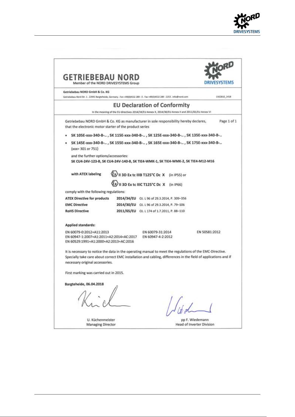
NORDAC START (SK 135E / SK 175E) – Users Manual for Motor Starters
2.4.1.4 EU conformity declaration - ATEX
50 BU 0135 en-4118
Page 51
2 Assembly and installation
Protection class IP55 / IP66 (depending on
Information
Code "U"
Information
Code "X"
2.4.2 Operation in potentially explosive environments - EAC Ex
All of the conditions which must be observed for operation of the frequency inverter in an explosion
hazard environment according to EAC Ex are listed below. All of the conditions according to
Section 2.4.1 "Operation in potentially explosive environments - ATEX zone 22 3D "apply .
ng to EAC EX are described below and must be Deviations which are relevant for approval accordi
complied with.
2.4.2.1 Modification of the device
Section 2.4.1.1 "Modification of the device for compliance with Category 3D"applies.
The labelling of the device according to EAC Ex differs as follows.
Labelling of the device:
The following applies for wall mounted devices;
IP55:
IP66:
Ex tc IIIB T125 °C Dc X
Ex tc IIIC T125 °C Dc X
The following applies for motor mounted devices;
IP55:
IP66:
Ex tc IIIB Dc U
Ex tc IIIC Dc U
Categorisation:
• Protection with "housing"
• Procedure "A" Zone "22" Category 3D
•
the device)
IP66 is required for conductive dust
• Maximum surface temperature 125 °C
• Ambient temperature -20 °C to +40 °C
Code "U" applies for frequency inverters which are intended for motor mounting. Devices which are so labelled
are considered to be incomplete and may only be operated in combination with a corresponding motor. If a
device which is coded "U" is mounted in a motor, the labels and restrictions which are marked on the motor or the
geared motor also apply.
The code "X" indicates that the permissible ambient temperature range is between -20°C and +40°C
BU 0135 en-4118 51
Page 52
NORDAC START (SK 135E / SK 175E) – Users Manual for Motor Starters
"Options for ATEX Zone 22, category 3D"
"Commissioning information"
2.4.2.2 Further Information
Further information regarding explosion protection can be found in the following sections.
Description
2.4.2.3 EAC Ex certificate
TC RU C-DE.AA87.B.01108
Section
2.4.1.2
2.4.1.3
52 BU 0135 en-4118
Page 53

2 Assembly and installation
2.5 Outdoor installation
The device and the technology units (SK TU-...) can be installed outdoors under the following
conditions:
• IP66 version (incl. UV-resistant blank screw caps, see special measures, section 1.9 "Version in
protection class IP55, IP66, IP69K"),
• UV-resistant inspection windows (Part Number: 200852000 ( TI 200852000
pieces: 2,
• Cover the device to ensure that it is protected from the direct influence of the weather (rain/sun),
• Used accessories (e.g. connectors), also at least IP66.
)), number of
BU 0135 en-4118 53
Page 54
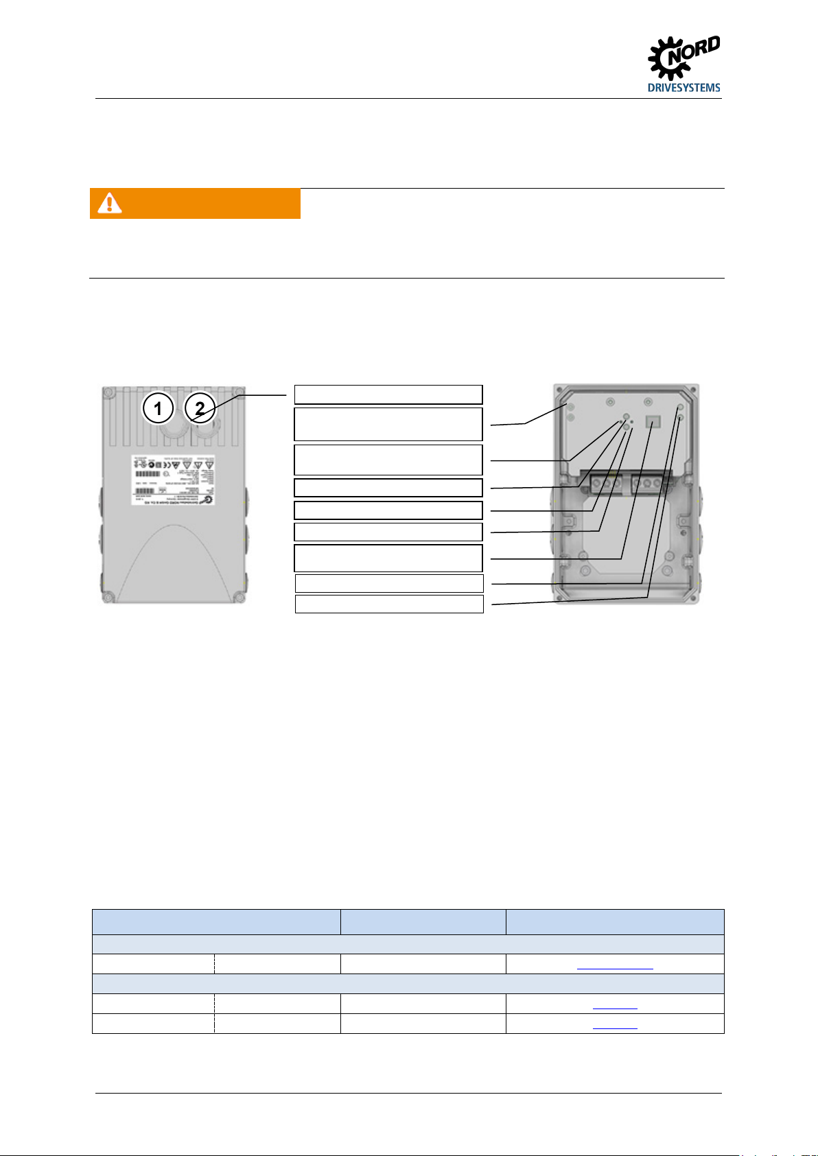
NORDAC START (SK 135E / SK 175E) – Users Manual for Motor Starters
Switch
Control and parametrisation units /(handheld)
SK CSX-3H
275281013
BU0040
PROFIBUS DP addressing
Status LED for bus system
(SK 175E only)
Potentiometer P1
Potentiometer P2
Device status LED (DS)
Diagnostic interface RJ12
(RS232)
Potentiometer P3
Potentiometer P4
Diagnostics openings
3 Display, operation and options
WARNING Electric shock
When devices are open, electrically conducting elements (e.g. connection terminals, connection cables, PCBs,
etc.) are freely accessible. These may be live, even if the device has been switched off.
• Avoid all contact.
The device can be basically started up without parameter adaptation, i.e. programming-technical aids.
4 potentiometers (P1 – P4) and a 4-pin DIP switch block (S1) are available for this. Access to P1 and
P2 takes place using the diagnostics opening in the centre. This is where the status LEDs of the
device are located. Potentiometers P3 and P4 and the PROFIBUS DP addressing (SK 175E-…-PBR
only) are accessible by removing the cover of the device.
(SK 175E-…-PBR only)
The SK 1x5E can be easily adapted to a wide range of requirements by using function-enhancing
modules for display, control and parametrisation.
Optionally available control devices from NORD or the free "NORDCON" PC software can be used for
targeted adaptation of individual parameters. The right-hand diagnostic connection must be opened to
access the diagnostic interface. Devices with an older manufacturing date (serial number (ID) "26P…"
or less) only have the diagnostic opening in the centre. The diagnostics interface is then only
accessible by removing the cover of the device.
3.1 Control and parametrisation options
Various control options are available that can be fitted directly to the device or in close proximity to it
and directly connected.
Parametrisation units also provide a facility for accessing the parametrisation of the device and
adapting it.
Designation Part Number Document
(attachment)
SK TIE4-SW T Switch "L-OFF-R" 275274701 TI 275274701
SimpleBox
SK PAR-3H
ParameterBox
54 BU 0135 en-4118
275281014 BU0040
Page 55
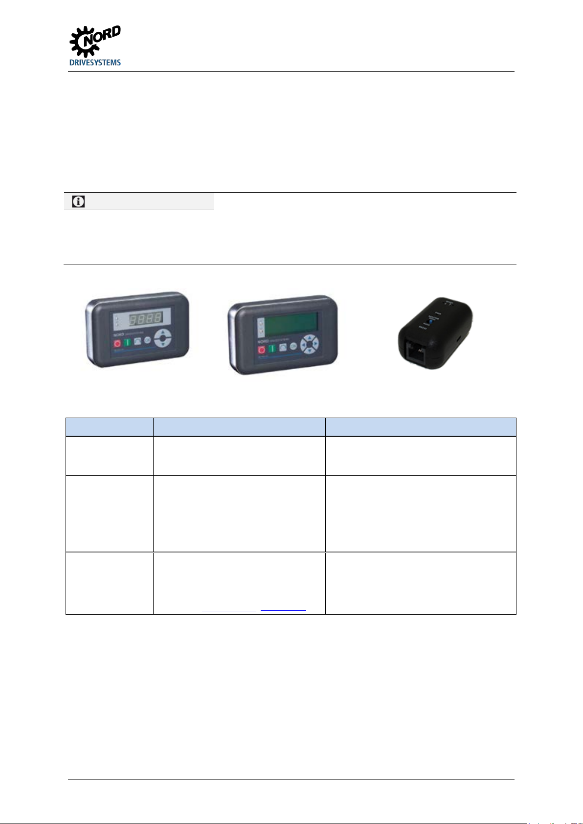
3 Display, operation and options
Information
Status LED DS
4-digit, 7-segment LED display, membrane key
4-line backlit LCD display, membrane
Connection extension for the conversion
3.1.1 Control and parametrisation units, use
Access to the parameters of the SK 1x5E can take place either using the NORD CON software or with
the aid of an optionally available SimpleBox or ParameterBox. Permanent parameter changes must be
saved in the Flash memory of the device using parameter P550.
A SimpleBox or ParameterBox cannot be connected directly to the device, but must be connected
using an RS 232 / RS 485 converter (SK TIE4-RS485-RS232, Part No. 275274603). When doing this
the parametrisation unit must be connected to the converter before making the connection to the
motor starter. The motor starter must be ready for operation when this takes place.
With active RS232 communication to the PC (NORD CON) or to a connected parametrisation unit, the status of
the device cannot be indicated via the LEDs. In this case, the "DS" LEDs signal that communication activity is
taking place by being permanently on in green. The red LED is then switched off.
The green LED can also be made to flash by adjusting potentiometer P1.
Figure 7: SK CSX-3H / SK PAR-3H / SK TIE4-RS485-RS232 (l-r)
Module Description Data
SK CSX-3H
(handheld SimpleBox)
SK PAR-3H
(handheld ParameterBox)
* Also required:
Converter
*)
*)
SK TIE4-RS485RS232
Used for commissioning, parametrisation,
configuration and control of the device.
Used for commissioning, parametrisation,
configuration and control of the device
(only in ControlBox mode) and its options
(SK xU4-…). Entire parameter data sets
can be stored.
of the RS485 signal of the parametrisation
units SK CSX-3H or SK PAR-3H to the
RS232 signal of the starter
Data sheet TI 275274603 (www.nord.com)
IP20
RJ12-RJ12 cable (connection to the device 1)
keyboard
Stores up to 5 complete parameter data sets
IP20
RJ12-RJ12 cable (connection to device)
USB cable (connection to PC)
IP20
Cable RJ12-RJ12 (connection to device /
option)
Part No. 275274603
BU 0135 en-4118 55
Page 56
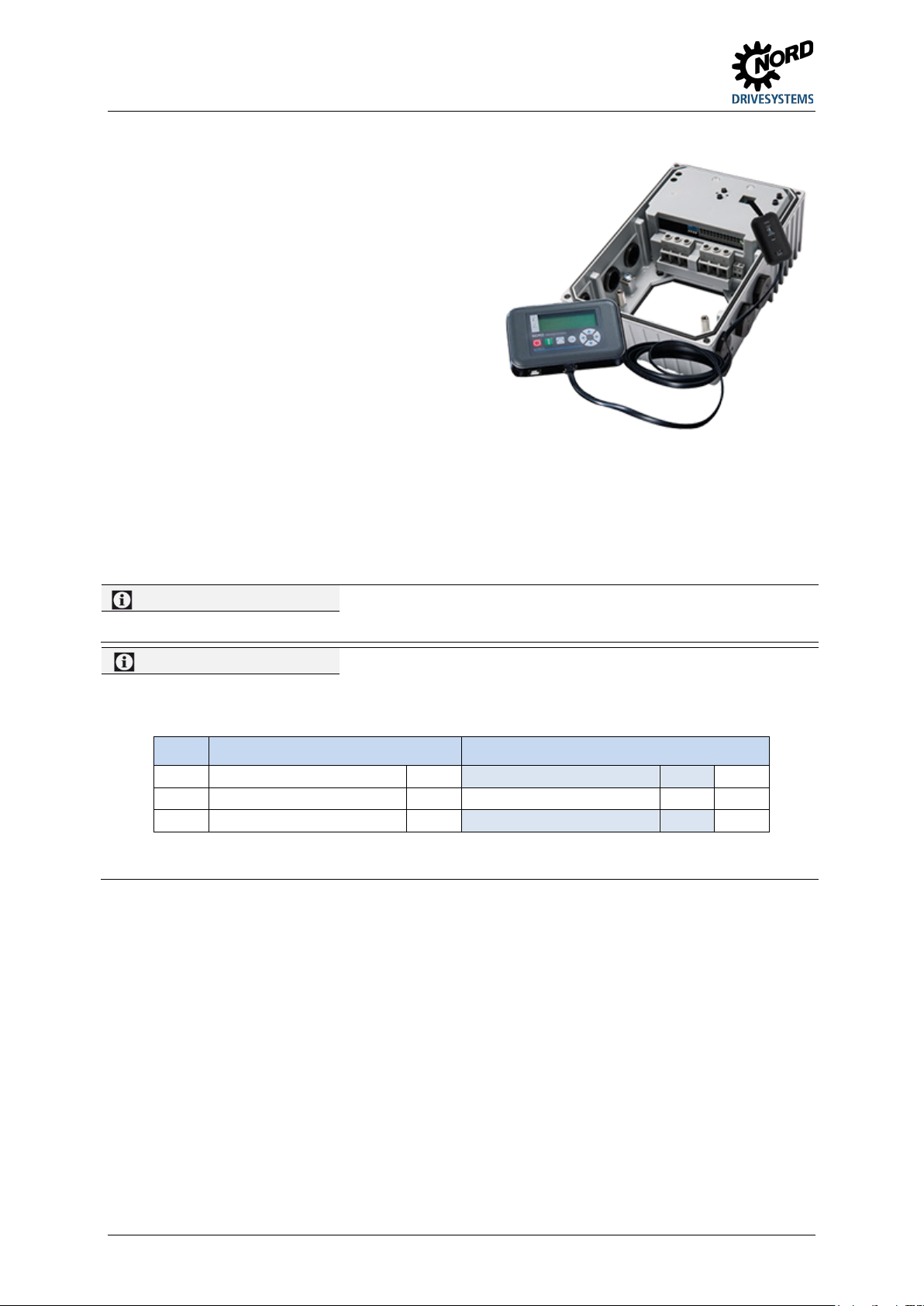
NORDAC START (SK 135E / SK 175E) – Users Manual for Motor Starters
Information
Diagnostic cap tightening torque
Information
Control with SK PAR-3H
2
1003 selection
ControlBox
o.k.
Connection to motor starter
1. Remove right-hand diagnostics glass (transparent
cable gland) of the RJ12 socket from the housing
cover, alternatively remove housing cover
(illustration on right)
WARNING: Electric shock possible from touching
conducting parts with device open!
2. Set DIP switch to Master RS 485 at converter
(SK TIE4-RS485-RS232)
3. Connect control and parametrisation unit to
converter
4. Check that the 24 V DC voltage supply at the
motor starter is switched on.
5. Connect converter with connected control and
parametrisation unit to diagnostics socket.
After completing commissioning, the power supply must be switched off again and the device correctly
closed off again (casing cover, diagnostics caps and cable glands) in order to restore operating safety
and the IP protection class).
The tightening torque for the transparent diagnostic caps (inspection glasses) is 2.5 Nm.
In order to be able to control the motor starter with the ParameterBox (SK PAR-3H) (Start / Stop), it must be put
into ControlBox Mode beforehand.
Step Menu item Selection
1 Display
3 P0 back
However, motor starter parametrisation can be carried out independently of the mode that has been selected.
o.k.
o.k.
56 BU 0135 en-4118
Page 57
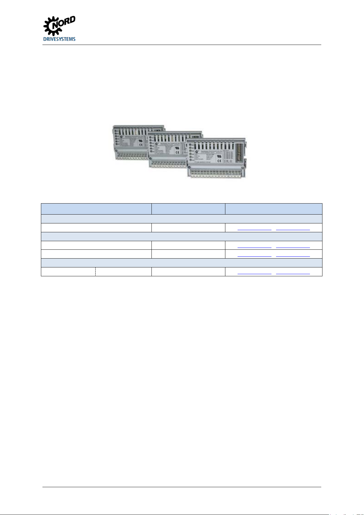
3 Display, operation and options
I/O expansions
Power supply
SK CU4-24V-123-B(-C)
275271108 / (275271608)
TI 275271108 / TI 275271608
Miscellaneous
*
All modules with designation –C have lacquered PCBs so that they can be used in IP6x devices.
3.2 Optional modules
3.2.1 Internal customer interfaces SK CU4-… (installation of modules)
Internal customer units allow the scope of functionality of the devices to be extended without changing
the physical size thereof. The device provides an installation location for the installing an appropriate
option. If other option modules are required the external technology units must be used for these
( Section 3.2.2 "External technology units SK TU4-… (module attachment)").
Figure 8: internal customer units SK CU4 … example
Name *) Part Number Document
SK CU4-REL(-C) 275271011 / (275271511) TI 275271011 / TI 275271511
SK CU4-24V-140-B(-C) 275271109 / (275271609) TI 275271109 / TI 275271609
SK CU4-FUSE(-C)
Fuse module
275271122 / (275271622) TI 275271122 / TI 275271622
BU 0135 en-4118 57
Page 58
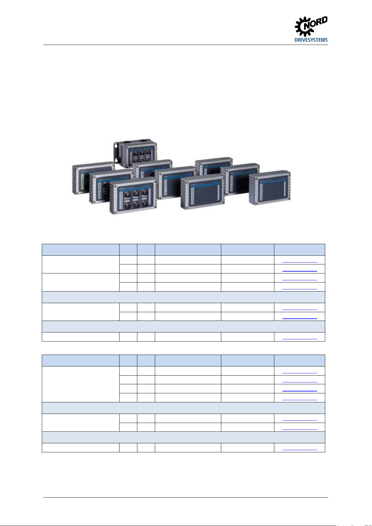
NORDAC START (SK 135E / SK 175E) – Users Manual for Motor Starters
Power supply 24V / 1~ 230V
X SK TU4-24V-123-B
275 281 108
TI 275281108
Power supply 24V / 1~ 400V
X SK TU4-24V-140-B
275 281 109
TI 275281109
Connection unit
X SK TI4-TU-NET
275 280 100
TI 275280100
Maintenance switch
X SK TU4-MSW
275 281 123
TI 275281123
X SK TU4-MSW-C
275 281 173
TI 275281173
X SK TU4-MSW-RG-C
275 281 175
TI 275281175
Connection unit
X SK TI4-TU-MSW
275 280 200
TI 275280200
X SK TI4-TU-MSW-C
275 280 700
TI 275280700
Wall-mounting kit
X X SK TIE4-WMK-TU
275 274 002
TI 275274002
3.2.2 External technology units SK TU4-… (module attachment)
External technology units allow the scope of functionality of the devices to be extended in a modular
way.
Depending on the type of module, different versions are available (differentiated according to IP
protection class, with/without connector etc.). They can be fitted directly to the device using the
relevant connection unit or in the vicinity of the device using an optional wall mounting kit.
Each SK TU4-… technology unit requires an associated SK T14-TU-… connection unit.
Figure 9: external technology units SK TU4-… (example)
Type IP55 IP66 Designation Part Number Document
X SK TU4-24V-123-B-C 275 281 158 TI 275281158
X SK TU4-24V-140-B-C 275 281 159 TI 275281159
Required accessories (each module must have an associated connection unit)
X SK TI4-TU-NET-C 275 280 600 TI 275280600
Optional accessories
Wall-mounting kit X X SK TIE4-WMK-TU 275 274 002 TI 275274002
Table 7: external modules with SK TU4-24V- … power supply
Type IP55 IP66 Designation Part Number Document
X SK TU4-MSW-RG 275 281 125 TI 275281125
Required accessories (each module must have a matching connection unit)
Table 8: external modules – maintenance switch SK TU4-MSW- …
58 BU 0135 en-4118
Optional accessories
Page 59
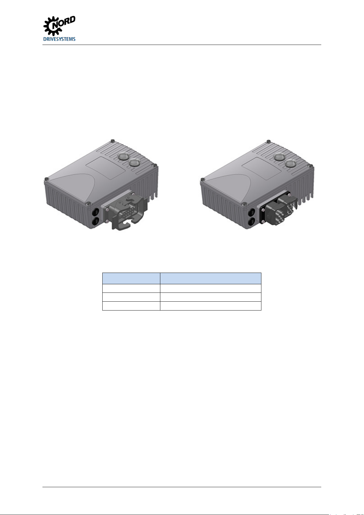
3 Display, operation and options
… - LA
Power output
3.2.3 plug connectors
The use of optionally available plug connectors for power and control connections not only makes it
possible to replace the drive unit with almost no loss of time in case of servicing, but also minimises
the danger of installation errors when connecting the device. The most common plug connector
versions are summarised below. The possible installation locations on the device are listed in section
2.2 "Installation of optional modules".
3.2.3.1 Plug connectors for power connections
Various connectors are available for the motor or mains connection.
Figure 10: Examples of devices with connectors for connecting the power
3 different connections are available, which can also be combined (example "-LE-MA"):
Mounting version Meaning
… - LE Power input
… - MA Motor output
BU 0135 en-4118 59
Page 60

NORDAC START (SK 135E / SK 175E) – Users Manual for Motor Starters
Power input
500 V, 16 A
SK TIE4-HANQ8-K-LE-MX
275 135 030
TI 275135030
Power input
500 V, 16 A
SK TIE4-HAN10E-M2B-LE
275 135 000
TI 275135000
Power input
690 V, 20 A
SK TIE4-QPD_3PE-K-LE
275 274 125
TI 275274125
Power input +
400 V, 16 A
SK TIE4-2HANQ5-K-LE-LA
275 274 110
TI 275274110
Power output
500 V, 16 A
SK TIE4-HANQ8-K-LA-MX
275 135 040
TI 275135040
Motor output
500 V, 16 A
SK TIE4-HANQ8-K-MA-MX
275 135 050
TI 275135050
Information
Looping of the mains voltage
Various M12 round plug connectors are available as
screwed state. Similarly to the use of coding pins /
grooves, the colour coding of the connectors (plastic
on functional
requirements and is intended to avoid erroneous
Connector (selection)
Type Data Designation Material no. Document
Power input 500 V, 16 A SK TIE4-HAN10E-M1B-LE 275 135 070 TI 275135070
Power input 630 V, 16 A SK TIE4-NQ16-K-LE 275 274 133 TI 275274133
power outlet
Power input +
motor outlet
Power output 500 V, 16 A SK TIE4-HAN10E-M2B-LA 275 135 010 TI 275135010
Motor output 500 V, 16 A SK TIE4-HAN10E-M2B-MA 275 135 020 TI 275135020
600 V, 16 A SK TIE4-2HANQ5-M-LE-MA-001 275 274 123 TI 275274123
The permissible current load for the connection terminals, plugs and supply cables must be observed when
looping the mains voltage. Failure to comply with this will result in thermal damage to current-carrying modules
and the immediate vicinity thereof.
The use of a SK CU4-FUSE(-C) is recommended for internal device protection, which must be
incorporated directly in the power supply cable of the device concerned. This ensures that in the event
of a fault, only the defective device is disconnected from the power and not the entire power supply
line.
3.2.3.2 Plug connectors for control connection
flanged plugs or flanged sockets. The plug connectors
are intended for installation in an M16 cable gland of the
device, or in an external technology unit. The protection
class (IP67) of the plug connector only applies in the
unit inside and cover caps) is based
operation.
Suitable expansion and reducer adapters are available
for installation in M12 and M20 cable glands.
60 BU 0135 en-4118
Page 61
3 Display, operation and options
Sensors / actuators
Socket
SK TIE4-M12-INI
275 274 503
TI 275274503
Initiators and 24 V
Connector
SK TIE4-M12-CAO
275 274 516
TI 275274516
AS Interface – Aux
Connector
SK TIE4-M12-ASI-AUX
275 274 513
TI 275274513
Connector (selection)
Type Version Designation Part Number Document
Power supply Connector SK TIE4-M12-POW 275 274 507 TI 275274507
AS Interface Connector SK TIE4-M12-ASI 275 274 502 TI 275274502
PROFIBUS (IN + OUT) Plug connector
+ socket
SK TIE4-M12-PBR 275 274 500 TI 275274500
BU 0135 en-4118 61
Page 62
NORDAC START (SK 135E / SK 175E) – Users Manual for Motor Starters
hazard the drive or drive chain must be secured against unexpected movements
Information
Hardware configuration
and internal
of the motor starter, the parameter values must be
4 Commissioning
WARNING Unexpected movement
Connection of the supply voltage may directly or indirectly set the drive unit into motion. This may cause an
unexpected movement of the drive unit and the machine which is connected to it. This unexpected movement
may cause severe or fatal injuries and/or material damage.
Unexpected movements may be due to several causes, e.g.
• Parameterisation of an "automatic start",
• Incorrect parameterisation,
• Control of the device with an enabling signal from a higher level control unit (via IO or bus signals),
• Incorrect motor data,
• Release of a mechanical holding brake,
• External influences such as gravity or other kinetic energy which acts on the drive unit.
To avoid any resulting
(mechanical blocking and/or decoupling, provision of protection against falling, etc.) In addition, it must be
ensured that there are no persons within the area of action and the danger area of the system.
4.1 Factory settings
All motor starters supplied by Getriebebau NORD are pre-programmed with the default setting for
standard applications with 4-pole standard motors (same voltage and power). The nominal current of
the motor (see motor type plate, for example) can be set for the respective motor circuit using
potentiometer P1, which has priority in the factory setting or the as-delivered condition. If parameter
P130=1, the nominal current of the motor must be set in parameter P203 "Rated motor current".
It must be ensured that the hardware can essentially be configured mechanically using DIP switch block S1 and
potentiometers P1 ... P4 or alternatively by adapting individual parameters. The decision concerning this is made
by setting parameter P130 ( Section 4.2.2 "Configuration").
4.2 Starting up the device
The motor starter can be started up in various ways:
For simple applications (e.g conveyor applications) by means of the DIP switches (S1) integrated
a)
in the device (internal), the two externally accessible potentiometers P1 and P2
potentiometers P3 and P4.
b) By adapting parameters using the control and parametrisation unit (SK CSX-3H or SK PAR-3H) or
the NORD CON PC - supported software.
Attention must be paid to the setting of parameter P130 when doing this. The parameter settings
are only effective if P130 = 1!
After completing the parametrisation
transferred from the RAM memory to the Flash memory of the device ( P550)! Otherwise the
settings that have been made will be lost again when the device is shut off.
Note: Flash memory! Approximately 100 memory cycles are possible!
62 BU 0135 en-4118
Page 63
4 Commissioning
1.
Parameter source
P130 = 0
{ 0 }
P130 = 1
{ 0 } 2.
3.
Locking time
P2
-1)
P570
{ 0.5 } 4.
6.
Run time
P103
{ 1 } 7.
8.
Phase sequence detection
S1-DIP2
{ OFF }
P581
{ 0 } 9.
4.2.1 Connection
In order to provide basic operational capability, after the device has been attached to the motor or the
wall mounting kit, the power and motor lines must be connected to the relevant terminals
( Section 2.3.2 "Electrical connection of power unit").
It is also essential for the device to be provided with a 24 V DC control voltage.
Information
Control voltage
The 24 V control voltage that is required can be implemented by means of an integrated (SK CU4-24V-…) or
external (SK TU4-24V-…) optional mains module or a comparable 24 V DC power source ( Section 2.3.3
"Electrical connection of the control unit").
4.2.2 Configuration
The device can be configured for the majority of operating modes by setting potentiometers (P1-P4)
and DIP switches (S1). For extended functions or for diagnostic purposes it may be necessary to
adjust or view individual parameters.
The basic steps for successful start-up of the motor starter are listed in the following. To begin with, it
must be decided whether the start-up is to take place via DIP switches and the potentiometers, or
exclusively by means of parameter setting.
The software adaptations that are made via the parameters are only taken into consideration if
parameter P130 is set to a value of ( 1 ).
Any parameters that are not listed here always have an influence on the functionality of the motor
starter, irrespective of the setting of parameter P130. However, they always remain in the factory
setting at P130 = "0".
Step Commissioning via
Switches / potentiometers
(Hardware adaptations)
Element Default Parameter Default
Parameter settings
(Software adaptation)
Rated motor current P1 -1) P203 { 3 }
Start voltage P3 -1) P210 { 50 }
5. Acceleration time
P4 -1)
P102 { 1 }
Automatic starting S1-DIP1 { OFF } P428 { 0 }
Switch-off mode S1-DIP3/4 { OFF/OFF } P108 { 2 }
10. Save data permanently P550 = 12) { 0 }
1) For technical manufacturing reasons, no clear factory settings (defaults) can be stipulated.
After completing the software adaptations, the data must be transferred from the RAM memory of the device to the Flash memory in
2)
order to retain them permanently. Otherwise the data changes will be lost when the device is switched off.
Table 9: Configuration - comparison of hardware and software adaptation
BU 0135 en-4118 63
Page 64
NORDAC START (SK 135E / SK 175E) – Users Manual for Motor Starters
Basic parameters
P102 … P103
Start-up and shut-down time
Factory setting:
P130
Parameter source
P130=0 (Factory setting):
Motor data
P203
Rated motor current
Factory setting:
P210
Start voltage
Factory setting:
4.2.2.1 Parametrisation
The use of a control and parametrisation unit (SK CSX-3H / SK PAR-3H) or the NORDCON software
is required to adapt the parameters. The most important parameters are shown in the following,
depending on the setting of parameter P130:
Parameter group Parameter numbers Functions Comments
Value of potentiometer P4
P108 Switch-off mode Factory setting:
Value of DIP switch S1-
DIP3/4
P130=0 Potentiometer/
Switch
P130=1 Flash memory
Potentiometers (P1-P4) and
DIP switch (S1) effective
P130=1:
Parameter settings effective
Value of P1
Value of potentiometer P3
Control terminals P420, P434 Digital inputs and outputs Factory setting:
See description of
parameter(s)
Additional
parameters
Table 10: Parameters and functions depending on P130
P570 Locking time Factory setting:
Value of potentiometer P2
64 BU 0135 en-4118
Page 65
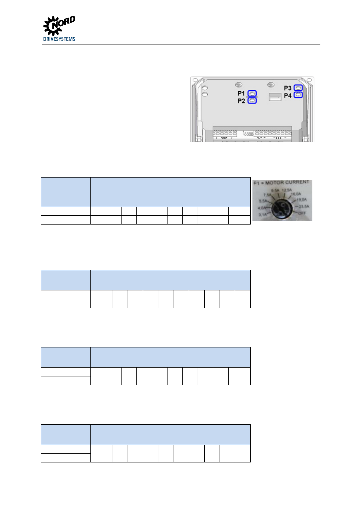
4 Commissioning
Basic settings for the operation of the motor
starter can be made using potentiometers P1 to
latching and each one has
scale values. The potentiometers are provided
at the
SK 1x5E-301-…
0.9
1.3
1.7
2.3
3.1
4.0
5.5
7.5
9.5
OFF 1)
1)
I2t monitoring deactivated
Figure:
SK 1x5E-301-…
1)
Without locking time
SK 1x5E-751-…
SK 1x5E-301-…
1)
Soft start disabled
4.2.2.2 Potentiometers P1 to P4
P4. They are non10
with non-linear characteristic curves
software side.
Potentiometer P1
Nominal motor current setting
Device type
(Setting in accordance with motor type plate)
Scale value
[A]
SK 1x5E-751-… 3.1 4.0 5.5 7.5 9.5 12.5 16.0 19.0 23.5 OFF 1)
Potentiometer P2
Locking time setting
Device type
SK 1x5E-751-…
OFF 1) 0.1 0.2 0.4 0.8 1.6 3.2 6.4 12.8 25.6
Scale value
[s]
Potentiometer P3
Starting torque setting (voltage)
Device type
SK 1x5E-301-…
10 15 20 25 30 40 50 60 80 100
Scale value
[%]
P1 of a 7.5 kW motor starter
Potentiometer P4
Start-up and shut-down time setting
Device type
SK 1x5E-751-…
OFF 1) 0.1 0.2 0.4 0.8 1.6 3.2 6.4 12.8 25.6
BU 0135 en-4118 65
Scale value
[s]
Page 66
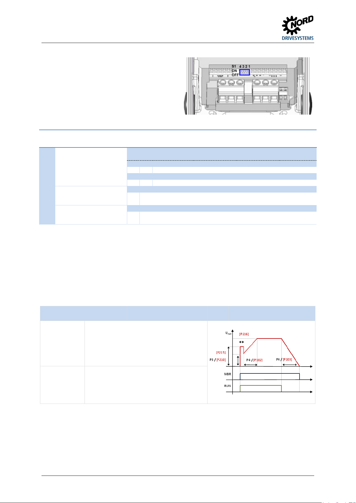
NORDAC START (SK 135E / SK 175E) – Users Manual for Motor Starters
The basic functionality of the motor starter is set
delivered condition, all four DIP switches
Switch on
1. P3 and P210 determine the starting voltage
Switch off
1. P4 and P103 determine the duration for which
No.
DIP-No
4 3
0 0 Switch-off mode 1 (factory setting)
I 0 Switch-off mode 2
0 I Switch-off mode 3
I I Switch-off mode 4
0
Phase sequence according to mains connection(factory setting)
Phase sequence according to required direction of rotation,
automatic detection of phase sequence
0
Enable with flank (factory setting)
Enable with level
ATTENTION, drive can start off immediately!
4.2.2.3 DIP switches (S1)
using DIP switch (S1).
In the asare in position "0" ("OFF").
Bit DIP switch (S1)
4/3
Switch-off mode
3/2
2
Phase sequence
2
1
2
detection
I
1
Automatic starting
0
2
I
4.2.2.4 Overview of switch-off modes
The switch-off mode determines the start-up and shut-down behaviour of the drive.
Parameter P130 determines whether the switch-off mode should be set by means of hardware
adaptation (DIP switch (S1), potentiometer (P1-P4)) or software adaptation (parametrisation of P108).
The main modes of behaviour can be set by means of hardware adaptation (factory setting).
Other settings can be made by means of parameter adaptations if there is a need for further
optimisation.
Switch-off mode 1
(Set enable)
(starting torque) that is applied to the motor.
DIP3/4: OFF/OFF
(Factory setting)
2. The brake opens.
3. P4 and P102 determine the duration for which
the voltage is continuously increased until the
full voltage (100 %) is reached.
(Cancellation of
release)
the voltage is continuously reduced from
1)
100 % to 0 %.
2. The brake is applied when the voltage
reaches "0 %" or after P107 has elapsed.
1) For technical reasons, the motor starter switches immediately to 0 % when approx. 10 % of the starting voltage is reached.
or P108 = 0
66 BU 0135 en-4118
Page 67
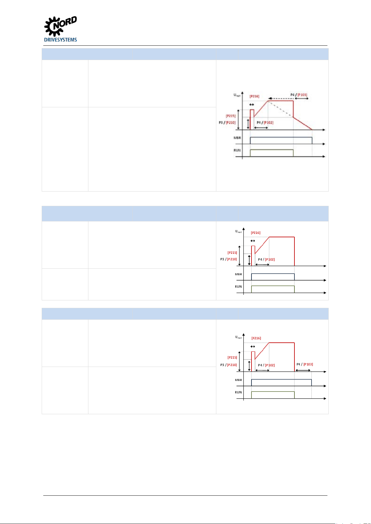
4 Commissioning
DIP3/4: OFF/ON
or
P108 = 1
Switch on
1. P3 and P210 determine the starting voltage
Switch off
1. P3 and P210 determine the voltage (torque)
DIP3/4
P108
Switch on
1. P3 and P210 determine the starting voltage
Switch off
1. The motor is switched off immediately
DIP3/4
P108
Switch on
1. P3 and P210 determine the starting voltage
Switch off
1. The motor is switched off immediately
Switch-off mode 2
(Set enable)
(starting torque) that is applied to the motor.
2. The brake opens.
3. P4 and P102 determine the duration for which
the voltage is continuously increased until the
full voltage (100 %) is reached.
(Cancellation of
release)
to which the motor controller immediately
drops.
2. P4 and P103 determine the duration for which
the voltage would be continuously reduced
from 100 % to 0 %. However, only the part of
the duration that is needed to reduce from the
set starting voltage (P3 or P210) to 0 % is
1)
used.
3. The brake is applied when the voltage
reaches "0 %" or after P107 has elapsed.
1) For technical reasons, the motor starter switches immediately to 0 % when approx. 10 % of the starting voltage is reached.
Switch-off mode 3
(Set enable)
: ON/OFF or
(starting torque) that is applied to the motor.
= 2
(Factory setting)
2. The brake opens.
3. P4 and P102 determine the duration for which
the voltage is continuously increased until the
full voltage (100 %) is reached.
(Cancellation of
release)
(voltage "0 %") and runs down to a standstill.
2. The brake is applied when the voltage
reaches "0 %" or after P107 has elapsed.
Switch-off mode 4
(Set enable)
(starting torque) that is applied to the motor.
2. The brake opens.
3. P4 and P102 determine the duration for which
the voltage is continuously increased until the
full voltage (100 %) is reached.
(Cancellation of
release)
(voltage "0 %") and runs down to a standstill.
2. P4 and P103 determine the duration of the
delay, during which the brake is not yet
applied.
3. The brake is applied.
: ON/ON or
= 3
BU 0135 en-4118 67
Page 68
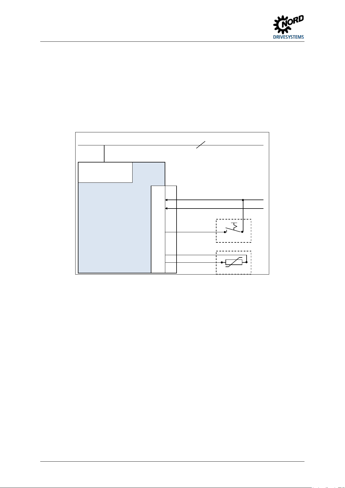
NORDAC START (SK 135E / SK 175E) – Users Manual for Motor Starters
Motor starter
SK 1x5E
-...
X5
44
40
.
.
21
22
.
38
39
L1 - L2 - L3 PE
200 … 500V
24V=
GND
3~ 200 … 500V + PE
Switch S1
Motor PTC
4.2.3 Commissioning examples
All SK 1x5E devices can basically be operated in the condition in which they are delivered.
If an automatic start-up is required when "Mains on" takes place (depending on setting P130), either
adapt parameter (P428) or set DIP switch S1-DIP1 = ON.
The PTC input must be bypassed, if a motor with PTC is not available.
The motor starter must be provided with an external 24 V DC control voltage.
Minimal configuration
Motor start via switch
Motor start with direction of rotation "right":
• If the switch is set to "On" and 24 V DC is therefore present at digital input 1 (terminal 21), the
Motor start with direction of rotation "left":
• If the switch is set to "On" and 24 V DC is therefore present at digital input 2 (terminal 22), the
Motor start via mains voltage "ON"
DIP switch S1 / DIP1 = ON corresponds to automatic start
Motor start with direction of rotation "right":
• If the mains voltage is set to "On" and 24 V DC is therefore present at digital input 1 (terminal 21),
Motor start with direction of rotation "left":
• If the mains voltage is set to "On" and 24 V DC is therefore present at digital input 2 (terminal 22),
68 BU 0135 en-4118
motor starter starts to operate in the "right" (clockwise) direction.
motor starter starts to operate in the "left" (anticlockwise) direction.
the motor starter automatically starts to operate in the "right" (clockwise) direction.
the motor starter automatically starts to operate in the "left" (anticlockwise) direction.
Page 69
4 Commissioning
Standard slave 1 (Address 6)
Standard slave 1 (Address 6)
A/B slave 1 (Address 7A)
Standard slave 2 (Address 7)
A/B slave 2 (Address 7B)
A/B slave 1 (Address 7B)
Standard slave 2 (Address 8)
Standard slave 3 (Address 8)
4.3 AS Interface (AS-i)
This section is only relevant for device of type SK 175E-...-ASI.
4.3.1 The bus system
General information
The Actuator-Sensor-Interface (AS interface) is a bus system for the lower field bus level. It is fully
defined in the AS interface Complete Specification and standardised as per EN 50295, IEC62026.
The transmission principle is a single master system with cyclical polling. Since Complete
Specification V2.1, a maximum of 31 standard slaves which use device profile S-7.0. or 62 A/B
slaves that use device profile S-7.A. can be operated on a non-shielded two-wire cable up to 100 m in
length with any network structure.
The number of possible slave subscribers can be doubled by means of double assignment of
addresses 1-31 and designation "A Slave" or "B Slave". A/B Slaves are designated by the ID code A,
and therefore can be uniquely identified by the Master.
Devices with slave profiles S-7.0 and S-7.A can be jointly operated within an AS-i network as of
version 2.1 (Master profile M4) with observance of the allocation of addresses (see example).
Permissible Not permissible
Addressing is implemented via the master, which can also provide other management functions, or via
a separate addressing device.
Device-specific information
The transfer of the 4-bit reference data (in each direction) is performed with effective error protection
for standard slaves with a maximum cycle time of 5 ms. Due to the correspondingly higher number of
participants, for A/B slaves the cycle time (max. 10 ms) is doubled for data which is sent from the
slave to the master. Extended addressing procedures for the transmission of data to the slave also
cause an additional doubling of the cycle time to max. 21 ms.
The yellow AS interface cable supplies data and energy.
The motor starter is configured in such a way that no additional auxiliary voltage has to be connected.
However, by adapting a jumper it is possible to configure the motor starter in such a way that the
yellow AS-i cable is only used for data transmission and supplies the AS-i bus. The device itself and
sensors and the like that are connected via the device are then provided with an auxiliary voltage
(24 V DC) by a second two-wire cable (black). When doing this it is essential to provide the supply
via a protective low voltage (PELV - Protective Extra Low Voltage).
4.3.2 Features and technical data
The device can be directly integrated in an AS interface network is parametrised in its factory settings
so that the most frequently used AS-i functionality is available immediately. Only adaptations for
application-specific functions of the device or the bus system, the addressing and proper connection of
the supply, BUS, sensor and actuator cables need to be carried out.
BU 0135 en-4118 69
Page 70
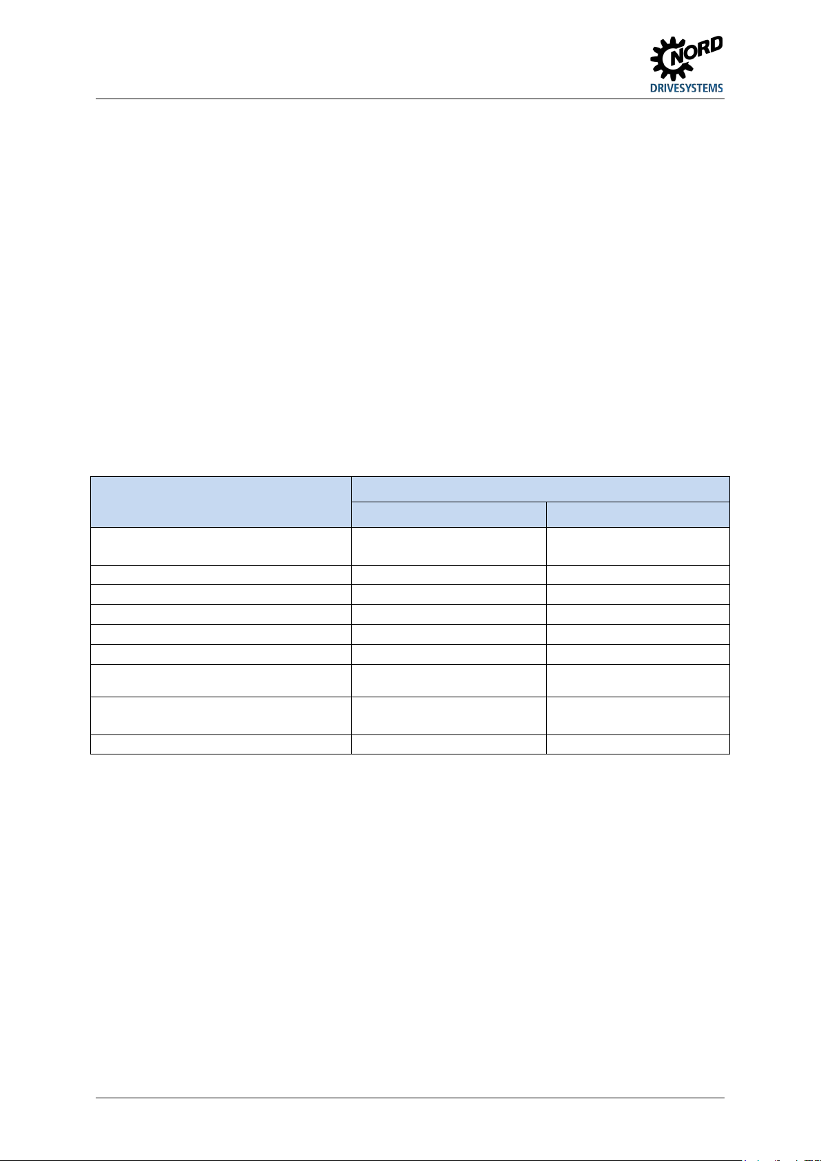
NORDAC START (SK 135E / SK 175E) – Users Manual for Motor Starters
26.5 – 31.6 V DC,
26.5 – 31.6 V DC,
AUX supply (black cable)
24 V DC ± 25 %, max. 400 mA
Connection not permitted
I/O-Code 7 7
External ID Code 1 / 2
7
7
1A – 31A and 1B - 31B
1A – 31A and 1B - 31B
Slave Master ≤ 10 ms
Slave Master ≤ 10 ms
Quantity of (BUS I/O)
4I / 4O
4I / 4O
Features
• Electrically isolated bus interface
• Status display (1 LED)
• Configuration, optionally via
– integrated potentiometers and DIP switches
– or by means of parametrisation
• 24 V DC supply of integrated AS-i module via yellow AS-i cable
• 24 V DC supply to the motor starter
– via yellow AS-i cable (factory setting)
– or separately via black cable or another 24 V DC source – e.g. SK xU4-24V-… power supply (configurable
with jumpers)
• Connection to device
– via terminal strip
– or via M12 flanged connectors
Technical data for AS interface
Designation
Value
Jumper position "AUX" Jumper position "AS-I"
Supply via AS-i (yellow cable)
max. 25 mA
max. 240 mA 1)
Slave profile S-7.A S-7.A
ID Code A A
Address
Cycle time
1) Of which max. 165 mA is for peripherals (initiators, connected parametrisation tool, actuators)
(Delivery condition: 0A)
Master Slave ≤ 21 ms
(Delivery condition: 0A)
Master Slave ≤ 21 ms
4.3.3 Bus structure and topology
The AS Interface network must be set up in any form (line, star, ring and tree structure) and is
managed by an AS interface master as the interface between the PLC and slaves. Additional slaves
can be added to an existing network at any time, up to a limit of 31 standard slaves or 62 A/B slaves.
The slaves are addressed by the master or an appropriate addressing device.
An AS-i master communicates independently and exchanges data with the connected AS-i slaves.
Normal power units may not be used in the AS interface network. Only a special AS interface power
unit may be used for the power supply for each AS interface connector. This AS interface power
supply is directly connected to the yellow standard cable (AS-i(+) and AS-i(-) cable) and should be
positioned as close as possible to the AS-i master in order to keep the voltage drop small.
In order to avoid problems, the PE connection of the AS interface power supply (if present) must
be earthed.
The brown AS-i(+) and the blue AS-i(-) wire of the yellow AS interface cable must not be earthed.
70 BU 0135 en-4118
Page 71
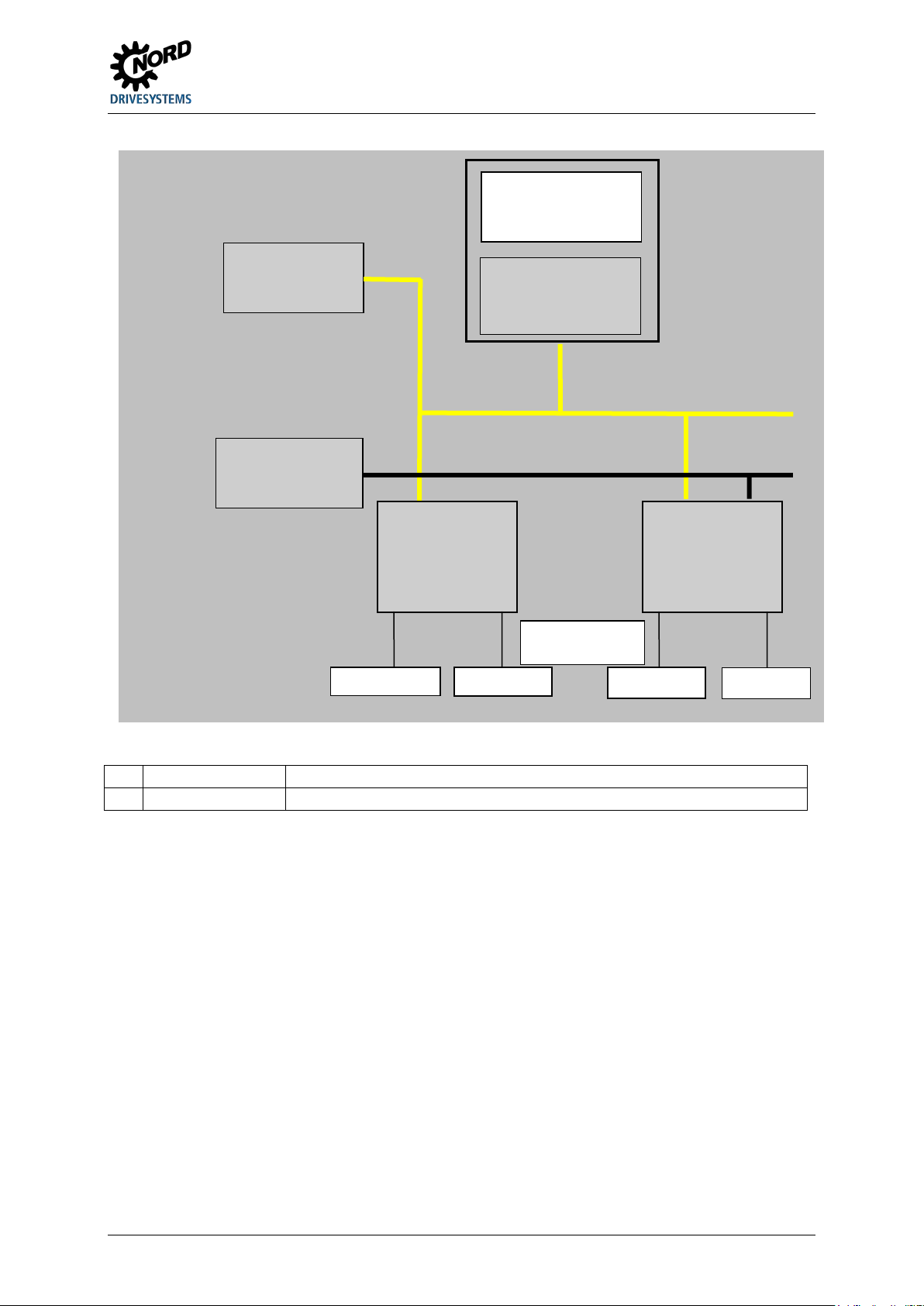
4 Commissioning
1)
SK 175E-…-ASI
Device with jumper position AS-I
Sensors
Actuators
Sensors
observe max.
power load
AS-i AS-i
AUX
AS interface
yellow cable
Actuators
24 V auxiliary supply,
Controller /
automation unit
AS interface
power unit
AS interface
master
24 V power supply
black cable
for auxiliary energy
AS interface
Slave 1)
AS interface
Slave 2)
2) SK 175E-…-ASI Device with jumper position AUX (separate 24 V DC supply for AS-i and motor starter)
BU 0135 en-4118 71
Page 72
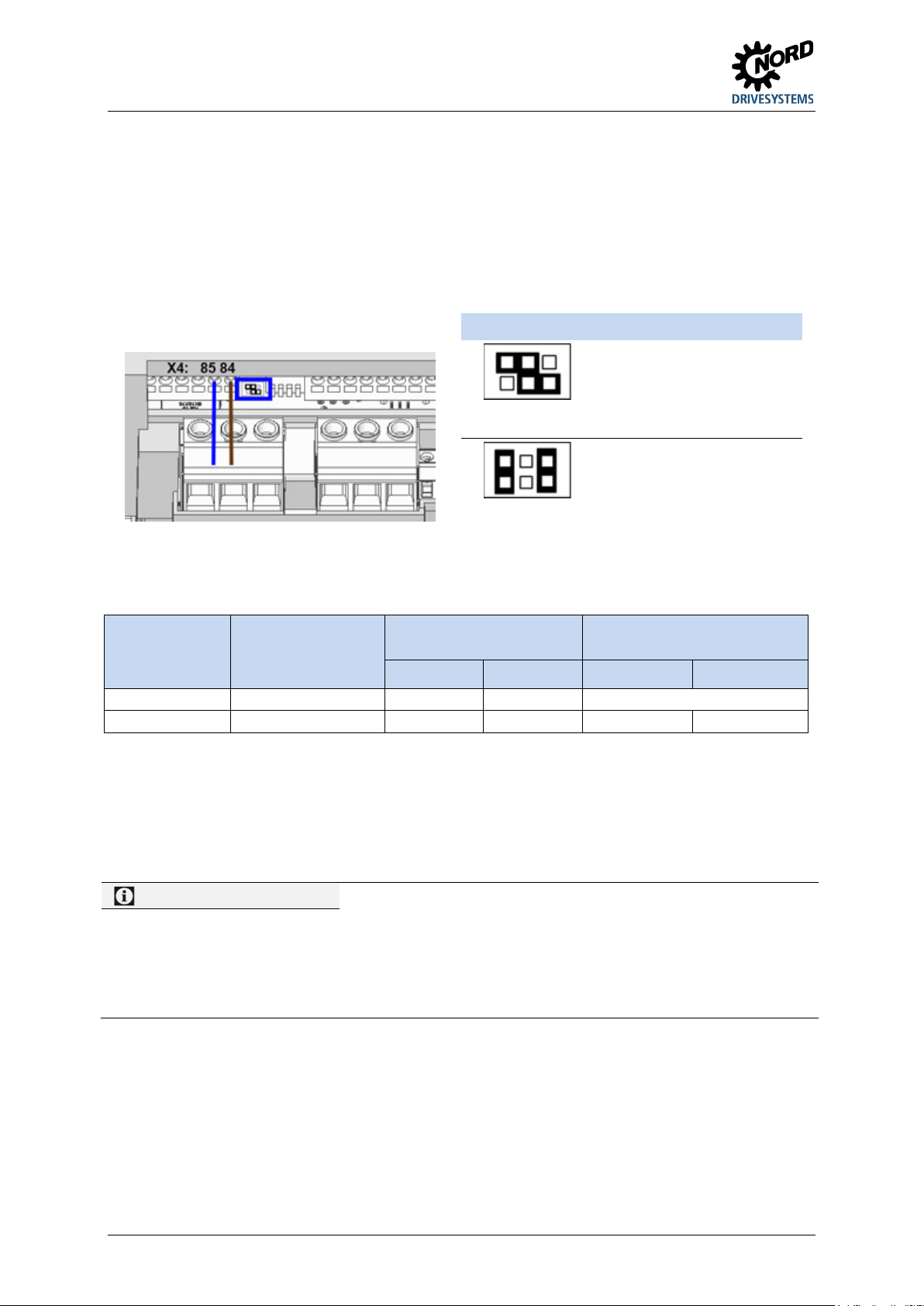
NORDAC START (SK 135E / SK 175E) – Users Manual for Motor Starters
The AS-i interface and the
SK 175E-…-ASI
AS-I
84
85
Information
24 V DC / AS interface
4.3.4 Commissioning
4.3.4.1 Connection
Connection of the AS interface cable (yellow) is made via terminals 85/85 of the terminal strip and can
optionally be made to an appropriately labelled M12 flange plug connector (yellow)
Details of control terminals ( Section 2.3.3 "Electrical connection of the control unit")
Details of connector ( Section 3.2.3.2 "Plug connectors for control connection")
Jumper position Meaning
The AS-i module is supplied via
the yellow AS-i cable and the
motor starter separately via the
AUX
AS-I
Factory setting
black cable (PELV).
device are both supplied via the
AS-i yellow cable. A separate
supply to the motor starter is
not permitted.
Figure 11: AS-i, connecting terminals and jumper position (example of "AUX" position)
Type Jumper position
AS interface connection
Control voltage connection
AUX cable of a PELV
AS-i(+) AS-i(-) 24 V DC GND
Connection not permitted!
SK 175E-…-ASI AUX 84 85 44 40
Table 11: AS interface, connection of signal and supply cables
In order to ensure that proper potential equalisation takes place, the connection of a second
earthing line is recommended. This must be connected to the PE connection of the device.
If the AS interface ("yellow cable") is not used, the normal connection requirements for the device
apply ( Section 2.3.3 "Electrical connection of the control unit").
If the yellow AS interface cable and jumper position AS-I are used:
– no voltage source may be connected to terminals 44/40,
– the device is supplied via the yellow AS-I cable,
– the supply voltage (24 V DC) for the use of the digital inputs or other external peripherals (e.g. actuators)
can be obtained from terminals 43/40. The permissible total current for this is limited to 165 mA!
72 BU 0135 en-4118
Page 73
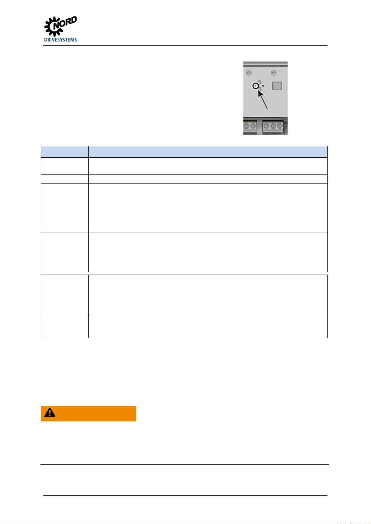
4 Commissioning
green ON
• Normal operation (AS interface active)
red ON
• No exchange of data
Alternately
• Peripheral error
1)
Switch-on frequency per second, example: 2 Hz = LED 2 x per second "On"
4.3.4.2 Displays
The status of the AS interface is signalled by a multicolour AS-i LED.
AS-i LED Meaning
OFF • No AS interface voltage to the module
• Connections not connected or exchanged
– Slave address = 0 (slave still in factory setting)
– Slave not in LPS (list of planned slaves)
– Slave with incorrect IO/ID
– Master in STOP mode
– Reset active
flashing
red / green
– Control unit in device not starting
(AS-i voltage too low or control unit defective)
Flashing
1)
(2 Hz)
Alternately
flashing
• No exchange of data
– Slave address = 0 (slave still in factory setting)
red / yellow
Flashing
(2 Hz) 1)
red
• EMC / Hardware error
Flashing
(2 Hz) 1)
4.3.4.3 Configuration
The most important functionality is assigned via the arrays [-04] … [-07] of parameter (P420) and via
the arrays [-01] … [-02] of parameter (P434).
Bus I/O bits
WARNING
Unexpected movement due to automatic starting
In the event of a fault (communication interrupted or bus cable disconnection, the device automatically switches
off, since the device enable is no longer present.
Restoration of communication may result in an automatic start and therefore, unexpected movement of the drive
unit. To prevent any hazard, a possible automatic start must be prevented as follows:
• If a communication error occurs, the bus master must actively set the control bits to "zero".
BU 0135 en-4118 73
Page 74
NORDAC START (SK 135E / SK 175E) – Users Manual for Motor Starters
Bit 1
Enable left
0 1
Field of rotation right present at motor
Bit 3
Release brake manually 2)
1 1 Motor is switched off
Bit 1
Operation (status bit 1)
0 1
Standby (motor stationary)
Bits 2 and 3 are directly coupled to digital inputs 3 and
The device is equipped with two additional digital inputs for connecting initiators. However, there are
no optional outputs for connecting actuators which are operated directly via the BUS. The following
connections are each provided for four reference data bits:
BUS-IN Function (P420[-04…-07])
Status
Bit 1 Bit 0
Bit 0 Enable right 0 0 Motor is switched off
Bit 2 Acknowledge fault 1) 1 0 Field of rotation left present at motor
Status
1) Acknowledge with flank 0 1.
For control via the bus, acknowledgem ent is not
automatically performed by a flank on one of the
enable inputs
0 = Brake applied, will be released automatically if
2)
required
1 = Brake is released immediately.
Status
BUS-OUT Function (P434 [-01 … -02])
Status
Bit 1 Bit 0
Bit 0 Fault (status bit 0) 0 0 Error active
Bit 2 1) Status of initiator 1 (DIN3 / C1) 1 0 Warning (but motor running)
Bit 3 1) Status of initiator 2 (DIN4 / C2) 1 1 Run (motor running without warning)
1)
4.
Parallel actuation via the BUS and the digital inputs (C1, C2) is possible. The relevant inputs are dealt
with more or less as normal digital inputs. If a changeover between manual and automatic is going to
take place, it must be ensured that no enable via the normal digital inputs takes place in automatic
mode. This could be implemented e.g. with a three-position key switch. Position 1: "Manual left"
Position 2: "Automatic" Position 3: "Manual right".
If an enable is present via one of the two "normal" digital inputs, the control bits from the bus system
are ignored. An exception is the control bit "Acknowledge fault". This function is always possible in
parallel, regardless of the control hierarchy. The bus master can therefore only take over control if no
actuation via a digital input takes place. If "Enable left" and "Enable right" are set simultaneously, the
enable is removed and the motor stops without a deceleration ramp (block voltage).
4.3.4.4 Addressing
In order to use the device in an AS-i network, it must have a unique address. The address is set to 0 in
the factory. This means that the device can be recognised as a "new device" by an AS-i master
(prerequisite for automatic address assignment by the master).
Course of action
• Ensure power supply of the AS interface via the yellow AS interface cable.
• Disconnect the AS interface master during addressing
• Set the address ≠ 0
• Do not doubly assign addresses
In many other cases, addressing is carried out using a normal addressing device for AS interface
slaves (example follows).
• Pepperl+Fuchs, VBP-HH1-V3.0-V1 (separate M12 connection for external power supply)
• IFM, AC1154 (battery operated addressing device)
74 BU 0135 en-4118
Page 75
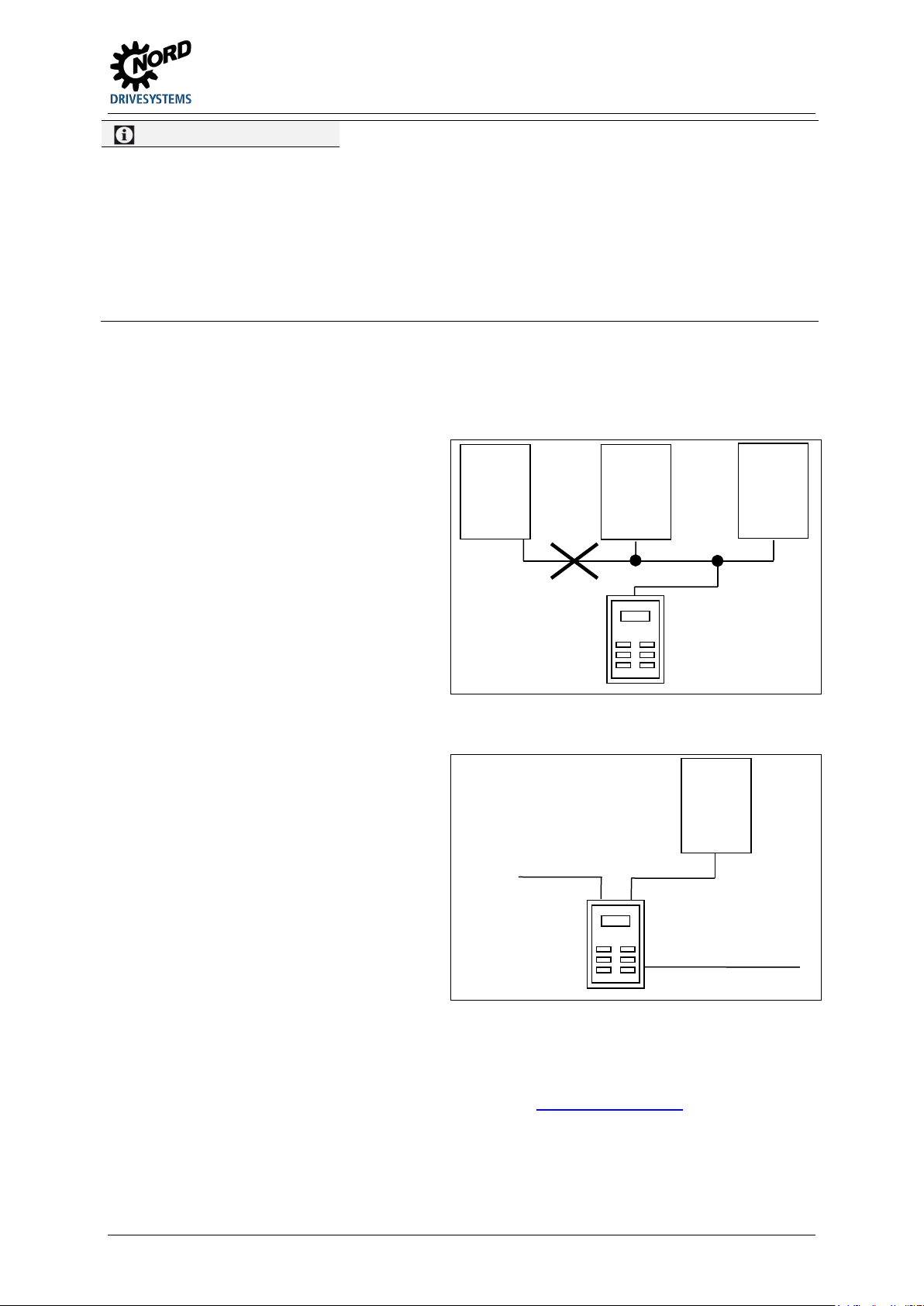
4 Commissioning
Information
Addressing device selection
Using an addressing device which is
bus, you can
network via an appropriate access. The
AS
addressing device
AS-i
AS-i
addressing device
AS-i
cable
External voltage supply
Jumper position "AS-I" (factory setting)
• The use of an addressing device with a separate 24 V connection is recommended.
• The use of a battery-operated addressing device is only possible if the total power consumption of the motor
starter (up to 240 mA, depending on connected initiators or the like) does not exceed the current rating of the
addressing device.
Jumper position "AUX"
• The use of a battery-operated addressing device or an addressing device with a separate 24 V DC
connection is possible.
Ways in which AS-i Slave addressing can be implemented in practice with an addressing device,
provided that the yellow AS interface cable is used for transferring data and supplying the motor
starter (jumper position AS-I), are shown in the following.
Version 1
equipped with an M12 connector for
connecting to the AS-i
incorporate yourself into a the AS interface
AS-i
Master
AS-i
Power
Power
prerequisite for this is that the AS interface
master can be switched off.
Version 2
With an addressing device that is equipped
with an M12 connector for connecting to the
AS-i bus and an additional M12 connector
for connecting an external voltage supply,
the addressing device can be directly
incorporated in the AS-i cable.
-i
AS-i
slave
4.3.5 Certificate
Currently available certificates can be found on the Internet at Link "www.nord.com"
BU 0135 en-4118 75
Page 76

NORDAC START (SK 135E / SK 175E) – Users Manual for Motor Starters
4.4 PROFIBUS DP
This section is only relevant for device of type SK 175E-...-PBR.
4.4.1 The bus system
PLC's, PC's, operating devices and monitoring devices can all communicate via a uniform bus in serial
bit mode using PROFIBUS DP. PROFIBUS DP is preferably used where time-critical rapid and
complex communication between individual devices is required. The bus system is suitable as a
substitute for cost-intensive parallel 24 V DC signal transfer of process data.
PROFIBUS communication is specified in the international standards IEC 61158 and IEC 61784.
Application and planning aspects are specified and documented in the guidelines of the PROFIBUS
users´ organisation (PNO). This ensures that devices from different manufacturers can communicate
with each other. The data exchange is specified in DIN 19245 parts 1 and 2 and application-specific
extensions in part 3 of this standard. As part of the European field bus standardisation process,
PROFIBUS is being integrated into the European field bus standard EN 50170.
4.4.2 Features
• Electrically isolated bus interface
• Status display (1 LED)
• Address setting via two rotary coding switches (beneath the casing cover)
• The PROFIBUS termination resistor can be switched in via jumpers
• Transfer of 4 control bits and 4 status bits
• Supports Sync Mode and Freeze Mode of the PROFIBUS DP communication function
• Watchdog function, in case of malfunction all bits of the setpoint PDO are set to 0
• No parameter communication
• Baud rate 12 Mbit/s
• Connection to device
– via terminal strip
– or via M12 system connectors
76 BU 0135 en-4118
Page 77
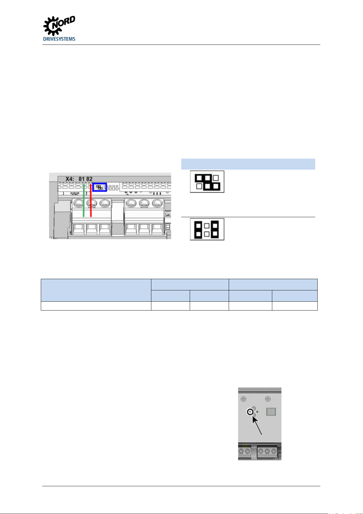
4 Commissioning
Bus terminated, terminating
SK 175E-…-PBR
81
82
44
40
4.4.3 Commissioning
4.4.3.1 Connection
Connection of the PROFIBUS cable (lilac) is made via the terminal strip and can optionally be made to
an appropriately labelled M12 flange plug contact (lilac)
The connection to the terminal strip must not be made via a stub, i.e. the "incoming" and "outgoing"
PROFIBUS cables must be connected in one terminal together using a double wire end sleeve, for
example!
Details of control terminals ( Section 2.3.3 "Electrical connection of the control unit")
Details of connectors ( Section 3.2.3.2 "Plug connectors for control connection")
Jumper position Meaning
Bus not terminated, terminating
resistor
not set (OFF)
OFF
Factory setting
resistor
set (ON)
ON
Figure 12: PROFIBUS, connecting terminals and jumper position (example of "OFF" position)
PROFIBUS DP connection Control voltage connection
Type
PBR-A PBR-B 24 V DC GND
Table 12: PROFIBUS DP, connection of signal and supply cables
In order to ensure that proper potential equalisation takes place, the connection of a second
earthing line is recommended. This must be connected to the PE connection of the device.
The bus terminating resistor is terminated at the first and last bus subscribers (see above for jumper
position SK 175E-…-PBR).
4.4.3.2 Displays
The status of the PROFIBUS is signalled by a BR LED.
BU 0135 en-4118 77
Page 78
NORDAC START (SK 135E / SK 175E) – Users Manual for Motor Starters
green ON
• Normal operation (cyclic process data communication in operation)
Bit 1
Enable left
0 1
Field of rotation right present at motor
Bit 2
Acknowledge fault 1)
1 0 Field of rotation left present at motor
1)
Acknowledge with flank 0 1.
0 = Brake applied, will be released automatically if
LED BR Meaning
OFF No cyclic process data communication active, i.e. no data communication with slave.
• PLC / Master in STOP or switched off
• Missing 24 V DC voltage supply to motor starter
• Profibus cable between PLC / Master and motor starter / Slave not connected
• Connections not connected or exchanged
• Bus terminating resistor not set correctly (at first and last slave of bus line)
• Erroneous addressing (wrong address set)
• Missing hardware configuration in PLC / Master, possible wrong GSD file
(NORD0DA5.gsd) used (Link)
4.4.3.3 Configuration
Process data
The process data is used to control the motor starter and communicate its status. The transfer of this
data is carried out cyclically. There is only one process data object (PDO) for the motor starter, with a
fixed data length of 1 byte. Only the bottom 4 bits are used. A distinction is made between the setpoint
PDO (from PLC to device (BUS-IN bits)) and the actual value PDO (from device to PLC (BUS-OUT
bit)).
Bus I/O bits
WARNING
Unexpected movement due to automatic starting
In the event of a fault (communication interrupted or bus cable disconnection, the device automatically switches
off, since the device enable is no longer present.
Restoration of communication may result in an automatic start and therefore, unexpected movement of the drive
unit. To prevent any hazard, a possible automatic start must be prevented as follows:
• If a communication error occurs, the bus master must actively set the control bits to "zero".
The device is equipped with two additional digital inputs for connecting initiators. However, there are
no optional outputs for connecting actuators which are operated directly via the BUS. The following
connections are each provided for four reference data bits:
BUS-IN Function (P420[-04…-07])
Bit 0 Enable right 0 0 Motor is switched off
Bit 3 Release brake manually 2) 1 1 Motor is switched off
Status
Status
Bit 1 Bit 0
For control via the bus, acknowledgem ent is not
automatically performed by a flank on one of the
enable inputs
2)
required
1 = Brake is released immediately.
78 BU 0135 en-4118
Page 79
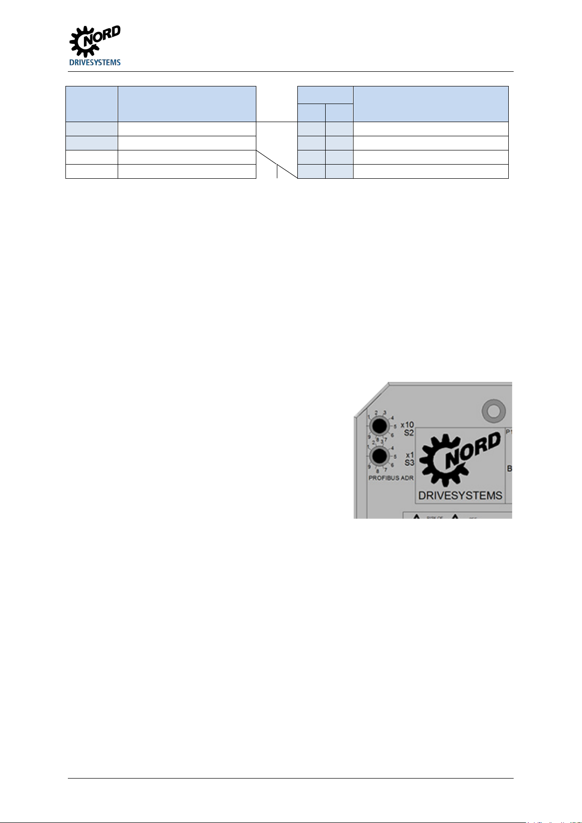
4 Commissioning
Bit 0
Fault (status bit 0)
0 0
Error active
Bit 2 1)
Status of initiator 1 (DIN3 / C1)
1 0 Warning (but motor running)
Bit 3 1)
Status of initiator 2 (DIN4 / C2)
1 1 Run (motor running without warning)
The motor switch is addressed via two decimal rotary
Setting of 10's location of the address. The setting
BUS-OUT Function (P434 [-01 … -02])
Bit 1 Operation (status bit 1) 0 1 Standby (motor stationary)
Bits 2 and 3 are directly coupled to digital inputs 3 and
1)
4.
Parallel actuation via the BUS and the digital inputs (C1, C2) is possible. The relevant inputs are dealt
with more or less as normal digital inputs. If a changeover between manual and automatic is going to
take place, it must be ensured that no enable via the normal digital inputs takes place in automatic
mode. This could be implemented e.g. with a three-position key switch. Position 1: "Manual left"
Position 2: "Automatic" Position 3: "Manual right".
If an enable is present via one of the two "normal" digital inputs, the control bits from the bus system
are ignored. An exception is the control bit "Acknowledge fault". This function is always possible in
parallel, regardless of the control hierarchy. The bus master can therefore only take over control if no
actuation via a digital input takes place. If "Enable left" and "Enable right" are set simultaneously, the
enable is removed and the motor stops without a deceleration ramp (block voltage).
Status
Status
Bit 1 Bit 0
4.4.3.4 Addressing
coding switches.
Switch "x1 S3"
• Setting of decimal number range from 0 to 9
Switch "x10 S2"
•
range 0 to 9 is linked with a factor of 10.
Example
Switch S2 = 4 ( 4x)
Switch S3 = 2 ( x2)
Resulting PROFIBUS address = 42
The PROFIBUS address of the motor starter can be set within a range of 1 to 79 and 81 to 99 with the
rotary coding switches.
If addresses 0 or 80 are set, the motor starter interprets these values as an address of 126.
Communication is not possible in this case.
The address is read in directly after switching on the 24 V supply of the motor starter.
An address change only comes into affect on the voltage supply of the device after switching the
24 V DC on again!
BU 0135 en-4118 79
Page 80
NORDAC START (SK 135E / SK 175E) – Users Manual for Motor Starters
Operating displays
(P0--)
Display of parameters and operating values
Motor data
(P2--)
Electrical settings for the motor (motor current or starting voltage (start-off
Control terminals
(P4--)
Assignment of functions for the inputs and outputs
Information
(P7--)
Display of operating values and status messages
Information
Factory setting P523
5 Parameter
WARNING
Parameter changes become effective immediately. Dangerous situations can occur under certain conditions,
even when the drive is stationary. Functions such as P428 "Automatic Start" or P420 "Digital inputs" or the
"Release Brake" setting can put the drive in motion and put persons at risk due to moving parts.
Therefore:
• Changes to parameter settings must only be made when the frequency inverter is not enabled.
• During parametrisation work precautions must be taken to prevent unwanted drive movements (e.g. lifting
gear plunging down). The danger area of the system must not be entered.
The relevant parameters for the device are described in the following. The parameters are accessed
using a parametrisation tool (e.g. NORDCON software or control and parametrisation unit, see also
( Section 3.1 "Control and parametrisation options ") and therefore makes it possible to adapt the
device to the drive task in the best possible way. Different device configurations can result in
dependencies for the relevant parameters.
The parameters can only be accessed if the control unit of the device is active.
The device must be provided with a 24 V DC control voltage to do this ( Section 2.3.3 "Electrical
connection of the control unit").
Unexpected movement due to parameter changes
Connections and possible priority switching with the potentiometers (P1…) and the DIP switch (S1)
are described in a suitable location and must be taken into consideration (pay attention to P130).
Parameter changes only have a direct influence on the RAM memory of the device and are therefore
volatile. In order to retain these changes, a copy job (P550) must be triggered after completing the
parameter changes. This causes the data to be transferred to the permanent memory (Flash memory)
of the device.
The individual parameters are functionally combined in groups. The first digit of the parameter number
indicates the assignment to a menu group:
Menu group No. Master function
Basic parameters (P1--) Basic device settings such as behaviour when switching on/off
voltage))
Additional parameters (P5--) Priority monitoring function and other parameters
The factory settings of the entire parameter set can be loaded at any time using parameter P523. For example,
this can be useful during commissioning if it is not known which device parameters have been changed earlier,
and could have an unexpected influence on the operating behaviour of the drive.
Restoring the factory settings (P523) affects all parameters. This means that all motor data must subsequently be
checked or reset.
The potentiometers (P1-P4) and DIP switches (S1) are also reactivated.
80 BU 0135 en-4118
Page 81

5 Parameter
Operating displays
P000
Operating display
P001
Selection of display value
P003
Supervisor code
P108
Switch-off mode
P114
Brake delay off
P130
Parameter source
P131
Phase control mode
Motor data
P203
Rated motor current
P210
Start voltage
P215
Boost voltage
Control terminals
P400
Function Analogue input
P420
Digital inputs
P427
Emerg. stop Fault
P428
Automatic starting
P434
Digital output
P499
Function DIP switch
Additional parameters
P580
P581
P582
Information
P700
Present Operating
P707
Software version
P708
Status of digital in.
P721
P722
P723
P724
P725
P726
P727
Mechanical power
P728
Current mains voltage
P732
Phase U current
P733
Phase V current
P734
Phase W current
P740
Process data Bus In
P741
Process data Bus Out
P743
Device type
P744
Configuration
P749
Status of DIP switches
P762
Phase U voltage
P763
Phase V voltage
P764
Phase W voltage
5.1 Parameter overview
Basic parameters
P102 Acceleration time P103 Run time P107 Brake reaction time
P216 Time boost
P523 Factory setting P535 I²t motor P538 Mains voltage
Monitoring
P539 Output monitoring P550 Flash copy order P570 Locking time
Error in the event of
overtemp.
Phase sequence
Manual brake release
detection
status
P709 Potentiometer status P711 Digital output status P716 Current frequency
P718 Mains frequency P719 Actual current P720 Effective current
Reactive current
Voltage -q
Current voltage
Current cos phi
Voltage -d
Apparent power
BU 0135 en-4118 81
Page 82
NORDAC START (SK 135E / SK 175E) – Users Manual for Motor Starters
Arrays
[-01]
Factory setting
Note
Setting values
Information
Description of parameters
S
Supervisor-Parameter
The parameter can now be displayed and modified if the
P
Parameter set-dependent
The parameter provides different setting options that are
RM
RAM
The parameter can be modified but not stored in the Flash
RF
P130
5.2 Description of parameters
P000 (parameter number) Operating display (parameter name) xx 1) S P
Setting range
(or display range)
Scope of Application
Description
Display of typical display format (e.g. (bin =
binary)) of possible setting range and number
of decimal places
If parameters have a substructure in several arrays, this is shown here.
{ 0 }
List of device variants to which this parameter applies. If the parameter is generally valid, i.e. for the entire
model series, this line is omitted.
Description, functionality, meaning and the like for this parameter.
Additional notes about this parameter
List of possible settings with description of the respective functions
Default setting that the parameters t ypically have in the as-delivered condition of the device or to
which it is set after carrying out "Restore factory settings" (see parameter P523).
(and display values)
1) xx = other identification
Figure 13: Explanation of parameter description
Other applicable
parameter(s):
List of other parameters that
are directly associated
Unused lines of information are not listed.
Note / Explanation:
Code Designation Meaning
relevant supervisor code has been set (see parameter
P003).
dependent upon the selected parameter set.
RD READ Parameter can only be read.
memory.
READ/FLASH According to the setting of parameter
can either only be read or can be changed and saved in the
flash memory.
FL FLASH The parameter is read out of the flash memory and can be
changed.
, the parameter
82 BU 0135 en-4118
Page 83
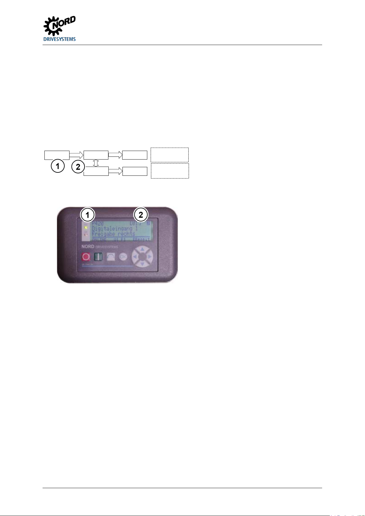
5 Parameter
P 01
P420
P 02
1
0
Meaning:
Digital input 1,
enable right function
Meaning:
Digital input 2,
no function
ENTER
ENTER
ENTER
VALUE
1
2
Array
1
Parameter number
2
Array
Array parameter display
Some parameters have the option of displaying settings and views in several levels ("arrays"). After
the parameter is selected, the array level is displayed and must then also be selected.
If the SimpleBox SK CSX-3H is used, the array level is shown by _ - 0 1. With the ParameterBox
SK PAR-3H (picture on right) the selection options for the array level appear at the top right of the
display (Example: [01]).
Array display:
SimpleBox SK CSX-3H
Parameter number
ParameterBox SK PAR-3H
BU 0135 en-4118 83
Page 84
NORDAC START (SK 135E / SK 175E) – Users Manual for Motor Starters
Display range
Description
In the SimpleBox (SK CSX-3H) display, the operating value selected in parameter
Setting range
0 … 11
Factory setting
Description
Selection of the operating value to be displayed (see P000)
Setting values
1 Nominal frequency
[Hz]
Effective current currently being supplied by device
Reactive current currently being supplied by device
5 Mains voltage
[V]
6 cos Phi
[-]
Calculated value of current apparent power
Calculated value of current effective power
9
Mains phase sequence
[-]
0 = Clockwise rotating field
1 = Counter-Clockwise rotating field
0 % = "Motor off", 100 % = "Motor voltage = Mains voltage"
Actual current
amplification
Factory setting
{ 1 }
Setting values
0 Supervisor mode off
The supervisor parameters are not visible.
5.2.1 Operating displays
P000 Operating display RD
0.01 … 9999
Other applicable parameter(s): P001
online is displayed.
P001 Selection of display value RM
Other applicable parameter(s): P000
{ 0 }
0 Actual frequency [Hz]
2 Current [A]
4 Reactive current [A]
8 Effective power [kW ]
Value Meaning
Output frequency currently being supplied by device
Frequency of mains voltage that is currently present
Current output current measured by device
3 Effective current [A]
Voltage currently being measured at the input terminals
Calculated value of current power factor
7 Apparent power KVA
10 Duty factor [%]
11
Phase angle control value currently being achieved by device.
[%]
Actual measured current in relation to the measurement range
P003 Supervisor code RM
Setting range 0 … 9999
Description The scope of the visible parameters can be influenced by setting the supervisor code.
1 Supervisor mode on
2 … Supervisor mode off
Value Meaning
The supervisor parameters are not visible.
All parameters are visible.
84 BU 0135 en-4118
Page 85

5 Parameter
Setting range
0.00 ... 25.50 s
Description
The acceleration time is the time that the drive needs to reach the maximum speed
Note
As long as parameter P130=0 is set, the acceleration time is determined via
If the motor is idling or in the case of drives with extremely low counter-torque, the soft
Setting range
0.00 ... 25.50 s
Description
The run-down time is the time that the drive needs to reach a speed of "0" after the
Note
As long as parameter P130=0 is set, the run-down time is determined via
If the motor is idling or in the case of drives with extremely low counter-torque, the soft
Setting range
0.00 ... 25.50 s
Description
Time delay for the application (closing) of an electro-magnetic brake after the run-
Note
In switch off mode 4 (DIP switch S1-DIP3/4) the application time of the brake is
Depending on the reaction time of the brake, the motor can be expected to switch off
5.2.2 Basic parameters
P102 Acceleration time RF
Other applicable parameter(s): P130, P216
Factory setting { 1.00 }
after receiving the enable. Since the acceleration time is determined by the phase
control variation, it is only a case of indirect control of the acceleration time here. The
actual acceleration time of the motor essentially depends on the motor which is used,
the inertial masses and the counter-torque.
potentiometer P4. In this case the parameter can only be read, but not changed. It
then corresponds to the setting determined by the potentiometer.
start should be selected. Because the inertial masses and the counter-torque are
disproportional, the phase control procedure cannot control the drive properly. The
drive unit and its surroundings may be subjected to unwanted mechanical loads
P103 Run-down time RF
Factory setting { 1.00 }
(vibration or the like).
Other applicable parameter(s): P107, P108, P130
enable has been removed. Since the run-down time is determined by the phase
control variation, it is only a case of indirect control of the run-down time here. The
actual run-down time of the motor essentially depends on the motor which is used, the
inertial masses and the counter-torque.
potentiometer P4. In this case the parameter can only be read, but not changed. It
then corresponds to the setting determined by the potentiometer.
start should be selected. Because the inertial masses and the counter-torque are
disproportional, the phase control procedure cannot control the drive properly. The
drive unit and its surroundings may be subjected to unwanted mechanical loads
(vibration or the like).
P107 Brake reaction time FL
Other applicable parameter(s) P103, P108
Factory setting { 0.00 }
down time has been reached (P103) or the enable removed.
Once the motor starter has blocked its voltage at the output, a connected mechanical
brake remains open until the time set in P107 has elapsed. This allows the motor to
reduce its speed or even stop before the brake is applied.
determined by parameter P103/Potentiometer P4.
before the brake is applied. For lifting equipment applications, this means that there is
BU 0135 en-4118 85
a risk of the load dropping at the time of stopping.
Page 86
NORDAC START (SK 135E / SK 175E) – Users Manual for Motor Starters
Factory setting
{ 2 }
Description
This parameter determines the reaction of the motor starter on the removal of the
Setting values
0
Switch-off mode 1
The phase control becomes continuous, increased from 0 to 100%
time specified by P107 or P4.
P107 or P4.
when the voltage reaches "0 %" or after P107 has elapsed.
The output voltage is shut off immediately and the brake is applied
in accordance with the time specified by P103 or P4.
Factory setting
{ 0.05 }
Note
Electromagnetic brakes have a delayed reaction time for their release, which depends
Setting range
0 … 1
Factory setting
{ 0 }
Note
• Switch-over of P130 from setting 1 0:
Setting values
0
Potentiometer/Switch
All parameters which are marked "RF" can only be read but cannot
be changed. These are determined by (S1) and (P1-P4).
outputs are determined via the parameters (P420 or P434).
P108 Switch-off mode RF
Setting range 0 … 3
enable.
Note As long as parameter P130=0 is set, switch-off mode is determined via the DIP switch
S1-DIP3/4. In this case the parameter can only be read, but not changed. It then
corresponds to the setting that is determined by the DIP switch. ( Section 4.2.2.4
"Overview of switch-off modes")
Value Meaning
within the time period in accordance with P103 or potentiometer P4
(voltage drops). The brake is then applied in accordance with the
Other applicable parameter(s): P103, P107, P130, P210
1 Switch-off mode 2
2 Switch-off mode 3
3 Switch-off mode 4
The phase control becomes continuous, increased from a start
value (Y) to 100% within a time period (X) (voltage drops). The
start value (Y) is determined by P210 or potentiometer P3. The
time period (X) is determined by P103 or potentiometer P4,
whereby the starting point of the time axis is shifted to the
theoretical start value (Y=0 %).
The brake is then applied in accordance with the time specified by
The output voltage is shut off immediately and the brake is applied
P114 Brake release time FL
Setting range 0.00 ... 25.50 s
Description Setting of the time delay for enabling the motor after switch on.
on physical factors. If the brake release time set in parameter P114 is too long the
motor operates against the brake, which is still applied. This can result in a start-up
current that is too high, which will make the starter shut off with an overcurrent error.
P130 Parameter source FL
Other applicable parameter(s) P550
Description Selection of whether the DIP switches (S1) and potentiometers (P1-P4) have priority
over the parameter setting.
The RAM memory is deleted, parameter settings which have not been transferred
to the flash memory (P550) are lost.
• Switch-over of P130 from setting 0
1:
The default values of the parameter are used. To adopt parameter values from the
flash memory the FI must be restarted (note the wait time between two mains
switch on cycles! ( Section) 7 "Technical data").
86 BU 0135 en-4118
Value Meaning
1 Flash memory
2 Potentiometer switch + flash
All settings at the device are determined by the parameters. (S1)
and (P1-P4) have no influence.
As for setting "0" However, the functions of the digital inputs and
Page 87
5 Parameter
Setting range
0 … 1
Description
Adaptation of the operating behaviour (running characteristics) of the motor
idling motor.
Optimisation of phase control for reduced tendency to oscillate with
idling motors or long ramps.
Setting range
1.00 … 28.00 A
Factory setting
{ 3.00 }
Note
As long as parameter P130=0 is set, the rated motor current is determined via
Setting range
10.0 … 100.0 %
Description
The start voltage is the voltage that the device supplies immediately after setting the
Note
As long as parameter P130=0 is set, the rated motor current is determined via
Setting range
0.0 … 100.0 %
Factory setting
{ 0.0 }
Setting range
0.00 ... 25.50 s
Description
P216 defines the time limit of the boost voltage (P215) or the increased starting
Note
The resulting acceleration time (T
), which achieved until full control of the voltage,
P131 Phase control mode FL
Factory setting { 0 }
Setting values
Value Meaning
0 Current-optimised
1 Oscillation-optimised
Optimisation of phase control for an even current flow. This
reduces the losses in the motor when starting up, but leads to an
increased tendency to oscillate in the event of long ramps and an
5.2.3 Motor data
P203 Rated motor current RF
Other applicable parameter(s): P130
Description The rated motor current is needed for I2t monitoring. For normal applications, the
setting corresponds to the nominal current as per the motor type plate.
potentiometer P1. In this case the parameter can only be read, but not changed. It
P210 Start voltage RF
Factory setting { 50.0 }
then corresponds to the setting determined by the potentiometer.
Other applicable parameter(s): P108, P130
enable at the motor terminals.
potentiometer P3. In this case the parameter can only be read, but not changed. It
then corresponds to the setting determined by the potentiometer.
Setting values 100.0 = the soft start is disabled.
P215 Boost voltage FL
Other applicable parameter(s): P210, P216
Description The boost voltage determines a boost to the start voltage in the starting phase. The
required breakaway torque is therefore provided for drives with increased starting
torque.
Note The boost voltage time is limited by P216.
P216 Time boost FL
Other applicable parameter(s): P102, P215
Factory setting { 0.00 }
torque.
total
is calculated accordingly as: T
total
= T
P102
+ T
P216
.
BU 0135 en-4118 87
Page 88
NORDAC START (SK 135E / SK 175E) – Users Manual for Motor Starters
Display range
0 … 6
Arrays
[-01] =
Function Analogue input 1
[-02] =
Function Analogue input 2
[-03] =
Function Analogue input 3
[-04] =
Function Analogue input 4
Description
Representation of function of respective potentiometer P1 … P4, for as long as the
Display values
0 No function
The potentiometer supplies the value for P570
P210
4 Ramp times
P102 / P103
5.2.4 Control terminals
P400 Function Analogue input RD
Other applicable parameter(s): P102, P103, P130, P203, P210, P570
(= value for P203 from potentiometer P1)
(= value for P570 from potentiometer P2)
(= value for P210 from potentiometer P3)
(= value for P102 / 103 from potentiometer P4)
relevant potentiometer is active.
Note If P130=1 is set, all potentiometers are inactive. "0" = "No function" is displayed in all
arrays.
1 Rated motor current
2 Locking time
5 … reserved
Value Meaning
The potentiometer is not used.
The potentiometer supplies the value for P203
3 Starting torque
The potentiometer supplies the value for
The potentiometer supplies the value for
88 BU 0135 en-4118
Page 89
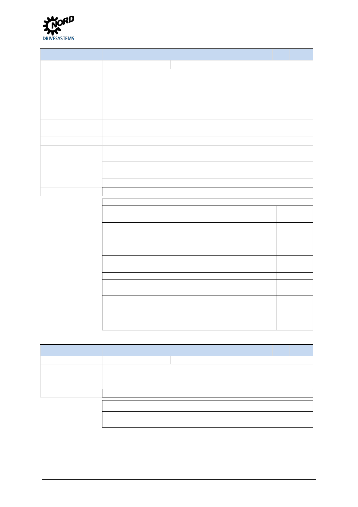
5 Parameter
Setting range
0 … 9
[-07] =
Bus In bit 3
{ [-05] = 4 }
{ [-06] = 7 }
{ [-07] = 9 }
Note
In order to change parameter values, P130=1 must be set. Otherwise the settings of
Non-permissible settings are ineffective and are not saved.
Arrays [-04 … -07] are only active for SK 175E devices.
Setting values
The input is not used.
1
Enable right
The drive runs with a right-hand direction of
(only for array [-01 and -02])
(only for array [-04 ... -07])
4
Enable left via bus
The drive runs with a left-hand direction of
(only for array [-04 ... -07])
mode).
7
Fault acknowledgement
Acknowledge fault message.
the message is not longer present.
or automatically (signal "low")
1)
If DIP switch 1 (S1) or parameter P428 are parametrised to "Automatic Start-up" depending on
parameter P130, no flank is required. A "High Level" is sufficient.
Setting range
0 … 1
Description
Emergency stop fault - decision as to how the motor starter should react in the event
Setting values
An error leads to immediate motor starter shut-off (motor runs
down to a standstill and brake, if present, is applied immediately)
P420 Digital inputs RF
Other applicable parameter(s): P130, P428
Arrays [-01] = Digital input 1 (= value for digital input DIN1)
[-02] = Digital input 2 (= value for digital input DIN2)
[-03] = PTC input (= value for PTC input TF)
[-04] = Bus In bit 0 (= value for Bus In bit 0)
[-…] …
(= value for Bus In bit 3)
Factory setting { [-01] = 1 } { [-02] = 2 } { [-03] = 8 } { [-04] = 3 }
Description Assignment of functions for the various digital inputs.
P420 can only be read.
The parametrisation of array [-03] cannot be changed.
0 No function
5 Disable voltage (coast to stop)
8 PTC resistor input
Value Meaning
rotation.
2 Enable left
3 Enable right via bus
6 Emergency stop
9 Release the brake
The drive runs with a left-hand direction of
rotation.
(only for array [-01 and -02])
The drive runs with a right-hand direction of
rotation.
rotation.
Drive runs down to a standstill. Low active
Drive switches to "Switch=on block" after
switching off (termination of selected switch-off
Acknowledgement only possible if the cause of
For evaluating a PTC signal. High active
The brake is released manually (signal "high")
High active
Flank 0 1
High active
Flank 0 1
High active
Flank 0 1
High active
Flank 0 1
Low active
Flank 0 1
High active
1)
1)
1)
1)
P427 Emerg. stop Fault FL
Other applicable parameter(s): P108, P130, P428
Factory setting { 0 }
of an error.
Value Meaning
0 Off
1 On
With errors E2.0, E3.0, E5.1, E6.1 the drive is run down in the
selected switch-off mode before the motor starter shuts off with an
error message.
BU 0135 en-4118 89
Page 90
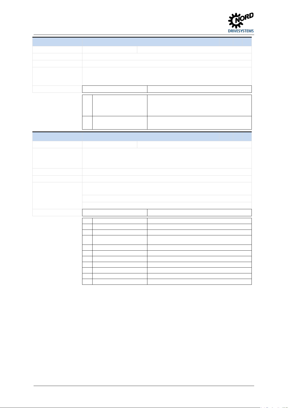
NORDAC START (SK 135E / SK 175E) – Users Manual for Motor Starters
Factory setting
{ 0 }
Description
Decision as to whether the motor starter should react to an enable signal.
Note
As long as parameter P130=0 is set, the automatic start-up is determined via DIP
Setting values
0
Off
The device expects a flank (signal change "low high") at the
voltage on), it immediately switches to "Switch-on block).
NOTICE! Danger of injury! Drive starts up immediately!
Setting range
0 … 9
Factory setting
{ [-01] = 1 }
{ [-02] = 2 }
{ [-03] = 3 }
Description
Assignment of functions for the various digital outputs.
Non-permissible settings are ineffective and are not saved.
The parametrisation of array [-03] cannot be changed.
Error or warning is active.
3
Mechanical brake
A mechanical brake is actuated (terminals 79/80).
"High Signal" = brake releases
Display of signal status of digital input 2
6 Status bus Dig In 1
7 Status bus Dig In 2
Display of signal status from digital input 4 via Bus 1)
10
Remote control active
1)
Only SK 175E via integrated AS interface or PROFIBUS DP
P428 Automatic starting RF
Setting range 0 … 1
switch S1-DIP1. In this case the parameter can only be read, but not changed. It then
corresponds to the setting that is determined by the DIP switch.
Value Meaning
digital input which has been parametrised to "Enable" in order to
start the drive.
If the device is switched on with an active enable signal (mains
Other applicable parameter(s): P130, P428
1 On
The device expects a signal level ("high") at the digital input which
has been parametrised to "Enable" in order to start the drive.
P434 Digital output function RF
Other applicable parameter(s): P130
Arrays [-01] = Dig.1/Bus.bit 0 outp (= value for digital output DO1 or Bus Out bit 0)
[-02] = Dig.2/Bus.bit 1 outp (= value for digital output DO2 or Bus Out bit 1)
[-03] = Mechanical brake (= value for mechanical brake MB)
Note In order to modify the parameter values, P130=1 must be set. Otherwise the settings
of P434 can only be read.
Setting values
0 No function
1 Error / Warning
2 Motor running
4 Digital-In 1 status
5 Digital-In 2 status
8 Status bus Dig In 3
9 Status bus Dig In 4
Value Meaning
The output is not used.
Drive operates.
Display of signal status of digital input 1
Display of signal status of digital input 1 via bus 1)
Display of signal status from digital input 2 via Bus 1)
Display of signal status from digital input 3 via Bus
The device is controlled via the Bus
1)
90 BU 0135 en-4118
Page 91
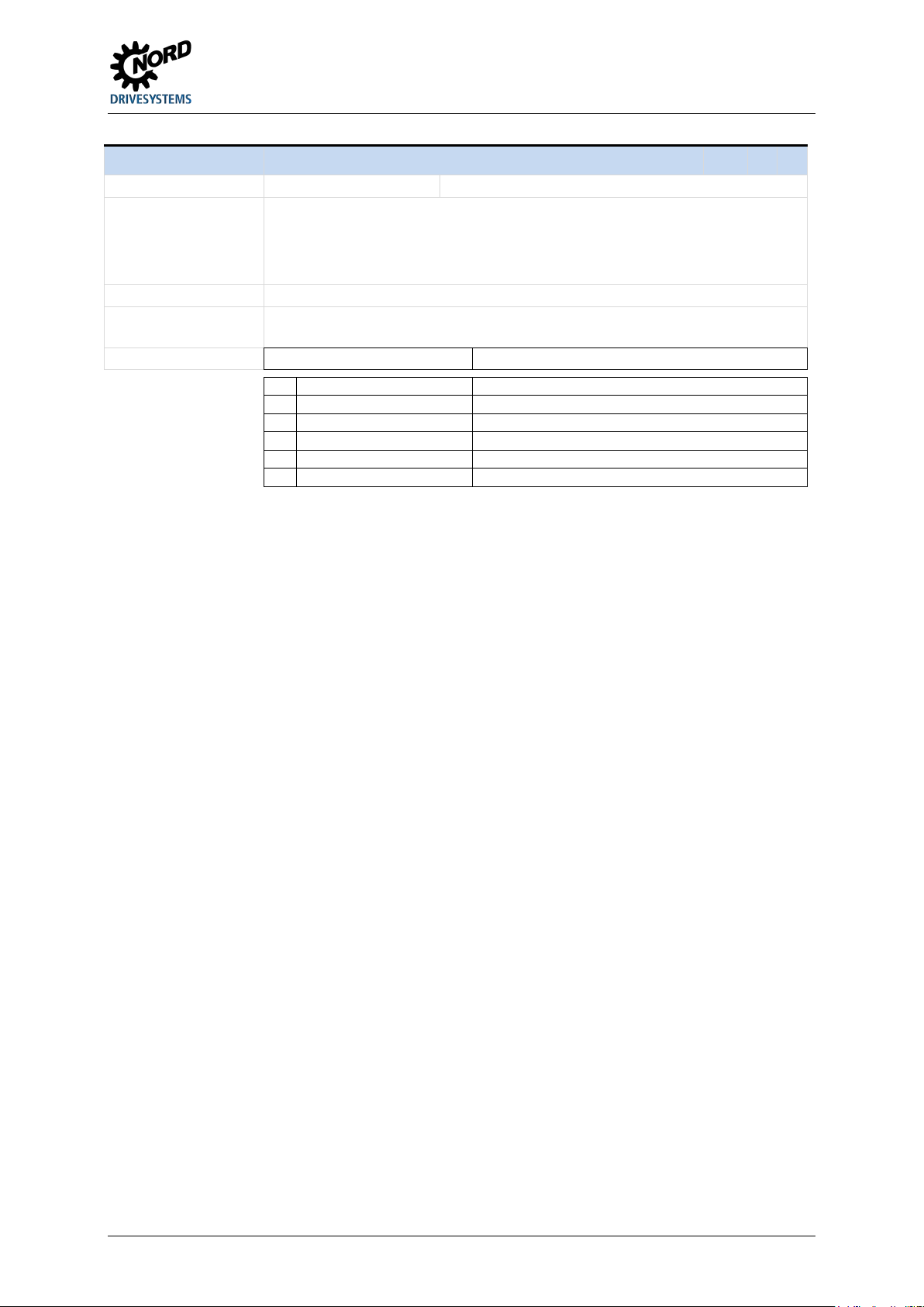
5 Parameter
Display range
0 … 6
Arrays
[-02] =
Function DIP switch 2
[-03] =
Function DIP switch 3
[-04] =
Function DIP switch 4
Description
(S1)
Note
If P130=1 is set, all DIP switches are inactive. "0" = "No function" is displayed in all
Display values
0 No function
1 Automatic starting
reserved
P108
6 Switch-off mode bit 1
P108
P499 Function DIP switch RD
Other applicable parameter(s): P108, P130, P428, P570
[-01] = Function DIP switch 1 (= value for P428)
(= value for P581)
(= value for P108 (bit 0))
(= value for P108 (bit 1))
Display of functions of DIP switch
arrays.
2 Phase sequence detection
3 - 4
Value Meaning
5 Switch-off mode bit 0
.
The DIP switch is not used
The DIP switch supplies the value for P428
The DIP switch supplies the value for P581
The DIP switch supplies the value for
The DIP switch supplies the value for
– bit 0
– bit 1
BU 0135 en-4118 91
Page 92
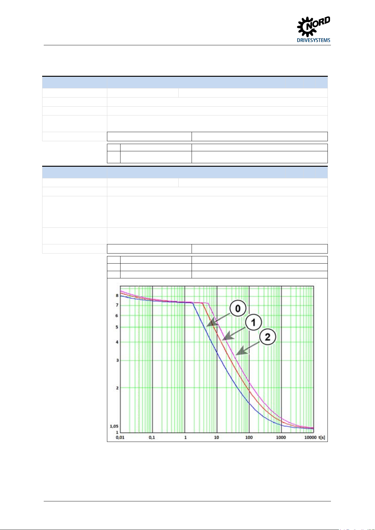
NORDAC START (SK 135E / SK 175E) – Users Manual for Motor Starters
Setting range
Factory setting
{ 0 }
Description
Reset all motor start parameters to the factory settings.
Setting values
0 No change
jumps back to a value of "0".
Setting range
0 … 2
Description
I²t motor shut-off class – This determines how quickly the motor starter shuts off in the
Note
The three selectable motor shut-off classes are based on curves that are defined in
Setting values
1.5 times overcurrent for 120 s
1 Class 10
5.2.5 Additional parameters
P523 Factory setting RM
0 … 1
Note The setting is not permanent until the values from the RAM have been transferred to
the Flash memory (see P550).
Value Meaning
This function is not implemented.
1 Load factory setting
All parameters are reset to the factory settings. The display then
P535 I²t motor FL
Other applicable parameter(s): P108, P203, P427
Factory setting { 1 }
event of overcurrent. The rated current upon which the I²t monitoring is based is
determined by P203. The shut-off takes place almost immediately as of 7.2 times the
rated current.
(Error E3.0)
Other applicable parameter(s): P550
EN 60947-4-2.
0 Class 10A
2 Class 20
Value Meaning
1.5 times overcurrent for 240 s
1.5 times overcurrent for 360 s
92 BU 0135 en-4118
Page 93
5 Parameter
Setting range
0 … 3
Factory setting
Description
Mains voltage monitoring – Selection of variant of mains monitoring (terminals
Note
For reliable operation of the device, the power supply must meet a certain quality. If
If the monitoring is disabled, mains errors can lead to undefined operating behaviour.
Phase errors lead to error message (E7.0)
Overvoltage and undervoltage in the supply network lead to an
error message (E5.1, E6.1)
E5.1, E6.1, E7.0
Setting range
0 … 3
Description
Selection of output monitoring variant (terminals U-V-W) by the device.
Setting values
No monitoring of the output voltage
Phase errors (asymmetries of measured output current) lead to
error message (E016).
E016
errors lead to error message (E016).
Setting range
0 … 1
Factory setting
{ 0 }
Note
Parameter changes initially only affect the volatile RAM memory, and are lost when
A maximum of 100 copy processes can be guaranteed.
"RESET". Parameter P550 is reset to "0".
P538 Mains voltage Monitoring FL
Other applicable parameter(s): P108, P427
{ 3 }
L1-L2-L3) by the device.
there is a brief interruption of a phase or the voltage supply exceeds a particular limit
value, the device outputs an error.
Setting values
0 Switched off
Value Meaning
No monitoring of the supply voltage.
1 Phase error
2 Mains voltage
3 Phase err. + mains voltage
Combination of settings 1 and 2. Phase errors or mains errors
lead to an error message (
)
P539 Output monitoring FL
Other applicable parameter(s): P203
Factory setting { 3 }
0 Switched off
Value Meaning
1 Motor phases only
2 Magnetisation only
If the measured output current is less than 20 % of the rated motor
current (P203 or potentiometer P1) during normal operation (after
completion of the acceleration time), this leads to error message
(
).
3 Motor phase + Magnet.
Combination of settings 1 and 2. Phase and magnetisation
P550 Flash copy order RM
Description Transfer the modified parameter settings to the (non-volatile) Flash memory of the
device.
the device is switched off. In order to retain the parameter changes permanently, they
must be transferred to the Flash memory.
Setting values
0 No change
BU 0135 en-4118 93
Value Meaning
This function is not implemented.
1 RA M -> Flash
Copying process starts. The device then carries out an automatic
Page 94
NORDAC START (SK 135E / SK 175E) – Users Manual for Motor Starters
Factory setting
{ 0.50 }
Description
The locking time determines the period of time during which the motor is not powered
Setting range
0 … 1
Factory setting
{ 1 }
Setting values
0 Off
overtemperature
Setting range
0 … 1
Factory setting
Description
Analysis of phase sequence of supply network by the device and automatic adaptation
Note
As long as parameter P130=0 is set, phase sequence detection is determined via the
Setting values
of rotation of the supply network.
1
On
The direction of rotation of the motor is determined by the enable
direction.
Setting range
Factory setting
{ 0 }
Description
Definition of conditions for releasing a connected electro-mechanical brake
Setting values
0 Off
P570 Locking time RF
Setting range 0 … 25.50 s
after the end of the run-down time and before the acceleration time started in the
event of a change of rotating direction (reversing).
Note As long as parameter P130=0 is set, the locking time is determined via potentiometer
P2. In this case the parameter can only be read, but not changed. It then corresponds
to the setting determined by the potentiometer.
If the locking time is insufficient, the motor may still be rotating at the end of the rundown time. Starting in the opposite direction of rotation would result in the motor being
subjected to excessive loads (thermal, mechanical) because of the counter-current
braking that occurs as a result.
P580 Error in the event of overtemp. RF
Description Fault shut-off due to overtemperature – selection of whether an over temperature error
(PTC) should lead to a warning or a fault shut-off.
Value Meaning
Warning (C002) due to overtemperature
1 On
Fault message (E002) and shut-off of device due to
P581 Phase sequence detection RF
{ 0 }
Other applicable parameter(s): P102, P103, P108, P130
Other applicable parameter(s): P108, P427
Other applicable parameter(s): P130, P428
of rotary field of motor to the required direction of rotation.
DIP switch S1-DIP2. In this case the parameter can only be read, but not changed. It
then corresponds to the setting that is determined by the DIP switch.
Value Meaning
0 Off
The direction of rotation of the motor is determined by the direction
P582 Manual brake release RF
0 … 1
Other applicable parameter(s): P420
Note DANGER! With certain drive tasks (e.g. lifting gear) it can be dangerous to release of
the brake without the drive running (risk of raised load falling)!
Value Meaning
The brake is only released if the motor is enabled.
1 On
The brake is released even if the motor has not been enabled (e.g.
if a drive is to be moved for revision work). Pay attention to note!
94 BU 0135 en-4118
Page 95
5 Parameter
Display range
0.0 … 25.4
Display values
Display range
0.0 … 9999.0
Arrays
[-01] =
Software version
[-02] =
Software revision
[-03] =
Special version
Special version of the hardware/software (e.g: 0.0). The value "0"
Description
Display of software version (firmware version) of device
Display range
0000 0000 … 0111 1111
0000 … 007F
Display values
0 Digital input 1
PTC resistor input switching status
Bus In signal status In bit 0 (SK 175E-… only)
4 Bus In Bit 1
5 Bus In Bit 2
Display range
0.0 … 100.0 %
[-04] =
Potentiometer P4
Display range
0000 … 0111
00 … 07
Description
Display values
Switching status of digital output 2 or Bus Out Bit 2 1)
1)
Bus Out Bit only for devices SK 175E-….
The display for DOUT and Bus Out are "or"-ed when doing this.
5.2.6 Information
P700 Current operating status RD
Arrays [-01] = Current error
[-02] = Current warning
[-03] = Reason for switch-on
block
Current active error message (not acknowledged)
Current existing warning
Current existing reason for an active switch-on block
Description Display of current messages about operating status
Section 6 "Operating status messages"
P707 Software version RD
Version number (e.g.: V1.0)
Revision number (e.g.: R1)
stands for "Standard Version".
P708 Status of digital in. RD
(bin)
(hex)
Description Display of switching status of the digital inputs
1 Switch input 2
3 Bus In Bit 0
6 Bus In Bit 3
Value (Bit) Meaning
Switching status of digital input 1
Switching status of digital input 2
2 PTC resistor input
Bus In signal status In bit 1 (SK 175E-… only)
Bus In signal status In bit 2 (SK 175E-… only)
Bus In signal status In bit 3 (SK 175E-… only)
P709 Potentiometer status RD
Arrays [-01] = Potentiometer P1
[-02] = Potentiometer P2
[-03] = Potentiometer P3
Description Display of set values of potentiometer P1 … P4, in relation to the respective scale end
values (in %)
P711 Digital output status RD
Display of switching status of the digital inputs
0 Dig.1/Bus. bit 0
1 Dig.2/Bus. bit 1
Value (Bit) Meaning
2 Mechanical b.
BU 0135 en-4118 95
(bin)
Current value in % of 9.5 A (BG1) or 23,5 A (BG2)
Current value in % of 25.6 s
Current value in % of 100% start voltage
Current value in % of 25.6 s
(hex)
Switching status of digital output 1 or Bus Out Bit 1
Switching status of mechanical brake output
1)
Page 96
NORDAC START (SK 135E / SK 175E) – Users Manual for Motor Starters
Description
Display of current output frequency
Note
The value is calculated from the mains frequency and the selected direction of rotation
In the switched-off condition (drive not enabled) a value of "Zero" is output.
Description
Display of current mains frequency
Display range
0.0 … 999.9 A
Display range
-999.9 … + 999.9 A
Description
Motor current
Display range
-999.9 … + 999.9 A
Display range
0 … 500 V
Description
Display of current AC voltage present at the output terminals
Description
Display of current voltage component Ud
Note
Description
Display of current voltage component Uq
Description
Display of current calculated cos phi value
Description
Display of current calculated apparent power
Note
P203
Description
Display of current calculated effective power at motor
P716 Current frequency RD
Display range - 70 … + 70 Hz
when enabling takes place.
P718 Mains frequency RD
Display range - 70 … + 70 Hz
P719 Current current RD
Description Display of current output current
P720 Effective current RD
Display of current measured effective current
Display values
-999.9 … - 0.1
0 … + 999.9
P721 Reactive current RD
Value Meaning
Generator current
Description Display of current measured reactive current
P722 Current voltage RD
P723 Voltage -d RD S
Display range -500 … + 500 V
The value is typically "0".
P724 Voltage -q RD S
Display range -500 … + 500 V
Note The value is typically the same as that of parameter P722.
P725 Current cos phi RD
Display range 0.00 … 1.00
P726 Apparent power RD
Display range 0.00 … 99.99 kVA
The calculation is based on motor data (
P727 Mechanical power RD
Display range -99.99 … + 99.99 kW
96 BU 0135 en-4118
).
Page 97
5 Parameter
Display range
0 … 1000 V
Display range
0.0 … 999.9 A
Description
Note
Because of the measuring procedure, the value of P719 can deviate in spite of
Display range
0.0 … 999.9 A
Note
Because of the measuring procedure, the value of P719 can deviate in spite of
Display range
0.0 … 999.9 A
Description
Note
Because of the measuring procedure, the value of P719 can deviate in spite of
Display range
0000 … FFFF
-32768 … + 32767
[-06] =
Parameter data In 2
[-07] =
Parameter data In 3
[-09] =
Parameter data In 5
Description
P728 Present Mains voltage RD
Description Display of current supply voltage present at the input terminals
P732 Phase U current RD
Display of currently measured voltage of phase U
symmetrical output currents.
P733 Phase V current RD
Description Display of currently measured voltage of phase V
symmetrical output currents.
P734 Phase W current RD
Display of currently measured voltage of phase W
symmetrical output currents.
P740 Bus In process data RD S
(hex)
(dec)
Arrays [-01] = Control word
[-02] = … [-04]
not used
[-05] = Parameter data In 1
Data during parameter transfer:
Order label (AK), Parameter number (PNU), Index (IND),
[-08] = Parameter data In 4
Parameter value (PWE1 / PWE2)
Display of process and parameter data that is directed at the device and transmitted
via the bus.
BU 0135 en-4118 97
Page 98
NORDAC START (SK 135E / SK 175E) – Users Manual for Motor Starters
Display range
0000 … FFFF
-32768 … + 32767
[-03] =
Bus - Actual value 2
[-04] =
Bus - Actual value 3
[-06] =
Parameter data Out 2
[-08] =
Parameter data Out 4
[-09] =
Parameter data Out 5
Display range
0.25 … 11.00 kW
Description
Description
Displays the configuration of the device
reserved
Motor starter with soft start and reversing function
4-6
7 SK 175E (AS-i)
Like SK 135E + with integrated PROFIBUS DP Interface
Display range
0000 0000 … 1111 1111
00 … FF
0 … 255
Description
Display of switch status of DIP switch (S1).
Switching status of DIP switch element 2
3 DIP switch 4
Description
Display of current voltage of phase U
Note
P722
P741 Bus Out process data RD S
(hex)
Arrays [-01] = Bus status word
[-02] = Bus - Actual value 1
= Status word
Error number in high byte, warning number in low byte
Current current is relation to nominal current of device
Current effective current is relation to nominal current of device
(dec)
[-05] = Parameter data Out 1
[-07] = Parameter data Out 3
Description Display of process and parameter data that is transmitted by the device via the bus.
Data during parameter transfer.
P743 Device type RD
Display of nominal device output (e.g.: 3.00 = device with 3.0 kW nominal output)
P744 Configuration RD
Display range 0 … 11
Display values
3 SK 135E
8-10
11 SK 175E (Profibus)
Value Meaning
0-2
reserved
Like SK 135E + with integrated AS Interface
reserved
P749 Status of DIP switch RD
(bin)
(hex)
(dec)
Display values
0 DIP switch 1
1 DIP switch 2
2 DIP switch 3
Value (Bit) Meaning
Switching status of DIP switch element 1
Switching status of DIP switch element 3
Switching status of DIP switch element 4
P762 Phase U voltage RD
Display range 0 … 500 V
The value of
symmetrical output voltages.
can differ because of the measuring procedure, in spite of having
98 BU 0135 en-4118
Page 99
5 Parameter
Display range
0 … 500 V
Description
Note
The value of P722 can differ because of the measuring procedure, in spite of having
Display range
0 … 500 V
Description
Note
Because of the measuring procedure, the value of P72 can deviate in spite of
Display range
0 … 9 and A … Z
Arra ys
Description
Display of the serial number (12-digit) of the device.
P763 Phase V voltage RD
Display of current voltage of phase V
symmetrical output voltages.
P764 Phase W voltage RD
Display of current voltage of phase W
symmetrical output voltages.
P780 Device ID RD
(char)
[-01] = … [-12]
BU 0135 en-4118 99
Page 100
NORDAC START (SK 135E / SK 175E) – Users Manual for Motor Starters
ashing according to the number
6 Operating status messages
The device and technology units generate appropriate messages if they deviate from their normal
operating status. There is a differentiation between warning and error messages. If the device is in the
status "Start disabled", the reason for this can also be displayed.
The messages generated for the device are displayed in the corresponding array of parameter (P700).
The display of the messages for technology units is described in the respective additional instructions
and data sheets for the modules concerned.
Start disabled, “Not Ready” (P700 [-03])
If the device is in the status "Not Ready" or "Start Disabled", the reason for this is indicated in the third
array element of parameter (P700).
Display is only possible with the NORD CON software or the ParameterBox.
Warning messages (P700 [-02])
Warning messages are generated as soon as a defined limit is reached. However this does not cause
the frequency inverter to switch off. These messages can be displayed via the array-element [-02] in
parameter (P700) until either the reason for the warning is no longer present or the frequency inverter
has gone into a fault state with an error message.
Error messages (P700 [-01])
Errors cause the device to switch off, in order to prevent a device fault.
The following options are available to reset a fault (acknowledge):
• Switching the mains off and on again,
• By an appropriately programmed digital input (P420),
• By switching off the “enable” on the device (if no digital input is programmed for
acknowledgement),
• By Bus acknowledgement
6.1 Display of messages
LED displays
The status of the FI is indicted by integrated status LEDs, which are visible from the outside in the
state as delivered. According to the type of FI, this is a two-colour LED (DS = DeviceState) or two
single-colour LEDs (DS DeviceState and DE = DeviceError).
Meaning: Green indicates readiness and the present of mains voltage. In operation, the
level of overload at the FI output is shown with an increasingly rapid flashing
code.
Red Signals the presence of an error by fl
code of the error. This flashing code (e.g.: E003 = 3x flashing) indicates the
error groups.
SimpleBox - display
The SimpleBox displays an error with its number and the prefix "E". In addition, the current fault can
be displayed in array element [-01] of parameter (P700). The last error messages are stored in
100 BU 0135 en-4118
 Loading...