

Page 1

USER MANUAL
Nord Stage 3
English
OS version: 1.4x
Edition: G
Part number: 50474 Copyright Clavia DMI AB
Edition: G
Page 2
CAUTION - ATTENTION
RISK OF ELECTRIC SHOCK
DO NOT OPEN
RISQUE DE SHOCK ELECTRIQUE
NE PAS OUVRIR
CAUTION: TO REDUCE THE RISK OF ELECTRIC SHOCK
DO NOT REMOVE COVER (OR BACK).
NO USER SERVICEABLE PARTS INSIDE.
REFER SERVICING TO QUALIFIED PERSONNEL.
ATTENTION:POUR EVITER LES RISQUES DE CHOC ELECTRIQUE, NE
PAS ENLEVER LE COUVERCLE.
AUCUN ENTRETIEN DE PIECES INTERIEURES PAR L´USAGER.
CONFIER L´ENTRETIEN AU PERSONNEL QUALIFE.
AVIS: POUR EVITER LES RISQUES D´INCIDENTE OU D´ELECTROCUTION,
N´EXPOSEZ PAS CET ARTICLE A LA PLUIE OU L´HUMIDITET.
1) Read these instructions.
2) Keep these instructions.
3) Heed all warnings.
4) Follow all instructions.
5) Do not use this apparatus near water.
6) Clean only with dry cloth.
7) Do not block any ventilation openings. Install in accordance
with the manufacturer’s instructions.
8) Do not install near any heat sources such as radiators, heat
registers, stoves, or other apparatus (including ampliers) that
produce heat.
9) Do not defeat the safety purpose of the polarized or
grounding-type plug. A polarized plug has two blades with one
wider than the other. A grounding type plug has two blades
and a third grounding prong. The wide blade or the third prong
are provided for your safety. If the provided plug does not t
into your outlet, consult an electrician for replacement of the
obsolete outlet.
10) Protect the power cord from being walked on or pinched
particularly at plugs, convenience receptacles, and the point
where they exit from the apparatus.
11) Only use attachments/accessories specied by the manu-
facturer.
12) Use only with the cart, stand,
tripod, bracket, or table specied by the
manufacturer, or sold with the apparatus.
When a cart is used, use caution when
moving the cart/apparatus combination to
avoid injury from tip-over.
13) Unplug this apparatus during lightning
storms or when unused for long periods of time.
14) Refer all servicing to qualied service personnel. Servicing
is required when the apparatus has been damaged in any way,
such as power-supply cord or plug is damaged, liquid has been
spilled or objects have fallen into the apparatus, the apparatus
has been exposed to rain or moisture, does not operate nor-
mally, or has been dropped.
The lightning ash with the arrowhead symbol within
an equilateral triangle is intended to alert the user to the
presence of uninsulated voltage within the products en-
closure that may be of sufcient magnitude to constitute
a risk of electric shock to persons.
Le symbole éclair avec le point de èche à l´intérieur d´un triangle
équilatéral est utilisé pour alerter l´utilisateur de la presence à
l´intérieur du coffret de ”voltage dangereux” non isolé d´ampleur
sufsante pour constituer un risque d`éléctrocution.
The exclamation mark within an equilateral triangle is
intended to alert the user to the presence of important
operating and maintenance (servicing) instructions in the
literature accompanying the product.
Le point d´exclamation à l´intérieur d´un triangle équilatéral est
employé pour alerter l´utilisateur de la présence d´instructions
importantes pour le fonctionnement et l´entretien (service) dans le
livret d´instructions accompagnant l´appareil.
Instructions pertaining to a risk of re, electric shock or injury to persons.
IMPORTANT SAFETY INSTRUCTIONS
SAVE THESE INSTRUCTIONS
Trademarks: The Nord logo is a trademark of Clavia DMI AB. All other trademarks
mentioned in this publication are the properties of their respective holders.
Specications and appearances are subject to change without notice.
Copyright © Clavia DMI AB
No naked ame sources, such as lighted candles, should be placed on
the apparatus;
Do not use the apparatus in tropical climates.
WARNING: To reduce the risk of re or electric shock, do not expose
this apparatus to rain or moisture.
The apparatus shall not be exposed to dripping or splashing and that
no objects lled with liquids, such as vases, shall be placed on the
apparatus.
The maims plug is used as the disconnect device and shall remain
readily operable.
Il convient de ne pas placer sur l´appareil de sources de ammes nues,
telles que des bougies allumées;
L´appareil n’est pas destiné á étre utilisé sous un climat tropical.
L´appareil ne doit pas étre exposé á des égouttements d´eau ou des
éclaboussures et de plus qu´aucun objet rempli de liquide tel que des
vases ne doit étre placé sur l´appareil.
Lorsque la prise du résau d’alimentation est utilisée comme dispositif
de déconnexion, ce dispositif doit demeuré aisément accessible.
Warning - When using electric products, basic precautions should always be followed, including the following:
Additional Safety Information
Page 3

1. INTRODUCTION | 3
TABLE OF CONTENTS
1 INTRODUCTION .......................................................................... 6
Thank you! ........................................................................................................6
Features .............................................................................................................6
Nord Online ......................................................................................................6
About the User Manual ..............................................................................6
Reading the manual in PDF Format ...................................................................6
Restoring the factory presets .............................................................................6
OS upgrades .....................................................................................................6
Free sounds ......................................................................................................6
Disclaimer..........................................................................................................7
2 OVERVIEW ......................................................................................... 8
Organ section ..................................................................................................8
Piano section ...................................................................................................8
Nord Piano Library .............................................................................................8
String Resonance ..............................................................................................8
Nord Triple Pedal ...............................................................................................8
Pedal Noise ..................................................................................................9
Piano and Clav EQ ............................................................................................9
Program section ............................................................................................9
Synth section ...................................................................................................9
Extern section .................................................................................................9
Effects section ................................................................................................9
3 GETTING STARTED ................................................................10
Hooking it up .................................................................................................10
Programs .........................................................................................................10
Select a program .............................................................................................10
Panel controls ...............................................................................................11
Dials and knobs ..............................................................................................11
Buttons ...........................................................................................................11
The Shift button ..............................................................................................11
List view ...........................................................................................................11
Edit a program ..............................................................................................11
Select a new piano sound ...............................................................................11
Turn off Memory Protection ..................................................................12
Store a program ...........................................................................................12
Live Mode .......................................................................................................12
Activate an effect ........................................................................................12
The two panels .............................................................................................12
Create a split ..................................................................................................12
Assign the Piano to the upper zone ................................................................13
Set the Synth to the lower zone .......................................................................13
Load a Synth preset ..................................................................................13
Create a layer ..................................................................................................13
Activate both panels ...................................................................................13
Set up a Split cross-fade (Split Width) .........................................................14
Morphs .............................................................................................................14
The Synthesizer ............................................................................................15
Loading and adjusting a Sample Preset ...........................................................15
The Arpeggiator ...........................................................................................16
4 ORGAN .................................................................................................17
On/Off, Level and Zone Select .........................................................................17
Octave Shift .....................................................................................................17
Pstick and Sustped .........................................................................................17
Drawbars and buttons ..............................................................................17
Selecting an Organ model ..............................................................................18
The B3 model ..............................................................................................18
B3 drawbars ...................................................................................................18
Percussion ......................................................................................................18
Key click control ..............................................................................................18
The Vox model ..............................................................................................19
Vox drawbars ..................................................................................................19
Vibrato ............................................................................................................19
The Farf model..............................................................................................19
Farf registers ...................................................................................................19
Vibrato ............................................................................................................20
Pipe Organ......................................................................................................20
Pipe 1 ..............................................................................................................20
Pipe 2 ..............................................................................................................20
Pipe 1&2 registers ...........................................................................................20
Organ Preset I & II .......................................................................................20
Drawbar Live (Compact model) .......................................................................20
Swell pedal .....................................................................................................20
Rotary Speaker ............................................................................................20
5 PIANO ...................................................................................................21
On/Off, Level and Zone Select .........................................................................21
Octave Shift .....................................................................................................21
Pstick and Sustped .........................................................................................21
About the Piano sounds ..........................................................................21
About Piano size .............................................................................................22
Piano Select ...................................................................................................22
Type and model ...............................................................................................22
About the Clavinet ......................................................................................22
List view ..........................................................................................................22
KBD Touch .....................................................................................................22
Piano Info ...................................................................................................22
String Res / Soft Release / Pedal Noise ......................................22
Soft Release ....................................................................................................22
String Resonance ............................................................................................23
Pedal Noise .....................................................................................................23
Nord Triple Pedal .........................................................................................23
Sustain and half pedaling .................................................................................23
Sostenuto ........................................................................................................23
Soft pedal ........................................................................................................23
Piano/Clav EQ ...............................................................................................24
Piano EQ Settings ...........................................................................................24
Layer Detune .................................................................................................24
6 PROGRAM ........................................................................................25
Morph Assign ................................................................................................25
Morph destinations ..........................................................................................25
Morph indicators .............................................................................................26
LED encoders .............................................................................................26
Morph LEDs ...............................................................................................26
Drawbar LEDs ............................................................................................26
Clearing a Morph ........................................................................................26
Mst Clk ............................................................................................................26
External sync ...................................................................................................26
(KBS) Keyboard sync .......................................................................................26
Transpose On/Set .......................................................................................26
Panic ...............................................................................................................26
Split ....................................................................................................................26
Keyboard Split settings ..................................................................................27
Choosing a split position .............................................................................27
Split Width settings .....................................................................................27
Keyboard Zones editor ....................................................................................27
Store ..................................................................................................................27
Storing and naming a program or song ...........................................................28
Store As .....................................................................................................28
Page 4

4 | NORD STAGE 3 USER MANUAL OS V1.4X
Song Mode .....................................................................................................28
Song Edit ........................................................................................................28
Storing a song .................................................................................................28
Storing edited programs ..................................................................................28
Panel buttons A & B ..................................................................................28
Monitor/Copy Panel/Paste ...............................................................................29
Mono Out ........................................................................................................29
Dual KB ...........................................................................................................29
Shift / Exit button .........................................................................................29
Prog Init ...........................................................................................................29
Program Buttons .........................................................................................30
What is a program? .........................................................................................30
Numeric Pad Program Selection mode ............................................................30
System, Sound, MIDI, Extern, KB Zones .........................................................30
Program dial .................................................................................................30
MIDI LED indicator ......................................................................................30
Page buttons .................................................................................................30
Prog Level .......................................................................................................30
7 SYNTH ...................................................................................................32
About the Synth Section .........................................................................32
On/Off, Level and Zone Select .........................................................................32
Octave Shift .....................................................................................................32
Pstick and Sustped .........................................................................................32
Oscillators .....................................................................................................33
Osc Ctrl ...........................................................................................................33
Modulation ......................................................................................................33
Selector button ................................................................................................33
Classic waveforms...........................................................................................33
Sine ............................................................................................................33
Triangle .......................................................................................................33
Sawtooth ....................................................................................................33
Square, Pulse 33, Pulse 10 .........................................................................33
ESaw ..........................................................................................................33
ESquare......................................................................................................34
Wave ...............................................................................................................34
F-Wave ............................................................................................................34
S-Wave ...........................................................................................................34
Samples ..........................................................................................................34
Categories and Sample Presets ..................................................................34
Fast Attack ......................................................................................................34
Oscillator configurations ..........................................................................34
Single oscillator configurations .........................................................................34
Basic ..........................................................................................................34
Pitch ...........................................................................................................34
Shape .........................................................................................................34
Dual oscillator configurations ...........................................................................34
Sync ...........................................................................................................35
Detune ........................................................................................................35
Mix Sine, Triangle, Saw and Square ............................................................35
Mix Bell .......................................................................................................35
Mix Noise....................................................................................................35
Mix Noise 2.................................................................................................35
Dual FM ......................................................................................................35
Triple FM .....................................................................................................35
Ring Mod ....................................................................................................35
Synth Presets ................................................................................................35
Selecting synth presets....................................................................................35
List view .....................................................................................................35
Storing Synth presets ......................................................................................36
Filter Section .................................................................................................36
Filter selector button ........................................................................................36
LP 24 & LP 12 ................................................................................................36
LP M ...............................................................................................................36
LP/HP .............................................................................................................37
High Pass - HP ...............................................................................................37
Band Pass - BP ..............................................................................................37
Filter Frequency ..............................................................................................37
Filter Resonance .............................................................................................37
KB Track .........................................................................................................37
KB Track settings ........................................................................................37
Drive ................................................................................................................38
LFO Amt ..........................................................................................................38
Vel / Mod Env ..................................................................................................38
The Envelopes ..............................................................................................38
Mod Envelope ...............................................................................................38
Attack .........................................................................................................38
Decay .........................................................................................................38
Release ......................................................................................................38
Velocity .......................................................................................................38
Amp Envelope ................................................................................................39
Attack .........................................................................................................39
Decay .........................................................................................................39
Release ......................................................................................................39
Velocity .......................................................................................................39
LFO ...................................................................................................................39
Mst Clk ............................................................................................................39
LFO Waveforms ...............................................................................................39
Voice section ................................................................................................40
Mono Voice mode ...........................................................................................40
Legato Voice mode .........................................................................................40
Clear Preset name .....................................................................................40
Glide................................................................................................................40
Unison ............................................................................................................40
Sound Init ...................................................................................................40
Arpeggiator ...................................................................................................41
Arp Run and Keyboard Sync (KBS) .................................................................41
Arpeggiator Direction .......................................................................................41
Arpeggiator Range ..........................................................................................41
Arpeggiator Rate .............................................................................................41
Arpeggiator Master Clock ................................................................................41
KB Hold ............................................................................................................41
Vibrato .............................................................................................................41
8 EXTERN SECTION ...................................................................42
Extern section ..............................................................................................42
Setting up ........................................................................................................42
Using the Extern section..........................................................................42
Activating ........................................................................................................42
Keyboard Zones ..............................................................................................42
Non-keyboard Extern setup ........................................................................42
Octave Shift .....................................................................................................42
Pitch Stick / Sustain Pedal messages ..............................................................42
Extern Parameters ......................................................................................43
Program .........................................................................................................43
Send On Load .................................................................................................43
Extern Section and MIDI Soft Thru ...................................................................43
Other Extern Menu settings ........................................................................43
9 EFFECTS ............................................................................................ 44
Overview ..........................................................................................................44
Activating an effect .........................................................................................44
Effect type selection when an effect is off ....................................................44
A-Pan (Auto Pan) .............................................................................................44
Static Pan control over a sound ..................................................................44
Trem (Tremolo) .................................................................................................45
RM (Ring Modulation) ......................................................................................45
A-Wa 1 & 2 (Auto-Wah) ..................................................................................45
Effect 2 ............................................................................................................45
Phaser 1 & 2 ...................................................................................................45
Flanger ............................................................................................................45
Vibe .................................................................................................................45
Chorus 1 & 2 ...................................................................................................45
Delay .................................................................................................................45
Tap Tempo ......................................................................................................45
Filters ..............................................................................................................46
Analog Mode ...................................................................................................46
Master Clock ...................................................................................................46
Amp Sim / EQ ..............................................................................................46
Drive ................................................................................................................46
LP 24 Filter ......................................................................................................46
Page 5

1. INTRODUCTION | 5
HP 24 Filter .....................................................................................................46
Amp model......................................................................................................47
Compressor ...................................................................................................47
Fast mode .......................................................................................................47
Reverb ..............................................................................................................47
Rotary Speaker ...........................................................................................47
Rotary Speaker and Reverb .............................................................................48
Rotary menu settings.......................................................................................48
10 MIDI ...................................................................................................... 49
Using MIDI ......................................................................................................49
Global .............................................................................................................49
Panel A/B ........................................................................................................49
Extern ................................................................................................................49
Controlling external gear from the Nord Stage 3 ..............................................49
Controlling the Nord Stage 3 using MIDI .........................................50
Dual KB ...........................................................................................................50
Panel MIDI control ...........................................................................................50
Global MIDI .....................................................................................................50
External Sync ..................................................................................................50
Extern Section and MIDI re-routing ..................................................................50
Recording a Stage 3 performance to a MIDI sequencer ........50
Messages ........................................................................................................50
Note On/Off ................................................................................................50
Pitch Bend ..................................................................................................51
Controllers ..................................................................................................51
Keyboard Velocity .......................................................................................51
Aftertouch ...................................................................................................51
Program Change operations .................................................................51
Live Mode .......................................................................................................51
Changing Song Parts or Live programs ...........................................................51
Local On/Off ...................................................................................................51
Panic ..................................................................................................................51
Rate............................................................................................................54
Amnt (Amount)............................................................................................54
7 - Rotary Speaker ..........................................................................................54
8 - Rotary Balance...........................................................................................54
9 - Rotary Rotor ..............................................................................................54
Acc (Acceleration) .......................................................................................54
Range: Low, Normal (default), High..................................................................54
10 - Rotary Horn .............................................................................................54
Acc (Acceleration) .......................................................................................54
MIDI Menu ......................................................................................................55
1 - Local Control .............................................................................................55
2 - Channel .....................................................................................................55
Panel A/B ...................................................................................................55
Dual KB ......................................................................................................55
3 - Control/Program Change Mode .................................................................55
PC (Program Change) .................................................................................55
4 - Transpose MIDI At ......................................................................................55
Extern Menu...................................................................................................55
1 - MIDI Channel Mode ...................................................................................55
2 - MIDI Panel A/B Channel (Prog or Glob) ......................................................55
3 - Keyb Velocity Panel A/B .............................................................................55
4 - Device MIDI Panel A/B ...............................................................................55
5 - Send on Load ............................................................................................55
6 - Program Change Settings Panel A/B ..........................................................55
Bank MSB .................................................................................................56
Bank LSB ..................................................................................................56
Program Number .......................................................................................56
7 - Control Change Settings A/B .....................................................................56
Ctrl (Control) ..............................................................................................56
Value .........................................................................................................56
8 - Volume Value A/B .......................................................................................56
9 - Global Soft Thru .........................................................................................56
12 NORD SOUND MANAGER ..........................................57
About Nord Sound Manager .................................................................57
System requirements ................................................................................57
11 MENUS ..............................................................................................52
Soft buttons ....................................................................................................52
System Menu ................................................................................................52
1 - Memory Protect .........................................................................................52
2 - Program Selection Mode ............................................................................52
3 - Global Transpose .......................................................................................52
4 - Fine Tune ...................................................................................................52
5 - Seamless Prog Change ..............................................................................52
6 - Output Routing mode ................................................................................52
7 - Output Panel A/B .......................................................................................53
Main ...........................................................................................................53
Sub ............................................................................................................53
Dest ............................................................................................................53
8 - Sustain Pedal ............................................................................................53
Type............................................................................................................53
Func (Function) ...........................................................................................53
9 - Rotor Pedal ................................................................................................53
Type............................................................................................................53
Func (Function) ...........................................................................................53
Type............................................................................................................53
Mode ..........................................................................................................53
11 - Ctrl Pedal .................................................................................................53
Type............................................................................................................53
Func (Function) ...........................................................................................53
Gain ............................................................................................................53
12 - Swell Pedal ..............................................................................................54
Type............................................................................................................54
Func (Function) ...........................................................................................54
Gain ............................................................................................................54
Sound Menu ..................................................................................................54
1 - Piano Pedal Noise Level .............................................................................54
2 - Piano String Res Level ...............................................................................54
3 - B3 Organ Tonewheel Mode ........................................................................54
4 - B3 Organ Click Level ..................................................................................54
5 - B3 Organ Keyboard Trigger Point ...............................................................54
6 - Synth Vibrato .............................................................................................54
I APPENDIX: CONNECTIONS........................................... 58
Audio connections ......................................................................................58
Headphones ...................................................................................................58
Ch 1&2, Ch 3&4 Out .......................................................................................58
Monitor In ........................................................................................................58
MIDI connections ........................................................................................58
MIDI In ............................................................................................................58
MIDI Out .........................................................................................................58
USB connection ...........................................................................................58
Pedal connections ......................................................................................58
Sustain Pedal ..................................................................................................58
Control Pedal ..................................................................................................58
Organ Swell .....................................................................................................58
Program Up/Dn Pedal .....................................................................................58
II APPENDIX: MIDI CONTROLLER LIST .................59
III INDEX ................................................................................................... 60
Page 6

6 | NORD STAGE 3 USER MANUAL OS V1.4X
INTRODUCTION
1
THANK YOU!
Thank you for choosing the Nord Stage 3!
Continuing our vision of the ultimate instrument for the performing musician, our new flagship instrument features our latest award-winning
technologies including the Nord Lead A1 Synth engine with sample
playback, the acclaimed Nord C2D Organ engine, a greatly enhanced
Piano section and extensive hands-on effects – all in one exceptional
performance keyboard.
FEATURES
The Nord Stage 3 has the following main features:
Organ section with faithful reproductions of three classic organ
models, B3, Vox and Farf (Far fisa), as found in our acclaimed C2D
combo organ. There are also two Pipe organ models, each with its
own distinct character.
Digital LED drawbars on the 88 and 76 key models, physical draw-
bars on the 73 key model.
Piano section with acoustic Grand and Upright pianos, tine and
reed based Electric pianos, Digital piano sounds, Clavinet and
Harpsichord sounds and a Layer category with rich sounding piano
combinations. The memory capacity for the Piano section in the
Stage 3 is 2 gigabytes.
Synth section based on the Lead A1 synthesizer with dedicated
OLED display, Sample playback, Classic – analog style – waveforms,
digital waves, formants and massive “superwaves”.
Comprehensive Effects section.
Seamless transitions: Sustaining notes will not be cut off when
changing programs.
An Extern section for controlling external MIDI instruments.
Powerful Morph features for changing multiple parameters using
physical controls.
Four keyboard zones, with user adjustable split widths allowing
sounds to smoothly cross-fade over split points.
There are three Nord Stage 3 models: Nord Stage 3 88 with a fully
weighted hammer action keybed (A-C), Nord Stage 3 HP76 witha
lightweighthammer actionkeybed (E-G), NordStage 3Compact
with a 73-note semi weighted “waterfall” keybed(E-E) with physical
drawbars.
Two independent panels each provide two complete instances of the
Stage 3 sound engines and effects. This allows for all kinds of layers
and splits as well as “dual manual” B3 organ playing – among other
things.
NORD ONLINE
On the website nordkeyboards.com you will find:
» Information about the Nord Stage 3 and other Nord instruments
» Latest Operating Systems for download
» Free software: Nord Sound Manager, Nord Sample Editor and
drivers
» Nord Piano Librar y sounds for free download
» Nord Sample Library sounds for free download
» Nord World: Nord releated news stories and videos
» User Manuals for download
» Tutorials can be found at nordkeyboards.com/tutorials
Follow Nord Keyboards on Facebook, Instagram, Twitter and YouTube.
Feel free to tag your content with our official hashtag #iseenord.
ABOUT THE USER MANUAL
The manual is arranged mainly as a reference manual. In many cases
you’ll also get tips on how to practically use the different features in a
musical context.
READING THE MANUAL IN PDF FORMAT
This manual is available as a digital PDF file. It can be downloaded, free
of charge, from the Nord Stage 3 section on our website.
RESTORING THE FACTORY PRESETS
The factory programs, Synth presets, samples and pianos are available
as individual Nord Sound Manager backup files for download from our
website. There is also a complete backup of the entire instrument and
its factory content, in case it needs to be restored to its original state at
some point.
OS UPGRADES
The latest OS (Operating System) version for the Nord Stage 3 is always available for download from our website. There is also an Update
History page on the website, which specifies what has been updated
with each new version. Please visit our website from time to time, to
make sure you have the latest version in your unit.
FREE SOUNDS
Since the Nord Stage 3 is designed as an open system, each and
every piano and sample in the Nord Stage 3 can be replaced. This is
done using the Nord Sound Manager application which is available as
Page 7

1. INTRODUCTION | 7
a free download from our website.
The Nord Stage 3 is compatible with the continuously expanding
Nord Piano Library and the Nord Sample Library. When new sounds
become available, these can be download for free from the Sound
Libraries section of our website.
DISCLAIMER
Any trademarks and brand names mentioned in this manual are the
property of their respective owners and are not affiliated or associated
with Clavia. These trademarks and brand names are only mentioned to
describe certain sound qualities reproduced by the Nord Stage 3.
Page 8
8 | NORD STAGE 3 USER MANUAL OS V1.4X
OVERVIEW
2
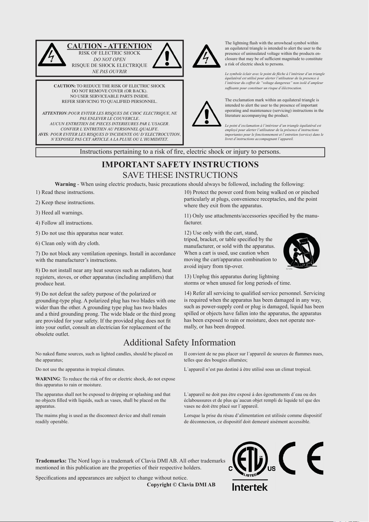
ORGAN PIANO PROGRAM SYNTH EXTERN EFFECTS
The Nord Stage 3 is designed to be a highly flexible, musically expressive and easy-to-use instrument. Let’s have a look at some of its key
features:
ORGAN SECTION
The dedicated Organ section uses our latest B3 tonewheel Organ
model, as found in the acclaimed Nord C2D Combo Organ.
The B3 model is based on the analysis of the signals generated by
each of the 91 spinning discs inside several original instruments, and
painstaking work on understanding exactly how all the original components interact with each other. The virtual circuitry reacts not only
to the settings on the panel but also during the real time performance.
The Stage 3 will faithfully reproduce the important foldback and energy
robbing characteristics; the latter will produce the gentle compression effect that makes those lovely smears absolutely wonderful. The
3 tonewheel modes allow for switching from a clean, factory spec’d
instrument to a worn and battered workhorse.
We have also created carefully modelled emulations of two of the most
famous transistor organs from the 1960’s; the Vox Continental and the
Farf (Farfisa) Compact. Alongside the organ’s themselves, the Nord
Stage 3 features a rotar y speaker simulation derived from the Nord
C2D. Incorporating the acoustic variations that occur as a physical
rotating spreads the sound around in a room, they bring the Stage 3’s
organs to life with remarkable realism. In terms of control, the 88 and
76 key model utilize our tried-and-true digital LED drawbars, whereas
the 73 key Compact model is equipped with physical drawbars.
Finally, there are two distinct Pipe Organ models including a “Principal”
Pipe model with two variations, delivering a wide range of versatile
pipe/church organ sounds.
PIANO SECTION
The Nord Stage 3 Piano section, with its 2 GB of internal memory,
delivers a stunning range of piano and keyboard sounds. Piano sounds
are divided into six different types including both classic Grand, Upright and Electric pianos as well as Digital piano and preconfigured
Layer sounds.
NORD PIANO LIBRARY
The Nord Stage 3 benefits from the sounds found in the ever-growing
Nord Piano Librar y. We spend a lot of time and effort on expanding
the palette of available sounds, ranging from state-of-the-art concert
grand pianos to characterful uprights, historical instruments, electric
pianos and more.
New sounds are regularly made available free of charge on the
www.nordkeyboards.com website.
STRING RESONANCE
String resonance is a physical phenomenon which occurs inside ever y
acoustic piano when strings, or parts of strings, resonate at their fundamental or harmonic frequencies as other strings are being played.
When String Resonance is turned on, played notes will affect each other to reproduce the acoustic interactions that occur inside an acoustic
grand or upright piano.
NORD TRIPLE PEDAL
The Nord Stage 3 is compatible with the Nord Triple Pedal which unlocks additional functionality within the Piano section.
This section is described in detail in the Organ chapter, beginning on
page 17.
The right pedal is the sustain pedal. When operated, all notes being
played will sustain until the pedal is released again. It also adds dynamic control of the mechanical “pedal noise” during operation and
enables dynamic “half-pedaling” techniques.
Page 9

2. OVERVIEW | 9
The left pedal is the soft pedal, also known as the Una Corda. When
applied, all notes will be slightly lower in volume and have a softer, more
subdued, tone quality.
In the middle is the Sostenuto pedal. Notes that are held when the
pedal is pressed down will “have their dampers raised” and keep sustaining, while subsequent notes will not be sustained.
PEDAL NOISE
When the sustain pedal is operated on an acoustic grand or upright
piano, many different sounds are produced by the mechanical components of that instrument’s pedal mechanism. Your Nord Stage 3
reproduces many of these natural sounds. When the sustain pedal is
pressed down, lifting the dampers from the strings, a beautiful sizzle
can be heard.
When the pedal is released, the dampers are returned to the strings,
which creates a different, muted type of sound.
PIANO AND CLAV EQ
A quick method for altering the character of the current piano sound is
to use the Piano and Clav EQ settings. The Clav settings are designed
to emulate those of the original instrument, while the Piano settings
are designed specifically with piano players in mind - instantly making
a sound softer, brighter or more mid-focused, depending on what the
song calls for.
high- and band-pass filters, the Stage 3 provides an emulated transistor low pass filter and a powerful combined low-pass/high-pass filter.
With both Amp and Modulation envelopes, an LFO and Unison control, the Stage 3’s synth capabilities are powerful, and provide virtually
limitless possibilites in terms of stunning on-stage sounds.
There’s an in-depth description of this section in the Synth chapter,
beginning on page 31.
EXTERN SECTION
The Nord Stage 3 delivers powerful capabilities as a MIDI controller,
especially when using the dedicated Extern section. Extern can be
turned on and off and assigned to keyboard zones just like the internal
sound engines, but specializes in controlling external gear - computers, synth modules etc. - over MIDI.
This section is described in detail in the Extern chapter, beginning on
pa g e 41.
EFFECTS SECTION
A wide array of classic effects are at your fingertips, within the comprehensive Effects section:
This section is further described in the Piano chapter, beginning on
page 21.
PROGRAM SECTION
A program on the Nord Stage 3 contains settings for all sound engines
and effects. The center area of the instrument - the Program section is where programs are navigated and stored, and various performance
features and settings menus are accessed. Importantly, this is also
where the two Panel buttons are located, used for switching between
the two independent panels available within each program.
This section is described in detail in the Program chapter, beginning on
page 25.
SYNTH SECTION
The Nord Stage 3’s powerful synthesizer engine is based on the acclaimed Nord Lead A1. In addition to Classic waveforms and digital
Waves and F-Waves (formants), the Stage 3 Synth can be used for all
sorts of Sample based sounds. It also features a S-Wave (superwave)
category suitable for those massive, multi-oscillator, sounds that can
not be created by other means. The large number of oscillator configurations allows for a multitude of single or dual oscillator setups, waveshaping, frequency modulation and more. An OLED display dedicated
to the Synth section provides a clear overview of its current setup.
The Effects 1 and 2 units provide all essential modulation effects such
as Tremolo, Chorus and Phaser, modeled after legendary stomp boxes
and effects units. The Delay effect can go anywhere from solidly vintage to modern and atmospheric sounding - with its Analog mode and
dedicated feedback filters.
Classic amplifier simulations, a versatile EQ and powerful, resonant
filters are available in the Amp Sim/EQ section, and a punchy Compressor with an extra tight “fast mode” helps keeping your performance in control. Finally, the lush Reverb - independently available
per panel - provides an array of small and large room simulations for
instant atmosphere.
Many of the effect parameters can be morph controlled – that is
addressed by the modulation wheel, control pedal or after touch –
which opens up for all kinds of creative, real-time interaction.
This section – and the Rotary Speaker – is described in detail in the
Effects chapter, beginning on page 43.
The Nord Sample Library gives Stage 3 owners access to a huge free
library of world-class sounds, including the famous vintage Mellotron
and Chamberlin samples. User-created samples can also be loaded
into the instrument, opening up a whole new creative world of sound.
In addition to the versatile 12 and 24 dB low-pass filters and the 12 dB
Page 10
10 | NORD STAGE 3 USER MANUAL OS V1.4X
GETTING STARTED
3
Let’s spend a few minutes getting acquainted with the most fundamental features of the Nord
Stage 3! In this chapter the most common scenarios and tasks will be described in a step-wise
fashion, hopefully serving as a good starting point for further editing and more advanced set-ups
as well.
HOOKING IT UP
1 Connect the Nord Stage 3 power cord to the unit and a mains power supply, connect the
2 Make sure to turn on the Nord Stage 3 first, before the sound system. Please be careful with
For more information on all the connections on the Stage 3, have a look in the Connections
section on page 57.
sustain pedal and a set of headphones or a sound system.
the output volume.
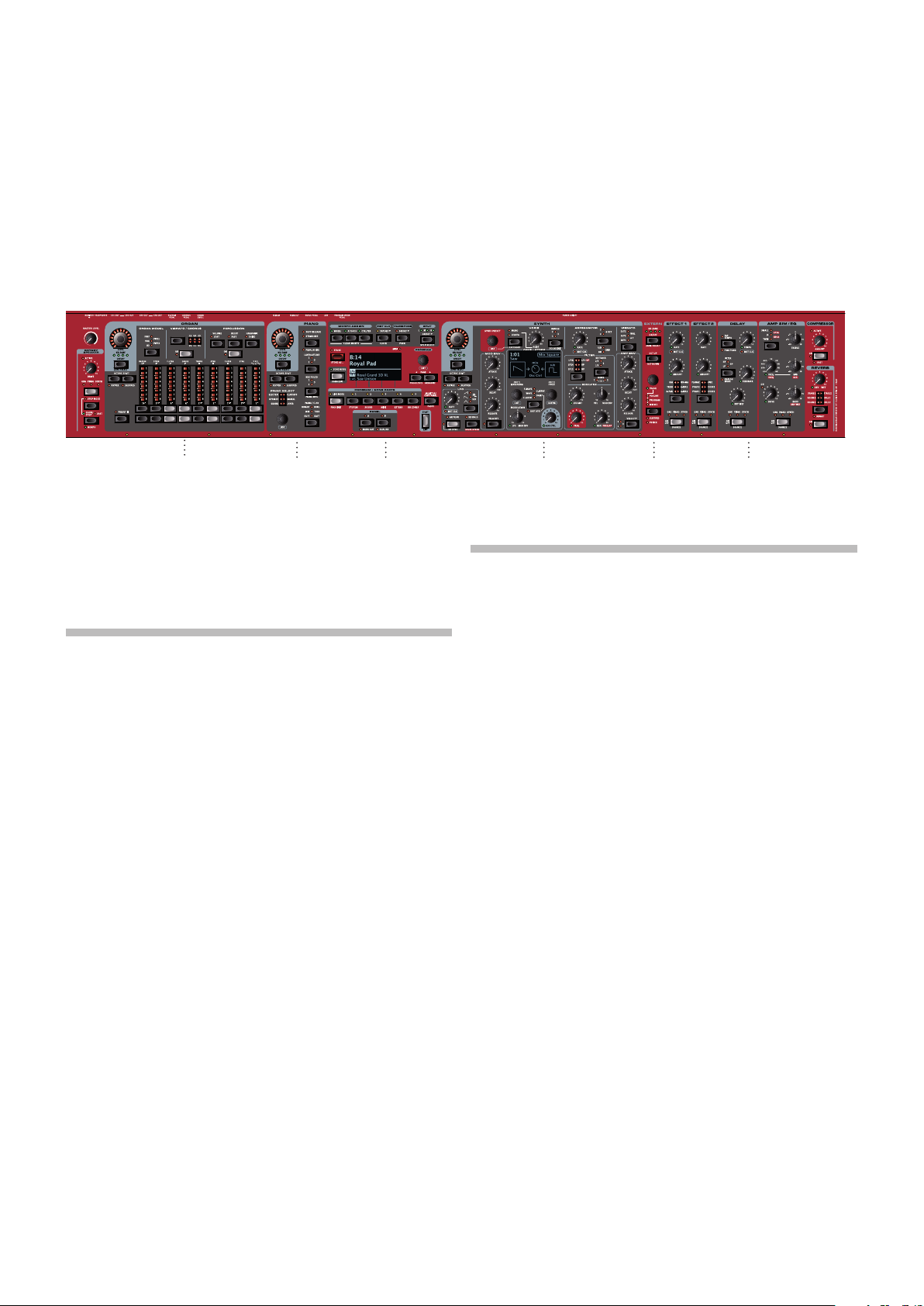
PROGRAMS
The Program area is located at the center of the panel and has an OLED display in the middle.
Complete settings of every parameter on the panel are stored in the program memory of the
Nord Stage 3, with enough room for 400 programs.
Programs are organized into 16 banks, labeled A-P. All programs can be edited and replaced
freely as desired.
M A complete set of the factory programs is available on the www.nordkeyboards.com web
site. This means that the program memory can always be restored to its original state.
SELECT A PROGRAM
1 Programs are selected by pressing any of the five PROGRAM buttons, located below the dis-
play. The PAGE 3/4 buttons are used to navigate program pages – a page being a group
of 5 programs. A Program bank on the Nord Stage 3 can contain up to 25 programs divided
into 5 program pages.
Some of the factory programs are labeled with MW or AT. This indicates that the Mod Wheel
or Aftertouch has an active part in the sound and invites you to use these performance
features.
2 Programs can also be navigated by simply turning the PROGRAM dial.
Page 11
3. GETTING STARTED | 11
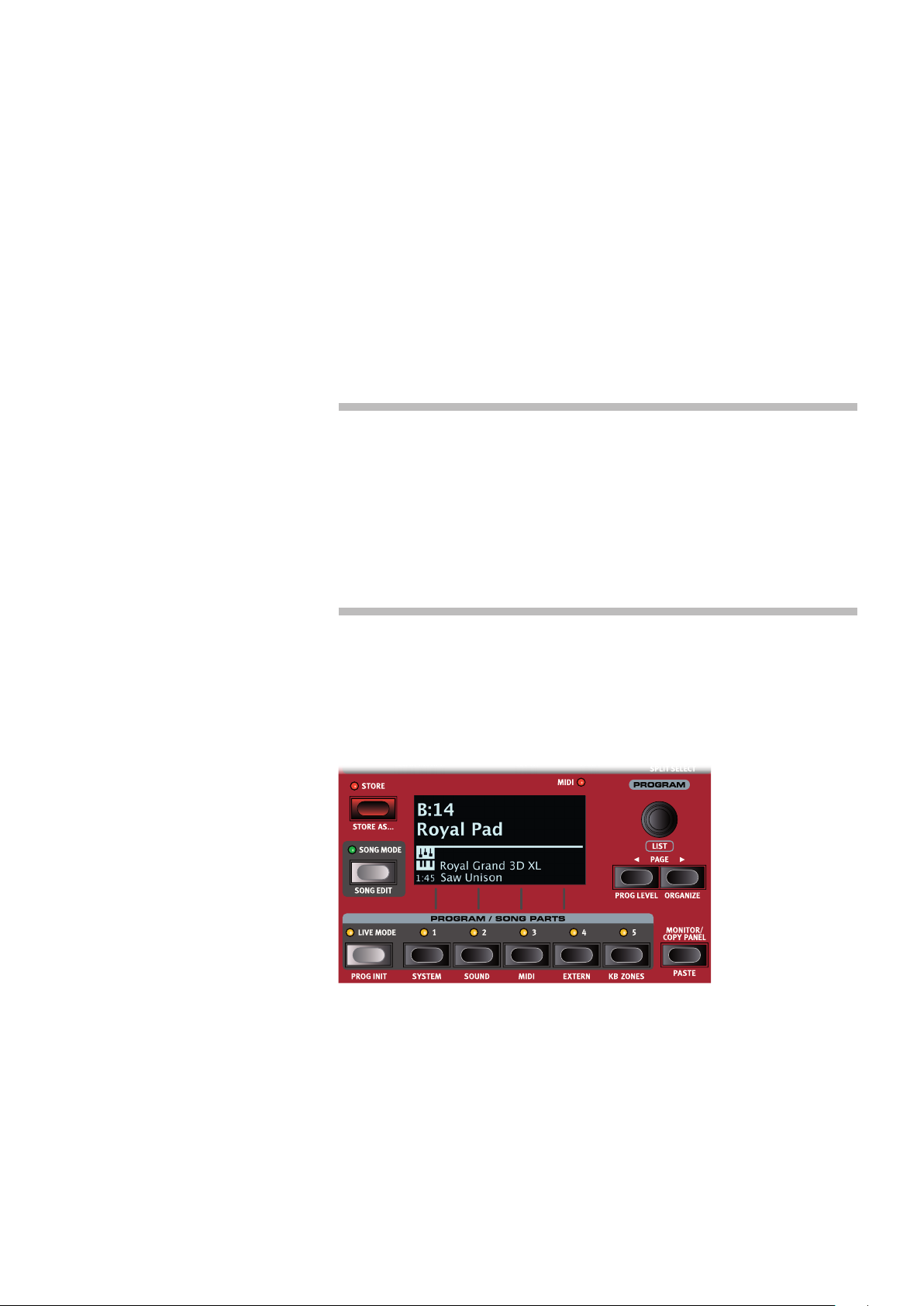
PANEL CONTROLS
DIALS AND KNOBS
The dials on the Nord Stage 3 are knobs without
any fixed start and stop positions, used for navigating parameters and settings in a step-wise fashion.
The PROGRAM dial is one such example. In this
manual, dials are sometimes also referred to as
encoders.
LEVEL dials are surrounded by LED indicators.
These provide a visual indication of the current value
for the associated parameter.
Potentiometer-type knobs are used for many
parameters on the Nord Stage 3. When a program
is loaded the physical positions of these knobs will
in most cases not correspond to the actual parameter values. As soon as a knob is turned however, its
associated parameter value will “snap” to the knob’s
position.
Knobs that can serve as a Morph destination are
equipped with green Morph LEDs. These are located at the bottom left of the knob, and will light up
if a Morph is targeting that parameter. Read more
about Morphs on page 25.
Hold the MONITOR button – found in the Program section – and
turn a knob to view the stored setting of a parameter in the display
without changing it.
BUTTONS
Selector buttons are used to select one setting
in an array. They have a set of round or triangular
LEDs to indicate its current setting. Press the
button several times to cycle through the possible
options.
ON/OFF buttons are used for activating a function
or a group of functions such as effects and have a
LED close to them to indicate the on/off status and
sometimes also the source or zone.
M The On/Off buttons of the Effects shown here also have a selector
functionality. Press once to turn the Effect on, and press immediately again to select the “next” source.
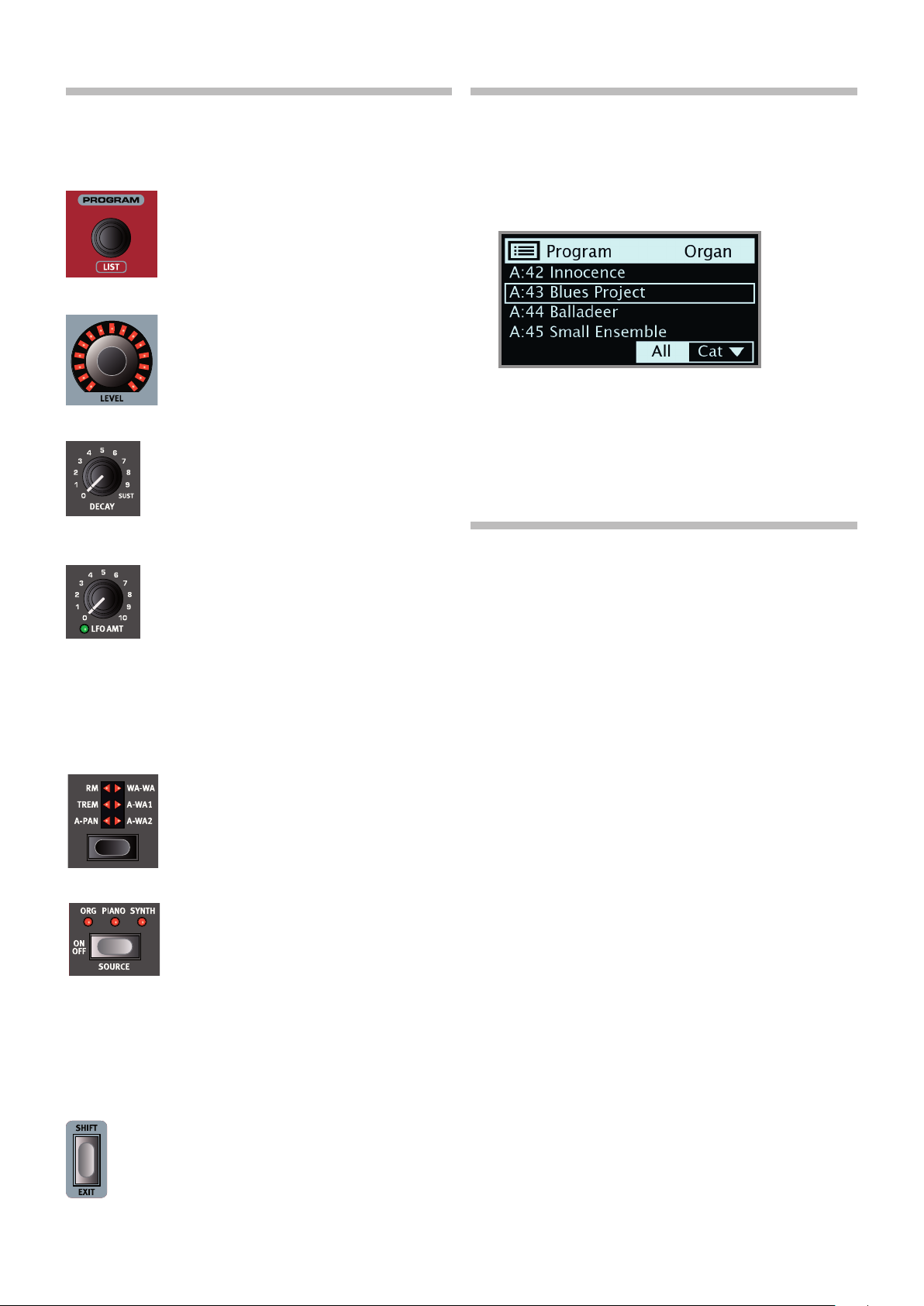
LIST VIEW
Any dial that has LIST written below it - such as the Program dial - can
be used to access a useful list view.
1 Press SHIFT and turn the PROGRAM dial to enter a list view of all the
Programs.
2 Browse to any program, using the PROGRAM dial. All 8 program
banks can be accessed when in List mode.
3 Press SHIFT again to EXIT the List view.
List views for the Piano, Synth Preset and Waveform dials function
in just the same way.
EDIT A PROGRAM
Editing a program is as easy as turning a knob or pressing a button, to
change an existing setting. Let’s give it a quick try:
1 Dial up Bank A, Program 1 (a piano based program) for this exer-
cise.
The controls for the Piano instrument are located immediately to the left
of the Program area on the panel. Notice that the Piano section of the
Program area display shows the name of the selected piano sound, and
that the six-way PIANO SELECT indicator is set to Grand.
SELECT A NEW PIANO SOUND
2 Turn the PIANO SELECT dial to browse the piano sounds. Sounds
are organized according to their type (for instance Grand and
Upright). The Piano Select LED indicator will show the type of the
currently selected sound.
3 Try selecting a piano sound from the LIST view, accessed by
pressing SHIFT and turning the PIANO SELECT dial. Use Shift again
to EXIT the list view.
Note that changing any parameter on the Nord Stage 3 panel causes an
“E” to appear next to the current program number in the display. This
indicates that the program has been edited but not yet saved into memory. If a new program is selected prior to performing a Store operation
any edits will be lost and the program will have its original settings the
next time it is loaded.
THE SHIFT BUTTON
Many panel controls on the Nord Stage 3 have a secondary
function, which is printed immediately below it. These additional functions are accessed by pressing and holding SHIFT
while operating the control.
The Shift button is also used to EXIT a menu or to cancel an
ongoing Store operation.
Page 12
12 | NORD STAGE 3 USER MANUAL OS V1.4X
TURN OFF MEMORY PROTECTION
When the Nord Stage 3 is shipped from factory its memory is protected
to prevent accidental overwriting of original programs. Memory protection can be turned off by toggling a setting located in the System menu.
1 Hold SHIFT and press the SYSTEM (Program 1) button below the
display.
2 Memory Protect is the first setting of the System menu. If the dis-
play shows a different setting, use the Page3button to navigate to
the Memory Protect setting.
3 Change this setting to Off by turning the PROGRAM dial.
4 Press EXIT (Shift button) to exit the System menu.
M This setting, like all other System settings, will be permanently
stored until it is changed again.
Read more about menu settings, starting at “System Menu” on page
52.
STORE A PROGRAM
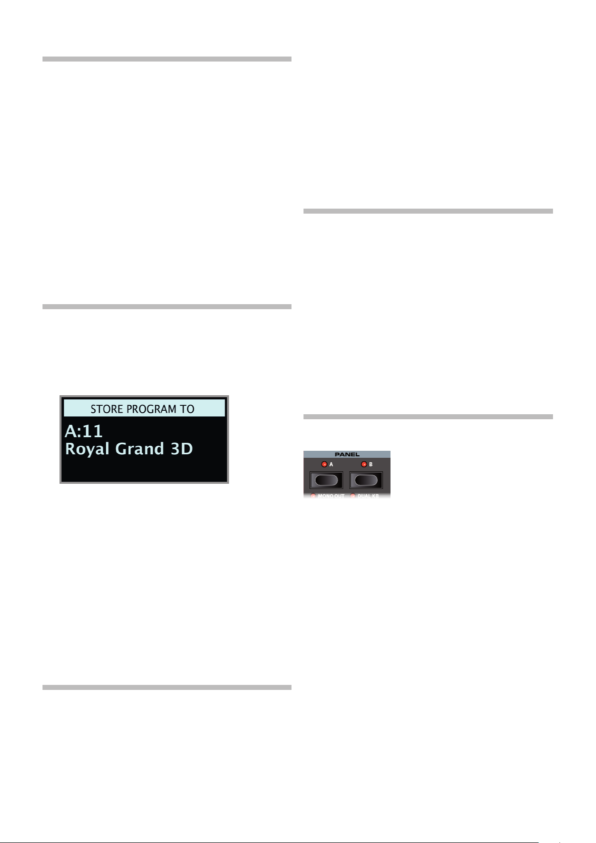
1 Press the STORE button to the left of the display once, to begin the
process of storing the current program.
2 The STORE LED will begin to flash and the display will ask you for
the location to where you want to store the program.
3 Select a different Live program and then return to the one that was
edited. Note that the edit was automatically stored.
If Live Mode is active and you decide to store the settings permanently
as a program in one of the Program banks, you can do so using the
standard Store methods (see above).
You can also store programs into any of the five Live Mode memory
locations, in which case the program settings will replace that current
Live Mode memory setting.
Press the Live Mode button again to exit Live Mode and return to the
Program banks.
ACTIVATE AN EFFECT
1 Activate the reverb by pressing the Reverb ON button.
2 Adjust the DRY / WET balance with the knob above the reverb
selector.
3 Activate the delay effect by pressing the Delay ON/OFF button once.
4 The LEDs above the button indicate which sound engine is routed
to the effect. Press SHIFT and the Delay SOURCE button until the
PIANO LED is lit, if it is not already.
Double-clicking the On Off / Source button is a shortcut for quickly
changing the source for any effects section.
5 Try the RATE, FEEDBACK, FILTER and MIX controls, to alter the char-
acter and intensity of the Delay effect.
3 If you want to store the edited version to the current location,
replacing the original, simply press STORE again. If not, use the dial
and/or PAGE 3/4 buttons to select a different location.
The program in the selected location becomes active on the
keyboard, allowing it to be auditioned before it is replaced by the
program being stored.
4 When you have found a suitable location for your program, press
STORE again to confirm the store operation.
M Press Shift/Exit once to abort an ongoing Store process if you
change your mind.
Read more about Store and how to name a program in the Program
chapter, on page 28.
LIVE MODE
The five LIVE programs differ from other programs in that all edits made
to them are instantly stored - without the need for a manual Store
operation.
1 Press LIVE MODE and use the five PROGRAM buttons to navigate
the five Live programs.
2 Make an edit, such as activating one of the effects sections, to one
of the programs.
THE TWO PANELS
The Panel A and Panel B buttons give instant access to two complete
instances of the features on the physical panel. There can be one complete Organ/Piano/Synth/Extern/Effects setup on Panel A, and another
complete setup on Panel B.
This allows for easy back-and-forth switching between two different
sounds, or for complex programs with up to two organ settings, two
different pianos and two different synthesizers. The two panels can be
combined either as layers or as split keyboard arrangements. Let’s set
up a split and then expand it with an additional layer combination.
CREATE A SPLIT
1 Make sure that only Panel A is active and that only the Piano sec-
tion is turned on.
2 To activate Split mode, press the SPLIT ON/SET button, located in
the top row above the Program area display.
3 To adjust the position of the Split point(s), press and hold the SPLIT
ON/SET button, located in the top row above the Program area
display.
M The “6“ symbol associated with this button indicates that one of
its functions - SET - is accessed by keeping the button pressed
down.
4 There are two settings for each split point; position and width. If
the display says “Split Width Middle” press the Program 4 button,
Page 13
corresponding to the 3symbol in the display, to instead show the Split Position settings. Set
the Middle split point to C4 using the dial.
5 Make sure that the other two split points (Low and High) are set to “Off”, accessed by press-
ing the Program 1 and 3 buttons respectively.
The keyboard is now divided into two zones, the split point being indicated with a green LED
above the keyboard. The M LED above the SPLIT ON/SET button will also be lit, indicating both
that Split is turned on, and that only the Mid split point is active.
ASSIGN THE PIANO TO THE UPPER ZONE
6 Hold SHIFT and press the Piano KB ZONE SELECT button repeatedly until only LED’s 3 and 4
are lit.
This assigns the Piano to the upper zone of the keyboard. Feel free to use the OCTAVE SHIFT
buttons in the Piano section for accessing a different range of the piano sound.
SET THE SYNTH TO THE LOWER ZONE
7 Turn ON the Synth section. Hold SHIFT and press Synth KB ZONE SELECT until only LED’s 1
and 2 are lit. This will activate the synth and assign it to the lower half of the keyboard.
M By using all three split points, Low, Mid and High, it is possible to divide the keyboard into a
total of four distinct zones, all of which can have any or all of the six sound engines and two
Extern sections assigned to it.
3. GETTING STARTED | 13
LOAD A SYNTH PRESET
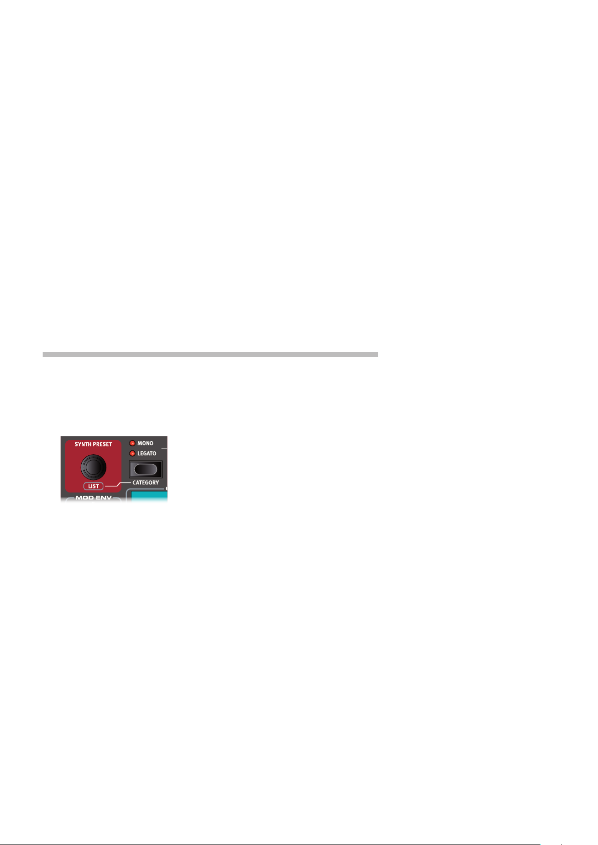
1 Turn the SYNTH PRESET dial and select any of the Synth presets from the 8 User preset
banks - perhaps a Bass Synth sound. Note that the location and name of the preset is
displayed at the bottom of the Program area display. The Synth display will at all times show
the currently active oscillator settings.
All the synthesizer parameters on the panel can be adjusted, even when using a preset as a
starting point. An in-depth description of these parameters can be found in the Synth reference
chapter, starting at page 31.
To view a parameter setting without changing it, hold the Monitor button and turn the pa-
rameter’s knob.
CREATE A LAYER
Let’s add a third sound to the Synth/Piano split we just created.
1 Activate Panel B by pressing the PANEL B button, giving access to a second set of sound
engines and effects.
2 Make sure that only the Synth section is active: Press SHIFT + PROG INIT and select Synth
from the display by pressing Program button 4.
The Prog Init function is used for quickly initializing the current panel in a manner which
suits the type of program which should be created, and will disable all sections and reset all
parameters that should not be used.
3 Use the SYNTH PRESET dial to select a sound which should be layered upon the previously
set up split.
ACTIVATE BOTH PANELS
4 Press both the PANEL A and PANEL B buttons simultaneously to create a layer with the
Page 14
14 | NORD STAGE 3 USER MANUAL OS V1.4X
The flashing panel LED (A or B) indicates which panel is currently focused for editing on the panel. Press the other Panel button to shift this focus to the other panel.
SET UP A SPLIT CROSS-FADE (SPLIT WIDTH)
As a final step, let’s adjust the split point so that the split Synth and Piano sounds will transition
gradually between one another:
5 Again, press and hold the SPLIT ON/SET button, located in the top row above the Program
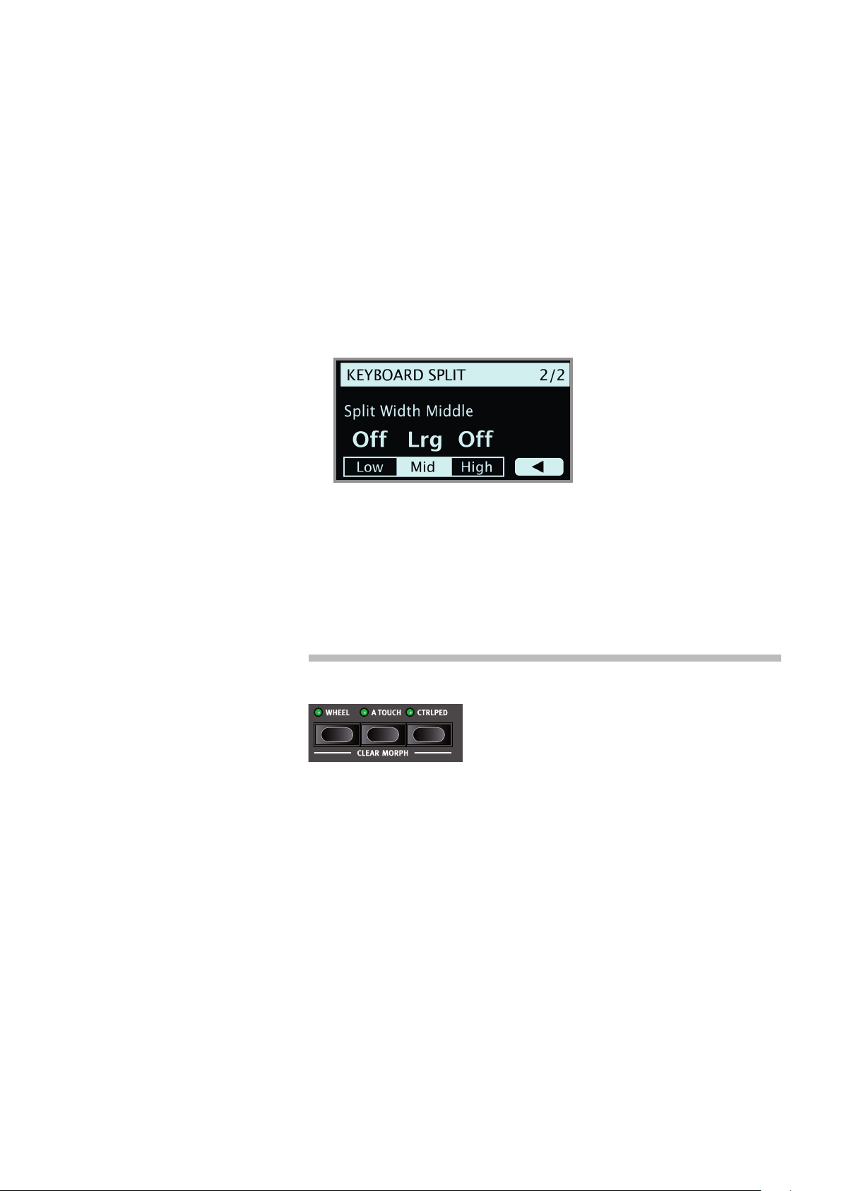
6 Press the Program 4 button, corresponding to the 4 symbol in the display. The Split width
7 Select the Mid split point and set it to “Lrg” by turning the dial. Let go of the SPLIT ON/SET
sounds from both panels. Panel A now contains the Synth/Piano split while the Panel B
Synth sound is layered on top.
area display.
for each split point can now be adjusted.
button.
Playing across the Split point now will “cross-fade” between the lower and the upper sound.
The Extern section can also be part of a split or layer scenario, e.g. if an external unit should
be controlled from just one zone on the keyboard. Note that the Split width setting will not
apply to the Extern section.
To turn off a panel combination, hold down the Panel button you wish to keep and then press the
other Panel button.
MORPHS
The modulation wheel, a connected control pedal or the keyboard aftertouch can be used to alter one or several parameters while playing. This is achieved by using morphs. In short,
this is done by selecting a a source (the physical controller) a
destination parameter and the parameter range included in the
morph.
1 We will now morph the drawbars with the wheel, so start by making sure that the Organ
section is turned On.
2 Make sure that the B3 model is active and “pull out” the first three drawbars on the left (Sub,
Sub3 and Fund) by pressing the corresponding lower drawbar buttons, or by actually pulling
the drawbars if using the Nord Stage 3 Compact model.
3 Press and hold the WHEEL button in the Morph Assign group, above the Program area dial.
4 Pull out the four right-most drawbars all the way. The indicators will show single LEDs to
indicate how much the Morph will affect the parameter.
5 Let go of the Morph WHEEL button. Play a few notes or chords, while moving the modulation
wheel.
As the wheel moves, the drawbars are pulled out and the sound changes accordingly.
One Morph source (Wheel, Control Pedal or Aftertouch) can control several parameters at
once.
A Morph source can increase one parameter’s value while decreasing the value of another
at the same time. This makes it possible, for example, to crossfade between instruments.
Read more about the Morph functionality on page 25.
Page 15
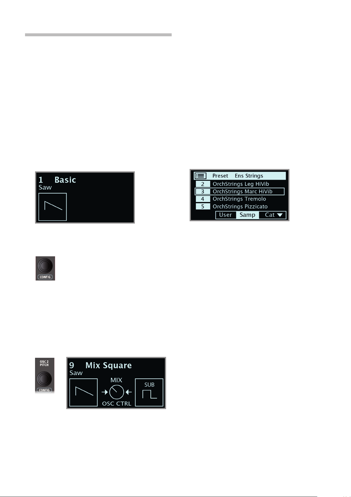
THE SYNTHESIZER
Let’s have a look at some of the features of the Stage 3 Synthesizer, beginning with how to set up a sound using Classic, “analog” waveforms.
1 Make sure the Synth section is active, by pressing the Synth ON
button, or by using PROG INIT (Shift + Live Mode) and selecting
Synth from the display.
2 In order to start off from a “blank slate”, let’s initialize the synthesizer
to its default settings by pressing SOUND INIT (Shift + Unison) and
then Init using the display soft button.
3 Make sure the Waveform selector under the display is set to CLAS-
SIC. Turn the OSC1/WAVEFORM dial until the sawtooth waveform is
selected.
4 Note that the right half of the display is currently empty. We are now
using a Basic, single oscillator, configuration which means that the
OSC CTRL knob has no impact on the sound. Let’s choose a
different configuration:
3. GETTING STARTED | 15
LOADING AND ADJUSTING A SAMPLE PRESET
Now let’s instead set up a string pad sound based on a sample, loaded
from the Sample Preset bank.
Apart from being selectable with the Osc1/Waveform dial, samples
are available as Read-Only presets within the Synth Preset banks.
When loaded from such a preset, some of the Synth settings –
such as Amp Envelope and Velocity – are automatically set to
values which suit that particular sample. All parameters can still be
adjusted manually as needed.
1 Activate the Synth Preset List view by pressing SHIFT and turning
the SYNTH PRESET dial.
2 Press the Samp soft button (Program 3 button) to isolate the Sam-
ple presets. Pressing down on the Cat soft button provides a list
of categories. Select an item from the list to show only the presets
within that particular category. When the Cat soft button is focused,
the PAGE 3/4 buttons can be used to quickly jump between
different categories.
5 Press SHIFT and turn the CONFIG dial to browse the different
configurations. Select the Mix Square configuration and let go of
the SHIFT button.
6 There are now two oscillators available, one set to sawtooth and
one set to square wave. Turn the OSC CTRL knob to mix the sound
of the two oscillators.
7 Turn the OSC2/PITCH dial (same as the Config dial - but without
Shift) of the Oscillator section and select a different pitch for the
square wave, indicated in semitone steps on the display. This way
the sound of the first oscillator (the sawtooth sound in this case)
can be combined with a sound of a different pitch, from one octave
below (“sub”, used in the example below) to several octaves above.
3 Select an appropriate Ensemble Strings sample by turning the
SYNTH PRESET dial (or the Program dial).
4 Play a few notes. To make a pad out of the sound we will want to
do a few tweaks. Let’s turn to the AMP ENV (Amplifier Envelope)
section:
5 While playing, adjust the Amp Env RELEASE control until a suitably
long tail is heard when releasing a note, perhaps at a value of
around 5.0.
6 Similarily, use the ATTACK control to create a softer and more
gradual onset of the notes you play. Again, a value of around 5.0
may be suitable.
7 To finalize the string pad, adjust the FILTER FREQ to give the sound
a softer character. A value of around 6.0 could be a good starting
point.
M Since we are basing this example on a preset, you may want to set
the VEL/MOD ENV knob to 0 (12 o’clock) when trying out point 8
above, to reset any preset velocity behavior.
There are several ways to further enhance this basic string pad sound,
for instance by adding modulation or by using effects. Read more about
modulation options on page 32 and about effects, beginning on page
page 43.
Additional samples can be added to the Nord Stage 3 by using the Nord
Sound Manager software.
As a final step, let’s turn to the Filter section for some adjustments:
8 Turn the Filter FREQ knob counter-clockwise, and notice how the
sound is gradually subdued. Repeat this with all FILTER TYPE set-
tings, paying attention to how they each have a different effect on
how the sound is shaped.
M Read more about the Filter Types, and other settings in the Filter
section, beginning on page 35.
You can store a tweaked synthesizer sound as a preset, by press-
ing Shift and the Store Synth button.
Page 16

16 | NORD STAGE 3 USER MANUAL OS V1.4X
THE ARPEGGIATOR
As a final exercise, let’s create a sound using the Synth section and its
arpeggiator.
1 Make sure that only the Synth section is turned on and perform a
SOUND INIT (Shift + Unison). Set the Amp Env ATTACK time to 0,
the DECAY to around 3, select a sawtooth waveform and open up
the filter a little bit. This will produce a percussive sound.
2 Press ARP RUN, play a chord on the keyboard and turn the Arpeg-
giator Rate knob. This will play the notes that are held down, one
after the other in a repeating fashion.
MASTER CLOCK
Now that we have an arpeggio going, let’s try the Master Clock feature
to synchronize the arpeggio and to bring in an effect as well.
1 Hold SHIFT and turn the Arpeggiator RATE knob to lock the arpeg-
gio to the Master Clock, the MST CLK LED lights up.
2 Press down on the Mst Clk TAP/SET button in the Program area to
dial in a tempo with the PROGRAM Dial. You could also press CLOCK
(Shift + Tap/Set) to view and adjust Master Clock settings without
having to keep the button pressed down. The display will indicate
the BPM. Set this to 130 BPM for this exercise. Release the button
to exit, or press EXIT (Shift) if in “Clock” mode.
Tap four times on the Mst Clk button to set the tempo on the fly.
3 Press SHIFT and the Arpeggiator selector button to select a differ-
ent direction.
When no direction LED is lit, the direction is Up, from the lowest
key and up to the highest and then it starts over again. The other
directions are DN (down), UP/DN (up and down) and RD (random).
4 Press the selector button repeatedly to select a range.
When none of the range-LEDs are lit, the range is exactly the
keys that are held down. A setting of 2 OCT extends the range by
transposing the arpeggio one octave up and plays this octave after
the initial octave, 3 OCT adds yet another octave and 4 OCT gives a
range of four octaves.
5 Press the KB HOLD button to keep the arpeggio going without the
need for pressing the keys.
3 Turn the Arpeggio RATE knob to select the meter subdivision (or
note values) that the arpeggio should play. The setting is shown
in the Program area display as the knob is being turned. Notice
how 1/4 is half the “speed “ of 1/8. A “T” after a numerical value
indicates triplets. Set the subdivision to 1/8.
4 Turn on the DELAY effect and make sure that the source is set to
Synth by pressing the SOURCE button repeatedly until the Synth
LED lights up.
If you carefully adjust the delay time, you could match it to fit the
rhythm of the arpeggio, but there is another way. Let’s synchronize
the delay to the same clock as the arpeggio.
5 Hold SHIFT and turn the Delay TEMPO knob to activate Master
Clock for the Delay. The MST CLK LED lights up.
6 Turn the Delay TEMPO knob and again refer to the Program area
display to monitor the setting.
7 Try 1/16, which will be half the note value or twice the “speed” of
the arpeggio. Turn up the Amount knob up to but not beyond 12
o’clock to hear the delay taps together with the arpeggiated notes.
The arpeggio, the LFO on the synth, the Delay and the Effect 1 rate can
be synchronized to the Master Clock in this fashion.
What’s more, the Master Clock operates on both panels simultaneously
so you can control arpeggios, LFOs and effects on both Panel A and B.
Some of the units have division settings that are larger than 1/1 that
allows for sweeps that are longer that one bar. And you can of course
synchronize some functions, while leaving others free-running if you like.
Page 17
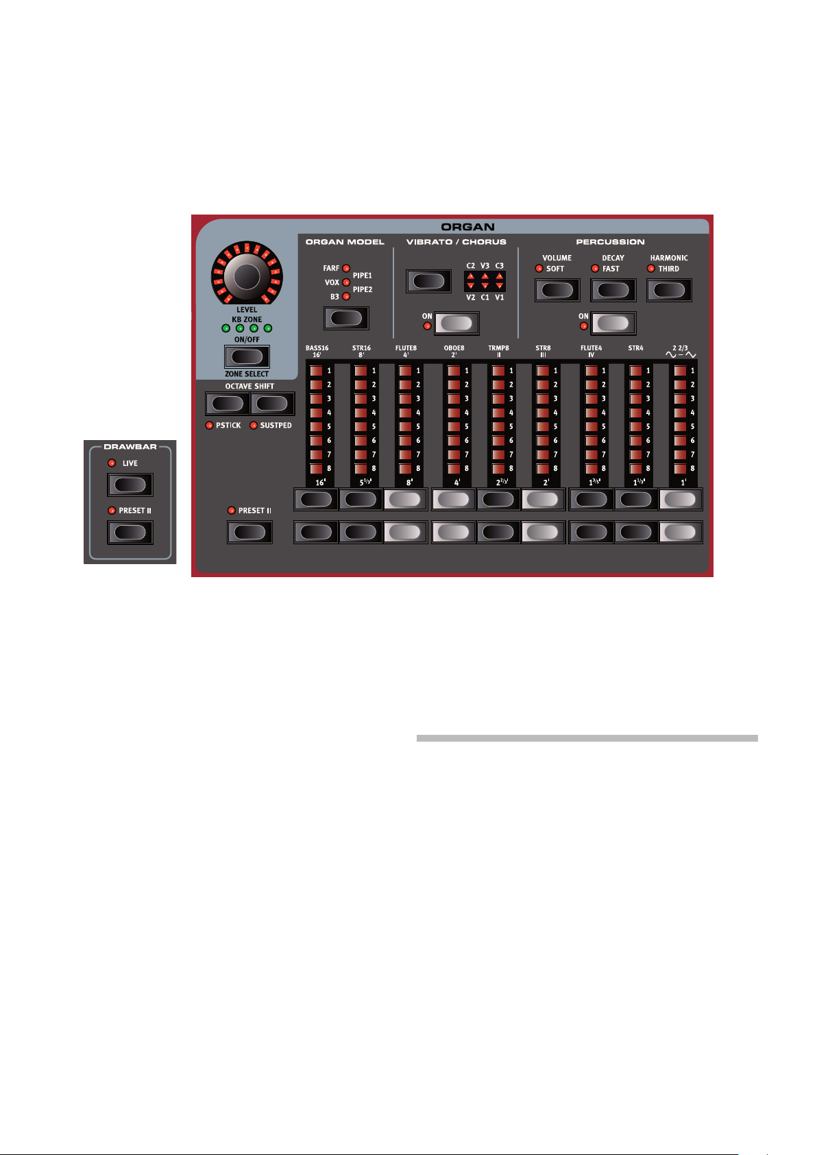
4. ORGAN | 17
ORGAN
4
Compact model
The Nord Stage 3 features five organ models, all digitally modeled; a
tonewheel/B3 organ, two transistor organs (Vox and Farfisa) and two
Pipe Organ models, including a “Principal Pipe” section. Different organ
models can be selected for Panel A and Panel B, allowing splits and
layers using different organ types to be realized.
M The Rotary effect – although conveniently located next to the Organ
section – is covered in the Effects chapter, see page 46.
ON/OFF, LEVEL AND ZONE SELECT
The Organ section is turned On or Off by pressing its ON/OFF button.
The morphable LEVEL encoder controls the sound output level of the
Organ.
Press ZONE SELECT (On/Off) with SHIFT, to assign the Organ to any of
the active keyboard zones. The green KB ZONE LEDs indicate which of
the zones the Organ section is assigned to. Read more about Split setups and keyboard zones on page 26.
OCTAVE SHIFT
Use OCTAVE SHIFT to transpose the Organ section up or down by oc-
taves (+/- 12 semitones). When assigned to the entire keyboard it can
be transposed one octave up or down. When assigned to a smaller
zone the available transpose values will vary, but always provide access
to the entire range of the Organ.
PSTICK AND SUSTPED
PSTICK (Shift + Octave Shift left/down button) turns on pitch stick func-
tionality for the Organ, in which case the Organ sound can be bent 2
semitones up and down, using the pitch stick.
SUSTPED (Shift + Octave Shift right/up button) activates any attached
sustain pedal for the Organ section. Read more on how to configure an
attached pedal in the Menus chapter, on page 52.
DRAWBARS AND BUTTONS
The drawbars on the Nord Stage 3 88 and 76 key versions are represented by buttons and LED chain graphs. The 73 key Compact version
uses “real” mechanical drawbars.
The digital drawbars behave similarly to their mechanical counterparts.
On the B3, Vox, Pipe and Sine models you “pull out” and “push in” the
drawbars using the drawbar buttons. With the Farf model, drawbar
buttons act as rocker switches, toggling each register on or off.
The buttons are special in the way that they auto-increment/decrement
the drawbar value when they are held down. If you hold a drawbar
button the corresponding drawbar setting will continue to increment or
decrement (within its range) until you release the button.
The drawbars can be Morph controlled, if you want to make dra-
matic changes with for example the Wheel or a control pedal.
While holding a drawbar button, you can press its “sibling” button to
momentarily auto-increment/decrement in the opposite direction.
M The Program section display also shows the current drawbar
settings for the Organ section - especially useful on the Compact
model where there are no drawbar LEDs.
Page 18
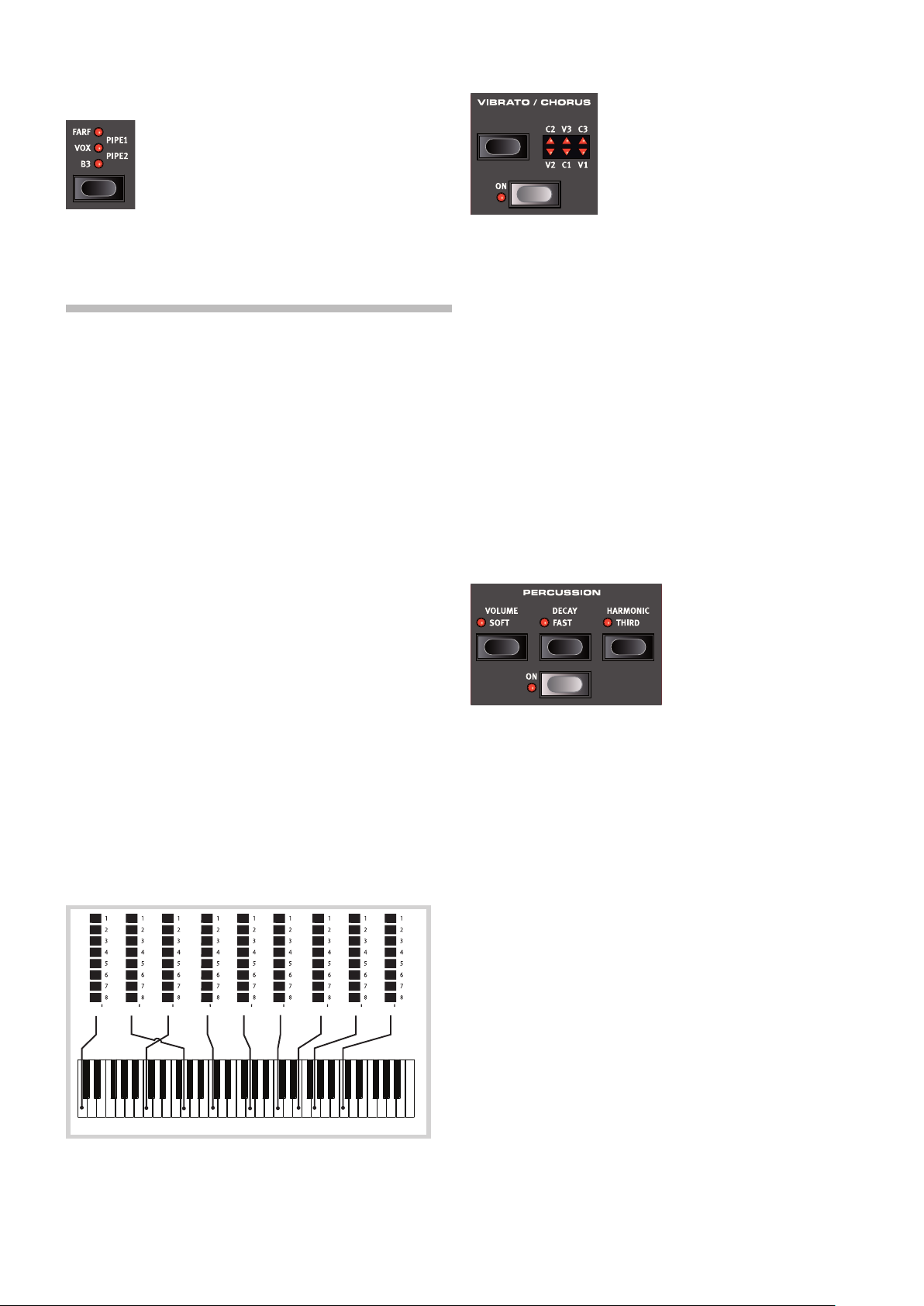
18 | NORD STAGE 3 USER MANUAL OS V1.4X
C3
16 5
⅓ ⅔ ⅗
8 4 2 1⅓1 1
2
SELECTING AN ORGAN MODEL
Use the ORGAN MODEL selector button to select your preferred Organ
model. The Pipe1 and Pipe2 settings are indicated by the upper and
lower LED pairs being lit respectively.
THE B3 MODEL
The B3 model is based on a digital model of the classic electro-mechanical tonewheel organ. This simulation utilizes innovative and advanced
methods to capture every nuance of the original sound. Here are some
examples:
• An extremely accurate digital model of the original chorus and vibrato
scanner.
• Modeling of the individual random contact bounces for each
harmonic.
• Modeling of the unique frequency characteristics of the built-in
pre-amplifier, which forms the “body” of the sound.
• Simulation of the energy robbing on the tone wheels that results in the
typical “compressed” sound.
• Authentic tuning of the tonewheels according to the original design.
• Extremely fast keyboard response.
• Full polyphony.
Three different types of choruses (C1 - C3) and three different types of
vibratos (V1 - V3) are available. Select one of these types by pressing
the Vibrato/Chorus selector button. The effect can be activated/deactivated for both panels individually by pressing the Vibrato/Chorus button
for the Panel A and Panel B “manuals”.
PERCUSSION
Press the PERCUSSION ON button to add an extra attack to the B3
sound by having a single envelope generator controlling either the 2nd
or 3rd harmonic.
The envelope “opens up” for a short moment in the beginning of the
sound when you press the key(s). The percussion is a single-triggered
non-legato effect. By “single-triggered” we mean that the percussion
is only present when you hit the keys when no other note is sounding.
In other words, if you play a note or a chord and then add more notes
without releasing the previously pressed keys, there will be no percussion effect in the new notes. You have to release all keys to be able to
play new notes with the percussion effect.
B3 DRAWBARS
The harmonic intervals for the tonewheel organ are printed on the panel
below the drawbars.
For basic drawbar operation, please refer to “Drawbars and Buttons”
on the previous page. Each drawbar represents a partial with a fixed
harmonic interval in relationship with the played note.
The illustration below shows the pitch interval among the nine drawbars when the key of C3 is played. Note that the 5 ⅓’ drawbar actually
is a 5th above the fundamental harmonic (8’) but in most situations is
perceived as sounding below it.
The VOLUME SOFT button toggles between Normal and Soft percussion
level. The DECAY FAST button toggles between Slow and Fast decay
times.
The HARMONIC THIRD button toggles between using the 2nd or 3rd
partial as the source for the percussion effect.
M The Percussion effect is only available for the B3 organ model.
KEY CLICK CONTROL
The key click produced by the random contact bounces is an important audio artifact in the original B3 instrument. This quickly became a
desirable effect amongst musicians. The click level can be adjusted in
the Sound menu, read more about this on page 53.
Do not forget to try out the three tonewheel modes that are also
available in the Sound menu. These will dramatically change the
sound of the B3 model from a squeaky clean unit to a battered, old
workhorse.
The original vibrato and chorus scanner in a tonewheel organ consists
of a modulated delay line in combination with a rotating scanner. For the
Vibrato effect, phase shift is applied to the signal. For the Chorus effect,
the phase-modulated signal is added to the original signal.
VIBRATO & CHORUS
Page 19
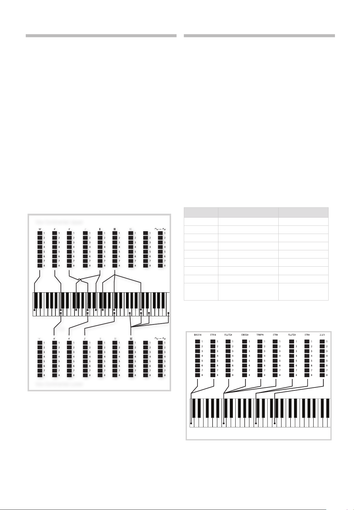
4. ORGAN | 19
THE VOX MODEL
The original Vox™ organ is probably the most famous of all the transistor based combo organs that emerged in the early 60’s. Transistor
technology made it possible to manufacture compact and portable
organ instruments. Compared to the mighty sound of tonewheel based
organs, transistor organs generally sounded reedier and weaker, but this
one had a distinctive sound character which together with the portability and cool design (inverse colored keyboard and chrome “Z-frame”
stand) made the instrument massively popular at the time. The sound is
timeless and recreated faithfully by the Nord Stage 3.
VOX DRAWBARS
The labels used for the Vox drawbars are printed on the row directly
above the drawbar LEDs.
For basic drawbar operation, please refer to “Drawbars and buttons” on
page 17.
The seven drawbars to the left control the level of each partial. Each partial has a fixed harmonic interval relating to the played note. The
illustration below shows the pitch interval of the drawbars when the key
of C3 is played. The intervals vary for the upper and lower manual on the
original instrument, but are identical on the Nord Stage 3.
Vox Continental Upper
THE FARF MODEL
The typical “buzzy” sound of this vintage instrument is one of the most
distinct and easily recognizable organ sounds ever created; yet it is actually possible to get quite a wide range of sounds out of the instrument.
Note that the voices aren’t supposed to replicate the instruments they
are named after, but rather to describe the basic tonal characteristic of
the voice: Flute = soft, Oboe = reedy, Trumpet = brassy etc.
FARF REGISTERS
The labels used for the FARF drawbars/registers are printed on the upper
row, above the drawbar LEDs or drawbars.
The drawbars act as on/off switches, or “register selectors” when the
Farf model is selected. Instead of drawbars, the original instrument used
rocker switches for selecting instrument voices (in reality different filter
settings) in various footage (octave) ranges. Drawbar LEDs 5-8 are lit up
for an activated voice, and drawbar LEDs 1-4 are lit up for a deactivated
voice. On the Nord Stage 3 Compact model, pulling the drawbars more
than half way out will activate the register.
As usual, the Program section display will show current drawbar settings
for the Organ section. The table below shows the original register name.
Drawbar Voice Panel Name
1 Bass 16 BASS16
2 Strings 16 STR16
3 Flute 8 FLUTE8
4 Oboe 8 OBOE8
5 Trumpet 8 TRMP8
6 Strings 8 STR8
7 Flute 4 FLUTE4
8 Strings 4 STR4
9 A bright voice, an octave
and a fifth above the
fundamental
2 2/3
C3
Vox Continental Lower
The rightmost drawbar controls the mix between a filtered signal sounding soft and dark, and an unfiltered signal sounding bright and intense.
VIBRATO
There are several types of vibrato and choruses available for the Vox
model, which is activated using the ON button in the Vibrato section.
The V3 setting is the one that is modeled after the original instrument.
The VX model’s Vibrato setting is common for both the Panel A and
Panel B Organ sections, although it can be turned on and off independently.
The illustration below shows the pitch interval between each voice when
the key of C3 is played. Though some voices have the same pitch, they
differ in tonal character.
C3
Page 20
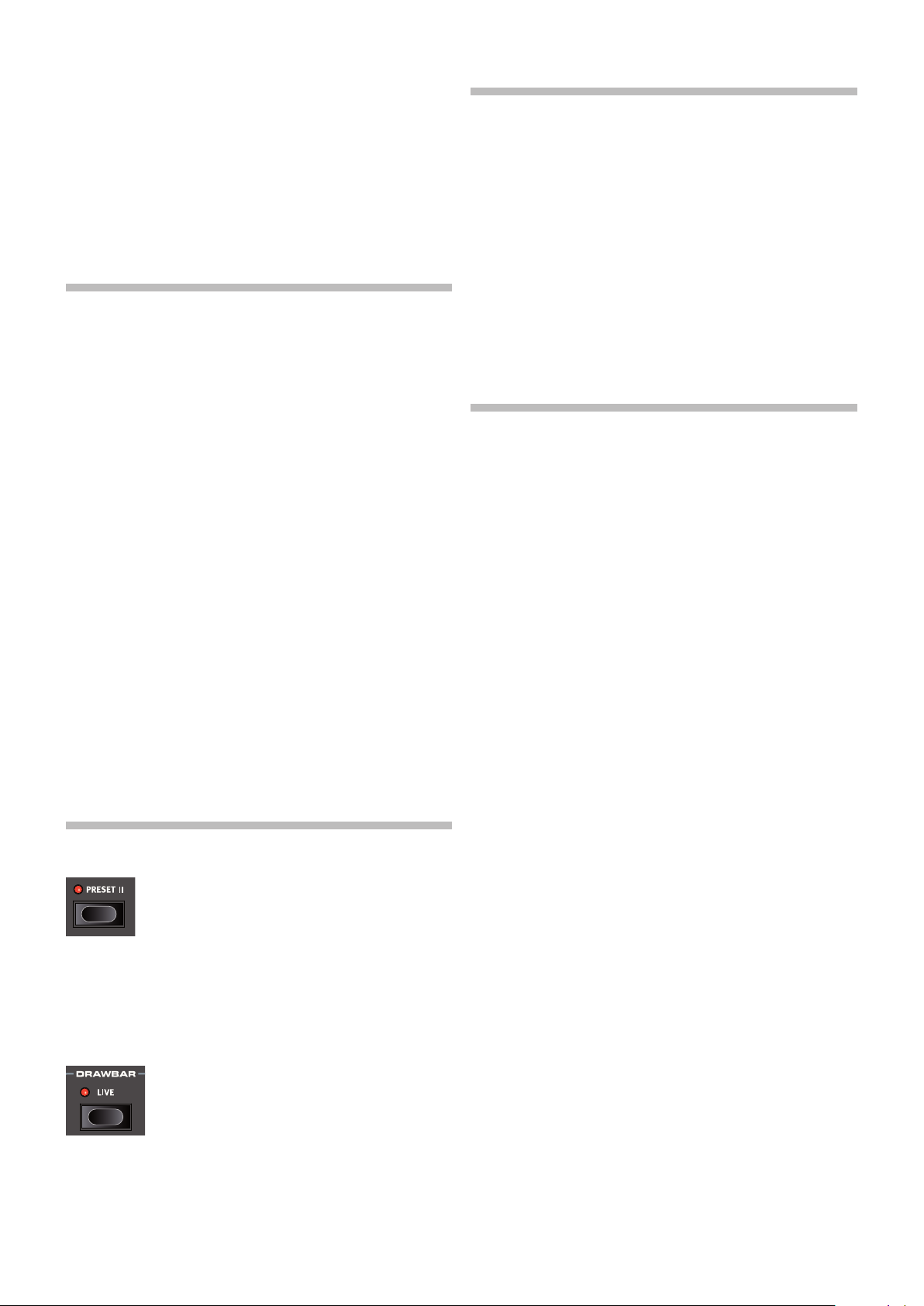
20 | NORD STAGE 3 USER MANUAL OS V1.4X
VIBRATO
The original instrument has two basic vibrato modes; “Light” and
“Heavy”, with different rates for each mode. There are several types of
vibrato and choruses available for the Farf model on the Nord Stage 3,
which are activated using the ON button in the Vibrato section.
The V1, V2 and the V3 settings are the ones that are modeled after
the original instrument’s. Note that the Farf vibrato is common for both
panels.
SWELL PEDAL
Swell is a characteristic organ feature, controlled from a continuous
pedal. Swell is not only a volume control - for the B3 it also changes
the character of the sound in a special way. To use Swell control on the
Nord Stage 3, simply plug in a standard expression pedal to the Organ
Swell input on the rear panel (see page 58) and configure the pedal
on the System Menu (see page 52).
An expression pedal connected to the Organ Swell input will control
Swell for all organ models.
PIPE ORGAN
PIPE 1
The PIPE1 organ model is not designed to imitate any existing instrument, but rather as a useful and appealing “all-purpose” organ, which
works equally well with or without Rotary speaker. In some ways its
sound is similar to that of the B3 organ – but without any of its electromechanical behaviors and artifacts.
PIPE 2
The PIPE2 organ model faithfully recreates a principal pipe section - the
sets of metal pipes, or ranks, that commonly make up the backbone of
a pipe or church organ. While other ranks may attempt to recreate the
sounds of other instruments (flutes, trumpets, strings etc.) the principal
sound is non-imitative and unique to the pipe organ.
Activating VIBRATO/CHORUS for the Pipe2 model will switch to a variation of the principal pipe organ, which is tuned with less precision. This
produces chorus-like effects, slight dissonances and arguably more
realism when combining registers.
PIPE 1&2 REGISTERS
If you have only one expression pedal, it can be used both as a generic
Control Pedal to control the Morph, and as a Swell Pedal - when
attached to the Control Pedal jack. This is also set up in the System
Menu.
ROTARY SPEAKER
The Rotary Speaker controls are logically placed next to the Organ
section. Its settings are described in detail in the Effects chapter on
page 46.
The pipe lengths available for both Pipe models correspond to those of
the B3 model, ranging from 16 feet to 1 foot.
ORGAN PRESET I & II
Two organ presets/settings can be stored within each
panel, for each organ model. This provides a quick way
of changing between two organ sound variations, without having to change programs or panels.
Change between Presets I & II by pressing the PRESET II button. A
preset stores the drawbar settings and the Vibrato/Percussion (on/off)
settings.
DRAWBAR LIVE (COMPACT MODEL)
The Nord Stage 3 Compact model has an additional Drawbar Live setting. With this setting active the
Organ will use the current positions of the physical
drawbars. The setting can be stored with a program,
meaning that the actual drawbar positions instantly will
be used as the program is loaded.
Page 21

5. PIANO | 21
PIANO
5
ON/OFF, LEVEL AND ZONE SELECT
The Piano section is turned On or Off by pressing its ON/OFF button. The
morphable LEVEL encoder controls the sound output level of the Piano.
Press ZONE SELECT (On/Off) with SHIFT, to assign the Piano to any of
the active keyboard zones. The green KB ZONE LEDs indicate which of
the zones the Piano section is assigned to. Read more about Split setups and keyboard zones on page 26.
OCTAVE SHIFT
Use OCTAVE SHIFT to transpose the Piano section up or down by oc-
taves (+/- 12 semitones). When assigned to the entire keyboard it can
be transposed one octave up or down. When assigned to a smaller
zone the available transpose values will vary, but always provide access
to the entire range of the Piano.
PSTICK AND SUSTPED
PSTICK (Shift + Octave Shift left/down button) turns on pitch stick functionality for the Piano, in which case the Piano sound can be bent 2
semitones up and down, using the pitch stick.
SUSTPED (Shift + Octave Shift right/up button) activates any attached
sustain pedal for the Piano section. Read more on how to configure an
attached pedal in the Menus chapter, on page 53.
ABOUT THE PIANO SOUNDS
The Pianos in the Nord Stage 3 are organized into six types. Each type
can contain several instrument models. New piano sounds can be
downloaded from the www.nordkeyboards.com website and added to
the Nord Stage 3 by using the Nord Sound Manager.
Right out of the box, the Nord Stage 3 features a fine collection of
carefully selected acoustic and electric pianos, digital piano sounds and
piano layers. A lot of effort was made to ensure a nuanced response
and sound, matching the original models as closely as possible. Each
piano has been sampled with a vast amount of velocity levels, which is
one reason why they all sound and feel so authentic.
The available memory size for piano sounds is 2 Gigabytes.
M When you download piano instruments with the Nord Sound
Manager, these will always automatically be placed into their corresponding type.
A program “knows” which piano to use by referencing to the type and
the model number. If a program references a piano that isn’t currently
downloaded onto the Nord Stage 3, the type LED will flash, and the
display will read “Piano not found”. If this happens, you can either navigate to another instrument Model in the selected (or any other) type
and select to use this piano instead, or use the Nord Sound Manager
application to download the missing instrument into the empty Model
location.
Page 22

22 | NORD STAGE 3 USER MANUAL OS V1.4X
ABOUT PIANO SIZE
Nord Piano Library sounds come in up to four different sizes. Below is
an overview of how they differ in functionality:
Sml Med Lrg XL
Stereo sampled
Detailed velocity mapping
String resonance for middle range
String resonance for entire range
Fully mapped keyboard
Small (Sml) piano files use the least amount of space in the piano memory as they do not contain any pedal-down String Resonance samples
at all.
The Medium (Med) versions include pedal-down String Resonance
samples for the important middle region of the range.
The Large (Lrg) versions have the pedal-down String Resonance samples all across the keyboard.
Many pianos are also available in an Extra Large (XL) version. These are
“fully mapped” across the keyboard, meaning that each key on the Nord
now matches its exact equivalent on the original instrument. This naturally imposes a substantial increase in size.
3 3 3 3
3 3 3 3
3
3 3
3
ABOUT THE CLAVINET
On the original Clavinet D6, different pick-up combinations were selected by pressing a number of rocker switches. This functionality is faithfully
simulated by the Nord Stage 3, which means that all original Clavinet D6
pickup selections are available.
PICK-UP TYPE DESCRIPTION
Clav Model A: Only the “neck” pick-up; a warmer, less bright sound.
Clav Model B: Only the “bridge” pick-up; a bright sound.
Clav Model C: Both pick-ups on and in phase; a very full sound.
Clav Model D: Both pick-ups 180 degrees out of phase; the fundamen-
tal is almost cancelled out and the sound becomes thin.
LIST VIEW
Pressing SHIFT and turning the PIANO SELECT dial activates the LIST
view for piano sounds.
The Piano list top row displays the current type name (“Grand” in this
case), the number of models of that type (9), and the index of the currently selected model (4).
PIANO SELECT
TYPE AND MODEL
Use the PIANO SELECT dial to choose which piano sound you want to
use. These are the six types into which all piano sounds are placed:
TYPE DESCRIPTION
Grand Acoustic and electric grand pianos
Upright Upright pianos
Electric Electric Pianos (tine and reed based)
Clav/Hps Clavinets and Harpsichords
Digital Digital piano sounds
Layer Layered piano sounds
M Pianos can not be moved from one type to another.
The list itself shows the currently selected model,
indicated by a rectangle, as well as the preceding
and following models.
KBD TOUCH
Pianos from the Nord Piano Libary typically have a
very wide dynamic range, and their dynamic response
can be adjusted according to what fits your personal
style or the context of your performance.
The default KBD TOUCH setting (all LEDs being off)
facilitates playing softly yet expressively. With each
increment of the Kbd Touch setting (1, 2 and 3) less effort is required to
play loudly.
PIANO INFO
Pressing SHIFT + PIANO INFO will display some additional info about the
currently selected model, such as its version number and its exact size.
STRING RES / SOFT RELEASE /
PEDAL NOISE
The triangular Piano Select LEDs indicate the type of the currently selected piano model. The name of the selected model is shown in the
bottom area of the Program area display, indicated by a keyboard icon.
SOFT RELEASE
Activating SOFT RELEASE will add a slightly longer and
less pronounced release to the piano sound. This
is equivalent to what happens when you adjust the
damper tension in an acoustic or an electromechan-
ical instrument. The added release is individual for
every note and responds dynamically to the force with
which you play.
Page 23

5. PIANO | 23
M Some Piano types, such as Clavinets and Harpsichords do not support the Soft Release
feature. In these cases the button will be disabled.
STRING RESONANCE
String Resonance refers to the acoustic phenomenon that occurs when strings, or parts of
strings, resonate at their fundamental or harmonic frequencies when other strings are played.
When STRING RES is turned on, all notes you play will affect each other to reproduce the wonderful acoustics that occurs inside an acoustic grand or upright piano.
You will also hear all the strings resonate if you press the sustain pedal and play some notes.
M If a piano is selected that isn’t compatible with the String Resonance feature, this function
will be disabled. This applies to e.g. the small (Sml) versions of the grand pianos and uprights, or the electric pianos.
PEDAL NOISE
PEDAL NOISE, (Shift + Soft Release/String Res) is available if the Nord Triple Pedal is connected
to the Nord Stage 3 (see below). When activated, the mechanical noise that occurrs with the
sustain pedal on an acoustic or electric piano will be recreated. The Nord Triple Pedal is dynamic,
its noise level being controlled by the force used when the sustain pedal is operated.
M If a piano is selected that is not compatible with the Pedal Noise feature, this function will be
disabled.
NORD TRIPLE PEDAL
The Nord Stage 3 is compatible with the Nord Triple Pedal, an optional accessory which is comprised of three pedals in one unit. This pedal unlocks additional features and sounds within the
Piano section of the Nord Stage 3.
M If using the Nord Triple Pedal, make sure the Sustain Pedal type is set to either Auto or Triple
in the System menu. See page 53 for details.
SUSTAIN AND HALF PEDALING
The right pedal is the sustain. On the Nord Triple Pedal this can be used with half pedaling techniques, achieved by pressing the pedal half way down. In this case the (virtual) dampers are only
half-raised, for a partially dampened sound.
SOSTENUTO
The middle Nord Triple Pedal is the sostenuto pedal. By using this, selected notes can be sustained, while other notes remain unaffected. Only the notes that are already held down when the
pedal is operated will sustain. Subsequent notes, played while keeping the pedal down, will not
be sustained.
SOFT PEDAL
The left pedal on the Nord Triple Pedal is the soft pedal, also known as the Una Corda. When it
is pressed down, all played notes will be slightly lower in volume and also have a slightly more
subdued tone quality.
Page 24

24 | NORD STAGE 3 USER MANUAL OS V1.4X
PIANO/CLAV EQ
PIANO EQ SETTINGS
Use the PIANO EQ settings to quickly alter the frequency content and character of the selected
piano sound – while keeping the EQ effects unit free for other tasks.
The SOFT setting will filter out much of the high frequency range, and emphasize parts of the low,
resulting in a subdued and mellow sound.
The MID mode de-emphasizes both high and low frequency ranges, making for a focused and
cutting sound with a prominent mid-range.
The BRIGHT mode emphasizes the high frequency range, producing a bright, brilliant sound
which is also useful for bringing out the “ping” in electric pianos.
CLAV EQ SETTINGS
An original Clavinet is equipped with 4 additional rocker switches, which control the onboard
EQ. Most of these settings combinations are available on the Nord Stage 3. Use the PIANO/CLAV
button to select your preferred combination of the filter settings.
LAYER DETUNE
If the Piano sections for Panel A and B are both active in a layer configuration, the LAYER DETUNE
feature can be used to detune the two piano sounds. There are three different degrees of detune,
1, 2 and 3, ranging from a subtle chorus-like effect to more extreme detuning.
M Layer Detune will only affect the piano sounds on Panel A and B – not other active sound
engines.
Page 25

6. PROGRAM | 25
PROGRAM
6
The PROGRAM section provides access to performance functions such
as recalling and storing programs, access to the Song and Live modes,
keyboard split functionality and more. This is also where menus containing System, Sound, MIDI and Extern settings are found. The menus and
their settings are covered in a separate chapter, starting on page 52.
The Program area features are all described in this chapter, beginning
with the top row.
MORPH ASSIGN
The Morph is a very powerful tool,
which allows for controlling several
parameters at once using one control
“source”. A foot pedal can be used
to control the level balance between
a piano and a synth sound, the wheel
to perform drawbar changes in a B3 sound, and increase the rate of a
selected effect by keyboard aftertouch – all at the same time.
The three MORPH ASSIGN buttons, WHEEL, A TOUCH, CTRLPED, represent the three available Morph Sources: the modulation wheel, keyboard
aftertouch, and control pedal.
A Morph is set up by holding down one of the Morph Assign buttons,
while at the same time moving a parameter control (for example a knob
or a drawbar) from the point where the morph should start to the point
where it should end. It is a good practice to have the parameter control
set to the desired start position before pressing down the morph assign
button. The display will show the start and stop values, as the morph is
being set up.
Several parameters can be adjusted while pressing down a Morph
Assign button, and additional morph destinations can be added after a
morph has been set up as well.
Double-clicking a Morph Assign button activates morph assign
latch mode, which allows for setting up morphs without keeping
the Morph Assign button pressed down. Press EXIT to leave the
morph assign latch mode.
MORPH DESTINATIONS
The following parameters are available as Morph destinations:
Organ Piano Synth Effects
Level Level Level Effect 1 Rate
Drawbars LFO Rate Effect 1 Amt
Rotary speed Osc Ctrl Effect 2 Amt
LFO Amount Delay Tempo
Filter Freq Delay Feedback
Resonance Delay Mix
Arp Rate EQ Mid / Filter Freq
Drive
Reverb Dry/Wet
Page 26

26 | NORD STAGE 3 USER MANUAL OS V1.4X
MORPH INDICATORS
All morphable parameters are equipped with some means to indicate
that a morph has been assigned to it, or that a morph is being performed. These are the three different types of indications used:
LED ENCODERS
The LEVEL controls of the Organ, Piano and Synth
sections feature a rotary LED encoder. These
provide a clear indication of the morph start and
end points as the morph is set up, and allows the
control to display its current value at all times as a
morph is being performed.
MORPH LEDS
Most morphable parameters are equipped with a
“morph LED” which will be lit with a green light after a
morph source has been assigned to the parameter.
DRAWBAR LEDS
If a drawbar has been selected as a morph destination, the drawbar
LEDs will adjust accordingly as a morph is being performed (except on
the Nord Stage 3 Compact model, which uses physical drawbars instead of drawbar LEDs).
CLEARING A MORPH
Hold SHIFT and press a MORPH ASSIGN button to clear all Morphs for
this source within the focused panel. To clear a particular assignment,
hold the Morph Assign button and operate the control to remove the
“gap” between the programmed setting and the Morph setting.
EXTERNAL SYNC
The Master Clock on the Stage 3 can be controlled by incoming MIDI
clock messages. This is an automatic behavior: As soon as the Stage 3
receives MIDI clock on the MIDI input or the USB MIDI input, the Master
Clock will be synchronized to the incoming external clock.
When the Master Clock is locked to an incoming clock, “external” will be
shown in the display if MST CLK is pressed, together with the incoming
tempo in BPM.
(KBS) KEYBOARD SYNC
On the Master Clock tempo/settings page, Keyboard Sync behavior can
be selected by pressing the KBS soft button.
Off: When set to Off the Master Clock will never be reset by playing the
keyboard.
On: When set to On the Master Clock will always be reset after lifting all
keys and then playing the keyboard again.
Soft: When set to Soft the Master Clock will only be reset if waiting
longer than one quarter note (in relation to the current tempo) to play the
keyboard, after all keys have been lifted.
TRANSPOSE ON/SET
The Nord Stage 3 can be transposed in semitone
steps on a per-program basis, with a range of +6/-6
semitones. Hold the Transpose button and set the
transposition by turning the Value Dial. Press the
Transpose button again to de-activate a transposition.
Transpose settings are saved and recalled as part of a program, and
always affect both panels of a program.
MST CLK
The Master Clock allows you to synchronize the Arpeggiator, the Synth
LFO, the Delay and Effects 1 Rate in the Nord Stage 3. Not only can
these be made to run in sync with each other; different subdivisions
can be set for all synced components, allowing for some great rhythmic
effects.
Tap the MST CLK button a minimum of four times to set a tempo,
expressed in BPM (beats per minute). Keep tapping the button to further
refine the tempo setting if needed.
Press CLOCK (Shift + Mst Clk) to bring up the Master Clock tempo and
settings page. Use the PROGRAM dial to set the tempo. Press EXIT
(Shift) when finished. The set tempo will be stored with the program, as
long as a Store operation is performed.
M Pressing down on the MST CLK button opens the Master Clock
tempo page while the button is pressed down, as indicated by the
“6“ symbol.
When the Master Clock tempo is set, you can select a subdivision of
that tempo for the various functions that can be synchronized to the
Master Clock. Any changes you make to the Master Clock tempo will be
followed by all the functions in the Stage 3 that are synchronized to it.
The subdivisions are described in greater detail in the sections covering
each syncable function, the Synth LFO and arpeggiator, Effect 1 and
Delay.
To set up a transpose that affects all programs, use the Global
Transpose parameter in the System Menu.
PANIC
Hold SHIFT and press the Transpose button to execute an internal “All
Notes Off” message and reset of some of the performance parameters.
This can for instance be used if notes get stuck during a MIDI or live
performance, or if all sound should quickly be eliminated for some other
reason.
SPLIT
The Nord Stage 3 keyboard can be split in up to four
keyboard zones; 1, 2, 3 and 4, separated by the three
available split points, Low (L), Mid (M) and High (H).
Any sound engine (Organ, Piano or Synth) can then
be assigned to any or all of these zones.
A single press on the Split ON/SET button will simply turn the the split
function on or off. Pressing down on the button, as indicated by the “6“
symbol, will open up the Keyboard Split position page in the display.
Pressing SHIFT and SPLIT SELECT will toggle between the different L, M
and H split point combinations.
Page 27

6. PROGRAM | 27
KEYBOARD SPLIT SETTINGS
After a split has been activated, use the ZONE SELECT buttons (accessed
with SHIFT) beneath each instrument’s (or the Extern’s) Value Dial to assign an instrument to one or more zones. The four Zone LEDs beneath
the instrument’s Level Rotary will indicate the assignment.
CHOOSING A SPLIT POSITION
The Keyboard Split position page allows for assigning each of the three
split points a keyboard split position, or for deactivating a split point by
setting it to Off. There are 10 keyboard split positions to choose from,
ranging from F2 to C7. To adjust a split point, give it focus by pressing
its corresponding soft button (Low, Mid or High), corresponding to the
three first PROGRAM buttons, and turn the dial.
LEDs are provided above the keyboard, indicating which split positions
are active at all times.
SPLIT WIDTH SETTINGS
Normally the transition between two keyboard zones is “straight”, in
that there is no overlap between the sounds selected for each zone. By
adjusting the Split Width setting for a split point, the sounds can instead
be mixed or “cross-faded” across the split point, producing a smoother
transition between the sounds.
To adjust Split Width, keep the ON/SET button held down and press the
4 soft button, corresponding to the PROGRAM 4 button. This will bring
up Keyboard Split width page, where the width or “cross-fade” range of
each split point can be set.
KEYBOARD ZONES EDITOR
Thee KB ZONES editor allows for a clear overview and easy set-up of
keyboard zones and how sound engines are assigned to them. A set-up
using the Organ (O), Piano (P), Synth (S) and Extern (E) sections on Panel A, and the Piano section of Panel B may look like the example below.
The position and length of each bar indicates which keyboard zone(s)
that section has been assigned to.
To adjust which zones a sound engine (or the Extern section) is assigned
to, the ON/OFF buttons for each section and the Zone soft buttons are
used in combination. As an example here is how to set up the Piano in
Panel B so that it covers zones 2 and 3:
1 Make sure the Piano section on Panel B is turned on.
2 Press SHIFT + KB ZONES (Program 5 button) to open the editor
window.
3 The display will indicate which zones the Piano sound is currently
assigned to. Unless a KB Split has been set up previously, this will
most likely be all four zones (the entire keyboard).
4 Press and hold the Piano ON/OFF button on Panel B and then
press the Zone 2 and 3 soft buttons (Program 2 and 3 buttons).
The Piano sound will now be assigned to Zone 2 and 3. Using our
previous example, this is what that will look like:
Select the split point to adjust by pressing its soft button (Low, Mid or
High) and turn the dial to change its setting.
Off: With the Off setting there will be no cross-fade between sounds at
the split point.
Sml: The Sml setting represents a width of 12 semitones, meaning that
the sound below the split point will reach 6 notes above it, after which it
will be completely faded out. Sounds above the split point will similarily
reach 6 notes below it.
Lrg: The Lrg setting provides a width of 24 semitones, 12 below the
split point and 12 above it.
M Both panels use the same KB Zone configuration. Instrument
assignments are individual for each panel.
You could also turn the Program dial, while holding down the
Piano On/Off button. This will scroll through all the possible Zone
combinations.
Depending on the Zone combination selected, the necessary Split
points will be assigned automatically. Their exact position and width
needs to be set from the SPLIT SET page however (see the previous
section).
Setting up the Organ, Synth and Extern sections is done in the same
way.
STORE
The STORE button is used for storing an edited
program or song to a location in the program banks.
Storing a program or song will overwrite the existing
data in the selected memory location. For how to store
Synth Presets, see page 34.
Page 28

28 | NORD STAGE 3 USER MANUAL OS V1.4X
M When the Nord Stage 3 is shipped from factory its memory is
protected, to avoid accidental overwriting of programs. To be able
to store Programs, The Memory Protect parameter needs to be
set to “Off” in the System menu. Read more on how to do this on
page 52. The Memory Protect function does not affect the Live
Mode memories or operations performed through the Nord Sound
Manager.
STORING AND NAMING A PROGRAM OR SONG
To store a program or Song without changing its name, proceed as
follows:
1 Press the STORE button once. The Store button will start blinking,
and the display will show the name of the program or Song, and its
location.
SONG MODE
The Nord Stage 3 features a dedicated Song Mode
which is used for referencing groups of programs,
according to how they are used within a live set list
or similar. Program references are referred to as song
parts, and a group of 5 song parts is referred to as a
song. There are a total of 8 banks of 50 songs each.
E It is important to note that songs do not contain copies of the pro-
grams and their data. This means that if a program is edited and
stored, all songs referencing it will make use of the edited program.
When SONG MODE is pressed, the last active song will be selected and
the Song Mode LED will light up. The display will show the location and
name of the Song, along with the currently focused program within the
Song.
Navigating parts within a song is as easy as pressing one of the SONG
PARTS 1-5 buttons. Songs are changed either by pressing the PAGE
3/4 buttons or by turning the PROGRAM dial.
Song parts can also be changed by using an attached Program
Up/Dn pedal.
2 To select a different store location use the dial and/or PAGE 3/4
buttons. A program can also be stored to one of the five Live
program locations. This is done by pressing the LIVE MODE button
and then selecting the desired Live program button. The program
at the selected store location can always be auditioned by playing
the keyboard.
M To cancel an ongoing Store operation, press EXIT.
3 When a suitable location has been selected, press STORE again to
confirm the operation.
STORE AS
1 To store and name your program or Song, press STORE AS (Shift +
Store).
2 Hold down the ABC soft button to bring up a row of alphanumeric
characters and use the dial to select a character for the current
position. Letting go of the ABC button moves the cursor to the
next position. The dial or PAGE 3/4buttons can be used to move
the cursor freely. The Ins soft button is used for inserting a blank
space at the current position and the Del soft button is used for
deleting the currently selected character.
SONG EDIT
To select which programs should be part of a song, activate SONG EDIT
(Shift + Song Mode), indicated both in the display and by the Song
Mode LED and current Program LED blinking.
To then change which program is referenced from a song part, simply
press the corresponding SONG PARTS button, and turn the dial. To return from Song Edit mode, press EXIT.
E Any changes made in Song Edit mode need to be stored through a
Store operation to take effect.
STORING A SONG
Storing and naming a Song is done in exactly the same way as storing
and naming programs, see the previous Store section for details.
STORING EDITED PROGRAMS
Program edits that have been made when in Song Mode will not be
stored when a song is stored, as the song only contains references to
program locations. To store an edited program, first exit Song Mode by
pressing SONG MODE - which brings up the edited program at its program bank location - and then perform a Store operation normally.
3 To assign your program a category, which may be useful for
retrieving it later on, press down on the Cat soft button and select
any of the 20 categories from the list.
4 Pressing STORE will now bring up the Store Program/Song To
screen. Use the dial and/or PAGE 3/4and Program buttons to
select a location.
5 When a suitable location has been found, press STORE again.
Naming programs and songs can also be done with the Nord
Sound Manager.
PANEL BUTTONS A & B
There are two independent panels available
for each program: Panel A and Panel B.
Each panel provides a complete setup of
the Organ, Piano, Synth, Extern and Effects
sections. The two panels can be used as a
vehicle for quickly switching between two
different sounds, or for creating layers utilizing the sound engines of both
panels.
To activate both panels press the PANEL A and PANEL B buttons simultaneously. There are now six sound engines and two instances of each
effects unit available for use within one program.
Page 29

6. PROGRAM | 29
With both panels active, one of the panel button LEDs will flash, indicating which panel is focused for editing. To switch edit focus press the
corresponding panel button. To disable one panel, and return to a single
panel setup, hold the button of the panel that should be kept and press
the other one.
MONITOR/COPY PANEL/PASTE
To display what a parameter on the panel is set to, without changing it, hold down the MONITOR button and turn
the associated parameter knob.
Pressing COPY PANEL and the PANEL A or B button will
copy all settings on that panel. These can then be pasted to the other
panel within the current program, or to a panel in a different program.
To paste the settings, press PASTE (Shift + Monitor/Copy Panel) and the
button for the panel the settings should be pasted into.
MONO OUT
Enable MONO OUT (Shift + Panel A button) to set the outputs of the Stage 3 sound sources and effects to mono.
This is a global setting which will affect all programs until
it is deactivated or the Nord Stage 3 is turned off.
SHIFT / EXIT BUTTON
Many buttons - and some knobs - have a secondary function
which is accessed by holding SHIFT and pressing the button
or turning the knob. Shift activated functions are always printed below the corresponding control. For example, holding
Shift and pressing the Program 3 button will open up the MIDI
Menu.
The Shift button is also used to EXIT menus, or for cancelling Store
operations.
LIVE MODE
The Nord Stage 3 has five easy-to-access Live program locations,
differing from other programs in that any edits to them are automatically
stored. When exiting a Live Program or powering off the machine all
edits are saved, without the need for a manual Store operation. To select
a Live Program, press LIVE MODE and then any of the 1-5 buttons in the
Program area.
DUAL KB
The DUAL KB feature allows for playing and controlling one of the Panel
B sound engines from an external keyboard connected to the MIDI
input of the Nord Stage 3. This can be handy in live situations where a
secondary keyboard can be used as a controller for certain parts of the
Nord Stage 3, on a per-program basis.
By default Dual KB will be set to Organ, meaning that a connected MIDI
keyboard sending on the Dual KB channel will control the Panel B Organ
section. To change this to Piano or Synth, press down on DUAL KB (Shift
+ Panel B) and select Piano or Synth using the dial.
M When a sound engine (Organ, Piano or Synth) is in Dual KB mode
its KB Zone LEDs will all be unlit - indicating that it is not controlled
from the internal keyboard, and that it is unaffected by any active
split points.
In Dual KB mode the Nord Stage 3 keyboard still controls all sound engines on both Panel A and B, except for the one that has been selected
for external control. The Nord Stage 3 pitch stick, pedals and Morph
controls will not have any impact on the sound engine that is in Dual KB
mode.
All parameter controls for Panel B are still accessible from the Nord
Stage 3.This means that Organ drawbars, Synth settings etc. can be
adjusted from the Nord Stage 3 even if the sound is being played from
the external keyboard.
The Dual KB setting is stored with a Program, along with all other panel
settings.
M The MIDI Channel for the Dual KB feature is set in the MIDI Menu
on the Nord Stage 3. Read more on this on page 54.
If a Live location is selected and you wish to store the settings permanently to a program bank location, you can do so using the standard
methods. A regular program can also be stored into a Live program
location, in which case its settings will replace the current Live memory
settings.
PROG INIT
The PROG INIT (Shift + Live Mode button) functions can be used to
quickly initialize the active panel to one of four basic set-ups, which
serve as good starting points when creating new programs:
Org (Organ): Activates the Organ section, and sets Source to Organ for
all effects. Other sound engines and the other panel are deactivated.
OrgSp (Organ Split): Activates the Organ section on both panels and
sets Source to Organ for all effects. KB Split is turned on, with Organ
A to the left and Organ B to the right of the split point. All other sound
engines are deactivated.
Piano: Activates the Piano section and sets Source to Piano for all
effects. All other sound engines, as well as the other panel, are deactivated.
Synth: Activates the Synth section and sets Source to Synth for all
effects. Other sound engines and the other panel are turned off.
Page 30

30 | NORD STAGE 3 USER MANUAL OS V1.4X
PROGRAM BUTTONS
The five PROGRAM buttons give you immediate access to a range of
five programs within the current program bank, when the default Page
Based program button mode is set in the System menu. When the
Numeric Pad program button mode is selected, these buttons are instead used to enter digits between 1-5. Read more about Numeric Pad
program button mode below.
The same buttons are used to select SONG PARTS, and as soft buttons
when operating menu settings. Read more about Song Parts and the
Song Mode on page 28, and about soft button functionality on page
52.
WHAT IS A PROGRAM?
A program stores and contains all settings made on Panel A and Panel
B, except for Master Level and Mono Output settings. The latter will
always be reset when the instrument is restarted. To understand the
internal architecture of the Nord Stage 3, keep the following in mind:
• For each panel, settings for all three sound engines, all effects, and the
Extern section are independent.
• A program stores the settings for both Panel A and B. It contains
independent settings for six sound engines, eight effects, and two
Extern setups.
• A program also stores all settings from the Extern menu, except the
Extern A & B MIDI channels in Global mode (read more on this in the
Extern Menu chapter on page 55), and the output routings for each
panel (read more on this on page 52).
• Splits, layers (Keyboard Zones) and Morph assignments are also part
of a Program.
In this example, the Program 1 button has been pressed. The dash (-)
indicates that another digit can be entered, to select program A11-15.
SYSTEM, SOUND, MIDI, EXTERN, KB ZONES
The PROGRAM 1-5 buttons are also used to enter the four menus, and
the KB Zones editor if used in conjunction with the SHIFT button. Menu
settings are described in the Menu chapter beginning on page 52 and
the KB Zones editor is described on page 27.
PROGRAM DIAL
The PROGRAM dial to the right of the Display is used
to select programs and songs, to set menu parameter
values and to enter characters in program names.
Pressing SHIFT while turning the dial activates the LIST
function, which will display all programs or songs in a
list.
MIDI LED INDICATOR
The MIDI LED, located above the top right corner of the
display, blinks as incoming MIDI messages are received
by the MIDI In port, or through the USB connector.
M Short flashes indicates any kind of incoming MIDI data, longer
flashes indicates MIDI data that the Stage 3 actually uses.
NUMERIC PAD PROGRAM SELECTION MODE
There are two distinct options for how programs and banks are navigated: The default Page Based mode and the Numeric Pad mode. Which
mode is used is determined in the System Menu (see page 52).
In Numeric Pad mode the Program 1-5 buttons are used for entering
any program number (11-55) within the current bank, rather than directly
switching between the 5 programs on a page.
As an example, to select program 12 within the current bank, first press
Program button 1 (to select page 1) and then Program button 2 (to
select program 2 within that page). Here are some additional points to
keep in mind:
• In Numeric Pad mode the PAGE buttons switch between banks.
• The Program dial can be used for switching programs incrementally,
just as in Page Based mode.
• Which Program Selection mode is selected does not affect Song
Mode or Live program selection.
• A “num” symbol in the top right corner of the display indicates that
Numeric Pad navigation is active.
PAGE BUTTONS
Program pages are navigated by pressing the
PAGE 3/4 buttons. Each bank holds 5 pages,
with 5 programs in each page. These buttons
can also be used for switching songs when
in Song Mode, for jumping categories when
browsing Synth presets in category mode, and for navigating menu
settings within the System, Sound, MIDI and Extern menus.
PROG LEVEL
The Program Level function provides a nice shortcut for quickly adjusting the volume level of an entire program. This can be handy when preparing programs for a live performance, or for turning down the overall
volume without touching the Master Level control. Pressing PROG LEVEL
(Shift + Page 3) and turning the PROGRAM dial adjusts the levels of all
sound engines, across both panels, by an equal amount.
ORGANIZE
The order in which programs, songs, synth presets, samples and piano
sounds are stored in their respective banks can be rearranged when in
List view, using the ORGANIZE function. This function behaves the same
regardless of the content being organized, but note that piano sounds
cannot be moved outside their respective Piano Type bank.
Page 31

6. PROGRAM | 31
As an example, here is how programs can be organized within the program banks:
1 Press SHIFT and turn the PROGRAM dial to enter the LIST view for
programs.
2 Use the dial to select the program which should be moved to a
different location.
3 Press and hold ORGANIZE (Shift + Page4). Two arrows indicate
that the currently selected program can be moved up or down the
list.
4 Use the PROGRAM dial to select a new location for the selected
program. Let go of ORGANIZE to complete the operation. Note
that programs located between the old and the new location are
repositioned automatically.
M Song Parts will still point to the correct program even if the program
is moved to a different location.
Page 32

32 | NORD STAGE 3 USER MANUAL OS V1.4X
SYNTH
7
ABOUT THE SYNTH SECTION
The Synth section of the Nord Stage 3 is designed to be a versatile and
easy-to-use stage synthesizer - but most of all it is aimed at providing
great, inspiring synthesizer sounds regardless of how it is being used.
The primarily subtractive synthesis design features faithful models of
analog style “Classic” waveforms but is also capable of FM (frequency
modulation), Wavetable synthesis, as well as using samples as an
oscillator sound source. The Nord Stage 3 comes with a large selection
of samples right out of the box, and new samples can be sourced from
the Nord Sample Library. To further the possibilities, the Nord Sample
Editor application can be used to create custom samples from any
sound source.
In subtractive synthesis, you start with a bright waveform with lots
of overtones, and then shape the color of the sound with a filter that
subdues parts of the harmonic content. By modulating the filter cut-off
frequency while the note is playing, dynamic timbres are created.
The Nord Stage 3 synthesizer also provides many other means to generate dynamic and rich sounds, made possible by the large selection of
oscillator configurations. These enable pulse width modulation, oscillator
sync, noise generation, and a variety of waveform mix set-ups. There
are two envelopes and one LFO for real time sound shaping.
Using both panels, two different sounds can be played simultaneously,
layered or in splits. The Synth sections of both panels can be layered to
create complex and evolving sounds.
ON/OFF, LEVEL AND ZONE SELECT
The Synth section is turned On or Off by pressing its ON/OFF button. The morphable LEVEL
encoder controls the sound output level of the
Synth section.
Press ZONE SELECT (On/Off) with SHIFT, to
assign the Synth to any of the active keyboard
zones. The green KB ZONE LEDs indicate which
of the zones the Synth section is assigned to.
Read more about Split set-ups and keyboard
zones on page 26.
OCTAVE SHIFT
Use OCTAVE SHIFT to transpose the Synth section up or down by
octaves (+/- 12 semitones). When assigned to the entire keyboard it
can be transposed one octave up or down. When assigned to a smaller
zone the available transpose values will vary, but always provide access
to the entire range of the synthesizer.
PSTICK AND SUSTPED
PSTICK (Shift + Octave Shift left/down button) turns on pitch stick
functionality for the synth, in which case the Synth sound can be bent 2
semitones up and down, using the pitch stick.
SUSTPED (Shift + Octave Shift right/up button) activates any attached
Page 33

7. S Y N T H | 33
sustain pedal for the Synth section. Read more on how to configure an
attached pedal in the Menus chapter, on page 53.
OSCILLATORS
The Nord Stage 3 synthesizer engine features smart oscillator configurations utilizing one or two oscillators. Start with an oscillator waveform
from the Classic, Wave, F-Wave, S-Wave or Samp (Samples) categories,
select an oscillator configuration and use the Osc 2/Pitch dial and Osc
Ctrl knob to adjust the exact effects of the configuration.
The sonic potential is further enhanced by the fact that the oscillator
section actually contains a number of extra oscillators for each voice,
which are brought in by activating Unison (see page 40). You can add
several virtual oscillators per voice, without losing polyphony. This allows
for some really thick sounds.
OSC CTRL
Oscillator Control, OSC CTRL, is used to alter the sound in different ways
depending on the currently selected oscillator configuration. The Osc
Ctrl parameter can be modulated by the Mod Envelope or the LFO,
and morph controlled, allowing real-time use of the wheel, aftertouch or
pedal for controlling the sound. The amount of the Osc Ctrl parameter is
always visible in the Synth section display as it is being adjusted.
CLASSIC WAVEFORMS
There are four “basic” Classic waveforms: Sine, Triangle, Sawtooth and
Square. Apart from these there are four additional waveforms: Pulse 33,
Pulse 10, ESaw and ESquare. The table below shows all waveforms and
how they behave when using the Shape Oscillator Configuration.
Shape Mode
Osc Ctrl = 0 Osc Ctrl = 5 Osc Ctrl = 10
Sine
Triangle
Saw
Square
Pulse 33
Pulse 10
ESaw
ESquare
MODULATION
The two-way MODULATION control governs the amount of modulation
applied to the Osc Ctrl parameter. Turn the knob counter-clockwise from
the 12 o’clock zero position for LFO modulation or clockwise to instead
use the Mod Envelope.
SELECTOR BUTTON
These are the five oscillator types, selectable by using the Oscillator
selector button:
• CLASSIC (analog style) waveforms
• WAVE (wavetables)
• F-WAVE (formant waves)
• S-WAVE (super-waves)
• SAMP (samples).
The OSC1/WAVEFORM dial is used for choosing the specific waveform
or sample to be used. Use the LIST command (Shift + Osc1/Waveform
dial) to display a list view of the waveforms, wavetables or samples in
your current selection.
SINE
The sine wave has a very pure sound with no overtones, or harmonics.
It is useful for many kinds of softer sounds, and could be considered the
“default” waveform when creating classic FM sounds, using the Freq
Mod oscillator configurations.
TRIANGLE
The triangle waveform has only odd numbered - and not very strong harmonics, giving it a more vibrant character than the sine wave while
still being much softer than the sawtooth wave.
SAWTOOTH
The sawtooth wave contains all harmonics and is the richest of the
available waveforms. It is suitable for all sorts of sounds.
SQUARE, PULSE 33, PULSE 10
A square wave is the same as a pulse wave at 50% width, Pulse 33
represents a 33% width and Pulse 10 a 10% width. At 50% width the
waveform can be described as having a somewhat “hollow” character,
containing only odd numbered harmonics (3, 5, 7 etc.). At narrower
widths the sound will become increasingly thin and nasal. Using the
Shape configuration, the Square wave can be narrowed down to 10%.
Pulse 33 and Pulse 10 waveforms can be widened up to 50%, with Osc
Ctrl at its max value.
M The fact that there are three Square/Pulse widths to choose from
enables using other oscillator configurations than Shape - while
retaining a desired pulse width.
The FAST ATK mode gives samples a faster attack. Read more about
how this works on page 34.
ESAW
The ESaw, or “extended saw”, waveform is similar to a sawtooth
wave in its harmonic content. It has, however, a more pronounced
and “brassy” mid-range. Using the Shape parameter the ESaw wave
can be seamlessly morphed to and from a sine wave, which by using
modulation opens up for sounds that move between harsher and softer
characters.
Page 34

34 | NORD STAGE 3 USER MANUAL OS V1.4X
ESQUARE
The ESquare, or “extended square”, waveform differs from a square
wave in that it is brighter and more rich in overtones. The Shape parameter will alter the waveform to and from a sine wave.
WAVE
The WAVE category contains digital waveforms covering a wide range
of tonal characteristics. The waveforms have been carefully designed
and selected to provide rich and interesting timbres with great variety,
for those exquisite sounds that cannot be reached with the other algorithms. Advanced wavetable synthesis techniques have been used to
reproduce the waveforms perfectly over the whole keyboard range.
A number of waveforms are distilled from various acoustic instruments
while some are combinations of several overlapping spectra. Yet others
are extremely bright, with a fundamental that is softer than the many
harmonics. Using these waveforms with the different oscillator configurations and filter settings, an endless variety of timbres are possible.
F-WAVE
Sounds within the F-WAVE (“Formant Waves”) category in general exhibit
high energy resonant peaks at various frequency bands within the audio
spectrum, giving them a vocal and highly resonant character. Some of
the waveforms correspond to specific vowels, and some can be more
broadly described as being resonant within a certain spectral range.
S-WAVE
The Nord Stage 3 synthesizer provides a number of “super-waves”,
grouped within the S-WAVE category. These waveforms are created with
a large number of oscillators, and in general exhibit a very rich and full
sound.
M Some oscillator configurations; Pitch, Shape, Sync, Detune and
Dual/Triple FM, are not available when using S-Wave as source for
the oscillator.
SAMPLES
The SAMPLE option uses samples from the Nord Sample Library as an
oscillator waveform and process it with the other components of the
subtractive synthesizer architecture. This provides the synthesizer with
a tremendous flexibility. What’s more, custom samples can be created
using the Nord Sample Editor application, and loaded into the Nord
Stage 3.
The Nord Sample Editor software is available as a free download
from www.nordkeyboards.com.
M Some oscillator configurations; Pitch, Shape, Sync, Detune and
Dual/Triple FM, are not available when using samples.
Samples are selected with the OSC1/WAVEFORM dial, or by loading a
Sample Preset from the Synth Presets banks.
The sample memory in the Stage 3 can hold up to 480 Megabytes of
sample files in the Nord Sample Library format, can be replaced as
needed. The sample memory is loaded with a wide selection of sounds
when the Nord Stage 3 leaves the Nord factory, and there are many
more samples to be found on the www.nordkeyboards.com website.
CATEGORIES AND SAMPLE PRESETS
Within the Synth Preset banks all samples are automatically displayed as
individual presets. Loading a sample from the Sample preset bank will
automatically set up a number of the Synth section parameters to values
suitable for that particular sample. Read more about this, and about
Synth Presets in general on page 35.
FAST ATTACK
With FAST ATK turned on, sample playback will begin
at a fixed, alternative starting point, bypassing most
of the original attack portion of the sample. As an
example, this can be used to remove the “build-up”
phase of a slow strings sound.
OSCILLATOR CONFIGURATIONS
The Nord Stage 3 Synth section features a broad selection of useful
oscillator configurations, giving quick access to all common (and some
uncommon) set-ups using one or two oscillators - referred to as “single”
and “dual” configurations below.
To select a configuration turn CONFIG dial (Shift + Osc2/Pitch). For any
configuration that has a pitch selection option for Oscillator 2 - for example all the waveform mix configurations - the OSC2/PITCH dial is used to
select the specifc pitch, in semitone intervals.
Your pitch selection will be retained when browsing configurations
using the Config dial.
OSC CTRL is used with all configurations except Basic to adjust either
amount or mix, depending on selection.
SINGLE OSCILLATOR CONFIGURATIONS
None of the single oscillator setups have any OSC2/PITCH settings, since
there is only one oscillator.
BASIC
The first configuration simply consists of one oscillator, corresponding to
the selected waveform, wavetable or sample. In this case the OSC CTRL
dial will have no effect at all.
PITCH
With the Pitch configuration OSC CTRL provides control of the pitch of
the oscillator. The range is 0.00 to 24 semitones.
M S-Wave waveforms and Samples have no Pitch configuration.
SHAPE
The Shape configuration has different effects depending on the selected
waveform. The Waveform table in the previous section illustrate how
Classic waveforms are affected by the shape parameter. Wave and
F-Wave waveforms are modified using a spectral shaping process.
M S-Wave waveforms and Samples have no Shape configuration.
DUAL OSCILLATOR CONFIGURATIONS
Dual oscillator configurations include both those where one oscillator
is used to modulate the other, i.e. Sync and FM, and those where two
generated sounds are mixed together.
The second oscillator, referred to as Oscillator 2, is shown in the right
half of the display.
Page 35

7. S Y N T H | 35
SYNC
“Oscillator Synchronization” involves using the signal from one oscillator
to restart another oscillator. When sync is applied, the basic pitch of
Oscillator 1 is locked to that of Oscillator 2 (the “sync” oscillator). As
the relative pitch of the synchronized oscillator is varied, this will be
perceived as a dramatic change in timbre.
With Oscillator Sync, it can be useful to have the Osc Ctrl amount
modulated from any of the Morph assign sources, or by the Modulation
Envelope. This will generate a signal with continuously varied harmonic
content.
The Sync configuration has no OSC2/PITCH settings.
M S-Wave waveforms and Samples have no Sync configuration
DETUNE
With the Detune configuration Oscillator 2 provides a copy of Oscillator
1, which can be both coarsely tuned in semi tone intervals and fine
tuned in small increments.
OSC2/PITCH adjusts the pitch of Oscillator 2 in semi tones, and OSC
CTRL is used for fine tuning within a range of four semitones.
M S-Wave waveforms and Samples have no Detune configuration.
The number of harmonics, and their intensity, increase proportionally to
the FM amount, controlled by OSC CTRL. As usual, this parameter can
be modulated by the Modulation Envelope or the LFO, and it can be
Morph controlled by any combination of wheel, aftertouch and pedal.
OSC2/PITCH controls the pitch of Oscillator 2 (the “modulator”) in semitone steps, ranging from 0 to 48.
M S-Wave waveforms and Samples have no Dual FM configuration.
TRIPLE FM
The Triple FM configuration represents a 3-operator setup, where Oscillator 2 is a modulator pair. The amount of modulation applied by the
modulator pair is controlled by OSC CTRL.
OSC2/PITCH controls the pitch of the modulator pair in semitone steps,
ranging from 0 to 48.
M S-Wave waveforms and Samples have no Triple FM configuration.
RING MOD
With the Ring Mod (Ring Modulation) configuration, Oscillator 1 will be
multiplied with a sine wave from Oscillator 2. This multiplication results
in additional tones appearing, the pitches of which depend on the pitch
relationship between Oscillator 1 and Oscillator 2.
MIX SINE, TRIANGLE, SAW AND SQUARE
With the Sine, Triangle, Saw and Square Mix configurations Oscillator 2
provides one of these four basic waveforms. Oscillator 2 can be mixed
with Oscillator 1 using OSC CTRL.
OSC2/PITCH controls the pitch of Oscillator 2 in semitone steps, ranging
from 0 to 48.
MIX BELL
A special “bell oscillator” can be mixed with Oscillator 1, using the Mix
Bell oscillator configuration. Amplitude modulation is used to create a
complex bell-like waveform in Oscillator 2. OSC CTRL controls the pitch
of the Oscillator 2 modulator, and thereby its harmonic content and
character.
MIX NOISE
The Mix Noise oscillator configuration provides a white noise generator,
which can be mixed with the main oscillator using OSC CTRL.
The Mix Noise configuration has no OSC2/PITCH settings.
MIX NOISE 2
The Mix Noise 2 oscillator configuration provides a band-passed and
resonant, pitched noise, which can be mixed with the main oscillator
using OSC CTRL.
OSC2/PITCH controls the pitch of the noise in semitone steps, ranging
from 0 to 48.
OSC2/PITCH controls the pitch of Oscillator 2, and accordingly the
character of the resulting signal.
OSC CTRL sets the mix of Oscillator 1 and the modulated signal.
SYNTH PRESETS
When a Nord Stage 3 program is stored its Synth settings are of course
stored together with all other panel settings, but it is also possible to
select and store Synth sounds separately from programs. This way
a library of your favorite synth sounds can be built, easily accessible
from any program when needed. The Nord Stage 3 comes with a large
selection of useful Synth Presets right from the start.
SELECTING SYNTH PRESETS
There are 8 banks of 50 user presets each. Two of these banks are
empty when shipped from the factory. Turn the SYNTH PRESET dial in
order to browse and audition presets. The Program section display will
show the location and name of the currently selected preset. The Synth
section display shows the Oscillator and Oscillator Configuration settings
for the currently selected preset.
LIST VIEW
Turn the SYNTH PRESET dial while pressing SHIFT to enter LIST view.
The category of the currently selected preset is displayed in the top right
corner while the list itself shows the location and name of the selected
preset.
DUAL FM
The basic principle behind frequency modulation (FM) synthesis is that
one oscillator (the modulator) modulates the frequency of another (the
carrier). The resulting waveform is far more rich in harmonics than the
original Sine waveform, and drastic changes in tonal character are
provided by altering the amount of modulation.
Traditionally, FM oscillators are referred to as operators, and the Dual FM
configuration represents a 2-operator FM setup.
Page 36

36 | NORD STAGE 3 USER MANUAL OS V1.4X
Filter Frequency
12 dB/Oct
24 dB/Oct
freq
gain
User: Pressing the User soft button displays a list of the 8x50 preset
locations that can be stored to by the user.
Samp: Sample presets are generated automatically based on the
sample content in your Nord Stage 3. These presets are “read-only” in
that their locations can not be stored to by the user. It is still possible,
however, to store an edited sample preset to the User banks.
When loading a sample from a preset, Filter and Amp Envelope
parameters are automatically set to values appropriate for that particular
sample. Of course, these parameters can still be adjusted manually as
needed.
M The purpose of the sample preset bank is to provide instantly play-
able sounds, regardless of sample type. Compare this to loading
samples using the Osc1/Waveform dial, in which case the current
Filter and Amp Env settings are used for any loaded sample. Most
often these parameters will need adjusting for the sound to become
dynamic and “playable”.
Cat: Pressing down on the Cat soft button displays a list of all available
categories. Use the dial to select a category and then browse only those
presets. As long as the Cat soft button is focused, the PAGE 3/4 buttons can be used for jumping to the previous or next category without
opening the category list.
FILTER SECTION
The FILTER is an important component in shaping the overall timbre
of the sound and can also be modulated by a number of sources.
The Nord Stage 3 features a selection of both classic and innovative
synthesizer filters.
STORING SYNTH PRESETS
The current settings of the Synth section can easily be stored as a Synth
Preset, to a location within any of the 8 Synth Preset banks:
1 Press STORE SYNTH (Shift + KB Hold) once. If your edited Synth
Preset was based on an existing preset the dialog will suggest its
location as store destination. If not, the display will ask you to select
a location for the Synth Preset manually. Use the PROGRAM dial to
select an appropriate location.
2 To name and assign a category to your preset, press STORE AS
(Shift + Store) If the preset should not be named, instead skip to
step 5.
3 Hold down the Abc soft button to bring up a row of alphanumeric
characters and use the dial to select a character for the current
position. Let go of the Abc button to move the cursor to the next
position. The dial or PAGE 3/4buttons can be used to move the
cursor forward or back as needed. The Ins soft button is used for
inserting a blank space at the current position and the Del soft
button is used for deleting the currently selected character.
4 Press down on the Cat soft button and turn the PROGRAM dial to
select a category and assign it to the preset.
5 To select a different store location use the PROGRAM dial and/or
PAGE 3/4 buttons. The current preset at the selected store loca-
tion can always be auditioned by playing the keyboard.
6 To cancel an ongoing Store operation, press EXIT.
7 When a suitable location has been selected, press STORE to com-
plete the operation.
Most filters share the same parameters: FREQ (Frequency) controls the
cut-off frequency and RES (Resonance) controls the filter resonance. The
one exception to this is the combined LP/HP filter, in which case the Res
knob controls the HP filter cut-off frequency. More on that further down!
FILTER SELECTOR BUTTON
Press repeatedly on the Filter selector button to select the desired filter
type. The available filter types are:
LP 24 & LP 12
Frequencies above the Filter Frequency setting will be attenuated,
frequencies below will not be affected.
The LP12 setting provides a 12 dB/octave low-pass filter, which retains
more harmonics than the LP24 setting. A 12 dB filter is also known as a
2-pole filter.
The LP24 setting, with an attenuation slope of 24 dB/octave, is a more
classic “synth filter”. It cuts out frequencies rather drastically, with a
slope of 24 dB per octave. A 24 dB filter is also known as a 4-pole filter.
Naming and categorizing Synth Presets can also be done with the
Nord Sound Manager.
Both LP Filters can use the resonance control to emphasize frequencies
around the filter frequency (cut-off frequency), making the sound thinner.
LP M
The low-pass M filter setting provides an emulation of the original
transistor filter from the famous Mini. This groundbreaking and much
loved filter design was created and patented in the 1960’s by Dr Robert
A. Moog.
Page 37

7. S Y N T H | 37
HP Filter FrequencyLP Filter Frequency
freq
gain
12 dB/Oct
12 dB/Oct
Filter Frequency
freq
gain
24 dB/Oct
Filter Frequency
freq
gain
12 dB/Oct 12 dB/Oct
filter frequency
freq
gain
The M filter is a four pole, 24 dB/octave, resonating low-pass filter. The
character of the filter resonance is one detail that makes it stand out,
leaving more of the low end of the signal than on a traditional 24 dB/
octave low pass filter.
LP/HP
The combined low-pass/high-pass filter (LP/HP) consists of a 12 dB
low-pass and a 12 dB high-pass filter in parallell. The Filter Freq knob
controls the cut-off frequency of the LP filter and the Resonance knob
controls the cut-off frequency for the HP filter.
This combination is highly useful for extensive tonal shaping of any
source, allowing for cutting the range between the two cut-off frequencies or for enhancing a particular range with overlapping filter ranges.
HIGH PASS - HP
FILTER FREQUENCY
The morphable filter FREQ knob is used for setting the
cut-off frequency point - that is where in the frequency
range the filter begins to process frequencies. The
actual result of this processing depends on the type of
filter used.
The Image above illustrates three different Filter Frequency settings using
a low pass filter. The area to the left, up to the downward slope indicates
the frequencies that passes through the filter. The area to the right of the
slope are those frequencies that are reduced. Move the slope to the left
and the sound gets duller. The “humps” at the top indicates a resonance
setting.
FILTER RESONANCE
If HP (high-pass) is used, frequencies below the Filter Frequency setting
will be attenuated, frequencies above the cutoff will not be affected. In
practice, this means that the sound will become increasingly thinner as
the Filter Frequency is increased.
BAND PASS - BP
The BP (band-pass) filter allows frequencies close the Filter Frequency
setting to pass, while frequencies above and below the cutoff are attenuated. This can for instance be used for producing narrow, nasal or very
“controlled” sounds - its exact character depending on filter frequency
and resonance settings.
The morphable Resonance (RES) parameter is used to
further adjust the characteristics of the filter. Increasing the Resonance will emphasize frequencies around
the cutoff frequency, making the sound thinner.
Further raising the Resonance will make the sound
resonant to a point where the filter starts to self-oscillate and produce
a ringing pitch. Exactly where in the frequency spectrum this “ringing”
occurs, depends on the Frequency value.
When the LP/HP filter setting is used the RES knob instead controls the
high-pass cut-off frequency, as indicated by the FREQ HP text.
KB TRACK
The reason for controlling keyboard track is related to
basic acoustics. If the pitch of a waveform is raised, the
harmonics naturally raise in frequency as well. If the cutoff
frequency is constant, the sound will be perceived as
getting “muddier” the higher up the keyboard you play. To
avoid this effect, use KB TRACK.
KB TRACK SETTINGS
Off (no LEDs being lit): The filter frequency cut-off point is not altered by
the note played.
1/3: The cut-off frequency will track the keyboard in a 1:3 relationship.
Play one octave higher and the cutoff frequency will move by 1/3 of an
octave.
2/3: The cut-off frequency will track the keyboard in a 2:3 relationship,
play one octave higher and the cutoff frequency will move by 2/3 of an
octave.
1: The cut-off frequency will track the keyboard in a 1:1 relationship.
Page 38

38 | NORD STAGE 3 USER MANUAL OS V1.4X
decay (time) release (time)
key down
key up
attack (time)
time
amount
The diagrams below illustrate the relationship between keyboard position and cut-off frequency at the 1:1 and 2/3 settings:
THE ENVELOPES
gain
gain
1:1 Tracking
2/3 Tracking
The envelopes are used to “shape the sound” over time, from when you
first play a key, to after it has been released. The diagram below illustrates the role of each parameter - attack, decay and release - throughout the course of the total envelope time, for both the Modulation and
Amplifier envelopes.
freq
freq
MOD ENVELOPE
The Modulation Envelope (MOD ENV) is a three-stage
envelope which can be applied to the Osc Ctrl parameter and/or to the Filter cut-off frequency.
Used for modulating Osc Ctrl, it can perform a wide
DRIVE
Activating DRIVE (Shift + KB Track) adds distortion to
the Filter stage. The 1, 2 and 3 settings represent low,
medium and high amounts of drive respectively.
Using Drive with high Filter Resonance settings will
often produce fun and/or interesting results.
variety of time-based alterations, depending on which
oscillator configuration is used.
With the filter it is used to modulate the tone color
over the duration of a note, for instance creating a
bright attack by modulating the filter at the start of the
note.
LFO AMT
The filter frequency can be controlled by the low
frequency oscillator, the LFO. The morphable LFO AMT
knob sets the amount of modulation. The exact effect
of the LFO Amt parameter depends on how the LFO
section is set up, see page 39.
VEL / MOD ENV
The two-way VEL / MOD ENV knob governs the
amount of modulation to the filter frequency either by
keyboard velocity or by the modulation envelope. At
the center, “12 o’clock”, position no Velocity or Mod
Env modulation is applied to the filter.
ATTACK
Attack sets the time it should take for the envelope to reach maximum
level after you have pressed a key. Turn the ATTACK knob clockwise to
increase Attack time.
DECAY
When the attack phase is over, and the key is still held down, the envelope amount begins dropping down to zero again. Use the DECAY knob
to set the time this should take. If the Decay time is set to maximum, the
envelope will be in Sustain mode, meaning that it stays on a constant
value, until the key is released.
Turning the knob counter-clockwise from the 12 o’clock zero setting
gives an increasing amount of velocity control. Turning the knob
clockwise from 12 o’clock, the modulation envelope will modulate the
frequency with an increasing amount.
RELEASE
When the key is released, the envelope enters the release stage. The
release time is set with the RELEASE knob.
VELOCITY
When the Mod Env VELOCITY LED is lit, the amplitude of the Modulation
Envelope is controlled by the velocity with which the keys are played.
Play harder and the envelope will modulate the parameter(s) more.
Page 39

7. S Y N T H | 39
AMP ENVELOPE
The final stage of a synth signal chain usually consists of an amplifier to control the volume. By
modulating the amplifier with an envelope, the sound is given its basic “shape” over time. In fact,
the “volume shape” is one of the most important factors to how we identify the sound. By setting
up a proper volume envelope you can make a sound “soft”, “hard”, “plucked” “static” etc.
ATTACK
The ATTACK knob is used to adjust how long it takes for the sound to go from zero to full ampli-
tude after a key has been pressed. With long Attack settings the sound will gradually “fade in”.
DECAY
When the attack phase is over, the envelope drops back to zero level. Use the DECAY knob to
set the time this should take. If the Decay time is set to full, the envelope will stay in its maximum
level until the key is released.
RELEASE
When the key is released, the envelope enters the release stage. The release time is set with the
RELEASE knob.
VELOCITY
With Amp Env VELOCITY active, the output level of the Synth will be controlled by the velocity with
which the keyboard is played. There are four settings (including Velocity off - no LEDs being lit)
giving an increasing amount of Velocity sensitivity.
LFO
The LFO or Low Frequency Oscillator produces cyclic waveforms – and can do so at very low
frequencies. An LFO is generally not used for generating audible frequencies. Instead the output
from the LFO is used for modulating other functions, such as the Osc Ctrl parameter of the Nord
Stage 3 oscillator or the filter frequency. The rate of the LFO is set with the morphable RATE knob.
To modulate Osc Ctrl – for instance in order to produce a vibrato effect using the Pitch or Detune
oscillator configurations – use the two-way LFO / MOD ENV knob in the Oscillator section turned
to a setting before 12 o’clock.To modulate the filter frequency, simply turn the LFO AMT knob.
MST CLK
Press Shift and turn the RATE dial to sync the rate of the LFO to the Nord Stage 3 master clock.
When the LFO is synchronized to the Master Clock, the Rate knob will be used to set the arpeggio’s subdivison of the tempo of the Master Clock. The Subdivisions are described in meter: ½
equals half notes at the clock tempo, ¼ equals quarter notes, 1/8 are eight notes etc. Read more
about this feature on page 26.
LFO WAVEFORMS
The LFO waveform selector button determines the waveform that is generated by the LFO:
Waveform Description
Triangle
Suitable for natural vibrato effects and also used for classic pulse width modulation.
Sawtooth 1
Use for ramp type modulations.
Sawtooth 2
Use for ramp type modulations.
Square
Use for abrupt modulation changes, suitable for trills, distinct tremolos, etc.
S/H
Sample & Hold
Creates a smooth random modulation.
Page 40

40 | NORD STAGE 3 USER MANUAL OS V1.4X
VOICE SECTION
The Nord Stage 3 synthesizer has a number of different voice
modes, selectable in the VOICE section. There are several
options for monophonic and polyphonic playing, as well as
three different Unison modes.
MONO VOICE MODE
In MONO mode only one note is played at a time, just like on a traditional monophonic synthesizer. Also, every time a note is played the envelopes are re-triggered, which gives all notes the
same characteristics in terms of modulation and filter behavior.
LEGATO VOICE MODE
In LEGATO mode only one note can be played at a time, just like with the Mono mode. However,
each new note will replace the previous one at its current Envelope stage, as long as the previous
key was not released before the new one was played.
If Legato is turned on, glide is active only when you play legato. You have to press a new key
before you release the previous key to get the Glide effect.
M When none of the Mono and Legato LEDs are lit, the Synth section is in its default poly-
phonic mode.
CLEAR PRESET NAME
The Clear Preset name function is accessed by pressing SHIFT+MONO/LEGATO. Press Ok
(Program 4 button) or Shift+Mono/Legato a second time to remove the preset name stored in the
program. The display will now simply display the name of the selected waveform instead. This is
useful in instances where the Synth sound stored in a program was initially based on a preset,
but has been edited to a point where the preset name no longer makes sense.
Press Cancel (Program 1 button) or Shift/Exit to abort the operation.
M The Clear Preset Name function is not referenced on the Nord Stage 3 panel. Depending
on the manufacturing date of the instrument, the space under the Mono/Legato button may
either be blank or say “Category”.
GLIDE
The GLIDE function makes the pitch “glide” from one note to the next when playing (traditionally
often referred to as portamento) and is available in Legato and Mono mode only. The glide
characteristics can be described as “constant rate”, which means that the greater the distance
between two subsequent notes, the longer the glide time. Turn the Glide knob clockwise to
increase the glide rate.
UNISON
The Stage 3 synthesizer oscillator has a number of “hidden”, slightly detuned, oscillators which
can added to the basic sound for those fat, classic synthesizer sounds. Note that using Unison
does not reduce the polyphony! A UNISON setting of 1, 2 or 3 equals a classic dual oscillator
de-tuning effect with an increasing amount of de-tune between the oscillators.
SOUND INIT
Pressing SOUND INIT (Shift + Unison) allows for initializing all synthesizer parameters except
for the oscillator type and its selected waveform, useful for starting from a “clean slate” when
programming sounds. To perform the Init operation, either press Ok (Program 4 button) or press
Sound Init (Shift + Unison) a second time.
Press Cancel (Program 1 button) or Shift/Exit to abort the operation.
Page 41

7. S Y N T H | 41
ARPEGGIATOR
When the ARPEGGIATOR is running, held notes will be played back
repeatedly, one after the other. Its parameters govern direction, range
and speed. The arpeggiator can be used with Up, Down, Up/Down or
Random directions in several octave ranges. The tempo of the arpeggiated notes is set by the Rate control or by synchronizing the arpeggio
to the Master Clock of the Nord Stage 3.
ARP RUN AND KEYBOARD SYNC (KBS)
The arpeggio is turned on with the ARP RUN button.
Note that this is located at the bottom left of the Synth
section.
Pressing KB SYNC (Shift + Arp Run) activates keyboard sync. In this
mode, the arpeggiator will be reset any time a new note is played. With
keyboard sync off, any new notes played while an arpeggio is running
will conform to the “grid” of the current tempo setting.
VIBR ATO
VIBRATO modulates the pitch of the oscillator to produce
natural sounding vibrato effects.
There are three basic methods you can use to control
Synth Vibrato which is set using the Selector button in the
Vibrato section:
If using one of the Delay modes, DLY1, DLY2 and DLY3, the vibrato is
introduced a short amount of time - increasing with each setting - after
a note is played. The Vibrato amount for the Delay modes is set in the
Sound Menu, as well as the rate for all Vibrato modes. Read more about
this on page 53.
If Aftertouch, A T, is selected vibrato is controlled by pressing down held
notes on the keyboard.
When WHL is selected, the vibrato amount is controlled with the Modulation Wheel.
ARPEGGIATOR DIRECTION
The direction of the arpeggio is set using the Arpeggiator selector
button. If no LED is lit, the arpeggio will play in the Up fashion. The other
directions are Down (DN), Up and Down (U/D) and Random (RND).
ARPEGGIATOR RANGE
Press SHIFT and the arpeggio selector to set the octave range. When no
LED is lit, the range is one octave. Press Shift and the selector to reach
the settings for 2, 3, and 4 octaves.
ARPEGGIATOR RATE
The RATE knob sets the rate which will be displayed as quarter note
beats per minute (BPM) in the display.
ARPEGGIATOR MASTER CLOCK
Press SHIFT and turn the Arpeggiator RATE knob to sync the arpeggio
with the Nord Stage 3 Master Clock. When the Arpeggio is synchronized
to the Master Clock, the Rate knob will be used to set the arpeggio’s
subdivision of the tempo of the Master Clock. The Subdivisions are
described in meter: 1/2 equals half notes at the clock tempo, 1/4 equals
quarter notes, 1/8 are eight notes etc. A “T” indicates a meter with triplet
feel.
Read more about the Master Clock and how to set its tempo on page
26.
KB HOLD
In KB HOLD (Keyboard Hold) mode, notes will keep playing
even if all fingers are lifted from the keys. This is useful
both for keeping an arpeggio running without keeping keys
pressed down, and for having chords or drones sustained
while playing something else using both hands.
Page 42

42 | NORD STAGE 3 USER MANUAL OS V1.4X
EXTERN SECTION
8
EXTERN SECTION
Control of external MIDI instruments is an integrated
feature of the Nord Stage 3. By using the Extern section, all essential external MIDI control functions are
as accessible and easy to use as the controls for the
Nord Stage 3 sound engines.
The Extern section behaves like the internal instruments in several important ways. It is enabled and
assigned to a keyboard zone in the same way. It has a
multi-purpose VALUE encoder, which is used to send
MIDI Volume, Program Change and Continuous Controller messages. The associated parameter button is
used for selecting the parameter(s) to transmit.
Detailed settings for MIDI Channel, Program Change
and Continuous Controllers, among other things, are
accessed through the Extern Menu (read more about
this on page 55). These settings can be part of the
Programs, which makes it possible for the Nord Stage
3 to send MIDI messages - such as Program Change
- to your external units when programs are changed.
SETTING UP
1 Connect a MIDI cable from the Nord Stage 3 MIDI Out to the
MIDI In on the external device, which could be a rack synth unit, a
computer or most anything else with a MIDI In port.
2 Hold SHIFT and press EXTERN (Program 4 button) to access the
Extern menu.
3 Use the PAGE 3/4buttons to access the “Extern Settings MIDI
Chan” page. This page will say “MIDI Chan Prog” or “MIDI Chan
Glob” depending on how the first Extern menu page setting is set.
M On the first page of the Extern menu it is possible to select be-
tween Global or per-program MIDI Channel settings. When set to
Global, all programs using the Extern sections will use the same
MIDI channels for Panel A and Panel B respectively. With the Program setting (which is the default), each program uses the Extern
MIDI channels defined for and stored with that Program.
USING THE EXTERN SECTION
ACTIVATING
The Extern section is activated in the same way as the Nord Stage 3
sound engines are, by pressing its ON/OFF button.
KEYBOARD ZONES
There are two Extern sections, one for Panel A and one for Panel B.
Keyboard zones can be used for creating splits and layers just like
for the internal sound engines. As an example, if the Extern section is
assigned to only play in zones 1 and 2, the external instrument will only
respond to notes played in these zones.
See the section about Split functionality on page 26 for information
on how to set up and use keyboard zones.
NON-KEYBOARD EXTERN SETUP
In addition to the regular keyboard zones, there is an extra option selected the same way as regular keyboard zones - that doesn’t assign
the Extern section to the internal keyboard at all, signified by all KB
ZONE LEDs being off for the Extern section. However, all other External
features are still active, such as the Pitch Stick and the Parameter
knob. This is useful when you want to control external equipment with
no need for MIDI keyboard messages.
4 Use the PROGRAM Dial to select the transmitting MIDI channel
(1-16) which should be used. The Panel A and B buttons are used
for accessing the channel setting for each panel. Press EXIT (Shift)
to leave the menu.
5 Set the external instrument to receive on the MIDI channel defined
in the previous step.
OCTAVE SHIFT
Press OCT UP to shift sent MIDI notes up an octave and OCT DOWN (in
conjunction with the SHIFT button) to shift them down. The shift range
depends on the total note range of the external instrument, and the
range of the keyboard zone(s) that the external instrument is currently
assigned to.
PITCH STICK / SUSTAIN PEDAL MESSAGES
Hold SHIFT and press the parameter button to determine whether the
unit should send pitch bend and/or sustain pedal messages via the
Extern MIDI channel, as indicated by the SUSTPED and PSTICK LEDs.
Page 43

8. EXTERN | 43
MIDI CC
EXTERN PARAMETERS
The MIDI CC setting makes it possible to transmit MIDI Control Change
messages to control a parameter of your choice on the external instrument. The Value encoder will control the value of the sent CC message.
First, the controller number to transmit needs to be defined within the
Extern Menu:
1 Hold SHIFT and press the EXTERN button to access the Extern
menu.
2 Use the PAGE 3/4 buttons to select the Extern Settings “Ctrl/
Value” menu page.
Extern parameters are selected by the parameter button, and their value
is controlled by the VALUE encoder.
The Value encoder can be Morph controlled - read more on page
25.
The following parameters can be selected using the parameter button:
3 Use the PROGRAM Dial to select a MIDI CC Number (0-119). Refer
VOLUME
If VOLUME is activated, the Value encoder will send MIDI Volume CC7
messages (0-127). This allows for controlling the volume level of the
external device. The external unit may have to be set to receive MIDI CC
messages for this to work as expected.
PROGRAM
The PROGRAM option allows the Value encoder to send Program
Change messages (0-127), allowing you to select programs in the
external instrument. This function behaves slightly differently than the
other parameters. The Parameter encoder will in this mode send a
Program Change message for each individual rotary encoder LED. To
access all 127 messages, simply continue to turn the encoder multiple
times - it will continue to send messages across the whole range. The
external instrument may have to be set to receive MIDI Program Change
messages for this to work as expected.
E The Stage 3 itself can transmit MIDI Program Change when you
select a Bank, Page and Program. If this occurs on the same MIDI
channel, it can lead to unwanted results on the external units. Make
sure that the Panel A and Panel B MIDI channels are not the same
as the Extern MIDI channel. The specific setting for the “internal”
Stage 3 Program Change in the MIDI Menu can also be turned off.
If the external instrument organizes programs in Banks, there is an
option to send Bank Change messages on the Extern Menu page, see
page 55.
to the manual for the external unit to see which parameters are
assigned to which CC numbers.
4 To determine the initial value for the selected MIDI CC parameter
when the program is loaded, press the Value soft button and
select a value using the dial. Press the Ctrl soft button to return to
setting the MIDI CC number.
5 Press EXIT (Shift) to leave the menu.
Once again, the external instrument may have to be set to receive MIDI
CC messages for this to work as expected.
SEND ON LOAD
Often it will be desirable to send certain MIDI data instantly when a
program is loaded on the Nord Stage 3. This allows for an external unit
to switch program, or have a CC value reset synchronized with program
changes on the Nord Stage 3. There are individual settings - On or Off for Program Change (PC), Volume (Vol) and user defined CC messages
(UsrCC) accessible through the Send On Load page within the Extern
menu.
EXTERN SECTION AND MIDI SOFT THRU
When an external device transmits MIDI notes to the Stage 3 and the
Extern section is active, incoming MIDI notes can be re-routed to the
MIDI Output of the Stage 3, on the MIDI channel that is set for the
Extern section.
This allows you to control one external device from another external device. The incoming notes must be on the same MIDI channels as set in
the Stage 3 for the Dual Kb, the Panel A or Panel B MIDI channel setting
or the Global MIDI channel setting.
The Extern menu setting Soft Thru must in these cases be set to
“On”.
OTHER EXTERN MENU SETTINGS
There are several other menu settings for the Extern section, that have
not been covered in this section. Refer to the Menu chapter, on page
55, for further information on those.
Page 44

44 | NORD STAGE 3 USER MANUAL OS V1.4X
EFFECTS
9
OVERVIEW
The effects on the Nord Stage 3 are all available on a per-panel basis.
This means there are two instances of each effects unit, which each can
have its own settings, for every program. The one exception to this rule
are Rotary effect settings: The Rotary can be activated on each panel
separately and for different sound engines, but will always use the same
speed and drive settings on both panels.
ACTIVATING AN EFFECT
To enable an effect, press its ON/OFF button. The LEDs above the button
indicate which sound engine the effect is assigned to. Hold down SHIFT
and press the SOURCE button to change the sound engine assignment.
Sound engine assignments can also be stepped through by dou-
ble-clicking the Source button. This is convenient when you only have
one hand free and cannot reach the Shift button.
EFFECT TYPE SELECTION WHEN AN EFFECT IS OFF
When the Effect 1 and 2 sections are turned off, you can still check
which effect type is selected by pressing the corresponding effect
selector button once. The selector LED will briefly show the current
effect type. If the selector button repeatedly, you change the effect type
without turning on the effect.
EFFECT 1
The EFFECT 1 section offers six different types of modulation effects. Use
its Selector button to switch between the available modulation effects.
Turning MST CLK (Shift + Rate) synchronizes the Effect 1 Rate with the
Master Clock. In Mst Clk mode, the Rate is presented as subdivisions of
the Master Clock tempo.
A-PAN (AUTO PAN)
The A-PAN is an automatic panning modulation that smoothly pans the
signal between the Left and Right outputs in the stereo panorama.
The rate and the amount of panning are controlled with the RATE and
AMOUNT knobs.
STATIC PAN CONTROL OVER A SOUND
Manual control over the position of a sound within the stereo panorama
can be achieved with the A-Pan effect:
1 Enable EFFECT 1 for the sound engine (Organ, Piano or Synth) you
want to pan, and select the A-Pan effect type.
2 Set the RATE knob to zero. Place the sound anywhere in the stereo
panorama with the AMOUNT knob - just like with a pan control on a
mixing console.
Effect settings can also be adjusted, even if the actual effect is turned
off. The values of the parameters will be shown in the display.
Page 45

9. EFFECTS | 45
TREM (TREMOLO)
TREM (Tremolo) provides a volume modulation that
continuously varies the volume of the output signal.
Tremolo is a very common effect to use with electric
pianos.
Use the RATE and AMOUNT knobs to control the
Tremolo rate and its depth. Note that the output
volume is at maximum level at zero Amount setting.
RM (RING MODULATION)
Ring Modulation (RM) is a type of modulation where
two signals are multiplied with each other, resulting
in an in-harmonic “bell like” sound. In the Nord
Stage 3 the instrument signal is multiplied with a
sine wave.
The pitch of the sine wave is set with the Rate knob
and the amount of ring modulation with the Amount
knob.
WA-WA
The WA-WA (Wah-Wah) modulation effect gives any sound source a
characteristic, “Quack”-like sound. Wah-Wah can be extremely useful
on electric pianos and Clavinets. The Wah-Wah modulation is a lowpass
type of filter that can be swept across the frequency range. During the
sweep, the filter’s characteristics also changes.
The “pedal position” of the Wah is controlled with the Rate knob and the
wet/dry mix with the Amount knob.
An expression pedal connected to the Control Pedal Input can be used
to control the filter sweep by morphing the Rate. This allows you to
control the Wah-Wah effect with the pedal, using the Morph function see page 25.
FLANGER
The FLANGER produces a dramatic comb filter effect,
giving the sound a “swooshy” and resonant quality.
VIBE
The VIBE effect draws its inspiration from a classic
foot pedal effect and produces a sound with both
pitch-bending and phasing qualities. The effect is
created through a digital model of a staggered series
of phasing filters, unlike the usually aligned filters of a
normal phasing effect.
CHORUS 1 & 2
The versatile CHORUS effect gives the impression of
“widening”, or with more extreme settings severely
detuning, the sound – achieved by blending a number of modulated copies of the audio signal. There
are two Chorus types, the second being more bold
in character.
DEL AY
The DELAY unit produces echo/repeat effects. The Delay time is set with
the TEMPO knob.
If MST CLK (Master Clock) is active, the Tempo will instead be expressed
in subdivisions of the tempo set for the Master Clock. Read more about
this below.
The FEEDBACK knob controls the number
of delay repeats, or taps. At the lowest
setting only the initial tap is heard, while
the highest produces a very long feedback
tail.
A-WA 1 & 2 (AUTO-WAH)
A-WA 1-2 (Auto-Wah) are variations of the Wah-Wah effect described
above. The A-Wa uses the signal’s amplitude (envelope follower) to
control the filter sweep range, making the effect “velocity sensitive”. The
range of the Auto-Wah 1 is controlled with the Rate/Tempo knob and
the wet/dry mix with the Amount knob.
A-Wa 2 works in the same way, but produces a different character.
EFFECT 2
EFFECT 2 provides a selection of modulation effects, including two types
of Phaser, a Flanger, two Chorus types and a Vibe effect. Each effect
has its rate controlled by the RATE knob, and its amount by the morphable AMOUNT knob.
PHASER 1 & 2
The PHASER effect produces a characteristic “sweep” effect, commonly
used with electric piano sounds. The digital models for the phasers of
the Nord Stage 3 are inspired by classic units such as the Bi Phase and
the Small Stone.
The MIX knob adjusts the balance
between the dry signal and the delay
repeats.
PING PONG
Press PING PONG (Shift + Tap Tempo) to
activate Ping Pong mode. This causes
delay repeats to alternate between the left
and right channels. If short delay times are
used, these repeats will be “asymmetrical”
and produce delays that are more like
early reflections in reverb units.
TAP TEMPO
Use TAP TEMPO to set a delay time
matching the tempo of a song. Simply tap
the Tap Tempo button in the tempo you
wish the delay to sync to a number of times, and the delay time will be
adjusted automatically.
M Tapping will never result in a pitch change of current repeats, even
if Analog mode is activated.
Page 46

46 | NORD STAGE 3 USER MANUAL OS V1.4X
FILTERS
The filters in the delay FILTER section are great tools for shaping the delay sound, especially when
large feedback amounts are used. Each consecutive Delay tap is fed through the filter, resulting in
a progressively more processed sound.
With the LP setting, all delay taps are passed through a Low Pass filter which reduces high frequency content in the delay feedback signal.
The HP setting provides a High Pass filter, removing low frequency content. This can be useful for
making long delay tails sound less muddy.
The BP setting adds a Band Pass filter to the delay signal. This will remove both high and low
frequencies, making for a fairly thin and narrow sound.
ANALOG MODE
There are two different delay modes, the normal (“non-analog”) mode, and the Analog Mode,
which is activated by pressing ANALOG MODE (Shift + Filter). In Analog Mode the pitch of any
sounding repeats is altered if the tempo is changed – much like with a vintage analog delay.
What’s more, the exact character of each feedback Filter setting differs slightly from when in
“non-analog” mode. In Analog Mode a slight distortion is also introduced into the delay line with
each tap – especially noticeable with larger feedback amounts.
MASTER CLOCK
The Master Clock feature for the Delay section is activated by turning MST CLK (Shift + Tempo
knob). This way the delay will be synced to the tempo set for the Master Clock, in the Program
section. See page 26 for instructions on how this tempo is set.
The Delay tempo will now be expressed in subdivisions of the Master Clock tempo, ranging from
1/2 to 1/32 notes. Apart from straight subdivisions/delay taps there are also swing (S), triplet (T)
and dotted (D) options to choose from.
AMP SIM / EQ
The AMP SIM / EQ effects unit combines a three-band equalizer with sophisticated amplifier
and speaker cabinet simulations. It also includes resonant 24 dB low-pass and high-pass filters,
which can be used to great effect with any sound engine. When no Amp Model or filter is selected, the Amp Sim / EQ section provides a neutral EQ and tube style overdrive.
DRIVE
The morphable DRIVE provides a tube style overdrive effect or, if an Amp model is selected,
controls the amount of overdrive for the particular Amp model selected. If the Drive LED is lit, it
indicates that overdrive is active.
EQ SECTION
This is a 3-band equalizer which features bass, sweep-able midrange and treble controls. The
BASS frequency is 100 Hz, the TREBLE frequency is 4 kHz and the morphable MID frequency can
be set between 200 Hz to 8 kHz, using its FREQ knob. The boost/cut range is +/- 15 dB.
LP 24 FILTER
The LP24 filter is a resonant 24 dB per octave low-pass filter which can be applied to any of the
three sound engines; Organ, Piano or Synth. Use the morphable FREQ knob to adjust the cutoff
frequency of the filter, and the RES knob to set the amount of resonance around the cutoff point.
The DRY WET control is used for setting the balance between unfiltered and filtered sound.
HP 24 FILTER
The HP24 filter is a resonant 24 dB per octave high-pass filter which can be applied to any of the
three sound engines; Organ, Piano or Synth. The morphable FREQ knob adjusts the cutoff frequency of the filter, and the RES knob controls the amount of resonance around the cutoff point.
The DRY WET control is used for setting the balance between unfiltered and filtered sound.
Page 47

9. EFFECTS | 47
AMP MODEL
The three different amplifier/speaker simulations are selected with the Selector button in the Amp
Model section:
Amp Model Description
JC
SMALL
TWIN
A simulation of a Roland Jazz Chorus speaker cabinet, powered by
a tube amp.
A simulation of a Wurlitzer 200A internal speaker, powered by a tube
amp.
A simulation of a Fender Twin tube amplifier and speaker cabinet.
COMPRESSOR
The COMPRESSOR effect reduces the dynamic range of the sound, making low level sound louder
and high level sound more quiet. This produces a tight, punchy sound and makes the overall
level easier to control in a live mix situation. The Compressor is activated with its ON button. The
AMOUNT knob controls the amount of compression applied.
FAST MODE
The FAST mode (Shift + On) makes the Compressor recover quicker after being triggered. With
high Compressor Amount this will create a “pumping” and more obviously compressed sound.
REVERB
The REVERB unit simulates the natural sound reflections in various acoustic environments. There
are six reverb types of various lengths and densities, indicated by the LEDs in the selector.
The HALL reverbs have the response and character of a spacious hall, with a long decay. The
STAGE reverbs have a medium decay time while the ROOM reverbs are more of an ambience with
a short decay time.
With the BRIGHT switch active, more high frequency content will be preserved in the Reverb
signal.
The morphable DRY/WET control sets the balance between the unprocessed and the processed
signal.
M If using the Rotary effect, a “copy” of the Reverb will be routed into the Rotary speaker, and
applied to the sound source(s) using the Rotary effect. Read more about this in the following
Rotary Speaker section.
ROTARY SPEAKER
The Rotary Speaker effect accurately reproduces the sound of the rotating horn and bass rotor,
as well as the characteristics of the built-in amplifier of the original rotary construction.
• The Rotary effect is activated or de-activated for a selected instrument in the same way as other effects, by pressing the ORG PIANO SYNTH source button. Different sources can be selected
for Panel A and Panel B, and the effect can be individually activated per panel.
• Switch between fast and slow rotor speeds by pressing the SLOW/STOP button.
• To stop the rotors, press the STOP MODE button to activate the Stop Mode and then the Slow/
Stop button (this does not deactivate the Rotary Speaker - it only stops the rotors). When the
Slow/Stop button is pressed again the rotors will accelerate to the Fast speed setting. This
functionality mimics the behavior of an early, one speed rotary speaker.
• The rotor acceleration rate, the time it takes to go from slow to fast and vice versa, can be
adjusted on the Sound menu, read more on page 53.
Page 48

48 | NORD STAGE 3 USER MANUAL OS V1.4X
• The Rotary speed can be continuously controlled with a Morph source, in which case the
MORPH LED will be lit. This makes it possible to set the rotary at speeds other than just fast,
slow and stopped.
The DRIVE knob controls the amount of overdrive. This simulates the pre-amplifier overdrive of the
original rotary speakers.
A sustain pedal or a foot switch that is connected to the Rotor pedal input can control the rotor
speed. On the Nord Stage 3 Compact model, the optional Nord Half Moon Switch can be used
for switching Rotary speed in an even more traditional fashion. Read more about rotor control on
page 53.
M The Rotary Drive parameter is dependent on the processed instrument’s Level setting. If the
instrument being processed by the Rotary is set to a very low level, the amount of available
drive will be significantly reduced. Again, this is very much like how it works with the “real
articles” - when you increase the organ level, e.g. by using a swell pedal, the amount of
distortion from the Rotary effect increases.
ROTARY SPEAKER AND REVERB
If Reverb is active on a panel where the Rotary Speaker effect is turned on, a “copy” of that Reverb will be applied to the audio going into the Rotary. In other words, Reverb is applied before
the Rotary Speaker, for any sound engine assigned to it.
E If the Rotary Speaker is active on both panels, its Reverb is controlled from Panel A.
ROTARY MENU SETTINGS
There are several parameters in the Sound Menu that allow for detailed adjustments of the behaviour and sound of the Rotary Speaker. Read more about on this on page 53.
Page 49

10. MIDI | 49
MIDI
10
A and Panel B can be assigned individual MIDI channels in the Nord
USING MIDI
The Nord Stage 3 is designed to be as flexible as possible when it
comes to its MIDI capabilities. It can be used as a master keyboard
to control other hardware units or software sound sources, or as two
independent panels to be played/controlled by outboard gear such as
a sequencer. It is also possible to control only parts of the Nord Stage 3
from a separate keyboard. If you like, you can even do all these things at
the same time.
The MIDI functionality of the Nord Stage 3 can be divided into four main
areas: Global, Panel, Dual KB and Extern. Each of these are independently assignable to any MIDI channel. MIDI functions can also be
disabled by setting the related channel setting to Off. MIDI channels are
defined in the MIDI and Extern menus, see page 52.
Global and Extern are used to transmit MIDI data to other units, while
Panel and Dual KB modes only receive MIDI data. Most settings relating
to MIDI functions are made in the MIDI Menu, except for the Extern settings that are made in the Extern Menu and Dual KB configuration which
is done from the Dual KB panel control.
Nord Stage 3 MIDI IN MIDI OUT
Global
Panel A/B
Dual KB
Extern
GLOBAL
a a
a
a
a
Stage 3 MIDI Menu.
EXTERN
The Extern section is primarily designed for integration of external MIDI
units into a live performance. Below is a practical example of how this
could be set up. Refer to the Extern chapter, beginning on page 41,
for full documentation on how to work with the Extern section.
CONTROLLING EXTERNAL GEAR FROM THE
NORD STAGE 3
It is useful to think of the Extern A/B sections simply as another pair of
onboard sound engines - just like the Organ, Piano and Synth sections.
Assigning keyboard zones and layers, enabling pitch stick and sustain
pedal response etc. are all done in the same manner as with other sections.
It is also possible to store “initial values” of things such as Program
Change, Bank Select, or Volume, for the Extern A/B panels. Additionally, the Extern section provides an encoder, assignable to the MIDI
CC# of your choice. Most settings can be stored either on a global or
per-program basis.
1 Select a Nord Stage 3 program where external sounds should be
integrated.
2 Set the Extern A section and the external device, for example a
rack synth module, to the same MIDI channel. On the Nord Stage 3
this is done in the Extern menu, accessed through EXTERN (Shift +
Program button 4).
The Global MIDI channel is used for transmitting and receiving MIDI
information at the same time. It allows for external control over every
aspect of the Nord Stage 3 - much like playing its own keyboard - and it
can be used to transmit keyboard, pedal and panel actions.
Any MIDI data entering the Nord Stage 3 on the Global MIDI channel will
reach the sound engines that are active within the active program. If the
program includes layers and/or splits, those will be acknowledged by
incoming MIDI as well.
Global transmits both keyboard and panel generated MIDI data. For example, if a knob in the Synth section is turned or the modulation wheel,
aftertouch, connected pedals or pitch stick are used, these will generate
MIDI data that is transmitted on the Global channel.
M Global MIDI can be turned Off in the MIDI menu. This will disable
both transmission and reception of MIDI from the Global component.
PANEL A/B
The Panel MIDI channels only receive MIDI, allowing for control of an
entire Panel and its active sound engines from an external device. Panel
E Make sure that the Extern channel is not the same channel as the
Nord Stage 3 Global channel. If it is, set Global to another channel.
3 Activate the Extern Section and assign it to the desired keyboard
zone(s).
4 Play within the zone defined for Extern A on the Nord Stage 3 and
you should hear your external device.
M There may be settings on the external MIDI unit, affecting how it
reacts to incoming MIDI data. Refer to its documentation if needed.
5 Set OCT UP/DOWN, SUST PED and PSTICK as appropriate.
6 Press the Extern parameter button repeatedly until the PROGRAM
LED is lit. Turn the Extern encoder until the desired program is
selected on the external device. If Bank Select data is needed
for accessing the program, these data will need to be manually
entered into the Extern Menu.
7 Press the Extern Parameter Select repeatedly until the VOLUME
LED is lit. Turn the Extern encoder knob to adjust the volume of the
external MIDI (which is achieved by transmitting MIDI CC#7).
8 Store the program on the Nord Stage 3.
Page 50

50 | NORD STAGE 3 USER MANUAL OS V1.4X
By activating Send On Load in the Extern Menu all stored data (program
change, bank select, MIDI CC and volume) will automatically be sent
from the Nord Stage 3 whenever this program is selected. An additional
continuous controller message can be defined in the Extern menu, if
needed. Simply set the CC number and the desired value and it will be
transmitted along with everything else.
For yet another degree of integrated control, the Extern encoder can be
controlled by the mod wheel, aftertouch or a control pedal, by setting up
a Morph.
Just like other panel sections, the A/B Extern panels are completely
independent from one another and can be programmed to do different
things on the same or different zones at the same time.
M If the on-panel Transpose feature is used, the MIDI output from the
Extern section will be transposed.
CONTROLLING THE NORD STAGE
3 USING MIDI
There are several options available if you wish to use a second keyboard
or other MIDI device to control the Nord Stage 3. Let’s have a look at
the Dual KB feature first.
DUAL KB
With this function it is possible to use an external keyboard to control
one of the Panel B sound engines, which in turn will not be controlled
from the Nord Stage 3 keyboard. These settings are stored per program
which makes it an ideal feature for live usage.
GLOBAL MIDI
The third option for controlling the Nord Stage 3 via MIDI is by using the
Global MIDI functionality. If the transmitting MIDI channel of an external
device is the same as the Nord Stage 3 Global MIDI channel, playing the
external unit will be very similar to playing the Nord Stage 3 from its own
keyboard.
M Global MIDI can be turned Off in the MIDI menu. This will disable
both transmission and reception of MIDI from the Global component.
EXTERNAL SYNC
The Master Clock of the Stage 3 can be controlled by incoming MIDI
clock messages. This is an automatic behavior: As soon as MIDI clock
is received on the MIDI In or USB MIDI input, the Rate setting for the
Master Clock will be synchronized to the incoming external clock.
When the Master Clock is locked to an incoming clock, “external” will be
displayed on the Master Clock page (accessed by pressing down on
the MST CLK button) along with the incoming tempo in BPM.
EXTERN SECTION AND MIDI RE-ROUTING
When an external device transmits MIDI notes to the Stage 3 and the
Extern section is active, incoming MIDI notes can be re-routed to the
MIDI Output of the Stage 3, on the MIDI channel that is set for the Extern section. This allows you to control one external device from another
external device. The incoming notes have to be on the same MIDI channels as set in the Stage 3 for the Dual KB, the Panel A or Panel B MIDI
channel setting or the Global MIDI channel setting. The Extern menu
Soft Thru setting must also be On.
A more complete overview of Dual KB is found in the Program chapter,
on page 29 but here is a basic example of how to set it up:
1 Press down on DUAL KB (Shift + Panel B button) and select which
Panel B sound engine to control from the external keyboard. Letting go of the buttons will leave Dual KB turned on.
2 Connect an external MIDI keyboard to the MIDI In jack of the Nord
Stage 3.
3 Set the Dual KB MIDI channel to that of the transmitting MIDI de-
vice, from the Nord Stage 3 MIDI menu. The default setting is MIDI
channel 16.
4 Activate the selected sound engine on Panel B of the Nord Stage
3. All other sound engines within both Panel A and B are controlled
as usual from the Nord Stage 3.
E If the Stage 3 is transposed using the Panel Transpose, the
incoming MIDI on the Dual KB channel will also be transposed –
regardless of how the “Transpose MIDI at” setting is configured in
the MIDI menu.
PANEL MIDI CONTROL
A second option for controlling parts of the Stage 3 from a external device would be to use its Panel MIDI capabilities, allowing for addressing
each panel (A and B) on different MIDI channels. Both Panels can still be
controlled “locally” from the Nord Stage 3 keyboard if desired.
To set this up, assign Panel A and B one MIDI channel each within the
MIDI menu, accessed by pressing MIDI (Shift + Program 3 button).
RECORDING A STAGE 3 PERFORMANCE TO A MIDI SEQUENCER
Here is how to record a Stage 3 performance just as you would play it
from the unit - with all the pedal actions, morphing and other things to a
DAW or MIDI sequencer. This is best achieved by using the Global MIDI
channel.
1 Set the DAW or sequencer track to route back incoming MIDI on
the Global Channel.
2 Set Local in the MIDI menu to Off on the Nord Stage 3
3 Select the Program on the Nord Stage 3 that you wish to use.
4 Start the recording on the sequencer.
The MIDI output on the Global channel will not care about any splits; it
will produce MIDI note numbers from the entire Stage keyboard.
M If any Transpose value is applied, either by the on-panel Transpose
function or the Global Transpose setting in the System menu, its
effect on MIDI depends on the “Transpose MIDI at” setting in the
MIDI menu. This setting is further described on page 54.
MESSAGES
The following MIDI messages can be transmitted and received by the
Nord Stage 3:
NOTE ON/OFF
• Note On and Note Off messages are transmitted and received.
Page 51

10. MIDI | 51
PITCH BEND
• Pitch Bend messages are transmitted and received.
CONTROLLERS
From the MIDI Menu (see page 54), it can be determined whether the
Nord Stage 3 should transmit and/or receive Control Change messages.
• If a Control/Expression pedal is connected to the Organ Swell Input,
this is transmitted and received as Controller 4.
• If a Control/Expression pedal is connected to the Control Pedal Input,
this is transmitted and received as Controller 11 (Expression).
• If a sustain pedal is connected to the Sustain Pedal Input, this is transmitted and received as Controller 64 (Sustain Pedal).
• Almost all other controls (knobs and buttons) on the front panel are
also transmitted and received as Control Change messages. This can
be used for recording front panel actions into a MIDI sequencer. For a
full list of which parameters correspond to which Controller number,
refer to page 58.
KEYBOARD VELOCITY
The Nord Stage 3 can transmit and receive Keyboard Velocity messages. Organ sounds will always be played back at nominal level regardless
of incoming MIDI Velocity data. Release velocity is transmitted, but
ignored on MIDI In.
AFTERTOUCH
The Nord Stage 3 keyboard can transmit Aftertouch messages (sometimes reffered to as channel pressure). This is done by applying more
pressure on a key while it is down, which generates a signal that can be
used to control parameters.
or receive program Change messages on the Global channel. See page
54 for further details.
If you want to transmit program change messages to external units
without altering the state of the Nord Stage 3, use the Program
Change feature of the Extern section.
LIVE MODE
Live Mode can not be activated or deactivated by Program Change.
However, one can enter or exit Live Mode by sending a CC# 2 message
of 127 (Live on) or 0 (Live off).
Song Mode can optionally be addressed in the same fashion, using
CC# 3 instead.
CHANGING SONG PARTS OR LIVE PROGRAMS
Apart from changing songs remotely – using a Program Change
message – one may wish to also select a particular Song Part. This is
achieved by sending a CC# 5 message of a value corresponding to
the desired Song Part – each represented by a specific range between
0-127. Incidentally, changing Live Programs is done in the exact same
way:
Song Part / Live Program CC# 5 Value
1 0-25
2 26-51
3 52-76
4 77-102
5 103-127
LOCAL ON/OFF
PROGRAM CHANGE OPERATIONS
Program Change messages are used both for the Program and Song
banks, as well as for Synth Presets, and are identified by which Bank
MSB number is being used. Changing Programs, Songs and Synth
Presets respectively on the Nord Stage 3 will send Program Change
messages according to the table below – as long as Program Change is
set to be sent in the MIDI menu that is.
The implementation is designed such that one MIDI LSB bank addresses as many Nord Stage 3 banks as possible, given the number of
programs within each bank. As a result, program banks A-E on the Nord
Stage 3 are all reached with a Bank LSB (and MSB) value of 0, banks
F-J with Bank LSB 1, and so on.
Program Song Synth Preset
Bank MSB 0 1 2
Bank LSB 0-3 0-3 0-3
Program Change 0-124 0-99 0-99
A received Program Change message addressing a Program or Song
respectively will focus Program or Song mode on the Nord Stage 3
accordingly. A message addressing a Synth Preset will select that Synth
Preset for the Synth section but will not activate the Synth section, if it is
currently turned off.
M A Program Change message that reaches the Nord Stage 3
unaccompanied by Bank Select messages will take effect in the
currently selected Program or Song bank.
In the MIDI Menu, you can select if the Nord Stage 3 should send and/
Local Off can be used to “disconnect” the keyboard and the panel on
the Nord Stage 3 from its sound engines. Turn Local Off if you experience “double-triggered” notes when you play; both from the keyboard
internally and via the MIDI “loop”. Local On/Off is set in the MIDI menu,
which is described on page 54.
PANIC
If you experience hanging notes when using the Nord
Stage 3 in a MIDI setup, or if all current sound should
be terminated for some other reason, use the PANIC
(Shift + Transpose) function. This will execute an
internal “All Notes Off” message, and reset incoming
CC messages.
Page 52

52 | NORD STAGE 3 USER MANUAL OS V1.4X
MENUS
11
Any settings that are made in the System, Sound, MIDI or Extern menus
will take immediate effect, and will be stored until they are changed
again.
M The MIDI Local On/Off setting is an exception and always reverts to
Local On every time the Nord Stage 3 is powered up.
Most settings are global, meaning that they apply regardless of which
program is currently loaded. Some settings - such as those for Output
Routing - can be made on a per-program basis or globally, while others
- such as most settings for the Extern section - are always stored with
each program.
Per-program values stored for settings that can be either global
or per-program are always preserved when switching to and from
global mode.
Enter a menu by holding SHIFT and pressing the SYSTEM, SOUND,
MIDI or EXTERN button (Program buttons 1 to 4). Menus are navigated
with the PAGE 3 and 4 buttons and settings are changed with the
PROGRAM dial.
Exit the menus by pressing EXIT (Shift).
SOFT BUTTONS
One menu page may contain several related settings, in which case
“soft buttons” - shown at the bottom of the display and controlled with
the Program 1-4 buttons - are used for focusing a particular setting.
SYSTEM MENU
Hold SHIFT and press SYSTEM (Program 1 button) to access the System
menu settings. Use the PAGE 3 and 4 buttons to navigate between the
various menu items on the System menu. The PROGRAM dial is used to
change settings and the Panel buttons for switching between A and B.
Soft buttons are used to access additional settings where applicable.
When done, press EXIT (Shift) to leave the menu.
1 - MEMORY PROTECT
The memory protection setting will be On when a Nord Stage 3 leaves
the factory, to prevent accidental overwriting of programs or Synth presets. Setting this to Off enables all Store operations. Menu settings and
the five Live programs are not affected by this setting.
Range: On (default), Off
2 - PROGRAM SELECTION MODE
Program selection can be set up to work in two distinct ways: Page
Based or using “Numeric Pad” input. In the default Page Based mode
the 1-5 Program buttons correspond to the five programs within the
current page. In Numeric Pad mode these buttons are used for numeric
input, giving access to all 25 programs (11-55) within the current bank.
In Numeric Pad mode, the Page buttons function as Bank buttons.
Range: Page Based (default), Numeric Pad
Menu “soft buttons” correspond to Program buttons 1-4. This particular menu page only contains three soft buttons.
3 - GLOBAL TRANSPOSE
This setting allows for transposing the entire Nord Stage 3 in semitone
steps. This setting will be added to any on-panel transpose value stored
with a program.
Range: +/- 6 semitones (default value is “none”)
4 - FINE TUNE
Fine Tune can be used to fine tune the pitch of the Nord Stage 3 in finer
increments.
Range: +/- 50 Cents (+/- half a semitone). Default value is “0”
5 - SEAMLESS PROG CHANGE
This setting determins how seamless sound transitions are handled
when changing programs. When set to On, sustaining notes and effects
tails will always be preserved when changing programs. With the Off
setting, all ongoing sound is always terminated when changing programs.
Range: Off, On (Default)
6 - OUTPUT ROUTING MODE
Output routing for the Nord Stage 3 can be controlled in two different
ways: In Program mode, output routings are stored with each individual
program. When Global is selected, output routings are the same for all
Page 53

11. M E N U S | 53
programs, overriding the routings stored with each program.
Range: Global (Default), Program
E In Program mode a manual Store operation is needed in order for
changes to Output Routing settings to be saved.
7 - OUTPUT PANEL A/B
Output Routing settings below are made independently for each panel.
Use the Panel A and B buttons respectively for switching between them.
MAIN
This allows for setting which stereo output pair(s) or mono output to use
for each panel.
Range: Stereo 1-2 (Default), 3-4, 3, 4, 1-4
E Sounds using the Rotary effect are always routed to outputs 1-2,
regardless of Output Routing settings.
SUB
Within each panel one sound engine (Organ, Piano or Synth) can be
routed independently of the Main output for that panel. This can be useful for routing electric piano sounds to a guitar amplifier or organ sounds
to an external rotary speaker – or for any other scenario where sounds
of different types should be handled on separate outputs.
The physical output for the selected sound engine is set by the Dest
(Destination) setting – see below.
Range: Off (Default), Org, Pno, Syn
DEST
The Dest (Destination) setting determines to which output(s) the sound
engine selected for the Sub setting is routed.
Range: 1-2, 3-4, 3, 4”
E Note that the Reverb and Compressor effects are only present on
the Main outputs selected for a panel.
mine the pedal type.
Range: Open, Closed, Half Moon Switch (only on Compact model),
Auto (Default)
FUNC (FUNCTION)
This allows for changing the functionality of a switch pedal connected to
the ROTOR PEDAL input on the Nord Stage 3. Rotor Hold means that the
Rotor Speed is fast for as long as the pedal is down and reverts back
to slow when the pedal is released. Rotor Toggle means that the fast/
slow rotor speed is switched with each pedal depression, like an on/off
switch pedal.
Range: Rotor Hold (default), Rotor Toggle
10 - PROG PEDAL
TYPE
This setting is used for setting the polarity of a momentary two-button
pedal attached to the PROG PEDAL jack. When operated the two buttons will change to the next program up or down in the program bank
or Song, respectively. A single pedal may be connected as well, and can
be used for moving incrementally up or down the current bank or Song.
Range: Open, Closed, Auto (default)
MODE
Use this setting if the two buttons of a connected pedal should have
their functionality inverted – “up” becoming “down” and vice versa. This
setting will also invert the functionality of a connected single pedal.
Range: Normal -/+ (default), Inverted +/-
11 - CTRL PEDAL
TYPE
The Nord Stage 3 accepts many of the most commonly available control
pedals through its CONTROL PEDAL input. Select a setting here that
matches the pedal being used.
8 - SUSTAIN PEDAL
TYPE
This allows you to select the type of pedal connected to the SUSTAIN
PEDAL jack, in case the functionality of the pedal is reversed (when the
pedal is up, sustain is on and vice versa). The Auto setting can automatically determine the pedal type.
Range: Open, Closed, Triple (Nord Triple Pedal), Auto (Default)
FUNC (FUNCTION)
If you have only one pedal connected at the Sustain Pedal input and
you want to use it as both a Sustain Pedal and a Rotor Speed Pedal,
this setting provides you with three alternatives - Sustain only, Sustain +
Rotor Hold (fast rotor speed only when the pedal is down) and Sustain +
Rotor Toogle (toggles between fast and slow with each pedal press).
Range: Sustain (Default), Sus+Rotor Hold, Sus+Rotor Toggle
9 - ROTOR PEDAL
TYPE
This allows you to change the type/polarity of a switch pedal connected
to control ROTOR PEDAL input, in case the functionality of a connected
pedal is reversed. On the Nord Stage 3 Compact model, this can also
be set to Half Moon Switch. The Auto setting can automatically deter-
If a connected pedal is operated while this menu page is open, a
percentage is displayed which can be used to determine the range
of the connected pedal. This can be helpful when finding a suitable
setting for a pedal that isn’t explicitly supported.
Range: Roland EV7 (default), Yamaha FC-7, Korg, Fatar (and
Studiologic)
FUNC (FUNCTION)
This setting determines the functionality of a pedal that is attached to
the Control Pedal input. The two settings are Control (use this to use the
pedal with the Morph functionality) and Ctrl + Swell (combines Morph
control and Organ Swell).
Range: Control (Default), Ctrl + Swell
GAIN
This setting allows for adding some gain to the output of the pedal. This
can be useful if an attached pedal does not reach its maximum level or
setting.
Range: 1 - 10
Page 54

54 | NORD STAGE 3 USER MANUAL OS V1.4X
12 - SWELL PEDAL
TYPE
This setting configures a pedal attached to the ORGAN SWELL jack. See
“Ctrl Pedal Type” above for details.
Range: Roland EV7 (default), Yamaha FC-7, Korg, Fatar (and
Studiologic)
FUNC (FUNCTION)
This setting configure the Swell Pedal destination. Set this to Swell if you
want this pedal to act as a Swell pedal for the organ, or to Volume if it
should control the volume of all the Nord Stage 3 sound engines.
Range: Swell (Default), Volume
GAIN
This setting allows you to add some gain to the output of the pedal. This
can be used if an attached pedal does not reach the maximum level or
setting.
Range: 1 - 10
SOUND MENU
Hold SHIFT and press SOUND (Program 2) to access the Sound menu.
Use the PAGE 3 and 4 buttons to navigate between the various
menu items on the Sound menu. The PROGRAM dial is used to change
settings, and soft buttons to access additional settings (as described
above), where applicable. Press EXIT (Shift) to leave the menu.
6 - SYNTH VIBRATO
RATE
This setting determines the rate of the Synth Vibrato.
Range: 4.00 - 8.00 Hz (Default 6.00 Hz)
AMNT (AMOUNT)
This determines the amount of Synth Vibrato when one of the vibrato
delay modes are used.
Range: 0-50 cent (Default value is 25 cent)
7 - ROTARY SPEAKER
There are two available settings for the 122 Rotary speaker. For the 122
setting the microphones are placed traditionally – a bit away from the
speaker. With 122 Close selected the microphones are placed closer to
the cabinet.
Range: 122 (Default), 122 Close
8 - ROTARY BALANCE
This parameter sets the balance between the bass rotor and treble horn,
defined as a percentage.
Range: 70/30, 60/40, 50/50 (default), 40/60 and 30/70
9 - ROTARY ROTOR
SPD (SPEED)
1 - PIANO PEDAL NOISE LEVEL
Sets the level of the Pedal Noise that can be turned on for selected
pianos, if a Nord Triple Pedal is connected to the Stage 3.
Range: +/- 6 dB (0 dB default)
2 - PIANO STRING RES LEVEL
Sets the level of the String Resonance feature that can be turned on for
selected pianos (acoustic Med, Lrg and XL sizes).
Range: +/- 6 dB (0 dB default)
3 - B3 ORGAN TONEWHEEL MODE
Sets the level of tonewheel crosstalk and cable leakage artifacts of the
B3 organ model.
Range: Clean, Vintage 1 (default), Vintage 2
4 - B3 ORGAN CLICK LEVEL
This sets the level of the Key Click for the B3 organ model.
Range: Low, Normal (default), High
This determines the speed of the rotary speaker woofer rotor.
Range: Low, Normal (default), High
ACC (ACCELERATION)
This determines the acceleration and retardation time of the rotary
speaker woofer rotor.
Range: Low, Normal (default), High
10 - ROTARY HORN
SPD (SPEED)
This determines the speed of the rotary speaker treble horn.
Range: Low, Normal (default), High
ACC (ACCELERATION)
This determines the acceleration and retardation time of the rotary
speaker treble horn.
Range: Low, Normal (default), High
5 - B3 ORGAN KEYBOARD TRIGGER POINT
This setting allows you to change how the Nord Stage 3 keyboard
triggers the B3 sound. When “High” is selected, it will be triggered
before the key is fully depressed, which is more similar to how a real B3
functions.
Range: High, Low (Default)
Page 55

11. M E N U S | 55
MIDI MENU
Hold SHIFT and press MIDI (Program 3) to access the MIDI menu settings. Use the PAGE 3 and 4 buttons to navigate between the various
menu items on the MIDI menu. The PROGRAM Dial is used to change
settings, the Panel buttons for switching between A and B. Soft buttons
are used to access additional settings where applicable. When you are
done, press Exit (Shift) to exit the menu.
1 - LOCAL CONTROL
MIDI Local control determines if the Nord Stage 3 keyboard and front
panel controls should control internal instruments and programs or only
transmit MIDI. Local On is the normal “play mode”. In Local Off mode,
front panel and keyboard actions are transmitted via MIDI only.
Range: On (Default), Off
M Local always defaults back to “On” every time the Nord Stage 3 is
powered on.
2 - CHANNEL
GLOBAL
This sets the transmitting and receiving MIDI channel for the Global
Channel. The Global Channel transmits all keyboard, pedal and panel
actions as MIDI signals. It can also be used as a receiving channel with
full control of the entire Stage 3.
Range: 1-16, Off (Default 1)
PANEL A/B
This sets the receiving MIDI channel for Panel A/B.
Range: 1-16, Off (Default Off, Panel A and B)
DUAL KB
This sets the MIDI channel for receiving MIDI from an external keyboard
when using Dual KB mode - see page 29.
Range: 1-16, Off (Default 16)
3 - CONTROL/PROGRAM CHANGE MODE
CC (CONTROL CHANGE)
This allows you to set if you want your Nord Stage 3 to transmit and/or
receive MIDI Controller Messages or not on the Global channel.
Range: Off, Send, Receive, Send & Receive (Default)
EXTERN MENU
Hold SHIFT and press EXTERN (Program 4) to access the Extern menu,
where settings and functions relating to the Extern section are found.
Use the PAGE 3 and 4buttons to navigate between menu pages, and
on-screen soft buttons to reach different settings within one page. The
PROGRAM dial is used to change settings. When done, press EXIT (Shift)
to exit the menu.
M Most items on the Extern menu have separate entries for Panel A
and B.
M Most settings from the Extern menu are saved with a Program. The
only exception is the “Extern MIDI A/B Channel” when Extern MIDI
Channel Mode is set to Global.
1 - MIDI CHANNEL MODE
The Extern MIDI channels can be either be set globally, or independently
for each program. In Global mode the Extern MIDI A & B channels will
be the same for all programs. If Program is selected, the Extern MIDI A
& B channel settings will be saved with each Nord Stage 3 program.
Range: Global, Program (default)
2 - MIDI PANEL A/B CHANNEL (PROG OR GLOB)
This sets the Extern section’s transmitting MIDI channels. The setting
will say Prog (Program) or Glob (Global) depending on which has been
selected on page 1 of the Extern menu.
Range: 1-16 (14 default for Panel A, 15 is default for Panel B)
3 - KEYB VELOCITY PANEL A/B
This setting determines the velocity curve for the keyboard when sending data on the Extern MIDI channels for each panel. The Soft setting will
make it easier to generate high velocity values, whereas the Hard setting
will make it harder.
Range: Soft, Mid (Default), Hard
4 - DEVICE MIDI PANEL A/B
For each panel it can be determined whether to send data generated by
the modulation wheel, control (expression) pedal, aftertouch and swell
pedal. If any of these should not generate MIDI data, turn its setting to
Off.
Range for Wheel, A.T, Expr and Swell is: On (Default), Off
PC (PROGRAM CHANGE)
This setting determines whether your Nord Stage 3 transmits and/or
receives MIDI program Change Messages, on the Global channel.
M This applies to the “internal” Programs in the Stage 3, not the
program change messages that the Extern section can be set to
transmit.
Range: Off, Send, Receive, Send & Receive (Default)
4 - TRANSPOSE MIDI AT
When set to In, any active transpose value (global and/or set per program) will not be applied to the outgoing MIDI stream, but only to incoming MIDI data. If set to Out, any active transpose value will affect sent
MIDI notes but not incoming ones.
Range: In (Default), Out
5 - SEND ON LOAD
This setting toggles if any settings for the Program Change (PC), Volume
(Vol) or user defined MIDI CC (UsrCC) messages in the Extern section
should be automatically transmitted when a program is selected, or not.
Range for PC, Vol and UsrCC is: Off (Default), On
6 - PROGRAM CHANGE SETTINGS PANEL A/B
A “complete” Program Change message consists of three parts: A Bank
Select MSB value, a Bank Select LSB value and a Program Change
value.
M The Nord Stage 3 can send the Program Change message au-
tomatically, when a program is loaded, if the PC “Send On Load”
setting is set to “On”.
Page 56

56 | NORD STAGE 3 USER MANUAL OS V1.4X
BANK MSB
The Bank Select MSB (“Most Significant Byte”) Control Change
message may be necessary to define if addressing a unit with a large
number of internal banks. According to the MIDI standard it is defined as
CC# 0, and uses one byte of data for a total of 128 bank values.
Range: 0-127, Off (Default Off)
BANK LSB
The Bank Select LSB (“Least Significant Byte”) Control Change message - defined as CC# 32 - uses one byte of data to address a total of
128 banks.
Range: 0-127, Off (Default Off)
PROGRAM NUMBER
The actual Program Change message consists of one byte of data for a
total of 128 program values.
Range: 0-127, Off (Default Off)
7 - CONTROL CHANGE SETTINGS A/B
CTRL (CONTROL)
The Control Change number should be defined according to the parameter on the external unit which should be addressed. Refer to the
documentation of the external unit to see which CC numbers apply for
which parameters.
Range: 0-119, Off (Default Off)
VALUE
Define this value according to the initial value which should be sent
when using the CC Send On Load feature.
Range: 0-127, Off (Default Off)
8 - VOLUME VALUE A/B
The Extern section can send MIDI Volume (CC#7) messages, allowing
you to control the level of an external device. The value defined in this
setting determines the initial value sent when using the Volume Send On
Load feature.
Range: 0-127 (Default 0)
9 - GLOBAL SOFT THRU
Incoming MIDI that matches the Global or Panel A/B channels can be
re-routed, going out on the Extern channel if the Extern section is active
on the current Program. This setting determines if this re-routing should
apply or not.
Range: Off (Default), On
Page 57

5. NORD SOUND MANAGER | 57
NORD SOUND MANAGER
12
ABOUT NORD SOUND MANAGER
Nord Sound Manager is an essential application for any Nord Stage
3 owner, which allows for accessing, altering and backing up content
within the various memory areas on the Nord Stage 3. These are some
of the common tasks performed through the Nord Sound Manager:
• Organizing and naming Programs, Synth presets and Songs
• Downloading new Piano sounds to the Piano partition
• Downloading new Samples to the Sample partition
• Uploading Programs from the Nord Stage 3 to a computer
• Uploading bundles containing programs and their associated piano
and sample files
• Performing backups of the entire instrument
• Restoring the entire instrument to a previous state
The Nord Sound Manager and the user manual for the application can
be found at the www.nordkeyboards.com website, in the Software area.
SYSTEM REQUIREMENTS
Mac OS X 10.6 or later
Windows XP, Windows Vista, Windows 7, Windows 8 and Windows 10.
Nord USB Driver version v3.0 or later required for Windows.
Page 58

58 | NORD STAGE 3 USER MANUAL OS V1.4X
APPENDIX: CONNECTIONS
I
AUDIO CONNECTIONS
General guide on audio connections: Before turning on your amplifier,
make all audio connections. Always turn on the amplifier last, and when
shutting down, always turn off your amplifier or active speakers first.
E Using your Nord Stage 3 at high volumes can damage your
hearing.
HEADPHONES
1/4 inch stereo headphone jack, which outputs any audio routed to CH
1&2.
CH 1&2, CH 3&4 OUT
1/4 inch unbalanced line level outputs for amplifier or recording equipment. The Nord Stage 3 is a stereo instrument with separate signal
paths for left and right audio channels.
When shipped, the Nord Stage 3 is configured to output audio through
the Ch 1&2 outputs. Refer to the System Menu section on page 52
for details on how to utilise the Ch 3&4 outputs, in stereo or mono
configurations.
MONITOR IN
1/8 inch jack for connecting devices such as smartphones, tablets or
computers to the Nord Stage 3. This is useful for playing and rehearsing
to pre-recorded music or a metronome, or to use an additional sound
source on stage. The Monitor In signal is routed to the Headphones
and Ch 1&2 outputs.
USB CONNECTION
The USB port is used for connecting the Nord Stage 3 to a computer.
The connection can be used for transferring MIDI, for OS updates and
for connecting to applications such as the Nord Sound Manager or
Nord Sample Editor. These applications, and the latest OS version can
always be found for download at www.nordkeyboards.com.
M MIDI over USB and standard 5 pin MIDI connectors are both
active at the same time. There is no need to choose between the
two options in a menu or similar.
PEDAL CONNECTIONS
SUSTAIN PEDAL
1/4 inch connector for all common types of sustain pedals, including
the Nord Triple Pedal. Sustain pedal polarity can be detected automatically or set manually in the System menu, see page 52.
Read more about the functionality of the Nord Triple Pedal on
page 23.
CONTROL PEDAL
1/4 inch connector for an expression pedal of continuous type, used
for controlling morphs and/or volume. Most of the common expression
pedal makes and models are supported, and can be selected in the
System menu.
E The Nord Stage 3 Master Level control does not affect the level of
the Monitor In signal.
MIDI CONNECTIONS
MIDI IN
The 5 pin MIDI In connection is used for receiving MIDI data sent from
external devices such as controller keyboards, sequencers or computers.
MIDI OUT
The 5 pin MIDI Out connection will send MIDI data to devices such as
external sound modules or computers.
ORGAN SWELL
1/4 inch connector for an expression pedal of continuous type, used as
a swell pedal with the Organ section. Most of the common expression
pedal makes and models are supported, and can be selected in the
System menu.
PROGRAM UP/DN PEDAL
1/4 inch connector for a two-button, momentary pedal, used for
switching programs up and down, or song parts when in Song Mode.
The polarity of the pedal can be set in the System menu.
Page 59

APPENDIX | 59
APPENDIX: MIDI CONTROLLER LIST
II
Nord Stage 3 Parameter MIDI CC #
Bank Select MSB 0
Bank Select LSB 32
Sustain 64
Sostenuto 66
Soft Pedal 67
Ctrl Pedal (Expression) 11
Live Mode 2
Song Mode 3
Song Part 5
Panel Enable 6
Panel Focus 8
Organ Enable 9
Organ Octave Shift 12
Organ Level 13
Organ Model 14
Organ Preset 15
Organ Drawbar 1 16
Organ Drawbar 2 17
Organ Drawbar 3 18
Organ Drawbar 4 19
Organ Drawbar 5 20
Organ Drawbar 6 21
Organ Drawbar 7 22
Organ Drawbar 8 23
Organ Drawbar 9 24
Organ Percussion Enable 25
Organ Vibrato Type 26
Organ Vibrato Enable 27
Organ Percussion Harmonic 28
Organ Percussion Speed 29
Organ Percussion Level 30
Piano Enable 33
Piano Level 34
Piano Octave Shift 35
Piano Type 36
Nord Stage 3 Parameter MIDI CC #
Piano Model 37
Piano Variation 38
Piano Layer Detune 39
Piano EQ 40
Synth Enable 42
Synth Level 43
Synth Octave Shift 44
Synth Osc Config 45
Synth Osc Bank 46
Synth OscWave 47
Synth Glide Rate 48
Synth Voice Mode 49
Synth Unison 50
Synth Vibrato Mode 51
Synth Mod Envelope Attack 52
Synth Mod Envelope Decay 53
Synth Mod Envelope Velocity 54
Synth Osc Pitch 55
Synth Osc Ctrl 56
Synth Mod Envelope Release 57
Synth Osc Modulation 58
Synth Filter Freq 59
Synth Filter Resonance 60
Synth Filter Drive 61
Synth Filter LFO Amount 62
Synth Filter KBD Track 63
Synth Filter Type 65
Synth Amp Envelope Attack 68
Synth Amp Envelope Decay 69
Synth Amp Envelope Release 71
Synth Amp Envelope Velocity 72
Synth Filter Modulation 73
Synth Arpeggiator Rate 74
Synth Arpeggiator Pattern 75
Synth Arpeggiator Range 76
Synth Arpeggiator Run 77
Synth Keyboard Hold 78
Synth LFO Rate 79
Nord Stage 3 Parameter MIDI CC #
Synth LFO Wave 80
Effect 1 Enable 82
Effect 1 Type 83
Effect 1 Source 84
Effect 1 Amount 85
Effect 1 Rate 86
Effect 2 Type 87
Effect 2 Source 88
Effect 2 Amount 89
Effect 2 Rate 90
Effect 2 Enable 91
Delay Source 92
Delay Amount 93
Delay Rate 94
Delay Feedback 95
Delay Mode 96
Delay Enable 97
Delay Ping-pong 98
Delay Filter Type 99
Amp/EQ Type 100
Amp/EQ Drive 101
Amp/EQ Bass 102
Amp/EQ Mid 103
Amp/EQ Treble 104
Amp/EQ Enable 105
Amp/EQ Source 106
Amp/EQ Mid Frequency 107
Rotary Speed 108
Rotary Source 109
Rotary Drive 110
Rotary Enable 111
Reverb Bright 112
Reverb Amount 113
Reverb Type 115
Reverb Enable 116
Compressor Amount 117
Compressor Enable 118
Compressor Mode 119
Page 60

60 | NORD STAGE 3 USER MANUAL OS V1.4X
INDEX
III
A
Acc (Rotary Horn) 54
Acc (Rotary Rotor) 54
Amnt (Synth Vibrato) 54
Amp Sim / EQ 46
Analog Mode (Delay) 46
A-Pan (Auto Pan) 44
Arpeggiator 41
Arp Run 41
A Touch (After touch) 25
Audio Connections 58
A-Wa 1 & 2 (Auto-Wah) 45
B
B3 18
B3 Organ Key Click Level 54
B3 Organ Tonewheel Mode 54
Bank LSB (Extern) 56
Bank MSB (Extern) 56
Bass (EQ) 46
Bell (Osc Config) 35
BP (Band Pass) 37
C
CC (MIDI Menu) 55
Ch 1 and 2 Out 58
Ch 3 and 4 Out 58
Chorus 1 & 2 45
Chorus (Organ) 18
Classic (Synth) 33
Clav EQ 24
Clav/Hps 22
Clavinet 22
Clear preset name 40
Compressor 47
Connections 58
Control Change Settings A/B (Extern) 56
Control/Program Change Mode 55
Copy Panel 29
Ctrl (Extern) 56
Ctrlped 25
Ctrl Pedal 53
D
Decay (Amp Env) 39
Decay (Mod Env) 38
Delay (Ef fect) 45
Detune (Osc Config) 35
Device Filter A /B (Extern) 55
Digital (Piano) 22
Drawbar Live (Compact model) 20
Drawbars 17
Drive 46
Drive (Filter) 38
Dual FM (Osc Config) 35
Dual KB 29, 50
Dual KB (MIDI Channel) 55
E
Effect 1 44
Effect 2 45
Effects Section 44
Electric (Piano) 22
Envelopes (Synth) 38
EQ (Effect) 46
ESaw 33
ESquare 34
Exit (but ton) 29
Extern 49
External Sync (Master Clock) 26, 50
Extern section 42
F
Farf 19
Fast Atk 34
Fast (Compressor) 47
Filters (Delay) 46
Filter section 36
Filter selector button 36
Fine Tune 52
Flanger 45
Formant 34
Freq (Synth) 37
Func (Ctrl Pedal) 53
Func (Rotor Pedal) 53
Func (Sustain Pedal) 53
Func (Swell Pedal) 54
F-Wave 34
G
Gain (Ctrl Pedal) 53
Gain (Swell Pedal) 54
Getting started 10
Glide 40
Global (MIDI) 49
Global (MIDI Channel) 49, 55
Global Soft Thru (Extern) 56
Global Transpose 52
Grand 22
H
Headphones 58
HP 24 Filter (Effect) 46
HP (High Pass) 37
J
JC (Amp Model) 47
K
KBD Touch 22
KB Hold 41
KBS (Keyboard Sync) 41
KB Track 37
KB Zones 27
Keyboard Split 27
Keyboard track (Synth) 37
Keyboard Zones editor 27
Keyboard Zones (E xtern) 42
Keyb Velocity A/B (Ex tern) 55
Key click (B3) 18
L
Layer Detune 24
Layer (Piano) 22
LFO (Synth) 39
List view (Piano) 22
Live Mode 29
Local (MIDI) 51, 55
LP 12 36
LP 24 Filter (Effect) 46
LP 24 (Synth) 36
LP/HP 37
LP M 36
M
Master Clock 26
Master Clock (Arpeggiator) 41
Master Clock (Delay) 46
Memory Protection 52
Menus 52
Mid (EQ) 46
MIDI 49
MIDI A/B Channel (Extern) 55
MIDI CC (Extern) 43
MIDI Channel Mode (Extern) 55
MIDI Controller List 59
MIDI (LED) 30
MIDI messages 50
Model (Piano) 22
Mod Env 38
Modulation (Synth) 33
Monitor 29
Mono Output 29
Morph 25
Morph Assign 25
Morph destinations 25
Morph indicators 26
Morph LEDs 26
Page 61

APPENDIX | 61
Mst Clk (Master Clock) 26
N
Noise 2 (Osc Config) 35
Noise (Osc Config) 35
Nord Piano Library 22
Nord Sound Manager 57
Nord Triple Pedal 23
Numeric Pad (Program Selection mode) 30, 52
O
Octave Shift (E xtern) 42
Organ 17
Organ Keyboard Trigger Point 54
Org (Prog Init) 29
OrgSp (Prog Init) 29
Osc Ctrl 33
Oscillator configurations 34
Oscillators 17, 21, 32
Output Routing 52
Overview 8
P
Page Based (Program Selection mode) 30, 52
Page (buttons) 30
Panel 28
Panel A /B (MIDI Channel) 55
Panel A /B Output 53
Panel MIDI control 50
Panic 26, 51
Parameters (Extern) 43
PC (MIDI Menu) 55
Pedal Noise 23
Percussion (B3) 18
Phaser 1 & 2 45
Piano 21
Piano/Clav (EQ) 24
Piano Info 22
Piano Pedal Noise Level 54
Piano (Prog Init) 29
Piano Select 22
Piano size 22
Piano String Res Level 54
Ping Pong 45
Pi pe1 20
Pipe2 20
Pitch (Osc Config) 34
Preset (Organ) 20
Prog Init 29
Prog Level 30
Prog Pedal 53
Program 30
Program (buttons) 30
Program Change 51
Program Change Settings A/B (Extern) 55
Program dial 30
Program (Extern) 43
Program Number (Extern) 56
Program (Section) 25
Program Selection mode 52
Pstick (E xtern) 42
Pulse 10 33
Pulse 33 33
R
Rate (Arpeggiator) 41
Rate (Synth Vibrato) 54
Release (Amp Env) 39
Release (Mod Env) 38
Res (Resonance) 37
Reverb 47
Ring Mod (Osc Config) 35
RM (Ring Modulation) 45
Rotary Balance 54
Rotary Horn 54
Rotary Rotor 54
Rotary Speaker 47
Rotor Pedal 53
S
Sample (Oscillator type) 34
Saw (Osc Config) 35
Sawtooth 33
Send On Load (Ex tern) 55
Shape (Osc Config) 34
Shift (button) 29
Sine 33
Sine (Osc Config) 35
Small (Amp Model) 47
Soft buttons 52
Soft Pedal 23
Soft Release 22
Song Edit 28
Song Mode 28
Song Par ts 30
Sostenuto 23
Sound Init (Synth) 40
Sound Menu 54
Speed (Rotary Horn) 54
Speed (Rotary Rotor) 54
Split 26
Split Position 27
Split Width (Crossfade) 27
Square 33
Store As 28
Store (Program, Song) 27
Store (Synth Preset) 36
String Resonance 23
Subdivision (Mst Clk) 26
Super-waves 34
Sustain Pedal 53
Sustped (Extern) 42
S-Wave 34
Swell (Organ) 20
Swell Pedal 54
Sync (Osc Config) 35
Synth Presets 35
Synth (Prog Init) 29
Synth Section 32
Synth Vibrato 54
T
Tap Tempo (Delay) 45
Transpose 26
Transpose MIDI At (MIDI Menu) 55
Treble (EQ) 46
Tre m ( Tremo l o) 45
Triangle 33
Triangle (Osc Config) 35
Triple FM (Osc Config) 35
Twin (Amp Model) 47
Type (Ctrl Pedal) 53
Type (Piano) 21
Type (Prog Pedal) 53
Type (Rotor Pedal) 53
Type (Sustain Pedal) 53
Type (Swell Pedal) 54
U
Una Corda 23
Unison 40
Upright 22
V
Value (Ex tern) 56
Vel / Mod Env 38
Velocity (Amp Env) 39
Velocity (Mod Env) 38
Vibe 45
Vibrato (Organ) 18
Vibrato (Synth) 41
Volume A/B (Ex tern) 56
Volume (Extern) 43
Vox 19
W
Wave (Oscillator type) 34
Wa-Wa (Wah-Wah) 45
Wheel 25
www.nordkeyboards.com 6
Z
Zone Select 27
Page 62

Page 63

FCC Information (U.S.A.)
1. IMPORTANT NOTICE: DO NOT MODIFY THIS UNIT!
This product, when installed as indicated in the instructions contained in this manual, meets FCC requirements. Modications
not expressly approved by Clavia may void your authority, granted by the FCC, to use the product.
2. IMPORTANT: When connecting this product to accessories and/ or another product use only high quality shielded cables.
Cable/s supplied with this product MUST be used. Follow all installation instructions. Failure to follow instructions could void
your FCC authorization to use this product in the USA.
3. Note: This equipment has been tested and found to comply with the limits for a Class B digital device, pursuant to Part 15 of
the FCC Rules. These limits are designed to provide reasonable protection against harmful interference in a residential installation. This equipment generates, uses, and can radiate radio frequency energy and, if not installed and used in accordance with
the instructions, may cause harmful interference to radio communications. However, there is no guarantee that interference will
not occur in a particular installation. If this equipment is found to be the source of interference to radio or television reception,
which can be determined by turning the equipment off and on, the user is encouraged to try to correct the interference by one or
more of the following measures:
– Reorient or relocate the receiving antenna.
– Increase the separation between the equipment and receiver.
– Connect the equipment into an outlet on a circuit different from that to which the receiver is connected.
– Consult the dealer or an experienced radio/TV technician for help.
This device complies with Part 15 of the FCC Rules. Operation is subject to the following two conditions:
(1) this device may not cause harmful interference, and
(2) this device must accept any interference received, including interference that may cause undesired operation.
Unauthorized changes or modication to this system can void the users authority to operate this equipment.
This equipment requires shielded interface cables in order to meet FCC class B Limit.
For Canada
NOTICE
This Class B - digital apparatus complies with Canadian ICES-003.
AVIS
Cet appareil numérique de la classe B - est conforme à la norme NMB-003 du Canada.
DECLARATION OF CONFORMITY
Compliance Information Statement
Model Name: Nord Stage 3 88, Nord Stage 3 HP76, Nord Stage 3 Compact
Type of Equipment: Digital Organ and piano
Responsible Party: Clavia DMI AB
Address: P.O. BOX 4214. SE-102 65 Stockholm Sweden
Telephone: +46-8-442 73 60
Page 64

 Loading...