

Page 1
Intelligent Drivesystems, Worldwide Services
MANUAL BU 0200 GB
NORDAC SK 200E
FREQUENCY INVERTER
BU 0200 GB
Getriebebau NORD GmbH & Co. KG
Rudolf-Diesel-Straße 1
D-22941 Bargteheide
Tel.: +49 45 32 - 40 10
Fax: +49 45 32 - 40 12 53
Page 2

NORDAC SK 200E Manual
2 BU 0200 GB
Page 3
NORDAC SK 200E Manual Safety information
BU 0200 GB 3
NORDAC SK 200E Frequency Inverter
Safety and operating instructions for drive power converters
(as per: Low Voltage Directive 73/23/EEC )
1. General
During operation, drive power converters may, depending on their
protection class, have live, bare, moving or rotating parts or hot
surfaces.
Unauthorised removal of covers, improper use, incorrect installation
or operation causes a risk of serious personal injury or material
damage.
Further information can be found in this documentation.
All transportation, installation, initialisation and maintenance work
must be carried out by qualified personnel (compliant with IEC
364, CENELEC HD 384, DIN VDE 0100, IEC 664 or DIN VDE 0110,
and national accident prevention regulations).
For the purposes of these basic safety instructions, qualified
personnel are persons who are familiar with the assembly,
installation, commissioning and operation of this product and who
have the relevant qualifications for their work.
2. Proper use in Europe
Drive power converters are components intended for installation in
electrical systems or machines.
When installed in machines, the drive power converter cannot be
commissioned (i.e. commencement of the proper use) until it has
been ensured that the machine meets the provisions of the EC
Directive 89/392/EEC (machine directive); EN 60204 must also be
complied with.
Commissioning (i.e. implementation of the proper use) is only
permitted when the EMC directive (89/336/EEC) is complied with.
The drive power converters meet the requirements of the Low
Voltage Directive 73/23/EEC. The harmonised standards in prEN
50178/DIN VDE 0160, in association with EN 60439-1/VDE 0660
Part 500 and EN 60146/VDE 0558 were used for the drive power
converter.
Technical data and information for connection conditions can be
found on the rating plate and in the documentation, and must be
complied with.
3. Transport, storage
Information regarding transport, storage and correct handling must
be complied with.
4. Installation
The installation and cooling of the equipment must be
implemented according to the regulations in the
corresponding documentation.
The drive power converter must be protected against
impermissible loads. Especially during transport and
handling, components must not be deformed and/or
insulation distances must not be changed. Touching of
electronic components and contacts must be avoided.
Drive power converters have electrostatically sensitive
components, which can be easily damaged by incorrect
handling. Electrical components must not be mechanically
damaged or destroyed (this may cause a health hazard!).
5. Electrical connection
When working on live drive power converters, the applicable
national accident prevention regulations must be complied
with (e.g. VBG 4).
The electrical installation must be implemented according to
the applicable regulations (e.g. cable cross-section, fuses,
ground lead connections). Further instructions can be found
in the documentation.
Information about EMC-compliant installation – such as
shielding, earthing, location of filters and installation of
cables can be found in the drive power converter
documentation. These instructions must be complied with
even with CE marked drive power converters. Compliance
with the limiting values specified in the EMC regulations is
the responsibility of the manufacturer of the system or
machine.
6. Operation
Where necessary, systems where drive power converters
are installed must be equipped with additional monitoring
and protective equipment according to the applicable safety
requirements, e.g. legislation concerning technical
equipment, accident prevention regulations, etc.
Modifications to the drive power converter using the
operating software are permitted.
After the drive power converter is disconnected from the
power supply, live equipment components and power
connections should not be touched immediately, because of
possible charged capacitors. Observe the applicable
information signs located on the drive power converter.
All covers must be kept closed during operation.
7. Maintenance and repairs
The manufacturer documentation must be complied with.
These safety instructions must be kept in a safe place!
Page 4

NORDAC SK 200E Manual Concerning this document
4 BU 0200 GB
Documentation
Designation: BU 0200 GB
Part No.: 607 20 01
Device series: SK 205E, SK 215E, SK 225E, SK 235E
Device types: SK 2xxE-250-112-O ... SK 2xxE-750-112-O, 0.25 - 0.75kW, 1~ 100-120V, 230V Output
SK 2xxE-250-123-O ... SK 2xxE-111-123-A, 0.25 - 1.1kW, 1~ 220-240V
SK 2xxE-250-323-O ... SK 2xxE-401-323-A, 0.25 - 4.0kW, 3~ 220-240V
SK 2xxE-550-340-O ... SK 2xxE-751-340-A, 0.55 - 7.5kW, 3~ 380-480V
Version list
Designation of
previous versions
Software
Version
Comments
BU 0200 GB, March 2009
Mat. No. 607 2001 / 1009
V 1.1 R1 First version based on BU 0500 DE / 2008
Publisher
Getriebebau NORD GmbH & Co. KG
Rudolf- Diesel- Str. 1 D-22941 Bargteheide Germany http://www.nord.com/
Tel.: +49 (0) 45 32 / 401-0 Fax +49 (0) 45 32 / 401-555
Page 5

NORDAC SK 200E Manual Concerning this document
BU 0200 GB 5
Intended use of the frequency inverter
Compliance with the operating instructions is necessary for fault-free operation and the
acceptance of possible warranty claims. These operating instructions must be read before
working with the device!
These operating instructions contain important information about servicing. They must
therefore be kept close to the device.
SK 200E frequency inverters are devices for industrial and commercial plants for operating
three-phase asynchronous motors with squirrel-cage rotors. These motors must be suitable
for operation with frequency inverters. Other loads must not be connected to the devices.
SK 200E frequency inverters are devices for fixed installation on motors or in the vicinity of
the motors to be operated. All details regarding technical data and permissible conditions at
the installation site must be complied with.
Commissioning (commencement of the intended use) is not permitted until it has been
ensured that the machine complies with the EMC Directive 89/336/EEC and that the
conformity of the end product meets the Machinery Directive 89/392/EEC (observe EN
60204).
Getriebebau NORD GmbH & Co. KG, 2009
Page 6

NORDAC SK 200E Handbuch
6 BU 0200 GB
1 GENERAL INFORMATION ...................................................................................................... 9
1.1 Overview ............................................................................................................ 10
1.2 Delivery .............................................................................................................. 11
1.3 Scope of supply ................................................................................................. 11
1.4 Safety and installation information .................................................................... 12
1.5 Certifications ...................................................................................................... 13
1.5.1 European EMC guideline ........................................................................................ 13
1.5.2 UL Approval - File No. E171342 (in preparation) .................................................... 13
1.5.3 C-Tick labelling ....................................................................................................... 13
1.5.4 RoHS compliance ................................................................................................... 13
1.6 Type code / device design ................................................................................. 14
1.7 Type code /Connection unit ............................................................................... 15
1.8 Type code / Optional BUS modules .................................................................. 16
1.9 Type code / Optional NET modules .................................................................. 17
1.10 Version with protection class IP55 / IP66 ........................................................ 18
2 ASSEMBLY AND INSTALLATION ....................................................................................... 19
2.1 Installation and assembly .................................................................................. 19
2.1.1 Mounting the adapter unit ....................................................................................... 20
2.1.2 Adaptation to motor size ..................................... Fehler! Textmarke nicht definiert.
2.1.3 Installation of the SK 200E ..................................................................................... 22
2.2 Dimensions: SK 200E ........................................................................................ 23
2.2.1 Matching of power/size ....................................... Fehler! Textmarke nicht definiert.
2.2.2 SK 200E mounted on motor ................................................................................... 24
2.2.3 SK 200E Wall-mounting .......................................................................................... 25
2.3 Brake resistor (BR) ............................................................................................ 26
2.3.1 Internal brake resistor SK BRI4-… .......................................................................... 26
2.3.2 External brake resistor SK BRE4-… ....................................................................... 27
2.3.3 External brake resistor dimensions ......................................................................... 27
2.3.4 Brake resistor, electrical data.................................................................................. 28
2.4 Wiring guidelines ............................................................................................... 29
2.5 Electrical connection .......................................................................................... 30
2.6 Electrical connection of power unit .................................................................... 31
2.6.1 Mains connections (X1 - L1, L2, L3, EARTH) ......................................................... 32
2.6.2 Motor cable (X2 - U, V, W, earth) ............................................................................ 33
2.6.3 Brake resistor connection (X2 - +B, -B) .................................................................. 33
2.6.4 Mains adaptation jumper ........................................................................................ 34
2.6.5 Internal switching of the jumper .......................... Fehler! Textmarke nicht definiert.
2.7 Electrical connection of SK 200E control unit .................................................... 36
2.7.1 Control terminals, SK 2x5E versions ...................................................................... 37
2.7.2 Details of the SK 2x5E control connections ............................................................ 38
Page 7

Table of Contents
BU 0200 GB 7
3 SK 200E DISPLAYS AND CONTROL ................................................................................... 41
3.1 SK 200E modular components ........................................................................... 42
3.2 Overview of external control devices ................................................................. 43
3.2.1 SimpleBox, SK CSX-3H .......................................................................................... 44
3.2.2 ParameterBox, SK PAR-3H .................................................................................... 49
3.2.3 ParameterBox parameters ...................................................................................... 55
3.2.4 ParameterBox error messages ............................................................................... 57
3.3 Customer Unit Overview .................................................................................... 61
3.3.1 Installation of Customer Units ................................................................................. 62
3.3.2 Profibus Module, SK CU4-PBR ............................................................................... 63
3.3.3 CANopen Module, SK CU4-CAO ............................................................................ 64
3.3.4 DeviceNet Module, SK CU4-DEV ........................................................................... 65
3.3.5 I/O Extension, SK CU4-IOE .................................................................................... 66
3.3.6 24V Module, SK CU4-24V-1xx-B ............................................................................ 68
3.4 Potentiometer adapter, SK CU4-POT ................................................................ 69
3.5 Technology Unit Overview ................................................................................. 71
3.5.1 Mounting the technology unit .................................................................................. 74
3.5.2 Profibus Module, SK TU4-PBR, ...-M12 .................................................................. 77
3.5.3 CANopen module, SK TU4-CAO, ...-M12 ............................................................... 77
3.5.4 DeviceNet module, SK TU4-DEV, ...-M12............................................................... 78
3.5.5 IO-Extension, SK TU4-IOE, ...-M12 ........................................................................ 78
3.5.6 PotentiometerBox, SK TU4-POT-... ........................................................................ 79
3.5.7 Mains Unit, SK TU4-24V-… .................................................................................... 80
4 COMMISSIONING, SK 200E .................................................................................................. 81
4.1 Minimal configuration without options ................................................................ 81
4.1.1 DIP switch configuration.......................................................................................... 82
4.1.2 Potentiometers P1 and P2 and diagnostic LEDs .................................................... 84
4.2 Factory settings .................................................................................................. 87
5 PARAMETERISATION ........................................................................................................... 88
5.1 Operating display ............................................................................................... 90
5.2 Basic parameters ............................................................................................... 92
5.3 Motor data / characteristic curve parameters ..................................................... 98
5.4 Control parameters ........................................................................................... 104
5.5 Control terminals .............................................................................................. 107
5.6 Additional parameters ...................................................................................... 121
5.7 Positioning ........................................................................................................ 133
5.8 Information ........................................................................................................ 134
5.9 Parameter overview, User settings .................................................................. 142
Page 8

NORDAC SK 200E Handbuch
8 BU 0200 GB
6 ERROR MESSAGES ........................................................................................................... 152
6.1 SimpleBox display ........................................................................................... 152
6.2 Table of possible error messages ................................................................... 153
7 TECHNICAL DATA .............................................................................................................. 158
7.1 General Data SK 200E .................................................................................... 158
7.2 General data for mains/setpoint modules ........................................................ 159
7.3 Electrical data 1~115V .................................................................................... 160
7.4 Electrical data 1~230V .................................................................................... 161
7.5 Electrical data 3~230V .................................................................................... 162
7.6 Electrical data 3~400V .................................................................................... 164
7.7 Electrical data for UL certification .................................................................... 166
8 ADDITIONAL INFORMATION ............................................................................................. 168
8.1 Electromagnetic compatibility .......................................................................... 168
8.2 EMC limit value classes ................................................................................... 168
8.3 Reduced output power .................................................................................... 170
8.3.1 Increased heat dissipation due to pulse frequency ............................................... 170
8.3.2 Reduced overcurrent due to time .......................................................................... 171
8.3.3 Reduced overcurrent due to output frequency ...................................................... 172
8.3.4 Reduced output current due to mains voltage ...................................................... 173
8.3.5 Reduced output current due to the heat sink temperature .................................... 173
8.4 Operation with FI circuit breakers .................................................................... 174
8.5 Maintenance and servicing information ........................................................... 174
8.6 Abbreviations in this Manual............................................................................ 175
9 KEYWORD INDEX ............................................................................................................... 176
10 REPRESENTATIVES / BRANCHES ................................................................................. 178
Page 9

1 General
BU 0200 GB Subject to technical alterations 9
1 General information
The NORDAC SK 200E is based on the tried and tested NORD platform. These devices feature a compact
design with optimum control characteristics.
These devices are provided with sensorless vector current control which in combination with asynchronous
three-phase motor types constantly ensures an optimised voltage-to-frequency ratio. This has the following
significance for the drive: Peak start-up and overload torques at constant speed.
This series of devices can be adapted to individual requirements by means of extension modules.
Due to the numerous setting options, these inverters are capable of operating all three-phase motors. The
power range is from 0.25kW to 7.5kW with an integrated mains filter.
This manual is based on the device software V1.7 R1 (see P707) of the SK 200E. If the frequency inverter
used has a different version, this may lead to some differences. If necessary, you can download the current
manual from the Internet (
http://www.nord.com/).
For the SK 215E/225E/235E there are additional descriptions for functional safety (BU 0230), the integrated
AS interface (BU 0200, Section 2.7) and the positioning system (BU 0210). These contain all the necessary
additional information for start-up.
If a bus system is used for communication, a corresponding description (BU 0250) is provided, or this can
be downloaded from the Internet (
http://www.nord.com/).
A typical feature of this series of devices is their installation directly on a three-phase asynchronous motor.
Alternatively, optional accessories are available for installation in the vicinity of the motor, e.g. on a wall or
on the frame of the machine.
In the simplest configuration, even without an EEPROM, there is the possibility of setting all important
parameters via two potentiometers and eight DIP switches. LEDs are provided for the diagnosis of the
operating status. The use of a control module is therefore not absolutely necessary.
In order to gain access to all parameters, the internal RS232 PC interface (RJ12) can be used, or an
optional SimpleBox or ParameterBox may be used. In this case, the parameter settings which have been
changed by the operator are stored in the plug-in EEPROM. The EEPROM must then always remain
plugged in during operation.
AS interface features (SK 225E/235E):
Electrically isolated bus interface.
Status indication with LED.
Slave profile 7.0 with cyclical 4 Bit I/O data.
Optional M12 connection.
Up to 4 digital SK 225/235E inputs can be integrated.
Up to 31 frequency inverters on one bus conductor (A-slave technology)
Cycle time ≤ 5ms
Page 10

NORDAC SK 200E Manual
10 Subject to technical alterations BU 0200 GB
1.1 Overview
Features of the basic device SK 205E:
High starting torque and precise motor speed control setting with sensorless current vector control
Can be installed directly on, or near to the motor.
Permissible ambient temperature range -25°C to 50°C (refer to the technical data)
Integrated EMC mains filter for limit curve A Category C2 or C3 (not for 115V devices)
Automatic measurement of the stator resistance for precise determination of motor data
Programmable direct current braking
External 24V supply voltage
Integrated brake chopper for 4 quadrant operation, optional brake resistors (internal/external)
4x digital inputs (DIN1-4), 1x digital output (DO1), temperature sensor input (TF+/TF-)
Evaluation of an incremental encoder possible via digital inputs
NORD System bus for connection of additional modules
Electromagnetic brake control (MB+/MB-)
Four separate online switchable parameter sets
2x potentiometers and 8x DIP switches for minimal configuration
LEDs for diagnosis
RS232/RS485 interface via RJ12 plug
Plug-in EEPROM data storage
Integrated Posicon positioning control (Manual BU 0210)
CANopen absolute value encoder via the NORD System bus
Additional features of the SK 215E compared with the SK 205E:
Integrated Safe Pulse Block (Manual BU 0230)
However, only 3 free digital inputs available
Additional features of the SK 225E compared with the SK 205E:
ASI, integrated AS interface (4I/4O)
Additional features of the SK 215E compared with the SK 205E:
Integrated Safe Pulse Block (Manual BU 0230)
However, only 3 digital inputs
ASI, integrated AS interface (4I/4O)
NOTE: The features of the particular basic devices are different for the series SK 205E/215E/225E/235E.
These differences will be pointed out in the course of this description (Section 2.7.1).
Page 11

1 General
BU 0200 GB Subject to technical alterations 11
1.2 Delivery
Check the equipment immediately after delivery/unpacking for transport damage such as deformation or
loose parts.
If there is any damage, contact the carrier immediately and carry out a thorough assessment.
Important! This also applies even if the packaging is undamaged.
1.3 Scope of supply
Standard version: IP55 (optionally IP66)
Integrated brake chopper
Integrated EMC mains filter for limit curve A Category C2 or C3
(not for 115V devices)
Operating instructions as pdf file on CD ROM
including NORD CON, PC parameterisation software
Available accessories
: Braking resistor, required for energy feedback Section 2.4
Matching RJ12 to SUB-D9 adapter cable to connection to a PC
SK CSX-3H, SimpleBox, 4-digit 7-segment LED display
SK PAR-3H, ParameterBox, plain text LCD display
Extension modules:
internal SK CU4-IOE, internal I/O extension
SK CU4-PBR, internal Profibus module
SK CU4-PBR, internal CANopen module
SK CU4-DEV, internal DeviceNet module
SK CU4-24V-123-B, internal 24V mains unit 1~ 230V
SK CU4-24V-140-B, internal 24V mains unit 1~ 400V
SK CU4-POT, potentiometer adapter: internal potentiometer/switch module
external SK TU4-IOE, external I/O extension
SK TU4-PBR, external Profibus module
SK TU4-CAO, external CANopen module
SK TU4-DEV, external DeviceNet module
SK TU4-24V-123-B, external 24V mains unit 1~ 230V
SK TU4-24V-140-B, external 24V mains unit 1~ 400V
SK TU4-POT-123-B, external 24V and potentiometer/switch module 1~ 230V
SK TU4-POT-140-B, external 24V and potentiometer/switch module 1~ 400V
SK TI4-TU-BUS or NET, connection unit TU4
SK TIE4-WMK-TU, wall-mounting kit TU4
NOTE: An additional Bus manual BU 0250 is available … > www.nord.com <
Page 12
NORDAC SK 200E Manual
12 Subject to technical alterations BU 0200 GB
1.4 Safety and installation information
NORDAC SK 200E frequency inverters are devices for use in industrial high voltage systems and are
operated at voltages that could lead to severe injuries or death if they are touched.
Installation and other work may only be carried out by qualified electricians and with the
device disconnected. The operating instructions must always be available to these
persons and must be strictly observed.
Local regulations for the installation of electrical equipment and accident prevention
must be complied with.
The equipment continues to carry hazardous voltages for up to 5 minutes
after being
switched off at the mains.
For single phase operation (115/230V) the mains impedance must be at least 100H for
each conductor. If this is not the case, a mains choke must be installed.
For safe isolation from the mains, all poles of the supply cable to the frequency inverter
must be able to be disconnected.
Even during motor standstill (e.g. caused by a release block, blocked drive or output
terminal short circuit), the line connection terminals, motor terminals and braking resistor
terminals may still conduct hazardous voltages
. A motor standstill is not identical to
electrical isolation from the mains.
Warning: with certain settings, the frequency inverter/motor can start up automatically
after the mains are switched on.
The frequency inverter is only intended for permanent connection and may not be
operated without effective earthing connections which comply with the local regulations
for large leakage currents (> 3.5mA). VDE 0160 stipulates the installation of a second
earthing conductor or an earthing conductor cross-section of at least 10 mm
2
.
Normal FI-circuit breakers are not suitable as the sole protection for three-phase
frequency inverters if the local regulations do not permit a possible DC proportion in the
fault current. According to EN 50178 / VDE 0160, the FI circuit breaker must be an allcurrent sensitive FI circuit breaker (type B).
In normal use, NORDAC 200E frequency inverters are maintenance free. The cooling
surfaces must be regularly cleaned with compressed air if the ambient air is dusty.
CAUTION
The heat sink and all other metal components can heat up to temperatures above 70°C.
When installing, sufficient distance from neighbouring components must be maintained. Allow
sufficient cooling time before working on the components.
Protection against accidental contact may need to be provided.
ATTENTION
DANGER TO LIFE
!
The power unit can continue to carry voltages for up to 5 minutes after being switched off at
the mains. Inverter terminals, motor cables and motor terminals may carry voltage!
Touching open or free terminals, cables and equipment components can lead to severe injury
or death!
Work may only be carried out by qualified specialist electricians and with the electrical supply
to the equipment disconnected!
Page 13

1 General
BU 0200 GB Subject to technical alterations 13
CAUTION
Children and the general public must be kept away from the equipment!
The equipment may only be used for the purpose intended by the manufacturer.
Unauthorised modifications and the use of spare parts and additional equipment which has
not been purchased from or recommended by the manufacturer of the device may cause fire,
electric shock and injury.
Keep these operating instructions in an accessible location and give them to all operators!
WARNING
This product intended for use in an industrial environment and is subject to sales restrictions
according to IEC 61800-3. In a domestic environment, this product can cause high frequency
interference, in which case the user may be required to take appropriate measures.
An appropriate measure would be the inclusion of a recommended mains filter.
1.5 Certifications
1.5.1 European EMC guideline
If the NORDAC SK 200E is installed according to the recommendations in
this instruction manual, it meets all EMC directive requirements, as per the
EMC product standard for motor-operated systems EN 61800-3. (see also
Section 8.1, Electromagnetic Compatibility [EMC].)
1.5.2 UL Approval - File No. E171342 (in preparation)
“Suitable for use on a circuit capable of delivering not more than 5000 rms
symmetrical Amperes, 120 Volts maximum (SK 2xxE-xxx-112), 240 Volts
maximum (SK 2xxE-xxx-323) or 500 Volts maximum (SK 2xxE-xxx-340) and
when protected by J class fuses as indicated.”
Suitable for use with mains with a maximum short circuit current of 5000A (symmetrical), 120V maximum
(SK 2xxE-xxx-112), 240V maximum (SK 2xxE-xxx-323), or 500V maximum (SK 2xxE-xxx-340), and with
protection with a J-class fuse as described in BU 0200 DE Section 7.7.
NORDAC SK 200E frequency inverters include protection against motor overload. Further technical details
can be found in Section 7.7.
1.5.3 C-Tick labelling
NORD SK 200E series frequency inverters fulfil all the relevant regulations in
Australia in New Zealand.
1.5.4 RoHS compliance
SK 200E serried frequency inverters are designed to be RoHS compliant
according to Directive 2002/95/EU.
N 23134
Page 14
NORDAC SK 200E Manual
14 Subject to technical alterations BU 0200 GB
1.6 Type code / device design
SK 205E-xx0-323-A (-C)
IP protection c lass: Standard = IP55, C = "coa te d" IP66
Radio interference filter: O = withou t, A = Cla ss A1, B = Class B1
Main s voltage: x12 = 115V, x23 = 230V, x40 = 400V
Number of mains phases: 1 = single phase, 3 = 3-phase
Digits befor e c omma for power: 0 = 0.xx, 1 = 0x.x0, 2 = 0xx.0
Device no minal power (x x): 250 = 0.25kW, 370 = 0.37kW, ... 751 = 7.5kW
Device s eries: SK 20 5E, SK 215E, SK 225E, SK 23 5E
(...) Options, only implemented if required.
Electrical connections
Internal
Power/Control
Integrated
LEDs, potentiometers
and DIP switches
Device type plate
Page 15
1 General
BU 0200 GB Subject to technical alterations 15
1.7 Type code /Connection unit
SK TI4-1-205-1 (-C-WMK-1)
Wall mounting kit -1 = BG I + II, -2 = BG III
IP protect ion class: Standard = IP55, C = “coated” IP66
Main s connection: 1 = 1~ 115 /230V*, 3 = 3 ~ 230/400V*
Suitable device types : 205 = SK 205E, 2 15 = SK 215E,
225 = SK 225E, 235 = SK 235E
Size: 1 = BG I, 2 = BG II, 3 = BG III
Device series: SK 2xxE = TI4
*) The vo ltage depends on the frequency i nverter used; please also re fer to the technical data .
(...) Options, only implemented if required.
Electrical connections
Internal
Power/Control
Adapter unit
SK TI4-x-2xx-x-x
Page 16
NORDAC SK 200E Manual
16 Subject to technical alterations BU 0200 GB
1.8 Type code / Optional BUS modules
BUS = Bus module or I/O extension
SK TU4-CAO (-C-M12-WMK-TU)
Wall mounting kit for exter na l Technolo gy Unit T U4
M12 system connector: o nly TU4, alternative to ter minals
IP protection class: Standard = IP55, C = “coated” IP66
Op tio n ty pe: CAO = CANop en, PBR = Profibu s,
DEV = D ev i ce Net, IO E = I/O extens ion
Option series: TU4 = external Techn ology Unit
CU4 = intern al cu stome r unit
(...)Options, only implemented if required.
Optional internal
Customer Unit, SK CU4-…
Optional external
Technology Unit, SK TU4-...
Page 17

1 General
BU 0200 GB Subject to technical alterations 17
1.9 Type code / Optional NET modules
NET = Mains unit or analog modules
SK TU4-24V-123-B (-C-WMK-TU)
Wall mounting kit for exter na l Technolo gy Unit, TU4
IP protection class: Standard = IP55, C = “coated” IP66
Radio interference filter: B = Class B1
Main s connection: 123 = 1~ 230V*, 140 = 1~ 400 V*
Op tio n ty pe: 24V = 24V mains un it, PO T = po te ntiometer /s w itch module
Option series: TU4 = external Techn ology Unit,
CU4 = internal Cu stomer Unit
*) The voltage depends on the frequency inverter used;
please also refer to t he technical d ata.
(...)Options, only implemented if required.
Optional internal
Customer Unit, SK CU4-….
Optional external
Technology Unit, SK TU4-…
Page 18
NORDAC SK 200E Manual
18 Subject to technical alterations BU 0200 GB
1.10 Version with protection class IP55 / IP66
NORDAC SK 200E frequency inverters and the additional modules are available in all sizes and in the
protection classes IP55 (standard) or IP66 (optional).
The protection class IP66 must
always be stated when ordering!
There are no restrictions or differences to the scope of functions in either protection class. In order to
differentiate the protection classes, modules with protection class IP66 are given an extra “-C” (coated
coated PCBs) in their type designation.
e.g. SK 205E-750-340-A-C
IP55 version
:
The IP55 version of the SK 200E is the standard version. Both versions (motor-mounted, mounted on the
motor or wall-mounted on a wall bracket) are available. In addition, all adapter units, technology units and
customer units are available for this version.
IP66 version
:
In contrast to the IP55 version the IP66 version is a modified option. Both variants (motor-integrated, close to
motor) are also available. The modules available for the IP66 version (adapter units, technology units and
customer units) have the same functionalities as the corresponding modules for the IP55 version.
NOTE
The modules for the IP66 design are identified by an additional "-C" and are modified
according to the following special measures listed below.
Special measures:
Impregnated PCBs, painted housing
Diaphragm valve for pressure compensation on temperature changes.
Low pressure test
A free M12 screw connection is required for low pressure testing. After successful testing, a
diaphragm valve is inserted here. This screw connection is therefore no longer available for
a cable gland.
NOTE
For all versions, care must be taken that the cable and the cable gland are carefully
matched. This is the only way to ensure permanent compliance with the required protection
class.
Page 19
2 Mounting and Installation
BU 0200 GB Subject to technical alterations 19
2 Assembly and installation
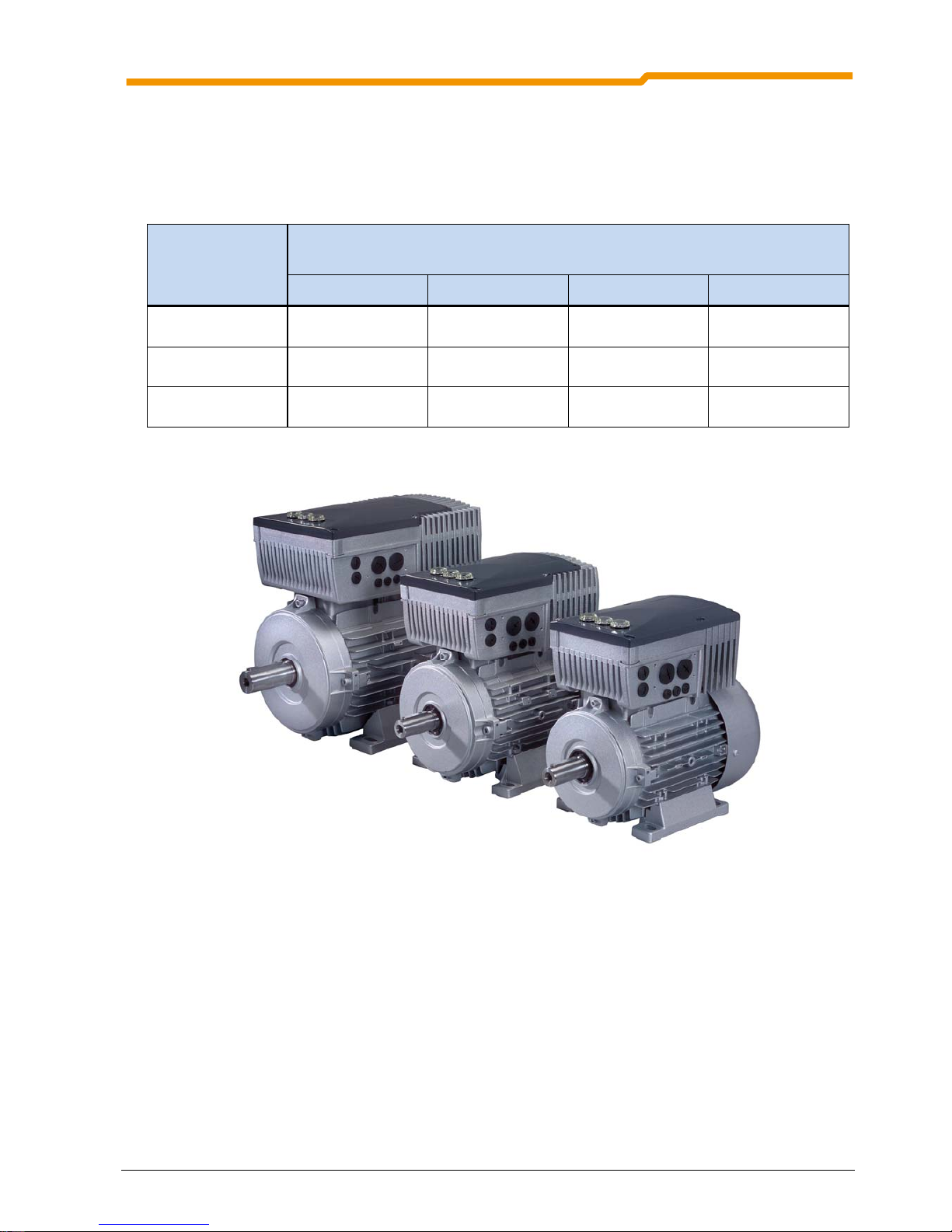
2.1 Installation and assembly
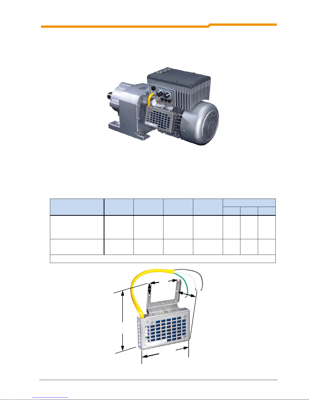
NORDAC SK 200E frequency inverters are available in various sizes depending on their output. Connection
of the SK 200E to the motor or the wall-mounting unit is made by means of the a suitable size of connection
unit SK T14-… The frequency inverter is mounted by means of integrated plug contacts.
The devices require adequate ventilation to protect against overheating. For further details, please refer to
Section 7 “Technical Data”.
Motor-mounted version
: Here, the ventilation of the motor is integrated into the cooling concept of the FI.
Mounting must therefore always be carried out as shown in the illustration. For permanently low motor
speeds and self-ventilated motors, a reduction in power similar to the wall-mounted version must be taken
into account.
Wall-mounted version
: In continuous operation (S1), mounting away from the motor causes a reduction in
the power of the FI by one power level. This means that relative to the motor, the FU must be selected one
power level larger.
NOTE
For further details of the power reduction and the possible ambient temperatures, please
refer to the technical data in Section 7.
Page 20
NORDAC SK 200E Manual
20 Subject to technical alterations BU 0200 GB
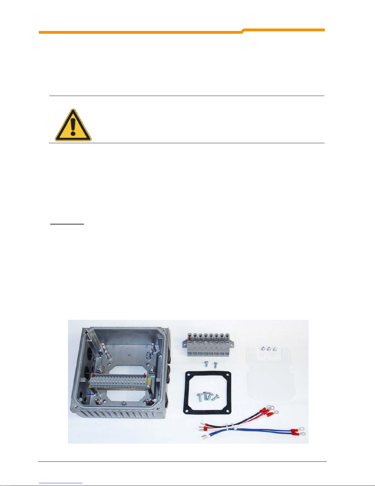
2.1.1 Mounting the adapter unit
For the supply of a complete drive unit (gear unit + motor + frequency inverter) the SK 200E frequency
inverter and the SK T14-... adapter unit are always completely assembled and tested. The adapter unit can
also be ordered separately for subsequent mounting on an existing motor or to replace a different motormounted frequency inverter.
NOTE
However, the IP66 compliant SK 200E must be mounted by NORD as special measures must
be implemented. IP66 components retrofitted on site cannot ensure that this protection class is
guaranteed.
The “Adapter unit SK T14” includes the following components:
Cast housing, seal (already glued in) and insulation plate
Power terminal block, corresponding mains connection
Control terminal block, corresponding SK 200E version
Screw kit, for mounting on the motor and the terminal bars
Pre-fabricated cable for motor and PTC connections
Procedures:
1. If necessary, remove the original terminal box from the NORD motor, so that only the base of the
terminal box and the terminal strip remain.
2. Set the bridges for the correct motor circuit and connect the pre-fabricated cables for motor and PTC
connections to the respective connection points on the motor.
3. Mount the cast housing on the terminal box base using the existing screws and seal. Position the cast
housing with the dome facing the A-side of the motor. Check the adaptability for different motor
manufacturers.
4. Attach the insulating plate above the terminal strip. Screw on the power terminal bar above this using the
2 M4x8 screws and the plastic washers.
5. Connect the motor cables U, V, W to the power terminal block and the PTC cable TF+, TF- to the control
terminal block 38, 39.
Page 21
2 Mounting and Installation
BU 0200 GB Subject to technical alterations 21
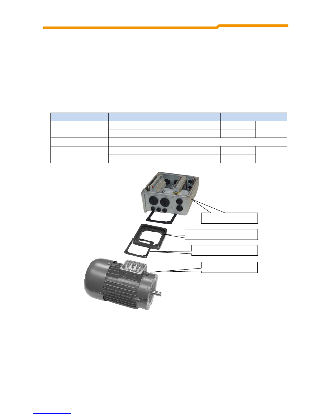
2.1.2 Adapters for Different Motors
The mounting of the terminal box differs for the different motor sizes 63 to 112. Because of this, several
mounting components are available.
In order to guarantee the maximum protection class IP55 / IP66 of the entire unit, motor must also have a
corresponding protection class.
Mounting of SK 200E S I
The adapter unit can be directly attached to size 80 - 100 NORD motors. An additional adapter plate/spacer
with an additional seal is required for the sizes 63-71 and 112.
NORD motor sizes Mounting of SK 200E S I Part. No.
Size 63 - 71
Mounting with adapter plate, size 63 – 71 011015410
Additional terminal box frame seal 013097000
Size 80 – 100 Direct attachment of adapter unit
Size 112 (e.g. 6-pin)
Mounting with spacer S 112 013035450
Kit
275115120
Additional terminal box frame seal 013097000
Adapter plate, Part No. 011015410
Seal Part No. 13097000
Motor, size 71
Connection unit SK TI4
Important! The adaptability of motors from other manufacturers must be checked individually!
Page 22
NORDAC SK 200E Manual
22 Subject to technical alterations BU 0200 GB
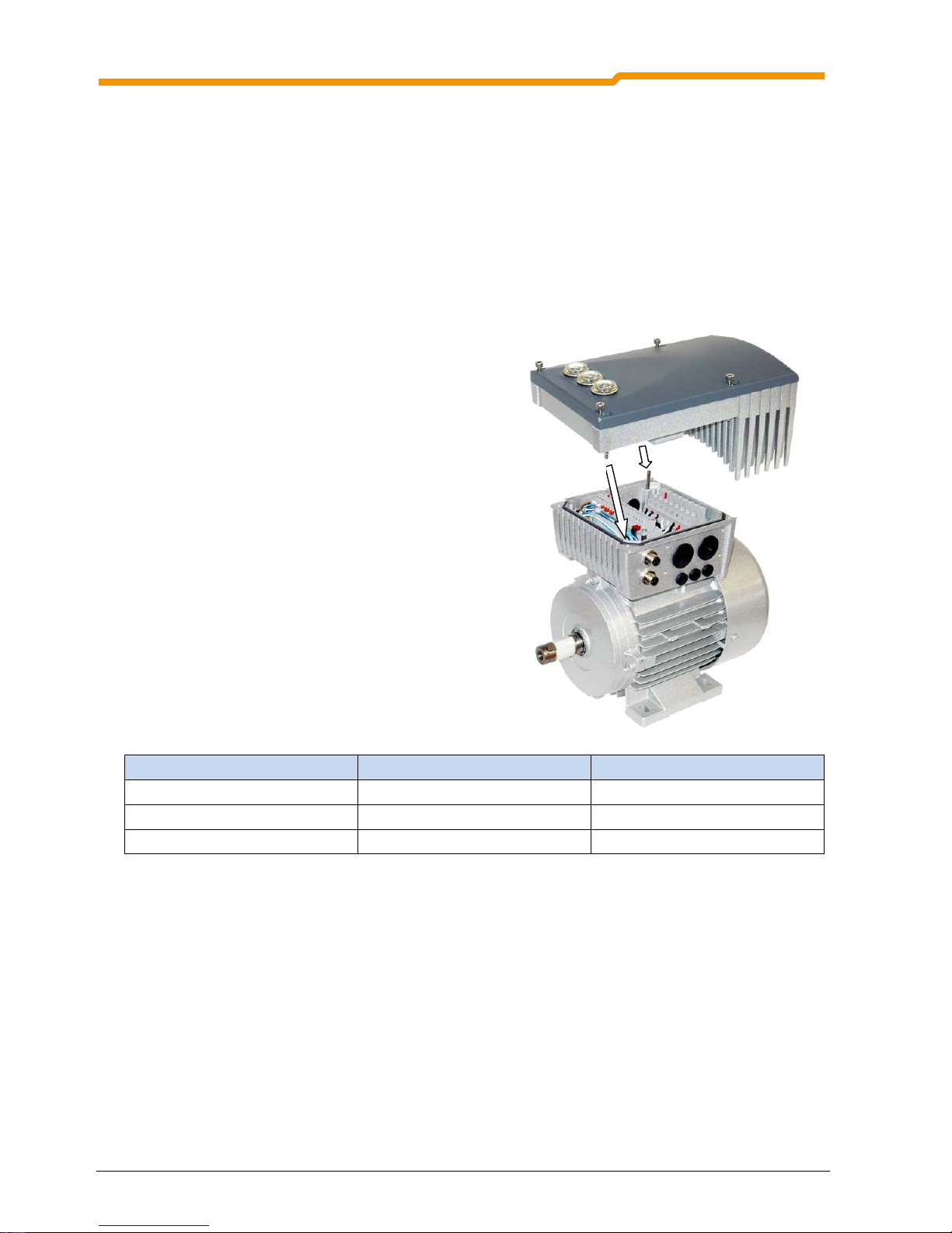
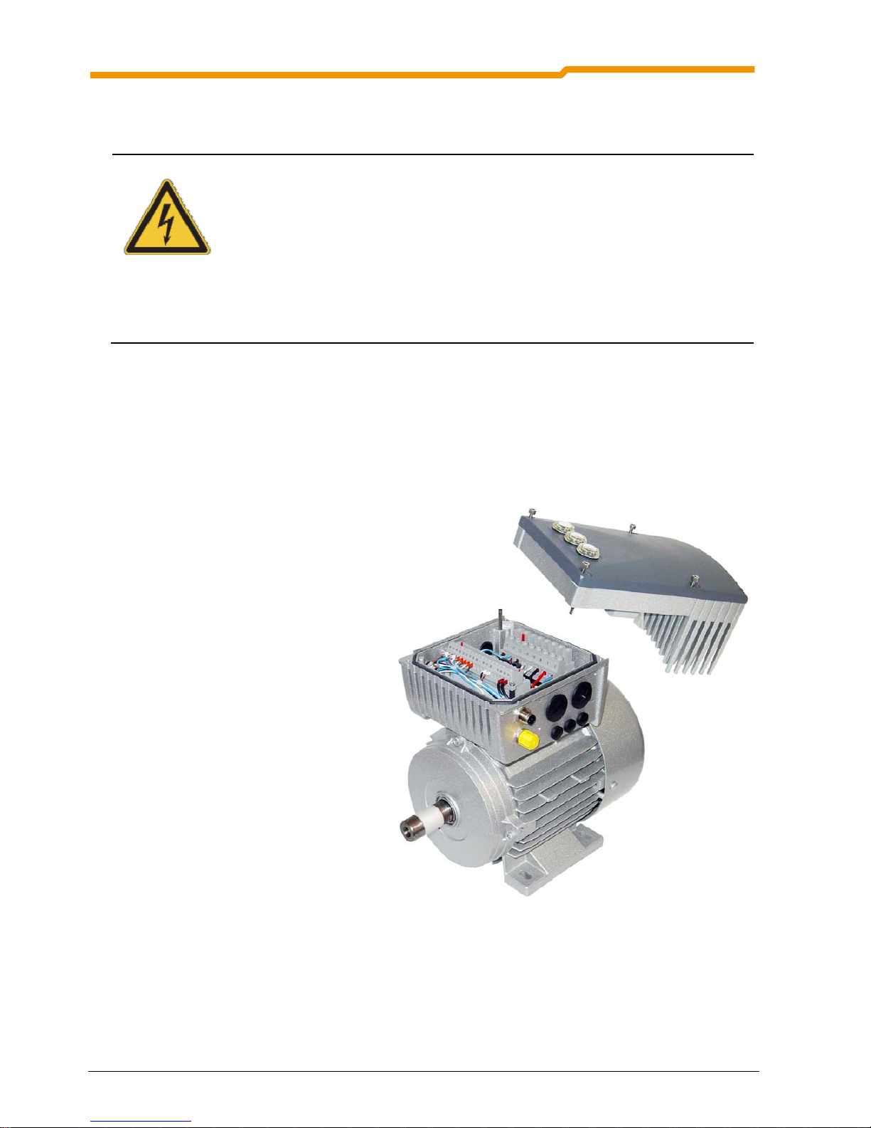
2.1.3 Installation of the SK 200E
In order to carry out the electrical connection of the SK 200E, this may need to be removed from the
connection unit. To do this, remove the 4 fastening screws, so that the frequency inverter can be lifted off
vertically.
After the electrical connection of the power cables has been made, the frequency inverter can be replaced.
This must be carried out in a vertical direction relative to the connection unit without tilting. The PE cinch
plug can be used in order to ensure correct guidance.
In order to achieve the maximum protection class
IP55/IP66, care must be taken that all frequency
inverter fixing screws are gradually tightened
diametrically oppositely, with the torques stated in
the table below.
For the cable gland of the connecting cable,
appropriate screwed connections for cable crosssection must be used.
Dissipation of heat generated by the inverter occurs
by means of convection. This is assisted by the
airflow of the motor. Because of this, a reduction in
power for unventilated motors or wall-mounted
devices must be taken into account (for further
details see Section 7, Technical Data).
Heat dissipation must not be hindered by severe
contamination.
Frequency inverter size Screw size Tightening torque
Size I M5 x 45 3.5Nm ± 20%
Size II M5 x 45 3.5Nm ± 20%
Size III M5 x 45 3.5Nm ± 20%
Cinch pl ug
Page 23
2 Mounting and Installation
BU 0200 GB Subject to technical alterations 23
2.2 Dimensions: SK 200E
2.2.1 Power rating / Motor size
Size
Mains/power matching: SK 200E
1~ 110-120V 1~ 200-240V 3~ 200-240V 3~ 380-480V
Size I
0.25 ... 0.37kW 0.25 ... 0.55kW 0.37 ... 1.1kW 0.55 ... 2.2kW
Size II
0.55 ... 0.75kW 0.75 ... 1.1kW 1.5 ... 2.2kW 3.0 ... 4.0kW
Size III
- - 3.0 ... 4.0kW 5.5 ... 7.5kW
Page 24
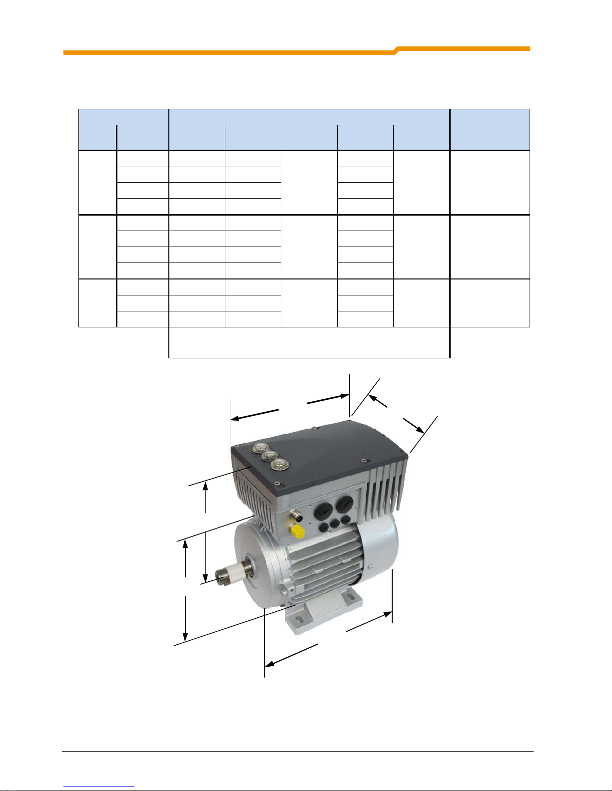
NORDAC SK 200E Manual
24 Subject to technical alterations BU 0200 GB
2.2.2 SK 200E mounted on motor
Size Housing dimensions SK 200E / Motor Weight: SK 200E
without motor
Approx. [kg]
FI
Motor
g
g 1 n o p
Size I
BG 71 * 145 201
236
214
156 3.0
S 80 165 195 236
S 90 183 200 276
S 100 201 209 306
Size II
S 80 165 202
266
236
176 4.1
S 90 183 207 276
BG100 201 218 306
S 112 228 228 326
BG III
BG100 201 251
330
306
218 6.9
S 112 228 261 326
S 132 266 262 411
All dimensions in [mm]
*) including additional adapter and seal (11015410, 13097000)
n
g 1
p
g
n
Page 25
2 Mounting and Installation
BU 0200 GB Subject to technical alterations 25
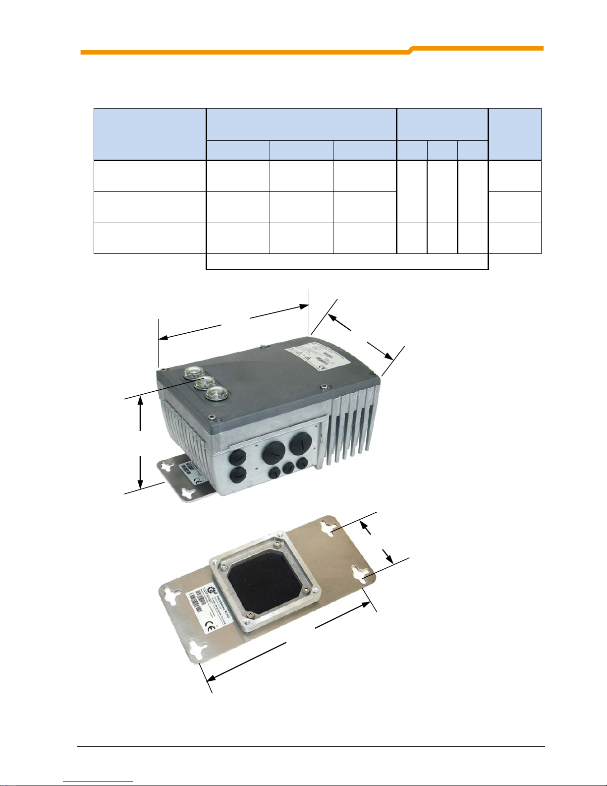
2.2.3 SK 200E Wall-mounting
Device type
Size
Housing dimensions
Wall mounting
SK TIE4-WMK-1/-2
Total weight
Approx. [kg]
g2 n p d e
Size I SK TIE4-WMK-1
Mat. No. 275 274 000
130.5 236 156
180 64 5.5
3.1
Size II SK TIE4-WMK-1
Mat. No. 275 274 000
137.5 266 176 4.2
Size III SK TIE4-WMK-2
Mat. No. 275 274 001
154.5 330 218 210.5 74 5.5 7.0
All dimensions in [mm]
n
g
2
p
d
e
SK 200 E with w all mou nting kit
SK TIE4-WMK-...
Page 26

NORDAC SK 200E Manual
26 Subject to technical alterations BU 0200 GB
2.3 Brake resistor (BR)
During dynamic braking (frequency reduction) of a three phase motor, electrical energy is returned to the
frequency inverter. In order to avoid an overvoltage switch-off of the frequency inverter, an external brake
resistor can be used. With this, the integrated brake chopper (electronic switch) pulses the intermediate
circuit voltage (switching wave approx. 420V/720V DC, according to the mains voltage) to the brake resistor.
Here the excess energy is converted into heat.
CAUTION
The braking resistance and all other metal components can heat up to temperatures above 70°C.
When mounting, sufficient distance from neighbouring components must be maintained. When
working on the components, allow sufficient cooling time beforehand
2.3.1 Internal brake resistor SK BRI4-…
The internal brake resistor can be used if only slight, short braking phases are to be expected.
NOTE
With the use of internal resistors, the DIP switch 8 must be set to “On”. This is important in
order to activate a limitation of the peak power of the brake resistor. Otherwise, the brake
resistor may be damaged during operation.
Alternatively, a suitable power limit can also be set in P555, P556 and P557. However, this
is only effective if DIP 8 is set to the “Off” position.
Page 27
2 Mounting and Installation
BU 0200 GB Subject to technical alterations 27
2.3.2 External brake resistor SK BRE4-…
The external brake resistor is intended for the feedback of energy, such as occurs in cyclical drives or lifting
equipment. Here, it may be necessary to plan for the exact brake resistor required.
For installation, an M20 screw connection with an adapter for M25 are supplied. The connecting wires for
the brake resistor are fed through this into the connection unit.
The brake resistor is attached to the side of the connection unit using 4 suitable M4 x 10 screws.
2.3.3 External brake resistor dimensions
Resistor type Size A B C
Fixing dimensions
D e
SK BRE4-1-100-100
SK BRE4-1-200-100
SK BRE4-1-400-100
Size I
150 180 60 83 32 4.3
SK BRE4-2-100-200
SK BRE4-2-200-200
Size II
255 180 60 83 32 4.3
All dimensions in mm
A
B
C
d
e
Page 28

NORDAC SK 200E Manual
28 Subject to technical alterations BU 0200 GB
2.3.4 Brake resistor, electrical data
Internal
Inverter type Resistor type Resistance
Continuous
operation /
max. limit
Energy
consumption*
Connection
cable or
terminals
Size I
BR internal (DIP 8 = on)
SK BRI4-1-100-100
Mat. No. 275272005
100
100 W / 20% 1.0 kWs
Silicon flex
2x 0.75mm
2
approx.
275mm
SK BRI4-1-200-100
Mat. No. 275272008
200
100 W / 20% 1.0 kWs
SK BRI4-1-400-100
Mat. No. 275272012
400
100 W / 20% 1.0 kWs
Size II
SK BRI4-2-100-200
Mat. No. 275991115
100
200 W / 20% 2.0 kWs
Silicon flex
2x 1.0mm
2
approx.
275mm
SK BRI4-2-200-200
Mat. No. 275272108
200
200 W / 20% 2.0 kWs
*)Maximum once within 10s
In order to prevent impermissible heating of the connection unit, the
continuous power is limited to 1/5 of the BR rated power.
External
Inverter type Resistor type Resistance
Continuous
output / max.
limit
Energy
consumption*
Connecting
cable or
terminals
Size I
BR external
SK BRE4-1-100-100
Part No. 275273005
100
100 W 1.0 kWs
FEP flex
3x 1.9mm
2
AWG 14/19
approx.
350mm
SK BRE4-1-200-100
Part No. 275273008
200
100 W 1.0 kWs
SK BRE4-1-400-100
Part No. 275273012
400
100 W 1.0 kWs
Size III
SK BRE4-2-100-200
Part No. 275273105
100
200 W 2.0 kWs
FEP flex
3x 1.9mm2
AWG 14/19
approx.
500mm
SK BRE4-2-200-200
Part No. 275273108
200
200 W 2.0 kWs
*)Maximum once within 120s
Page 29

2 Mounting and Installation
BU 0200 GB Subject to technical alterations 29
2.4 Wiring guidelines
The frequency inverter has been developed for use in an industrial environment. In this environment, high
levels of electromagnetic interference can influence the frequency inverter. In general, correct installation
ensures safe and problem-free operation. To meet the limiting values of the EMC directives, the following
instructions should be complied with.
(1) Ensure that all equipment in the control cabinet is securely earthed using short earthing cables which
have large cross-sections and are connected to a common earthing point or earthing bar. It is
especially important that all control devices connected to the frequency inverters (e.g. an automation
device) are connected to the same earthing point as the inverter itself, using a short cable with large
cross-section. Flat conductors (e.g. metal clamps) are preferable, as they have a lower impedance at
high frequencies.
(2) The bonding cable of the motor controlled by the frequency inverter should be connected directly to the
earthing terminal of the associated frequency inverter. The presence of a central earthing bar in the
control cabinet and the grouping together of all bonding conductors to this bar normally ensures safe
operation. (See also Chapter 8.3/8.4 EMC)
(3) Where possible, shielded cables should be used for control loops. The shielding at the cable end
should be carefully sealed and it must be ensured that the wires are not laid over longer distances
without shielding.
The shields of analog setpoint cables should only be earthed on one side on the frequency inverter.
(4) The control cables should be installed as far as possible from power cables, using separate cable
ducts, etc. Where cables cross, an angle of 90° should be ensured as far as possible.
(5) Ensure that the contactors and brake chokes in the cabinet are interference protected, either by RC
circuits in the case of AC contactors, or by “free-wheeling” diodes for DC contactors, for which the
interference protectors must be positioned on the contactor coils. Varistors for over-voltage
limitation are also effective. This interference suppression is particularly important when the contactors
are controlled by the relay in the frequency inverter.
(6) Use screened or armoured cable for the load connections (motor cable) and earth the
screening/armour at both ends. The earthing should be made directly to the electrically conducting
mounting plate of the control cabinet or the screening angle of the EMC Kit (Section 2.4) or the EMC
screw connector of the frequency inverter.
In addition, an EMC-compliant cabling must be ensured. (see also Section 8.3/8.4 EMC)
The safety regulations must be complied with under all circumstances when installing the
frequency inverter!
NOTE
The control cables, line cables and motor cables must be laid separately. In no case should
they be laid in the same protective pipes/installation ducts.
The test for high voltage insulations must not be used on cables which are connected to the
frequency inverter.
Page 30
NORDAC SK 200E Manual
30 Subject to technical alterations BU 0200 GB
2.5 Electrical connection
WARNING
THE DEVICES MUST BE EARTHED.
Safe operation of the devices requires that is installed and commissioned by qualified personnel
in compliance with the instructions provided in this Manual.
In particular, the general and regional installation and safety regulations for work on high voltage
systems (e.g. VDE) must be complied with as must the regulations concerning correct use of tools
and the use of personal protection equipment.
Dangerous voltages can be present at the motor connection terminals even when the inverter is
switched off. Always use insulated screwdrivers on these terminal fields.
Ensure that the input voltage source is not live before setting up or changing connections to the unit.
Make sure that the inverter and motor are specified for the correct supply voltage.
In order to access the electrical connections, the SK 200E must be removed from the SK T14 connection unit.
Proceed as follows:
1. Switch off the mains supply and if necessary check and observe the waiting period.
2. Loosen the 4 Allen screws (4mm).
3. Carefully lift the FI vertically off the connection unit.
4. The electrical connections and the option slots are now freely accessible. .
To replace the FI, proceed in the opposite sequence:
5. Here, special care must be taken that the PE pins are
correctly contacted. These are located diagonally
in 2 corners of the FI and the connection unit.
6. The FI can only be placed on
the SK T14 in one orientation.
7. Evenly tighten the Allen screws in
a cross-wise direction.
Page 31

2 Mounting and Installation
BU 0200 GB Subject to technical alterations 31
L1 / L
L2 / N
L3 / PE
X1 - PE L3 L2 L1
M
3~
X2 - PE U V W +B -B
Internal or
external braking
resistor
2.6 Electrical connection of power unit
All connection terminals are located in the connection
unit of the frequency inverter.
One terminal block is provided for the power
connections and one for the control connections.
The earthing connections (device earthing) are
located on the base in the cast housing of the
connection unit.
Before and while the device is connected, the
following must be observed:
1. Ensure that the mains supply provides the correct
voltage and is suitable for the current required
(see Section. 7 Technical Data).
2. Ensure that suitable circuit breakers with the
specified nominal current range are installed
between the voltage source and the inverter.
3. Connect the mains voltage directly to the
terminals L
1-L2
/N-L3 and the earth (according to
the device).
4. To connect the motor, three flexible wires U-V-W
should be used when mounting the motor.
5. For wall-mounting a 4-conductor shielded motor
cable (recommended) to the terminals U-V-W and
earth should be used. In this case the cable
shielding should be connected to a large area of
the metallic screw connector.
NOTE: when using specific wiring sleeves, the maximum connection cross-section can be reduced.
Screwdriver: Use a 5.5mm slot-head screwdriver to connect the power unit.
NOTE: If synchronous machines or several motors are connected in parallel to a device, the
frequency inverter must be switched over to linear voltage/frequency characteristic curves,
P211 = 0 and P212 = 0.
NOTE: The use of shielded cables is essential in order to maintain the specified radio interference
suppression level. (See also Section 8.2, EMC limit classes )
ATTENTION: This device produces high frequency interference, which may make additional suppression
measures necessary in domestic environments. (Details in Section 8.3/8.4)
Page 32

NORDAC SK 200E Manual
32 Subject to technical alterations BU 0200 GB
2.6.1 Mains connections (X1 - L1, L2, L3, EARTH)
No special safety measures are required on the mains input side of the frequency inverter. It is advisable to
use normal mains fuses (see technical data) and a main switch or circuit breaker.
115V devices may only be used with a 110…120V (L/N = L1/L2) single phase supply.
230V devices may be ordered either for single phase (...-123-, L/N = L1/L2) or three phase (...-323-,
L1/L2/L3) operation. It is essential to note the type designation!
400V devices are designed for three phase mains voltage 380...480V (L1/L2/L3).
For the exact specification, please refer to the technical data in Section 7.
Connection to the bonding is by means of screw terminals in the cast housing of the connection unit:
Note
: The use of this frequency inverter on an IT network is possible after modifications by means of
jumpers. Further details in Section 2.8.6 – 2.8.7.
Cable cross-section: 0.5 ... 6mm
2
rigid/ flexible cable
AWG 20-10
For looping of the mains voltage, up to a cable cross-section of 2x 2.5mm
2
double
wire end sleeves must be used.
Tightening torque 1.2 ... 1.5Nm
PE
Mains
Page 33

2 Mounting and Installation
BU 0200 GB Subject to technical alterations 33
2.6.2 Motor cable (X2 - U, V, W, earth)
The motor cable may have a total length of up to 100m if this is a standard cable. If a screened motor cable
is used, or if the cable is laid in a well earthed metal conduit, the total length should not exceed 20m.
Note
: Please also note Section 8.2 EMC limit
classes.
Note
: For multiple motor use the total cable length
consists of the sum of the individual cable
lengths.
Cable cross-section:
0.5 ... 6mm
2
rigid/flexible cable
0.2 ...
AWG 20-10
Tightening torque
1.2 ... 1.5Nm
2.6.3 Brake resistor connection (X2 - +B, -B)
Terminals +B/ -B are intended for the connection of a suitable braking resistor. The connection should be as
short as possible.
Note
: The large amount of heat produced by the
brake resistor must be taken into account.
Cable cross-section:
0.5 ... 6mm
2
rigid/flexible cable AWG 20-10
Tightening torque
1.2 ... 1.5Nm
PE
Motor
Page 34

NORDAC SK 200E Manual
34 Subject to technical alterations BU 0200 GB
2.6.4 Mains supply jumpers
These jumpers are used to adapt the SK 200E to various forms of mains supply (e.g. IT network). As
supplied, a star configuration earthed mains supply must be used, with an earth conductor for single phase
devices.
To adapt the SK 200E to an IT network, the capacitors C
y
must be disconnected from earth. This is carried
out by changing a jumper position as shown in the diagram.
Here it must be noted that the specified degree of radio interference suppression changes. Further details
can be found in Section 8.1. EMC.
2.6.5 Jumper Circuit Diagram
As supplied, the jumpers are set in the “normal position”. With this, the mains filter has its normal effect and
results in a higher leakage current.
Cx
Cx
Cx
Cy Cy Cy
L1
L2/N
3
~
=
L
~
=
M
Jumper A
Cyzk
Cyzk
Jumper
B
Page 35

2 Mounting and Installation
BU 0200 GB Subject to technical alterations 35
Page 36

NORDAC SK 200E Manual
36 Subject to technical alterations BU 0200 GB
2.7 Electrical connection of SK 200E control unit
The control terminals are located on the inside of the frequency inverter connection unit. The connections
differ according to the version (SK 205E, 215E, 225E, 235E).
Connection terminals: Screw terminals, 3.5 mm slot-head screwdriver
Cable cross-section: 0.2 ... 2.5mm
2
, AWG 24-14, rigid or flexible, without wire end sleeves
Tightening torque 0.5 ... 0.6Nm
Control cable: Lay and shield separately from the mains/motor cables
Control voltages,
External 18…30V, min. 200mA, the current load is increased according to the equipment.
For the supply of the FI control unit and the connected options.
NOTE
GND is a common reference potential for analogue and digital inputs.
The labelling of the control terminal bar differs according to the SK 200E version.
Page 37

2 Mounting and Installation
BU 0200 GB Subject to technical alterations 37
2.7.1 Control terminals, SK 2x5E versions
LABELLING, FUNCTION
SH: "Safe stop" function
AS: Integrated AS interface
24V: External 24V power supply
GND: Reference potential for digital signals
DIN: Digital input
DO: Digital output
24V SH: "Safe stop" input
GND SH: "Safe stop" reference potential
SYS+/-: System bus
MB+/-: Electromagnetic brake control
(105V, 180V, 205V)
TF+/-: Motor PTC connection
CONNECTIONS AND FUNCTIONS FOR SK 200E VERSIONS
FI type
SK 205E SK 215E (SH) SK 225E (ASI) SK 235E (SH + ASI)
Pin
Labelling
1
44
24V, external 24V FI supply
2
44/84
24V, external 24V FI supply AS+, AS- Interface
3
40
GND, reference potential for digital signals
4
40/85
GND AS- Interface
5
21
DIN1, digital input 1
6
22
DIN2, digital input 2
7
23
DIN3, digital input 3
8
24/89
DIN4,
digital input 4
24V SH,
“Safe stop”
DIN4,
digital input 4
24V SH,
“Safe stop”
9
40/88
GND GND SH GND GND SH
10
1
DO 1, digital output 1
11
40
GND
12
77
SYS+, system bus
13
78
SYS-, system bus
14
-
---
15
79
MB+, electromagnetic brake control
16
80
MB-, electromagnetic brake control
17
38
TF+, motor PTC connection
18
39
TF-, motor PTC connection
Page 38

NORDAC SK 200E Manual
38 Subject to technical alterations BU 0200 GB
2.7.2 Details of the SK 2x5E control connections
Control voltage 24V external! Terminal 44. If the frequency inverter does not have an optional internal mains
unit, it must be provided with an external 24V supply.
Terminal/
Name
Function
[factory setting]
Data Description / wiring suggestion Parameter
SK 205E, SK 215E, SK 225E, SK 235E
44 24V external 24V supply
18VDC ... 30VDC -/+0%
200mA ... 800mA
according to the FI load,
the inputs and outputs and
equipment with options
External supply voltage for the FI
control unit and the DO1 output
For SK 225/235E and use of the
AS-I (yellow cable), the SK 200E is
supplied from the AS-I
-
40 GND
Reference potential
for digital signals
-
21 DIN1 digital input 1
[ON right]
Digital input as per EN
61131-2, Type 1
low: 0-5V (~ 9.5kΩ)
high: 15-30V
(~ 2.5-3.5kΩ)
Input capacitance:
Input 1 + 4 = 10nF
Input 2 + 3 = 1.2nF
Scanning time: 1ms
Reaction time: ≥ 4ms
40
44
24
23
22
21
GND
24V
Inputs 1 + 4 react normally
Inputs 2 + 3 react quickly
P420 [01]
22 DIN2 digital input 2
[ON left]
P420 [02]
23 DIN3 digital input 3
[parameter set bit0]
P420 [03]
24 DIN4 digital input 4
[fixed frequency 1,
P429]
P420 [04]
1 DO1 Output 1
[no function]
digital output
18-30V, each to VI 24V
max. 200mA
max. 100k load
For evaluation in a control system.
With SK 225/235E and the use of
the AS-I (yellow cable), DO1 must
not be loaded, as the load on As-I
may be too high.
P434
38 TF+ PTC resistor input
-
For monitoring the motor
temperature by PTC.
For separate mounting of the motor
and the FI (cable length), shielded
cable must be used.
-
39 TF- PTC resistor input
77 SYS+ System bus
Up to four SK 200E can
be operated on a system
bus.
Address = 32 / 34 / 36 / 38
Internal FI system bus for
communication with optional
modules and other frequency
inverters.
Further details in Bus Manual BU
0250.
P509/510
P514/515
78 SYS-
System bus
Page 39

2 Mounting and Installation
BU 0200 GB Subject to technical alterations 39
Terminal/
Name
Function
[factory setting]
Data Description / wiring suggestion Parameter
79 MB+ Brake control
Voltage:
Mains Brake
115 / 230V 105V=
400V~ 180V=
460/480V~ 205V=
Current: max. 0.5A
To control an electro-mechanical
brake, the frequency inverter
generates an output voltage at the
terminals MB+/MB-. This depends
on the supply voltage to the SK
200E.
It is essential to take the correct
brake coil voltage into account in
the selection.
(NOTE: this function is identical to
P434=1)
P107,
P114,
P505
80 MB-
Brake control
Additionally for SK 215E and SK 235E
89 24V SH
24V input for the
“Safe stop" function
18…30V
at least 120-150mA
Fail-safe input
-
88 GND SH
Reference potential
for the “Safe stop"
function
0V digital
Reference potential
Additionally for SK 225E and SK 235E
84 AS+
Actuator/ Sensor
Interface
Simple setting by means
of DIP switch 4 and 5 on
the SK 200E
For the control of the SK 200E via
the simple field bus level.
Here, only the yellow AS interface
cable can be used. An additional
feed via the black cable is not
possible.
P480
... P483
85 AS-
M12 optional
AS interface data
Supply of AS interface
connection,
PWR connection
(yellow cable)
26.5 – 31.6V, max. 290mA
Connector PWR M12
1 AS-I (+)
2 AUX GND
3 AS-I (-)
4 AUX 24V
5 n.c.
Slave profile S-7.0
I/O-Code 7
ID Code 0
Ext. ID-Code 1 / 2 F
Address 01 – 31 (Condition as delivered: 0)
Page 40

NORDAC SK 200E Manual
40 Subject to technical alterations BU 0200 GB
Terminal/
Name
Function
[factory setting]
Data Description / wiring suggestion Parameter
All SK 200E, RJ12, RS485/RS232 connector block
1 RS485 A
Data cable RS485
Baud rate
9600…38400Baud
The termination resistor
R=120 must be installed
on the final participant by
the customer.
RS485_A
RS485_B
GND
TXD
RXD
+5V
+24V
RJ12: Pin No. 1 … 6
1: RS485_A
2: RS485_B
3: GND
4: RS232_TxD
5: RS232_RxD
6: +24V
P502
...P513
2 RS485 B
3 GND
Reference potential
for Bus signals
0V digital
4 RS 232 TXD
Data cable RS232
Baud rate
9600…38400Baud
5 RS 232 RXD
6 +24V
24V supply voltage
from the FI
24V 20%
All SK 200E, cable accessories
optional
Adapter cable
RJ12 to SUB-D9
... for direct
connection to a PC
with NORD CON
software
Length 3m
RS 232 connections
(RxD, TxD, GND)
Part No. 278910240
TxD
RxT
GND
+24V
n.c.
n.c.
Pin2: RS232_TxD
Pin3: RS232_RxD
Pin5: GND
RxD
GND TxD
6
1 5
9
Page 41

3 Displays and Control
BU 0200 GB Subject to technical alterations 41
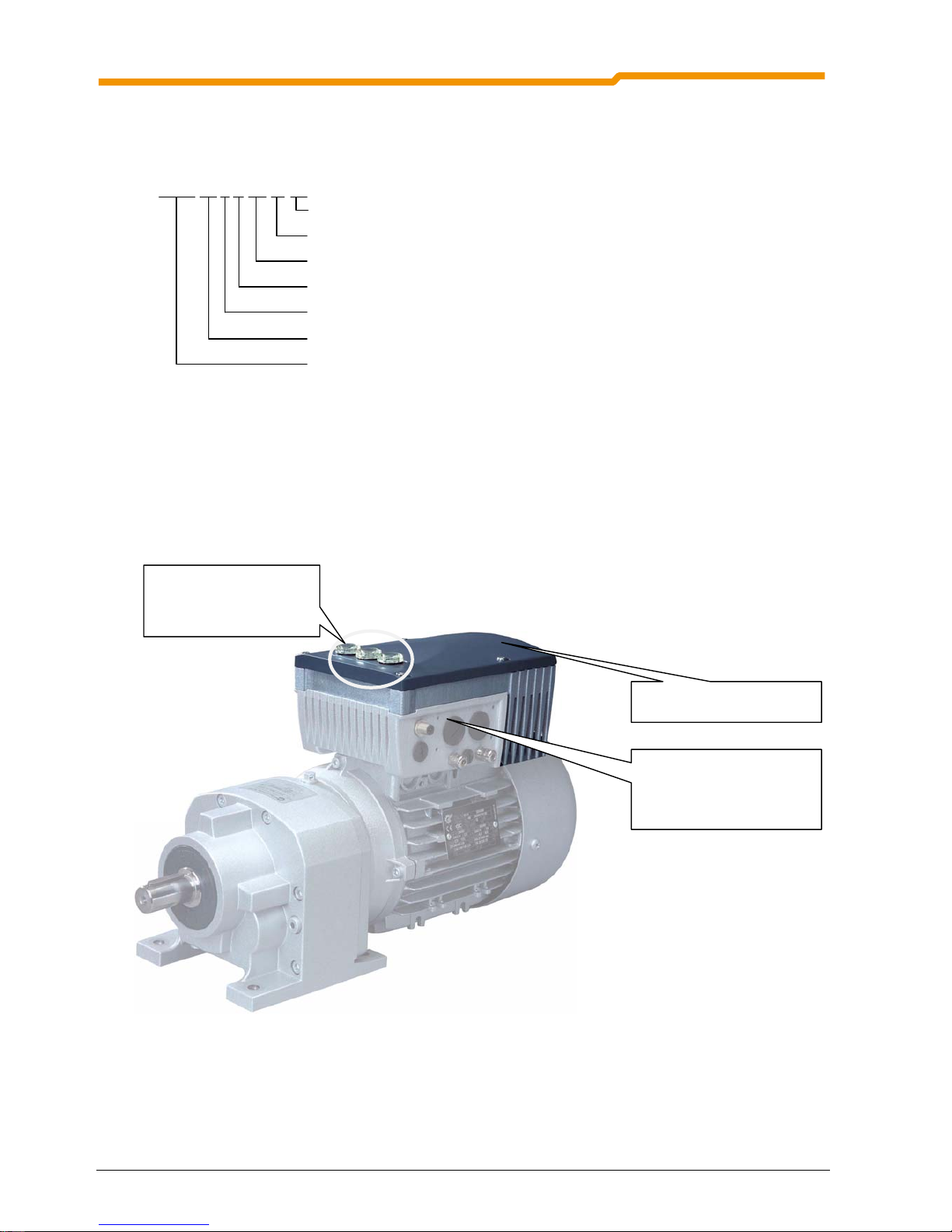
3 SK 200E displays and control
As supplied, without additional options, the diagnostic LEDs are externally visible. These signal the actual
device status. 2 potentiometers and 8 DIP switches are provided in order to set the most important
parameters. In this minimal configuration no other adapted parameters are stored in the plug-in EEPROM.
The only exception is the data concerning operating hours, faults and fault circumstances. This data can be
stored in the EEPROM.
SK200Emountedonmotor,topview SK200Enotfitted,viewfrominside
RJ12
LEDs
Potentiometers
Plug-in EEPROM
8x DIP switches
All parameters can be conveniently accessed for reading or setting with the aid of an optional SimpleBox or
ParameterBox (Section 3.2). The changed parameter data is stored in a non-volatile EEPROM memory.
This provides the possibility of transferring data from one FI to another by plugging in the EEPROM.
In addition, up to 5 complete frequency inverter data sets can be stored and accessed in the ParameterBox.
Connection between the SimpleBox or ParameterBox is by means of an RJ12-RJ12 cable.
Page 42

NORDAC SK 200E Manual
42 Subject to technical alterations BU 0200 GB
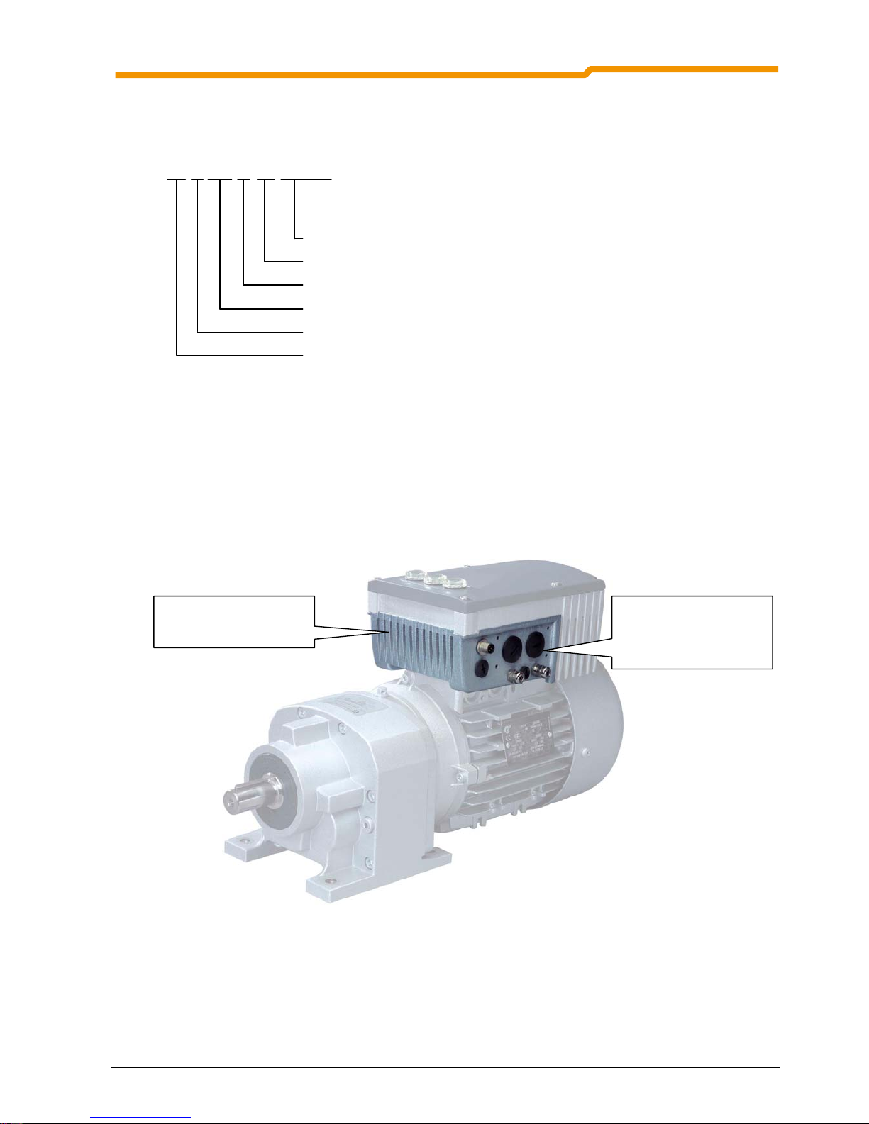
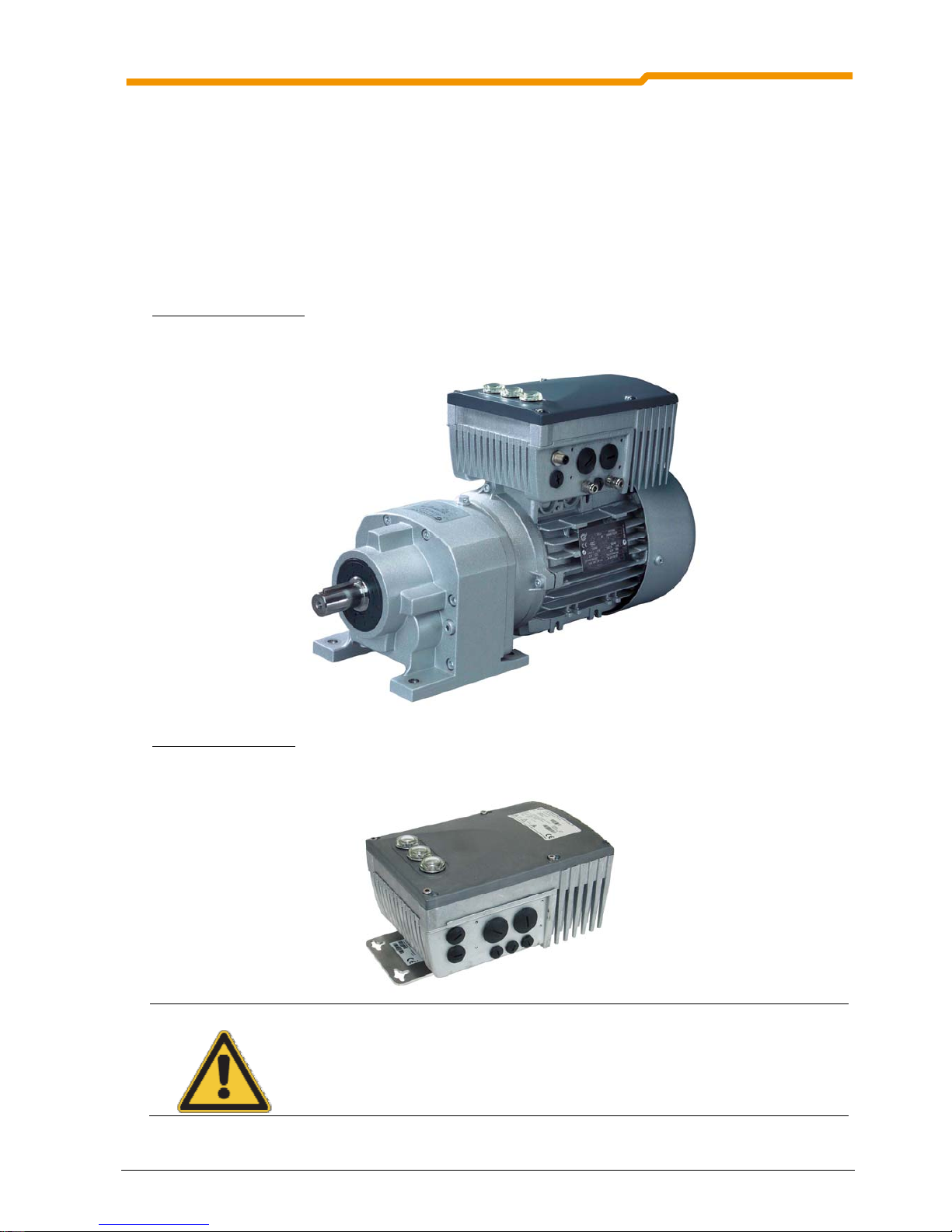
3.1 SK 200E modular components
By combining different modules for display, control and parameterisation, the NORDAC SK 200E can be
easily adapted to various requirements.
Alphanumerical display and operating modules can be used for simple commissioning (Section 3.2). For
more complex tasks, various connections to a PC or an automation system can be selected.
The Customer Unit (SK CU4-…) is integrated into the SK 200E. The electrical connection to the SK 200E is
made via the internal system bus. This is equipped with screw terminals for connection to external peripherals.
As an option, we also provide the possibility of using 4/5-pin M12 plug connectors in the FI housing.
The technology unit (Technology Unit, SK TU4-…) is externally attached to the frequency inverter and is
therefore easy to access. The electrical connection to the SK 200E is made via the internal system bus.
External 4/5-pin plug connectors are available for use by the customer.
SKTI4‐...withintegratedSKCU4‐... SK200EwithexternalSKTU4‐...
WARNING
Modules must not be inserted or removed unless the device is free of voltage.
For further detailed information, please refer to the Options Manual.
-
www.nord.com -
Page 43

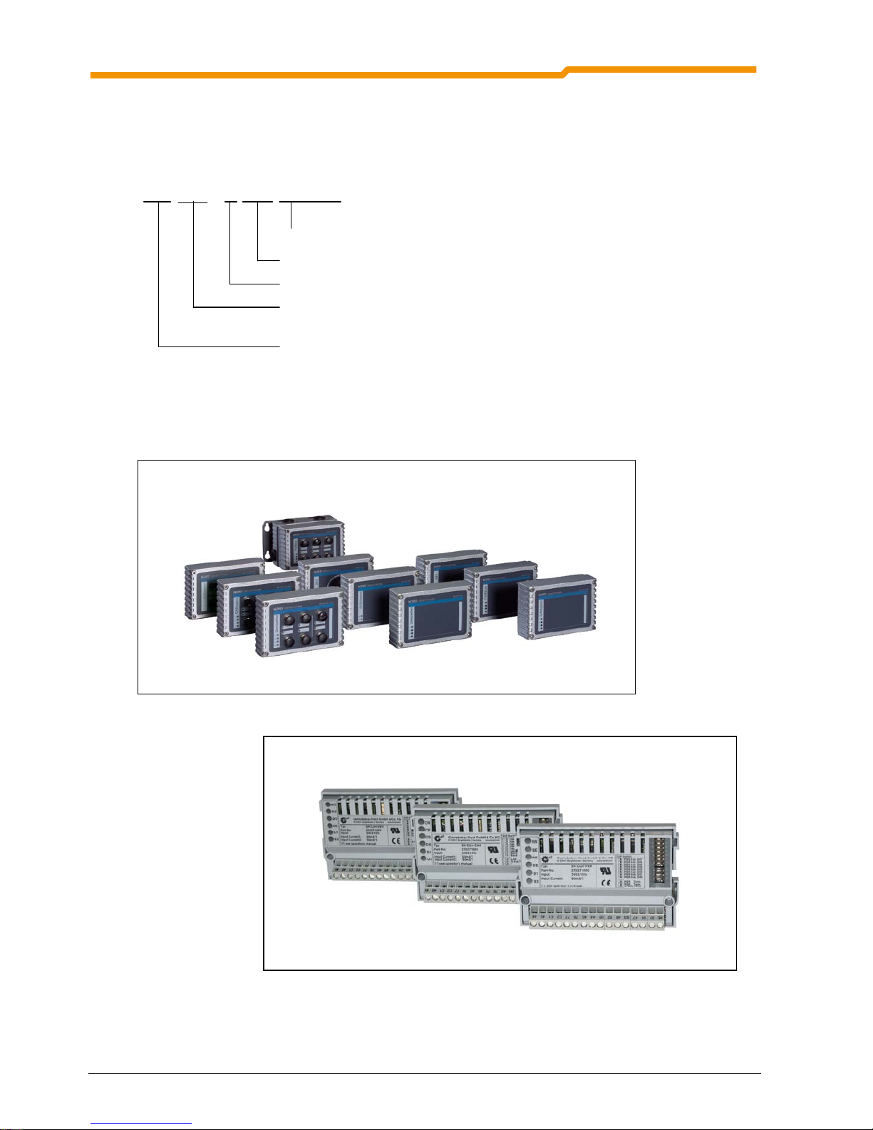
3.2 External Control Unit
BU 0200 GB Subject to technical alterations 43
3.2 Overview of external control devices
Module Description Data
SimpleBox
handheld
SK CSX-3H
Used for commissioning, parameterisation,
configuration and control of the FI. Storage of
the parameters is not possible.
Manual BU 0040 (www.nord.com)
4-digit, 7-segment LED display
IP20
RJ12-RJ12 cable
Part No. 275281013
ParameterBox
handheld
SK PAR-3H
Used for commissioning, parameterisation,
configuration and control of the FI.
Manual BU 0040 (www.nord.com)
4 digit back-lit LCD display, keyboard
Stores up to 5 complete FI data sets
IP20
RJ12-RJ12 cable
USB cable
Part No. 275281014
RJ12-RJ12 cable
For direct connection of the SK 200E to one of
the two control units.
approx. 2m long
Included in the scope of delivery of CSX and
PAR
Mounting the control unit on the SK 200E:
Mounting of the control unit is performed as
follows:
1. Remove the protective cap from the RJ12
connector.
2. Connect the RJ12-RJ12 cable between
the control unit and the frequency
inverter.
3. During normal operation after
commissioning, it is essential to replace
the protective caps and pay attention to
sealing.
4. As long as one of the protective caps is
open, take care that no dirt or moisture
enters the device.
Page 44

NORDAC SK 200E Manual
44 Subject to technical alterations BU 0200 GB
3.2.1 SimpleBox, SK CSX-3H
This option is used as a simple parameterisation, display and control tool for the SK 200E frequency
inverter.
Features
4-digit, 7-segment LED display
Complete parameterisation of the frequency inverter.
Direct control of a frequency inverter
Displays the active parameter set during
parameterisation and operation and the operating
value set in P001.
After the SimpleBox has been connected and the mains switched on, horizontal lines appear in the 4-digit 7segment display. This display signals the operational readiness of the frequency inverter.
If a creep frequency value is pre-set in parameter P113, or a minimum frequency or setpoint value is pre-set
in P104, the display flashes with this initial value.
If the frequency inverter is enabled, the display changes automatically to the operating value selected in
parameter >Selection Display value< P001 (factory setting = current frequency).
The actual parameter set in use is shown by the 2 LEDs next to the display on the left in binary code.
NOTE
The digital frequency setpoint is factory set to 0Hz. To check whether the motor is working, a
frequency setpoint must be entered with the / key or a jog frequency via the
respective parameter >Jog frequency< (P113).
Settings should only be implemented by qualified personnel, strictly in accordance with the
warning and safety information.
ATTENTION: The motor may start immediately after pressing the START key
!
Page 45

3.2 External Control Unit
BU 0200 GB Subject to technical alterations 45
Functions of the SimpleBox:
Starting the frequency inverter. The frequency inverter is now enabled with the set jog frequency
(P113). A preset minimum frequency (P104) may at least be provided. Parameter >Interface< P509
and P510 must = 0.
Stopping the frequency inverter. The output frequency is reduced to the absolute minimum
frequency (P505) and the frequency inverter shuts down.
7-segment
LED display
4-digit
4 permanently displayed underscores (_ _ _ _) indicate readiness for operation if there is no
setpoint. If these underscores are flashing, the frequency inverter is not ready for operation (switchon lock, e.g. function “safe pulse block”), or there is, or was, an error. This must first be rectified.
When the frequency inverter is ready for operation any initial value (P104/P113 for keyboard
operation) is indicated by a flashing display. This frequency is immediately displayed on being
enabled.
During operation, the currently set operating value (selection in P001) or an error code (Section 6) is
displayed.
During parameterisation, the parameter numbers or the parameter values are shown.
LEDs
1
2
The LEDs indicate the actual operating parameter set in the operating display (P000) and the actual
parameter set being parameterised during parameterisation. In this case the display is coded in
binary form.
1
2
= P1
2
1
= P2
1
2
= P3
2
1
= P4
The motor rotation direction changes when this key is pressed. "Rotation to the left" is indicated by a
minus sign.
Attention! Take care when operating pumps. screw conveyors, ventilators, etc. Block
the key with parameter P540.
Press key to increase the frequency. During parameterisation, the parameter number or parameter
value is increased
Press the key to reduce the frequency. During parameterisation, the parameter number or
parameter value is reduced.
OK
Press the “OK” key to store an altered parameter value, or to switch between parameter numbers or
parameter values.
NOTE: If a changed value is not
to be stored, the key can be used to exit the parameter
without storing the change.
Page 46

NORDAC SK 200E Manual
46 Subject to technical alterations BU 0200 GB
Control with the SimpleBox
The frequency inverter can only be controlled via the SimpleBox, if it has not
previously been enabled via
the control terminals or via a serial interface (P509 = 0 and P510 = 0).
If the START key is pressed, the frequency inverter changes to the operating display (selection P001). The
frequency inverter supplies 0Hz or a higher minimum frequency (P104) or jog frequency (P113) which has
been set.
STOP
Store curren t frequency
as jog freque nc y
Set frequ en cy = 0Hz
(pre ss simultaneously)
Increase freq uen cy
Chan ge rotation directio n
Dec re ase frequency
START
Parameter set display
Quick stop
(press simultaneously)
Parameter set display:
The LEDs indicate the actual operating parameter set in the operating display (P000) and the current
parameter set being parameterised (
P000). There, the display appears in binary form.
The parameter set can also be changed during operation via the parameter P100, if control is by means of
the SimpleBox.
Frequency setpoint:
The current frequency setpoint depends on the setting in the parameters jog frequency (P113) and minimum
frequency (P104). This value can be altered during keyboard operation with the value keys
and
permanently stored in P113 as the jog frequency by pressing the OK key
OK
.
Quick stop:
A quick stop can be triggered by simultaneously pressing the STOP key and the "Change direction key” .
Page 47

3.2 External Control Unit
BU 0200 GB Subject to technical alterations 47
Parameterisation with the SimpleBox
The
parameterisation of the FI can be performed in various operating states. All parameters can always be
changed online. Switching to the parameter mode occurs in different ways depending upon the operating
states and the enabling source.
1. If there is no
enable (if necessary, press the STOP key ) it is possible to switch to the
parameterisation mode directly from the operating value display with the value keys
or .
P 0 _ _ / P 7 _ _
2. If an enable is present via the control terminals or a serial interface and the frequency inverter is
produces an output frequency, it is also possible to switch to the parameterisation mode directly
from the operating value display using the value keys
. P 0 _ _ / P 7 _ _
3. If the FI has been enabled via the SimpleBox (START key ), the parameterisation mode can be
accessed by pressing the START and ENTER keys (
+ OK) simultaneously.
4. Switching back to the control mode is achieved by pressing the START key
.
Retu rn to operating value
display
Save currently changed
parameter value
One level back each time
until the operating value
dis
play
is reache d
Next men u gro up o r
parameter value
Exit setting without saving
Previou s men u gr oup or
parameter value
Switchover from parame-
ter isa ti o n to con tr ol
Parameter set display
Switch from control
to parameterisation
Changing parameter values
To access the parameter section, one of the value keys,
or must be pressed. The display changes to
the menu group display
P 0 _ _ ... P 7 _ _. After pressing the OK key
OK
access to the menu group is
obtained and the required parameter can be selected with the value keys.
All parameters are arranged in order in the individual menu groups in a continuous scroll pattern. It is
therefore possible to scroll forwards and backwards within this section.
Each parameter has a parameter number
P x x x . The significance and description of the parameters
starts in Section 5 "Parameterisation"
NOTE: Some parameters (e.g. P502) have additional levels (Arrays) , in which further settings can be
made, e.g.:
P01
P50 2
P02
off
of f
Setting:
Value of master function 1
Setting:
Value of master function 2
ENTER
ENTER
ENTER
V
ALUE
Page 48

NORDAC SK 200E Manual
48 Subject to technical alterations BU 0200 GB
Menu structure with the SimpleBox
P0--
_ _ _ _
P1--
P2 - -
P4--
P5- -
P6--
P7- -
P001
P002
P100
P10 1
P114
P2 00
P20 1
P220
P40 0
P4 0 1
P48 3
Operating value display
(or opera tional)
following m ains O N
P3- -
P30 0
P30 1
P32 7
P0 0 3
To
change a parameter value, the OK key
OK
must be pressed when the relevant parameter number is
displayed.
Changes can then be made using the VALUE keys
or and must be confirmed with OK to save them
in the EEPROM and exit from the parameter.
As long as a changed value has not been confirmed by pressing OK, the value has not yet been stored in
the frequency inverter.
During parameter changes, the display does not flash, so that the display is more legible.
If a change is not
to be saved, the "DIRECTION" key can be pressed to exit from the parameter.
Ret urn to operating value
display
Save
changed value
Call up the default se ttings
for the parame ter value
Increase parameter value
Do n ot sa ve
chan ge d va lue
Reduce parameter value
Page 49

3.2 External Control Unit
BU 0200 GB Subject to technical alterations 49
3.2.2 ParameterBox, SK PAR-3H
This option is for simple parameterisation and control of the frequency inverter, as well as the display of
current operating settings and states.
Up to 5 data sets can be stored and managed, stored and transferred with this device. This enables an
efficient start-up for serial applications.
NOTE: In order to use the ParameterBox SK PAR-3H with the SK 200E, this must at least have
software 4.0 R3 installed.
Features of the ParameterBox
Illuminated, high resolution LCD graphics screen
Large-screen display of individual operating parameters
6 language display
Help text for error diagnosis
5 complete inverter data sets can be stored in the
memory, loaded and processed
Can be used for the simultaneous display of several
operating values
Standardisation of individual operating parameters to display specific system data
Direct control of a frequency inverter
Information from the ParameterBox
After plugging the ParameterBox onto the frequency inverter and switching on the mains for the first time,
there is initially an
enquiry as the menu language, German or English. The required language is
confirmed by pressing OK.
Then the ParameterBox automatically carried out a “bus scan”, during which the connected frequency
inverters are identified.
In the following display, the type of frequency inverter, its actual operating condition and the current status
can be seen.
After the inverter has been enabled, the display mode changes to the 3 current operate values (frequency,
voltage, current). The operating values displayed can be selected from a list of possible values (in the
>Display< / > Values< menu).
NOTE
The digital frequency setpoint (Jog frequency/minimum frequency) has a default setting of 0Hz.
To check whether the motor is working, a frequency setpoint must be entered with the
key or a jog frequency entered via the relevant menu level >Parameterise<, >Base
parameters< and the relevant parameter >Jog frequency< (P113).
Settings should only be made by qualified personnel, in strict compliance with the warning
and safety information.
ATTENTION: The motor may start immediately after pressing the START key !
Page 50

NORDAC SK 200E Manual
50 Subject to technical alterations BU 0200 GB
Functions of the ParameterBox
LCD
Display
Graphic-capable, backlit LCD display for displaying operational values and parameters for the
connected frequency inverter and ParameterBox parameters.
Using the SELECTION
keys enables toggling between the menu levels and menu items.
Press the
and keys together to go back one level.
The contents of individual parameters can be altered with the
VALUES keys.
Press the
and keys together to load the default values of the parameter selected.
When controlling the inverter using the keyboard, the frequency setpoint is set using the VALUE keys.
Here the ramp time is limited to 0.17s/Hz, even if small values are set in P002/P003.
OK
Press the
OK key to change to the selected menu group or accept the changed menu items or
parameter values.
NOTE: If a parameter is to be exited, without a new value being stored, then one of the
SELECTION keys can be used for this purpose.
If the inverter is currently controlled from the keyboard (not control terminals), then the current actual
frequency can be stored under the Jog Frequency parameter P113 with the OK key and used as the
next initial setpoint frequency.
START key for switching on the frequency inverter.
NOTE:
These functions can
only be used of they
are enabled in
parameter P509 or
P540.
STOP key for switching off the frequency inverter.
The direction of rotation of the motor changes when the
DIRECTION key is
operated. Rotation direction left is indicated by a minus sign.
Attention! Take care when operating pumps, screw conveyors, ventilators, etc.
LEDs
DS
DE
The LED's indicate the actual status of the ParameterBox.
DS – Device State The ParameterBox is ready for operation.
DE – Device Error An error has occurred when processing data, or in the FI.
LCD display
205E 1.1kW / 400V 1
Fi/Hz U/V I/A
45.0 360
2.4
ONLINE FI P1 R R U NN ING
Frequency inverter type
Conn ec tio n to frequency
inverter
Frequency inverter status
Frequency inverter
power , voltage
Cur ren t operating values
Frequency, voltage,
current
Operating parameter set
Page 51

3.2 External Control Unit
BU 0200 GB Subject to technical alterations 51
Menu structure
The menu structure consists of various levels, which are each arranged in a ring structure. The OK key
moves the menu on to the next level. Pressing the SELECTION keys simultaneously moves the menu back
one level.
Parameter 1
management
P1201 2
Copy - Source
P1202 2
Copy - Target
P1204 2
Load default values
P1203 2
Copy - Sta rt
P1205 2
Delete memory
P0 2
Back
Parameterisation 1
Display 1
P1001 2
Bus scan
P100 2 2
FI selection
P1004 2
Values for display
P1003 2
Display mod e
P1005 2
Standa rd isation factor
P0 2
Back
Option s 1
P13 0 1 2
Langua ge
P13 0 2 2
Operating mode
P13 0 4 2
Contrast
P13 0 3 2
Auto m atic bus scan
P13 0 5 2
Set pa ss w ord
P13 0 6 2
Box p a ssw o rd
P0
zu rüc k
205E 1.1k W / 40 0V 1
Fi/Hz U/V I/A
45.0 360 2.4
ONLINE FI P1 R RUNNING
U1 U2 U3 U4 U5
1 - - - -
OK - - - -
90
P1 30 7 2
Re se t bo x pa ram ete r
P0 2
Back
P0
zurück
P13 0 8 2
NOR DAC p-box
Version 4.0 R1
Basic paramete rs 2
>OK< (to l evel 3)
P0 2
Back
Frequency inverter
menu structure
S ect ion 5
Parame terisation
Motor data 2
>OK< (to level 3)
O perating d isplays 2
>OK< (to le vel 3 )
P1101 2
Object selection
>Display< (P11xx), >Administer Parameters< (P12xx) and >Options< (P13xx) are purely ParameterBoxparameters and do not have direct influence on frequency inverter parameters.
Via the menu >Parameterisation< the frequency inverter structure can be accessed, if necessary after
selection of the object, if frequency inverter data sets are already stored in the ParameterBox.
The description of the frequency inverter parameters is in Section 5 of this description.
Page 52

NORDAC SK 200E Manual
52 Subject to technical alterations BU 0200 GB
Select language, short description
The following steps must be carried out to change the menu language used in the ParameterBox display.
On switching on the ParameterBox for the first time, “German” or “English” will be offered for selection. The
selection is made by pressing the selection keys (arrow R/L) and confirming with the OK key.
In the following, “English” was selected on switching on for the first time. After this selection the following
displays should appear (varies depending upon output and options).
205E 1.1kW/400V 1
> NORDAC <
Frequenzumrichter
ONLINE FI P1 E-block
Use the Selection keys or , to scroll
to the
Options menu
1
Optionen
>OK<
ONLINE FI P1 E-block
P1301 2
Sprache
Deutsch ...
ONLINE FI P1 E-block
Then press >OK<
OK
Using the Value key , select the required
language
... English
... Français
... Espanol
... Sverige
... Nederlands
After selection confirm with >OK<
OK
P1301 2
Language
English (e.g.)
ONLINE FI P1 Locked
Press both Selection keys and ,
simultaneously
1
Options
>OK<
ONLINE FI P1 Locked
205E 1.1kW/400V 1
> NORDAC <
Frequency Inverter
ONLINE FI P1 Locked
Press both Selection keys and ,
simultaneously
Initial display
Page 53

3.2 External Control Unit
BU 0200 GB Subject to technical alterations 53
Controlling the frequency inverter with the ParameterBox
The frequency inverter can only be completely controlled via the ParameterBox if the parameter >Interface<
(P509) is set to the >Control terminal or Keyboard< function (=0) (factory setting) and the inverter is not
enabled via the control terminal.
STO P
Store current frequency
as jog fre que nc y
Press simultaneously:
Set frequ en cy = 0Hz
Increase freq uen cy
Chang e rot ation direction
Decr ease frequency
START
Note: If the frequency inverter is enabled in this mode, then the parameter set is used, which is
selected for this frequency inverter in the Menu >Parameterisation< ... >Basic parameters< ...
under Parameters >Parameter set<.
Attention: Following the START command, the frequency inverter may start up immediately with a pre-
programmed frequency (minimum frequency P104 or jog frequency P113).
Parameterisation with the ParameterBox
The parameterising mode is entered by selecting the group >Parameterisation< in menu level 1 of the
ParameterBox and confirming this with the OK key. The parameter level of the connected frequency inverter
is now visible.
Press simultaneously:
default settings fo r this
parameter
Increase parameter value
Redu ce p ar ameter valu e
Open m enu g rou p or
sav e new setting
Press simultaneously:
one level b ack
Increase menu group
or parameter
Redu ce menu group
or parameter
Page 54

NORDAC SK 200E Manual
54 Subject to technical alterations BU 0200 GB
Menu structure level
Screen layout during parameterisation
If the setting of a parameter is changed, then the value flashes until it is confirmed with the OK key. In order
to retain the default settings for the parameter being edited, both VALUE keys must be pressed
simultaneously. Even in this case, the setting must be confirmed with the OK key in order for the change to
be saved.
If the change is not to be saved, then pressing one of the SELECTION keys will call up the previously stored
value and pressing a SELECTION key again will exit the parameter.
P102 PS1
3
Acceleration time
2.90 s
ONLINE FI
P1
E ready
NOTE: The lowest line in the display is used to display the current status of the box and the frequency
inverter being controlled.
NOTE:
Some parameters (e.g. P502) have additional array levels, in which further settings can be
made. The required array level must first be selected (see parameterisation, Section 5) and
confirmed with OK. The required parameter setting can now be made.
P502 PS1 [01]
3
Master function value
Off
ONLINE FI
P1
E ready
Parameter set to be edited
Parameter to be edited (No.)
Parameter to be
edited (text)
Current parameter
value
Current
ParameterBox
status
Selected
control medium
Active parameter set in
control object
Status of control object
Array level of
selected parameter,
e.g. [01], [02], [03]...
Page 55

3.2 External Control Unit
BU 0200 GB Subject to technical alterations 55
3.2.3 ParameterBox parameters
The following main functions are assigned to the menu groups:
Menu group No. Master function
Display (P10xx):
Selection of operating values and display layout
Parameterisation (P11xx):
Programming of the connected inverter and all storage media
Parameter administration (P12xx):
Copying and storage of complete parameter sets from storage media and
inverters
Options (P14xx):
Setting the ParameterBox functions and all automatic processes
Display
Parameter Setting value / Description / Note
P1001
Bus scan
A bus scan is initiated with this parameter. During this process a progress indicator is
shown in the display.
After a bus scan, the parameter is "Off".
Depending on the result of this process, the ParameterBox goes into the "ONLINE" or
"OFFLINE" operating mode.
P1002
FI selection
Selection of the current item to be parameterised/controlled.
The display and further operating actions refer to the item selected. In the inverter selection
list, only those devices detected during the bus scan are shown. The actual object appears
in the status line.
Value range: FI, S1 ... S5
P1003
Display mode
Selection of the operating values display for the ParameterBox
Standard: Any 3 values next to each other
List: Any 3 values listed with units
Large display: 1 value (any) with unit
P1004
Values for display
Selection of a display value for the actual value display of the ParameterBox.
The value selected is placed in the first position of an internal list for the display value and
is then also used in the Large Display mode.
Possible actual values for the display:
Actual frequency Voltage Current
Speed of rotation Torque current Desired frequency
ZK voltage Bus actual value1, non-standardised
P1005
Standardisation factor
The first value on the list displayed is scaled using the standardisation factor. If this
standardisation factor varies from a value of 1.00, then the units of the scaled value are
hidden in the display.
Value range: -327.67 to +327.67; resolution 0.01
Parameterisation
Parameter Setting value / Description / Note
P1101
Object selection
Selection of the object to be parameterised.
The ongoing parameterisation process relates to the object selected. Only the devices and
storage objects detected during the bus scan are displayed in the selection list. If only one
frequency inverter is connected and no storage address occupied, this parameter is not
displayed!
Value range: FI, S1 ... S5
Page 56

NORDAC SK 200E Manual
56 Subject to technical alterations BU 0200 GB
Parameter administration
Parameter Setting value / Description / Note
P1201
Copy - Source
Selection of the actual source object to be copied.
In the selection list, only the frequency inverters and storage media detected during the bus
scan are shown.
Value range: FI, S1 ... S5
P1202
Copy - Target
Selection of actual target object to copy.
In the selection list, only the frequency inverters and storage media detected during the bus
scan are shown.
Value range: FI, S1 ... S5
P1203
Copy - Start
This parameter triggers a transfer process, whereby all the parameters selected in >Copy –
Source< are transferred to the object specified in the >Copy – Target< parameter.
While data is being overwritten, an information window appears with acknowledgement.
The transfer starts after acknowledgement.
P1204
Load default values
In this parameter, the default settings are written to the parameters of the selected item.
This function is particularly important when editing storage objects. It is only via this
parameter that a hypothetical frequency inverter can be loaded and edited with the
ParameterBox.
Value range: FI, S1 ... S5
P1205
Delete memory
In this parameter the data in the selected storage medium is deleted.
Value range: S1 ... S5
Options
Parameter Setting value / Description / Note
P1301
Language
Selection of languages for operation of the ParameterBox
Available languages: German English Dutch
French Spanish Swedish
P1302
Operating mode
Selection of the operating mode for the ParameterBox
Offline:
The ParameterBox is operated autonomously. The inverter data set is not accessed. The
storage objects of the ParameterBox can be parameterised and administrated.
Online:
A frequency inverter is located at the interface of the ParameterBox. The frequency inverter
can be parameterised and controlled. On switchover to the "ONLINE “ mode, a bus scan is
automatically started. The FI parameters are not yet loaded.
PC slave:
For connection to a PC with NORDCON software installed.
P1303
Automatic bus scan
Setting the switch-on characteristics.
Off:
A bus scan is not carried out, the frequency inverters connected before the switch-off are
located after switching on.
On:
A bus scan is automatically implemented when the ParameterBox is switched on.
P1304
Contrast
Contrast setting of the ParameterBox display
Value range: 0% ... 100%; Resolution 1%
P1305
Set password
The user can set up a password in this parameter.
If a value other than 0 has been entered in this parameter (default setting), then the settings
of the ParameterBox or the parameters of the connected inverter cannot be altered.
Page 57

3.2 External Control Unit
BU 0200 GB Subject to technical alterations 57
Parameter Setting value / Description / Note
P1306
Box password
If the >Password< function is to be reset, the password selected in the >Set Password<
parameter must be entered here. If the correct password is selected, all of the
ParameterBox functions and the parameters of the connected frequency inverter can be
used again.
NOTE: With the master-password ‘65’ the current password is displayed and can be
confirmed with the OK key.
P1307
Reset Box parameter
In this parameter the ParameterBox can be reset to the default setting. All ParameterBox
settings and the data in the storage media will be deleted.
P1308
Software version
Displays the software version of the ParameterBox. In case of service enquiries by
telephone, please have this at hand.
3.2.4 ParameterBox error messages
Display
Error
Cause
Remedy
Communication error
200
INCORRECT PARAMETER NUMBER
These error messages are due to EMC interferences or differing software
versions of the participants.
Check the software version of the ParameterBox and that of the
connected frequency inverter.
Check the cabling of all components, regarding possible EMC
interference
201
PARAMETER VALUE CANNOT BE
CHANGED
202
PARAMETER OUTSIDE VALUE
RANGE
203
FAULTY SUB INDEX
204
NO ARRAY PARAMETERS
205
WRONG PARAMETER TYPE
206
INCORRECT RESPONSE
RECOGNITION USS INTERFACE
207
USS INTERFACE CHECKSUM
ERROR (RS485)
Communication between frequency inverter and ParameterBox is faulty
(EMC), safe operation cannot be guaranteed.
Check the connection to the frequency inverter. Use a shielded cable
between the devices. Route the BUS leads separately from the motor
cables.
208
FAULTY STATUS RECOGNITION
USS INTERFACE (RS485)
Communication between frequency inverter and ParameterBox is faulty
(EMC), safe operation cannot be guaranteed.
Check the connection to the frequency inverter. Use a shielded cable
between the devices. Route the BUS leads separately from the motor
cables.
209_1
INVERTER DOES NOT RESPOND
The ParameterBox is waiting for a response from the connected frequency
inverter. The waiting time has elapsed without a response being received.
Check the connection to the frequency inverter. The settings of the USS
parameters for the frequency inverter were changed during operation.
Page 58

NORDAC SK 200E Manual
58 Subject to technical alterations BU 0200 GB
Display
Error
Cause
Remedy
Identification errors
220
UNKNOWN DEVICE
Device ID not found. The connected inverter is not listed in the database of
the ParameterBox; no communication can be established.
ParameterBox is too old for the FI.
Please contact your Getriebebau Nord Representative.
221
SOFTWARE VERSION NOT
RECOGNISED
Software version was not found. The software of the connected frequency
inverter is not listed in the ParameterBox database, no communication can
be established.
Please contact your Getriebebau Nord Representative.
222
CONFIGURATION STAGE NOT
RECOGNISED
An unknown component has been detected in the frequency inverter
(Customer interface).
Please check the components installed in the frequency inverter
If necessary, check the software version of the ParameterBox and the
frequency inverter.
223
BUS CONFIGURATION HAS
CHANGED
After restoring the last Bus configuration, a device is reported that is different
from the one stored. This error can only occur if the parameter >Auto. Bus
Scan< is set to OFF and another device has been connected to the
ParameterBox.
Activate the Automatic Bus Scan function.
224
DEVICE NOT SUPPORTED
The inverter type entered in the ParameterBox is not supported!
The ParameterBox cannot be used with this inverter.
225
THE CONNECTION TO THE
INVERTER IS BLOCKED
Access to a device that is not online (previously Time Out error).
Carry out a bus scan via the parameter >Bus Scan< (P1001).
ParameterBox operating error
226
SOURCE AND TARGET ARE
DIFFERENT DEVICES
Copying objects of different types (from / to different inverters) is not
possible.
227
SOURCE IS EMPTY
Copying of data from a deleted (empty) storage medium
228
THIS COMBINATION IS NOT
PERMITTED
Target and source for the copying function are the same. The command
cannot be carried out.
229
THE SELECTED ITEM IS EMPTY
Parameterisation attempt of a deleted storage medium
230
DIFFERENT SOFTWARE VERSIONS
Warning:
Copying objects with different software versions can cause problems when
transferring parameters.
Page 59

3.2 External Control Unit
BU 0200 GB Subject to technical alterations 59
Display
Error
Cause
Remedy
231
INVALID PASSWORD
Attempt to alter a parameter without a valid Box password being entered in
parameter >Box Password< P 1306.
232
BUS SCAN ONLY WHEN IN MODE:
ONLINE
A bus scan (search for a connected frequency inverter) is only possible when
in ONLINE mode.
Warnings
240 OVERWRITE DATA?
YES NO
These warnings indicate that there is a possibly significant change which
needs additional confirmation.
Once the next procedure has been selected, it must be confirmed with the
"OK" key.
241 DELETE DATA?
YES NO
242 MOVE SW VERSION?
CONTINUE CANCEL
243 MOVE SERIES?
CONTINUE CANCEL
244 DELETE ALL DATA?
YES NO
Inverter control error
250
THIS FUNCTION IS NOT ENABLED
The required function is not enabled in the parameter >Interface< of the
frequency inverter.
Change the value of the parameter >Interface< of the connected inverter
to the required function. More detailed information can be obtained from
the operating instructions for the frequency inverter.
251
CONTROL COMMAND WAS NOT
SUCCESSFUL
The control command cannot be implemented by the frequency inverter, as a
higher priority function, e.g. Quick stop or an OFF signal to the control
terminals of the frequency inverter is present.
252
CONTROL OFFLINE NOT POSSIBLE
Call up of a control function in Offline mode.
Change the operating mode of the ParameterBox in the parameter
>Operating Mode< P1302 to Online and repeat the action.
253
ERROR ACKNOWLEDGEMENT NOT
SUCCESSFUL
The acknowledgement of an error at the frequency inverter was not
successful, the error message remains.
Error message from inverter
“ERROR No. FROM INVERTER”
INVERTER FAULT "INVERTER
FAULT TEXT"
A fault has occurred in the inverter with the number displayed. The inverter
error number and text are displayed.
Page 60

NORDAC SK 200E Manual
60 Subject to technical alterations BU 0200 GB
Page 61

3.3 Internal Customer Unit
BU 0200 GB Subject to technical alterations 61
3.3 Customer Unit Overview
Internal customer units enable expansion of the range of functions of SK 200E frequency inverters without
changing the physical size.
Users can install both additional communication modules and an internal mains unit or an I/O expansion.
Module Description Data
Profibus module
SK CU4-PBR
Part No. 275271000
This option enables the connection of up to
four SK 200E to Profibus
DP
Baud rate: 12 MBaud
Protocol: DP-V1
2x digital inputs
low: 0-5V, high: 11-30V
System bus
CANopen module
SK CU4-CAO
Part No. 275271001
This option enables the connection of up to
four SK 200E to CANbus, using the
CANopen protocol.
Baud rate: up to 1 MBit/s
Protocol: DS301 / DS402
2x digital inputs
low: 0-5V, high: 11-30V
System bus
DeviceNet module
SK CU4-DEV
Part No. 275271002
This option enables the connection of up to
four SK 200E to DeviceNet.
Baud rate: 500 KBit/s
Protocol: AC-Drive
2x digital inputs
low: 0-5V, high: 11-30V
System bus
I/O extension
SK CU4-IOE
Part No. 275271006
This internal I/O extension provides further
digital and analog inputs and outputs.
These are then available in addition to the
digital inputs provided in the SK 200E
(Section 2.7).
2x digital inputs
low: 0-5V, high: 11-30V
2x analog inputs
0-10V, -10-10V, 0-20mA, 4-20mA
1x analog output
0-10V, -10-10V, 0-20mA, 4-20mA
System bus
Potentiometer/Switch
SK CU4-POT
Part No. 275271207
Internal potentiometer/switch
This can only be used in connection with a
24V mains unit (SK CU4-24V, SK TU4-24V)
or I/O extension (SK CU4-IOE, SK TU4IOE).
ON R / OFF / ON L
0…100% setpoint potentiometer
10kΩ
Internal 24V mains unit 1~ 230V
SK CU4-24V-123-B
Part No. 275271108
Internal 24V mains unit for the SK 200E, for
mains voltage of 1~ 100-240V, ±10%.
24V=, ±15%, 400mA
10V ref., ±0.2V, 5mA
Analog input 0-10V
500Ω burden resistance for
evaluation of 0/4-20mA
Internal 24V mains unit 1~ 400V
SK CU4-24V-140-B
Part No. 275271109
Internal 24V mains unit for the SK 200E, for
mains voltage 1~ 380-500V, -20/+10%.
For all modules except SK CU4-POT: Screw terminals, 16x 2,5mm2, AWG 26-14
Page 62

NORDAC SK 200E Manual
62 Subject to technical alterations BU 0200 GB
3.3.1 Installation of Customer Units
The installation of Customer Units is carried out in the Connection Unit SK T14-… SK 200E underneath the
control terminal block. Two threaded studs and appropriate screws are provided for attachment. Only one
Customer Unit per FI is possible!
Pre-fabricated cables are enclosed for the necessary connections (internal system bus 77/78, supply
voltage L/N, L1/L2, digital inputs,…).
Alternatively, the Customer Units can be installed in a suitable housing/switching cabinet external to the
SK 200E, in order to have access to several devices.
The bus modules require a 24V supply voltage.
SKTI4withCustomerUnit SK200Esystembusterminationresistor
Customer Unit
SK CU4-...
System bus
termination resistor
Page 63

3.3 Internal Customer Unit
BU 0200 GB Subject to technical alterations 63
3.3.2 Profibus Module, SK CU4-PBR
Bus module for the control, parameterisation and diagnosis of up to four frequency inverters via ProfiBus.
• Baud rate: Max. 12 MBaud, automatic detection
• Protocol: DPV 0 and DPV 1
• 2x digital inputs
• Address via DIP switches
• Termination resistor via DIP switches
• Automatic PPO detection
• Status LED: BG status, BG fault, DIN1, DIN2,
Bus status, Bus fault
• Details in Bus Manual BU 0250 (www.nord.com)
Module
SK CU4-PBR
Function
Pin
Labelling
1
44
+24V, external 24V supply
External supply voltage of module
24V ±20%, ≤ 150mA
2
40
GND, reference potential
3
C1
BDIN1 / digital input 1
Digital inputs, SPS-compatible as per EN61131-2,
low: 0-5V, high: 11-30V
…, used for further processing via the bus.
4
C2
BDIN2 / digital input 2
5
77
SYS+, system bus
System bus connection to FI
6
78
SYS-, system bus
7
40
GND, reference potential
Parallel to Pin 1/2
8
44
+24V, external 24V supply
Electrical isolation
9
82
PBR B, Profibus, red
Profibus data cable for external communication,
incoming
10
81
PBR A, Profibus, green
11
46
GNDB, Bus Ground Bus reference potential
12
83
RTS, “Ready to send” RTS
13
47
+5VB, Profibus 5V Bus 5V
14
82
PBR B, Profibus, red
Profibus data cable for external communication,
outgoing
15
81
PBR A, Profibus, green
16
46
GNDB, Bus Ground Bus reference potential
Page 64

NORDAC SK 200E Manual
64 Subject to technical alterations BU 0200 GB
3.3.3 CANopen Module, SK CU4-CAO
Bus module for the control, parameterisation and diagnosis of up to four frequency inverters via CANopen.
• Baud rate: Max. 1 MBit/s
• Protocol: DS 301 and DS 402
• 2x digital inputs
• Address, baud rate and termination resistor via
DIP switch
• Status LED: BG status, BG fault, DIN1, DIN2,
Bus status, Bus fault
• Details in Bus Manual BU 0250 (www.nord.com)
Module
SK CU4-CAO
Function
Pin
Labelling
1
44
24V, external 24V supply
External supply voltage for the module,
24V ±20%, ≤ 150mA
2
40
GND, reference potential
3
C1
BDIN1 / digital input 1
Digital inputs, SPS-compatible as per EN61131-2,
low: 0-5V, high: 11-30V
…, used for further processing via the bus.
4
C2
BDIN2 / digital input 2
5
77
SYS+, system bus
System bus connection to FI
6
78
SYS-, system bus
7
40
GND, reference potential
External, galvanically isolated supply voltage for the
CANopen bus, 24V ±20%, ≤150mA
8
45
+24VB, externally galvanically
isolated 24V bus supply
Electrical isolation
9
75
CAO+, CANopen
CANopen data cable for external communication,
incoming
10
76
CAO-, CANopen
11
46
GNDB, Bus Ground Bus reference potential, parallel to Pin 7
12
90
SHLD, Shield Data cable shielding
13
45
+24VB, external, galvanically
isolated 24V bus supply
External, galvanically isolated supply voltage for the
CANopen bus, 24V ±20%, ≤150mA, parallel to Pin 8
14
75
CAN+, CANopen
CANopen data cable for external communication,
outgoing
15
76
CAN-, CANopen
16
46
GNDB, Bus Ground Bus reference potential, parallel to Pin 7
Page 65

3.3 Internal Customer Unit
BU 0200 GB Subject to technical alterations 65
3.3.4 DeviceNet Module, SK CU4-DEV
Bus module for the control, parameterisation and diagnosis of up to four frequency inverters via DeviceNet.
• Baud rate: Max. 500 kBaud
• Protocol: AC-Drive and NORD-AC Protocol
• 2x digital inputs
• Address and baud rate via DIP switch
• Status LED: BG status, BG fault, DIN1, DIN2,
Bus status, Bus fault
• Details in Bus Manual BU 0250 (www.nord.com)
Module
SK CU4-DEV
Function
Pin
Labelling
1
44
+24V, external 24 V supply
External supply voltage for the module,
24V ±20%, ≤ 150mA
2
40
GND reference potential
3
C1
BDIN1 / digital input 1
Digital inputs, SPS-compatible as per EN61131-2,
low: 0-5V, high: 11-30V
…, used for further processing via the bus.
4
C2
BDIN2 / digital input 2
5
77
SYS+, system bus
System bus connection to FI
6
78
SYS-, system bus
7
40
GND, reference potential
External, galvanically isolated supply voltage for
DeviceNet, 24V ±20%, ≤150mA
8
45
+24VB, external galvanically
isolated 24V bus supply
Electrical isolation
9
75
CAN+, DeviceNet
DeviceNet data cable for external communication,
incoming
10
76
CAN-, DeviceNet
11
46
GNDB, Bus Ground Bus reference potential
12
90
SHLD, Shield Data cable shielding
13
45
+24VB, external galvanically
isolated 24V bus supply
External, galvanically isolated supply voltage for the
CANopen bus, 24V ±20%, ≤150mA
14
75
CAN+, DeviceNet
DeviceNet data cable for external communication,
outgoing
15
76
CAN-, DeviceNet
16
46
GNDB, Bus Ground Bus reference potential
Page 66

NORDAC SK 200E Manual
66 Subject to technical alterations BU 0200 GB
3.3.5 I/O Extension, SK CU4-IOE
The internal I/O units can record sensor and actuator signals. These can be used for a drive function or
forwarded to a host bus system (e.g. Profibus or CANopen).
• 2x digital inputs
• 2x analog inputs
• 1x analog output
• Status LEDs:
Bus status, bus fault
• DIP switches for selection
0-10V, -10-10V, 0-20mA, 4-20mA
• Details in Bus Manual BU 0250 (www.nord.com)
Module
SK CU4-IOE
Function
Pin
Labelling
1
44
+24V, external 24V supply
External supply voltage for the module,
24V ±20%, ≤ 150mA
2
40
GND, reference potential
3
C1
DIN1 / digital input 1
Digital inputs, SPS-compatible as per EN61131-2,
low: 0-5V, high: 11-30V
4
C2
DIN2 / digital input 2
5
77
SYS+, system bus
System bus connection to FI
6
78
SYS-, system bus
7
40
GND, Ground Reference potential
8
11
+10V, reference potential for the analog input, via a potentiometer
9
14
AIN+, analog input 1 positive
1. Analog input 0-10V, -10-10V, 0-20mA, 4-20mA,
constructed as differential amplifier. + and – must be at a
defined potential.
10
13
AIN-, analog input 1, negative
11
12
0V, analog Ground Reference potential for analog signals.
12
17
AOUT, analog output Analog output 0-10V, -10-10V, 0-20mA, 4-20mA
13
11
+10V, reference potential for the analog input, via a potentiometer
14
16
AIN2+, analog input 2 positive
2. Analog input 0-10V, -10-10V, 0-20mA, 4-20mA,
constructed as differential amplifier. + and – must be at a
defined potential.
15
15
AIN2-, analog input 2 negative
16
12
0V, analog Ground Reference potential for analog signals.
Page 67

3.3 Internal Customer Unit
BU 0200 GB Subject to technical alterations 67
DIP switches for selection of 0-10V, 0-20mA, 4-20mA and system bus
DIP Switches, SK CU4-IOE
1
2
CAN-AD0
CAN-AD1
00 CAN Address 20
System bus
01 CAN Address 21
10 CAN Address 22
11 CAN Address 23
3 CAN-BR
off CAN Normal operation
on CAN Broadcast
4
5
6
AIN 1
000 0 ... 10V
001 2 ... 10V
010 -10V ... +10V
011 not permissible
100 0 ... 20mA
101 4 ... 20mA
110 not permissible
111 not permissible
7
8
9
AIN 2
000 0 ... 10V
001 2 ... 10V
010 -10V ... +10V
011 not permissible
100 0 ... 20mA
101 4 ... 20mA
110 not permissible
111 not permissible
10
11
AOUT
00 0 ... 10V
01 2 ... 10V
10 0 ... 20mA
11 4 ... 20mA
12
AOUT
inverted
off 100% Setpoint = 10V
on 100% Setpoint = 0V
Status LEDs
Module fault
green
red
Error / Error number / System bus. For further details please refer to the BUS Manual.
Module status
green
Page 68

NORDAC SK 200E Manual
68 Subject to technical alterations BU 0200 GB
3.3.6 24V Module, SK CU4-24V-1xx-B
For the internal production of the 24V control voltage for the FI from the available mains voltage (115V/
230V/400V/480V). With this, a separate external 24V control voltage is not necessary.
The analog input for the connection of the potentiometer adapter is therefore also available.
• Mains unit for 100-240V, SK CU4-24V-123-B
• Mains unit for 380-500V, SK CU4-24V-140-B
• 1x analog input (e.g. Potentiometer Adapter)
• 1x impulse output
• Green LED = 24V
Module
SK CU4-24V-...
Function
Pin
Labelling
1
44
+24V, supply voltage 24V
Supply voltage for an SK 200E or other module, 24V
±15%, max. 400mA
The module can also be supplied with 24V (in this case
without L1/L2), in order to only use the voltage/frequency
converter (analog function)
2
40
GND, reference potential
3
44
+24V, supply voltage 24V
4
40
GND, reference potential
5
11
+10V, reference potential
Potentiometer supply voltage,
max. load 5 mA
For connection
of a 5-10kOhm
potentiometer
6
14
AIN1+, analog input
Analog input, 0-10V, 8bit resolution
A 500Ω burden resistor for evaluation
of 0/4-20mA is enclosed.
7
12
0V, analog Ground
Reference potential for analog
signals.
8
B1
FOUT, frequency output
Impulses, for evaluation via the digital input function P420
[02]/[03] = 26/27 and the analog meaning in P400
[-06]/[-07].
9
40
GND, reference potential Reference potential
Electrical isolation
10
Mains connection, according to module
110-240V or 380-500V
11
L1
L1, mains connection 1st phase
12
13
L2
L2, mains connection, 2nd phase
14
15
PE
PE, Earth
As required, does not need to be connected.
16
PE
PE, Earth
Page 69

3.3 Internal Customer Unit
BU 0200 GB Subject to technical alterations 69
3.4 Potentiometer adapter, SK CU4-POT
The digital signals R and L can be directly applied to the corresponding digital inputs 1 and 2 of the SK 200E.
The potentiometer (0-10) can be evaluated via a 24V module or I/O extension and converted to proportional
impulses (frequency). These impulses can then be evaluated via the digital input 2 or 3 (P420 [02]/[03] =
26/27) of the SK 200E in the form of a setpoint value (P400 [-06]/[-07]).
Module
SK CU4-POT
Function
Pin
Colour
1
brown
24V supply voltage
Rotary switch L - OFF - R
2
black
Enable R (e.g. DIN 1)
3
green
Enable L (e.g. DIN2)
4
white
Access to AIN+
Potentiometer 10kΩ
5
brown
10V reference voltage
6
blue
Analog Ground AGND
Page 70

NORDAC SK 200E Manual
70 Subject to technical alterations BU 0200 GB
Connection plan and parameterisation of SK CU4-POT, example
Frequency inverter
SK 2x5E-...
Control terminal bar
44
40
.
.
21
22
23
24
.
.
.
SK CU4-POT
Poten-
tiomete
r
-
R/0/L
Switch
L1 - L2/N - L3
115/230/400V
24V mains unit
SK CU4-24V-...
L1 - L2/N
115/230/400V
24V=
GND
10V=
AGND
0-10V
R
L
0-100%
1/3~115/230/400V+PE
Control terminal bar
44 40 44 ... 11 14 12 B1
DIP switch settings: DIP3 = off, DIP4 = on, DIP5 = off (Chapter 4.1.1)
or
Recommended
parameter setting, DIP1-8 = off:
P400 [07] = 1 P420 [02] = 2
P420 [01] = 1 P420 [03] = 26
Page 71

3.4 External Technology Unit
BU 0200 GB Subject to technical alterations 71
3.5 Technology Unit Overview
External Technology Units enable the expansion of the scope of functions of SK 200E frequency inverters.
Users have access to both communication modules and mains units or an I/O expansion.
Modules with connection terminals or M12 system connectors are available as options.
According to the installation location, modules with protection class IP55 or IP66 are available. These can
be installed directly on the SK 200E or independent of the SK 200E with an appropriate wall-mounting kit.
Each SK TU4-… Technology Unit requires an SK T14-TU-… Connection Unit . The SK T14-TU-BUS is
available for bus modules or the I/O extension. The mains unit or potentiometer modules require an SK T14TU-NET Connection Unit.
For the bus modules or I/O extension with integrated system bus an RJ12 socket (behind a transparent
screw-on cover) is also available. This enables communication with other modules or frequency inverters.
With this linkage, all devices can be parameterised with a PC and the NORD CON software.
Page 72

NORDAC SK 200E Manual
72 Subject to technical alterations BU 0200 GB
Bus modules
Bus Module
Description Data
Profibus module*
SK TU4-PBR
Part No. 275281100 (IP55)
Part No. 275281150 (IP66)
This option enables the control of up to four SK
200E via Profibus DP.
Protocol: DP-V1
Baud rate: 12 MBaud
4x digital inputs
low: 0-5V, high: 11-30V
2x digital outputs, 0/24V
System bus
Profibus module with M12*
SK TU4-PBR-M12
Part No. 275281200 (IP55)
Part No. 275281250 (IP66)
This option enables the control of up to four SK
200E via Profibus DP.
As SK TU4-PBR, but with
6x additional M12 sockets
CANopen module*
SK TU4-CAO
Part No. 275281101 (IP55)
Part No. 275281151 (IP66)
This option enables the control of up to four SK
200E via the CANbus, using the CANopen
protocol.
Protocol: DS301 / DS402
Baud rate: up to 1 MBit/s
4x digital inputs
low: 0-5V, high: 11-30V
2x digital outputs, 0/24V
System bus
CANopen module with M12*
SK TU4-CAO-M12
Part No. 275281201 (IP55)
Part No. 275281251 (IP66)
This option enables the control of up to four SK
200E via the CANbus, using the CANopen
protocol.
As SK TU4-CAO, but with
6 x additional M12 sockets
DeviceNet module*
SK TU4-DEV
Part No. 275281102 (IP55)
Part No. 275281152 (IP66)
This option enables the control of up to four SK
200E via DeviceNet.
Protocol: AC-Drive
Baud rate: 500 KBit/s
4x digital inputs
low: 0-5V, high: 11-30V
2x digital outputs, 0/24V
System bus
DeviceNet module with M12*
SK TU4-DEV-M12
Part No. 275281202 (IP55)
Part No. 275281252 (IP66)
This option enables the control of up to four SK
200E via DeviceNet.
As SK TU4-DEV, but with
6x M12 sockets
I/O extension*
SK TU4-IOE
Part No. 275281106 (IP55)
Part No. 275281156 (IP66)
This option extends the SK 200E with additional
digital and analog inputs and outputs.
4x digital inputs
low: 0-5V, high: 11-30V
2x analog inputs
0-10V, -10-10V, 0-20mA, 4-20mA
1x analog output
0-10V, -10-10V, 0-20mA, 4-20mA
System bus
I/O extension with M12*
SK TU4-IOE-M12
Part No. 275281206 (IP55)
Part No. 275281256 (IP66)
This option extends the SK 200e with additional
digital and analog inputs and outputs.
As SK TU4-IOE, but with
6x M12 sockets
Connection Unit TU4
SK TI4-TU-BUS
Part No. 275280000 (IP55)
Part No. 275280500 (IP66)
The Connection Unit is always required in order
to use an external Technology Unit. It
implements the mechanical and electrical
connection of the TU4 to the SK 200E or the
wall mounting kit.
36x 2,5mm2
AWG 24-14
Spring-loaded terminals
TU4 Wall mounting kit
SK TIE4-WMK-TU
Part No. 275274002
Using the wall mounting kit, a Technology Unit
can be used/installed separately from the SK
200E.
*) In order to use the TU4 modules, a suitable SK T14-TU-BUS Connection Unit must always be available.
Page 73

3.4 External Technology Unit
BU 0200 GB Subject to technical alterations 73
Mains Unit modules
Mains Unit Module
Description Data
External 24V mains unit 1~ 230V **
SK TU4-24V-123-B
Part No. 275281108 (IP55)
Part No. 275281158 (IP66)
External 24V mains unit to supply the SK
200E, using a mains voltage of 230V
24V, ±15%, 400mA
10V ref., ±0.2V, 5mA
Analog input 0-10V
500Ω burden resistor for
evaluation of 0/4-20mA
Supply: 230 or 400V
External 24V mains unit 1~ 400V **
SK TU4-24V-140-B
Part No. 275281109 (IP55)
Part No. 275281159 (IP66)
External 24V mains unit to supply the SK
200E, using a mains voltage of 400V
External 24V 1~ 230V,
potentiometer / switch **
SK TU4-POT-123-B
Part No. 275281110 (IP55)
Part No. 275281160 (IP66)
The Potentiometer Box is used for the direct
control of the frequency inverter, without the
use of external components.
The 24V mains unit supplies the SK 200E,
using a mains voltage of 230V.
24V, ±15%, 400mA
ON R / OFF / ON L
0…100% Setpoint
Supply: 230 or 400V
External 24V 1~ 400V,
potentiometer / switch **
SK TU4-POT-140-B
Part No. 275281111 (IP55)
Part No. 275281161 (IP66)
The Potentiometer Box is used for the direct
control of the frequency inverter, without the
use of external components.
The 24V mains unit supplies the SK 200E,
using a mains voltage of 400V.
Connection Unit TU4
SK TI4-TU-NET
Part No. 275280100 (IP55)
Part No. 275280600 (IP66)
The Connection Unit is always required in
order to use an external Technology Unit. It
implements the mechanical and electrical
connection of the TU4 to the SK 200E or the
wall mounting kit.
18x 2,5mm2
AWG 26-14
Spring-loaded terminals
TU4 Wall-mounting kit
SK TIE4-WMK-TU
Part No. 275274002
Using the wall mounting kit, a Technology Unit
can be used/installed separately from the SK
200E.
**) In order to use the TU4 modules, a suitable SK T14-TU-NET Connection Unit must always be available.
Page 74

NORDAC SK 200E Manual
74 Subject to technical alterations BU 0200 GB
3.5.1 Mounting the technology unit
3.5.1.1 Connection Unit SK TI4-TU-BUS /-NET
The Technology Units are divided into two different groups. The BUS group includes all the Bus modules
and the I/O extension. These are connected to the SK 200E via the system bus. The NET group includes all
the mains unit modules and analog modules. This includes the 24V mains units and a PotentiometerBox to
supply the SK 200E and provide the facility for the processing of analog signals.
Because of the very wide variety of functions, these two groups of devices require different connection units.
Bus modules = SK TI4-TU-BUS
Mains Unit modules = SK TI4-TU-NET
SKTI4‐TU‐BUSSKTI4‐TU‐NET
All connections are made via the Connection Unit. This also includes the customer’s connections to the
module and the connection of the module to the SK 200E. Parallel to this, the digital inputs and outputs of
the SK 200E are also available.
The relevant Technology Unit is attached to the
appropriate Connection Unit with screws.
Page 75

3.4 External Technology Unit
BU 0200 GB Subject to technical alterations 75
3.5.1.2 SK T14-TI-BUS Connections
The precise connections of the 36 spring-loaded terminals depend on the Technology Unit used. For details,
please refer to the Bus Manual for the SK 200E, BU 0250.
3.5.1.3 SK TI4-TU-NET Connections
Module
SK TI4-TU-NET
Function
Pin
Labelling
1
43
+24V, supply voltage 24V
Output voltage to supply an SK 200E or other module
24V – 15%, max. 400mA
2
40
GND, reference potential
3
43
+24V, supply voltage 24V
4
40
Reference potential, GND
5
43
+24V, supply voltage 24V
6
40
GND, reference potential
7
11
10V, reference potential
Potentiometer supply voltage,
max. load 5mA
only SK TU4-24V-…
Connection of 510kOhm potentiometer
8
14
AIN1+, analog input
Analog input, 0-10V, 8bit
resolution
9
12
0V, analog Ground
Reference potential for analog
signals.
10
B1
FOUT, frequency output
Impulses for evaluation via the digital input function P420
[02]/[03] = 26/27 and the analog meaning in
P400 [-06]/[-07].
With the use of an SK TU4-24V-... this outputs the
setpoint value of the analog input.
With the use of an SK TU4-POT-... this outputs the
setpoint value of the integrated potentiometer.
11
B2
BDO2, digital output 2 Button for rotation LEFT
only SK TU4-POT-…
12
B3
BDO3, digital output 3 Button for rotation RIGHT
13
40
GND, reference potential Reference potential
14
PE
PE, Earth lead Already connected to the module housing.
15
Mains connection, according to module
110-240V or 380-500V
Do not forget the earth lead connection on the housing!
16
L1
L1, mains connection, phase 1
17
18
L2/N
L2/N, mains connection, phase
2 or neutral conductor
Page 76

NORDAC SK 200E Manual
76 Subject to technical alterations BU 0200 GB
3.5.1.4 Installing the SK TI4-TU-... on the SK 200E
The installation of the Technology Units on the
SK 200E is performed as follows:
1. Switch off the mains.
2. Remove the two M25 protective caps.
3. Glue a suitable seal to the SK T14-TU
Connection Unit.
4. Install the SK T14-TU-… with seal on the SK
200E and carry out the electrical connections.
5. Fit and screw on the SK TU4 module.
3.5.1.5 Wall mounting of the SK T14-TU-…
The connecting cable between the Technology Unit and
the SK 200E should not be longer than 30m.
1. Use the SK TIE4-WMK-TU wall mounting kit for the
SK T14-TU-... to install the Technology Unit at a
distance from the SK 200E.
2. Glue a suitable seal to the SK T14-TU Connection
Unit.
3. Make a suitable connection between the Technology
Unit and the frequency inverter. Take care that there
is appropriate screw fitting and sealing of the
modules.
4. Fit and screw on the SK TU4 module.
SKTIE4‐WMK‐TU e.g.SKTI4‐TU‐NET e.g.SKTU4‐POT
136mm
58mm
Page 77

3.4 External Technology Unit
BU 0200 GB Subject to technical alterations 77
3.5.2 Profibus Module, SK TU4-PBR, ...-M12
A large number of different automation devices can
exchange data using Profibus. PLC's, PC's, operating and
monitoring devices can all communicate via a uniform bus
in serial bit mode.
Data exchange is specified in DIN 19245 Part 1 and 2 and
application-specific upgrades in Part 3 of this standard.
Within the European field bus standardisation process,
Profibus is integrated into the European field bus standard
pr EN 50170.
The termination resistor for the final bus participant can be
activated via a DIP switch.
The bus modules require an external 24V supply, and are
therefore also ready for operation if the frequency inverter
is not connected to the mains supply.
For detailed information, please refer to the Bus Manual
BU 0250.
3.5.3 CANopen module, SK TU4-CAO, ...-M12
The CANopen interface on the NORDAC frequency
inverter enables the parameterisation and control of the
devices in accordance with standardised CANopen
specifications
Up to 127 participants can be addressed on a single Bus.
A termination resistor is integrated and can be switched on.
The transfer rate and the bus address can be set with the
DIP switches.
The bus modules require an external 24V supply, and are
therefore also active in the bus if the frequency inverter is
not connected to the mains supply.
For detailed information, please refer to the Bus Manual
BU 0250.
Page 78

NORDAC SK 200E Manual
78 Subject to technical alterations BU 0200 GB
3.5.4 DeviceNet module, SK TU4-DEV, ...-M12
DeviceNet is an open communication profile for
distributed industrial automation systems. It is based
on the CANbus system.
Up to 64 participants can be linked to one Bus system.
The transfer rate and the bus address can be set with
the DIP switches.
The bus modules require an external 24V supply, and
are therefore also active in the bus if the frequency
inverter is not connected to the mains supply.
For detailed information, please refer to the Bus
Manual BU 0250.
3.5.5 IO-Extension, SK TU4-IOE, ...-M12
The I/O extension requires an external 24V supply,
and is therefore also ready for operation if the
frequency inverter is not connected to the mains
supply.
For detailed information, please refer to the Bus
Manual BU 0250.
Page 79

3.4 External Technology Unit
BU 0200 GB Subject to technical alterations 79
3.5.6 PotentiometerBox, SK TU4-POT-...
Data: Supply according to version
1~ 110-240V =
SK TU4-24V-123-B
1~ 380-480V = SK TU4-24V-140-B
24V = Output voltage
Button - ON R / OFF / ON L
Setpoint potentiometer - 0…100%
v/f converter
With appropriate wiring, the frequency inverter can be
controlled directly using the PotentiometerBox. No
additional internal or external components are required.
The motor can be started, stopped and the direction of rotation changed by means of the buttons. The LEDs
indicate the status of the box buttons.
The required setpoint value of the frequency is adjusted with the potentiometer after it has been enabled
(green button).
The integrated 24V mains unit can supply a control voltage to the SK 200E and any additional modules.
Connection diagram, example:
Frequency inverter
SK 205E-.../ SK 215E-...
Control terminal bar
44
40
.
.
21
22
23
24
.
L1 - L2/N - L3
115/230/400V
PotentiometerBox
SK TU4-POT-...
+ SK TI4-TU-NET
L1 - L2/N
115/230/400V
24V=
GND
R
L
0-100%
1/3~115/230/400V+PE
Control terminal bar
43 40 43 ... B1 B2 B3
Poti
0-10
0
L
R
DIP switch setting: DIP3 = off, DIP4 = on, DIP5 = off
(With this, no further parameter settings are necessary!)
or
Recommended
parameter setting, DIP1-8 = off:
P400 [07] = 1 P420 [02] = 2
P420 [01] = 1 P420 [03] = 26
Page 80

NORDAC SK 200E Manual
80 Subject to technical alterations BU 0200 GB
3.5.7 Mains Unit, SK TU4-24V-…
Data: Supply according to version
1~ 110-240V -
SK TU4-24V-123-B
1~ 380-480V - SK TU4-24V-140-B
+24V- output voltage
Analog input 0-10V
v/f converter
Green LED
off No mains voltage, FI switched off
on 24V available.
Connection diagram and parameters, example
Frequency inverter
SK 205E-.../SK 215E-...
Control terminal bar
44
40
.
.
21
22
23
24
.
.
.
L1 - L2/N - L3
115/230/400V
24V Netzteil
SK TU4-24V-...
+ SK TI4-TU-NET
L1 - L2/N
115/230/400V
24V=
GND
10V=
AGND
0-10V
R
L
0-100%
1/3~115/230/400V+PE
Control terminal bar
43 40 43 ... 11 14 12 B1
Switch 10kOhm potentiomete
r
DIP switch setting: DIP3 = off, DIP4 = on, DIP5 = off
(With this, no further parameter settings are necessary!)
or
Recommended parameter setting, DIP1-8 = off:
P400 [07] = 1 P420 [02] = 2
P420 [01] = 1 P420 [03] = 26
Page 81

4 Commissioning
BU 0200 GB Subject to technical alterations 81
Frequency inverte r
SK 2x5E-...
Control terminal ba
r
44
40
.
.
21
22
.
38
39
L1 - L2/N - L3
115/230/400V
24V=
GND
1/3~115/230/400V +PE
Switch S1
Motor P TC
4 Commissioning, SK 200E
The SK 200E inverter series can be commissioned in various ways:
a) By means of the (internal) DIP switches and the (externally accessible) potentiometer, the SK 200E
can be configured for simple conveyor applications. Various LEDs are provided for diagnostic
purposes. In this case, no additional options are required; the FI only needs to be supplied with
mains voltage and a 24V control voltage. For control (enable regulator, fixed frequencies, setpoint
values), up to 4 digital inputs and 2 potentiometers are available.
In this configuration the plug-in EEPROM is not required.
b) A convenient and comprehensive solution is provided by commissioning with software support.
Here, a PC with an RS232/458 interface or a SimpleBox/ParameterBox may be used. The
connection to the SK 200E is made via the RJ12 socket on the top. A suitable cable for connection
to a PC is available.
Here, the parameterised data is stored in the plug-in EEPROM. This must therefore always remain
plugged in during operation.
c) The motor data for the SK 200E is always pre-set to the standard values of a motor with the same
power as the frequency inverter.
ATTENTION
DANGER TO LIFE!
The frequency inverter is not equipped with a line main switch and is therefore always live when
connected to the power supply. Live voltages may therefore be connected to a connected motor
at standstill.
4.1 Minimal configuration without options
For minimum effort for the commissioning and control, the SK 200E can be operated in its condition as delivered.
All that is needed is to provide the FI with mains voltage and a 24V control voltage. This can be provided by the
operator of the machine, or an optional module (SK CU4-24V-xxx-B, Section 3.3.6) can be used.
The adjustment of the setpoint
values is made via the
potentiometer P1, which is
integrated in the over of the
SK 200E (Section 4.1.2). In
addition, the
minimum/maximum
frequencies can be adjusted
with P2.
Enabling of the regulator is
carried out with the switch S1.
The PTC input must be
bypassed, if a motor with PTC
is not available.
Page 82

NORDAC SK 200E Manual
82 Subject to technical alterations BU 0200 GB
SK200E,internalview
Plug‐in
EEPROM
8‐pinDIPswitch
4.1.1 DIP switch configuration
The DIP switches provide the possibility of carrying out commissioning without additional control units.
Additional settings are made using the potentiometer on the top of the frequency inverter.
As supplied, all DIP switches are at the “Off” position, which corresponds to control via the digital inputs (see
Section 4.1). The frequency setpoint value is adjusted via P1 and P2.
DIP switches
8
Internal brake
resistor
off Behaviour corresponding to P555, P556, P557
on
Behaviour corresponding to the brake resistor
used
7
50/60Hzoperation *
off
Motor data corresponding to the rated power of
the FI in kW relative to 50Hz, fmax = 50Hz
on
Motor data corresponding to the rated power of
the FI in hp relative to 60Hz, fmax = 60Hz
6
Regulating
process
off VFC regulation corresponding to P211/P212
on
V/f curve ((
P211=0 und P212=0)
5/4
Function
potentiometer,
digital inputs
and AS
interface on
board
off off
Corresponding to P420 [1-4] and P400 [1-2]
or P480 [1-4] und P481 [1-4]
off on
Further details in the next table.
(depends on the DIP3 source …)
on off
on on
3
Source control
word and
setpoint value
off Corresponding to P509 and P510 [1] [2]
on
System bus (
P509=4 and P510=4)
2/1
System bus
address/ baud
rate
off off
Corresponding to P514 and 515 [32,
250kBaud]
off on Address 34, 250kBaud
on off Address 36, 250kBaud
on on Address 38, 250kBaud
*) A changed setting is applied the next time the mains is switched on.
Existing settings in parameters P201-P209 and P105 are overwritten!
Page 83

4 Commissioning
BU 0200 GB Subject to technical alterations 83
4.1.1.1 DIP switches 5/4 and 3
NOTE
FACTORY SETTING, AS DELIVERED!
*) As delivered, all DIP switches are in the “off” position. Control is by means of the digital
control signals (P420 [01]-[04]) and the potentiometers P1 and P2 integrated in the FI (P400
[01]-[02]).
DIP switches 5/4, with DIP3=off
DIP 5 4
Dig 1 Dig 2 Dig 3 Dig 4 Poti 1 Poti 2
Without AS
interface on board
SK 205E/215E
off* off*
Enable R
P420 [01]
Enable L
P420 [02]
Fixed freq. 1
P420 [03]
Fixed freq. 2
P420 [04]
F Setpoint
P400 [01]
Ramp
P400 [02]
off on Enable R Enable L F Setpoint Quit F max F min
on off 3-on 3-off Jog + Jog - F max Ramp
on on F Arr 1 F Arr 2 F Arr 3 F Arr 4 F max Ramp
AI 1 AI 2 AI 3 AI 4 AO 1 AO 2 AO 3 AO 4
With AS interface
on board
SK 225E/235E
off off
Enable R Enable L Fixed
freq. 1
fixed
freq. 2
Error Ready DigIn 1 DigIn 2
off on Fixed 1 Fixed 2 Fixed 3 Fixed 4 Error Ready DigIn 1 DigIn 2
on off
Enable R Enable
L
Jog + Jog - Error Ready DigIn 1 DigIn 2
on on F Arr 2 F Arr 3 F Arr 4 Remote Error Ready DigIn 1 DigIn 2
DIP switches 5/4, with DIP3=on
DIP 5 4
Dig 1 Dig 2 Dig 3 Dig 4 Poti 1 Poti 2
Without AS
interface on board
SK 205E/215E
off* off*
Enable R
P420 [01]
Enable L
P420 [02]
Fixed freq. 1
P420 [03]
Fixed freq. 2
P420 [04]
F Setpoint
P400 [01]
Ramp
P400 [02]
off on
Remote Track A Track B Enable R F Setpoint F max
on off
Remote Enable R Lock
Brake Load
(???)
F Setpoint F max
on on
Remote F Arr 2 F Arr 3 F Arr 4 F max Ramp
AI 1 AI 2 AI 3 AI 4 AO 1 AO 2 AO 3 AO 4
With AS interface
on board
SK 225E/235E
off off
Enable R Enable L Fixed freq. 1 Fixed freq. 2 Error Ready DigIn 1 DigIn 2
off on
Fixed 1 Fixed 2 Fixed 3 Fixed 4 Error Ready DigIn 1 DigIn 2
on off
Enable R Enable L Jog + Jog - Error Ready DigIn 1 DigIn 2
on on
F Arr 2 F Arr 3 F Arr 4 Remote Error Ready DigIn 1 DigIn 2
Page 84

NORDAC SK 200E Manual
84 Subject to technical alterations BU 0200 GB
4.1.2 Potentiometers P1 and P2 and diagnostic LEDs
The enable signal (Start/Stop) is implemented with the external switch. The setpoint value can be fixed with
the integrated potentiometer P1. The potentiometer P2 is available for selection of the start-up and braking
ramps.
SK200E,topview
RJ12
RS232
RS485
P1/P2
LED‐FI
LED‐ASi
Diagnostic
LEDs
Diagnostic LEDs (4.1.2.1) Potentiometer and LEDs (4.1.2.2)
P1 (continuous) P2 (stepped)
1 yellow Digital output 0% P102/103 P105 - - -
2 yellow Digital input 1 10% 0.2s 10Hz 1 P102/103 P104
3 yellow Digital input 2 20% 0.3s 20Hz 2 0.2s 2Hz
4 yellow Digital input 3 30% 0.5s 30Hz 3 0.3s 5Hz
5 yellow Digital input 4 40% 0.7s 40Hz 4 0.5s 10Hz
6 yellow Motor PTC 50% 1.0s 50Hz 5 0.7s 15Hz
7 yellow Brake chopper active 60% 2.0s 60Hz 6 1.0s 20Hz
8 yellow Mech. brake status 70% 3.0s 70Hz 7 2.0s 25Hz
9 green Bus Status 1 80% 5.0s 80Hz 8 3.0s 30Hz
10 red Bus Status 2 90% 7.0s 90Hz 9 5.0s 35Hz
100% 10.0s 100Hz 10 7.0s 40Hz
The function of P1 and P2 depends on DIP 4/5 (Section 4.1.1).
The function changes according to the setting.
As standard, P1 sets the setpoint value of 0-100% and P2 sets the
ramp from 0.2-7sec.
LED FI
green
red
Ready / Load (flashing)
Error / Error number (flashing)
LED AS-I
green
red
AS-Interface status (dual LED)
Page 85

4 Commissioning
BU 0200 GB Subject to technical alterations 85
4.1.2.1 Diagnostic LEDs
Diagnostic LEDs
1 yellow Digital output Indicates high signal at digital output
2 yellow Digital input 1
Indicates high signal at digital input
3 yellow Digital input 2
4 yellow Digital input 3
5 yellow Digital input 4
6 yellow Motor PTC High signal indicates overheating of motor
7 yellow Brake chopper active Indicates activity/load of brake chopper
8 yellow Mech. brake status Indicates control of mechanical brake
9 green BUS Status 1
off No active process data communication
flashing
0.25s
System bus in state “BUS Warning”
on
Process data communication on BUS
At least one telegram must be received within one
second
SDO transfer is not indicated
10 red BUS Status 2
off No error
flashing
0.25s
Monitoring error P120 or P513
E10.0 / E10.9
flashing
0.75s
Error in an external system bus module
E10.2 / E10.3
Bus module
Timeout on the external BUS (E10.2)
System bus module has a module error (E10.3)
on System bus in state “BUS off”
Page 86

NORDAC SK 200E Manual
86 Subject to technical alterations BU 0200 GB
4.1.2.2 Status LEDs
Status LEDs
LED FI
green
red
Ready / Load
Error / Error Number
off FI not ready, no mains/control voltage
green on FI ready and not in overload mode
green
flashing
FI switched on and in overload mode. Flashing
frequency increases with increased overload
green on
red flashing
slowly
24v control voltage available, but no mains voltage. FI
not ready for operation.
red on/
flashing
Error: the flashing frequency indicates the error
number.
LED AS-I
green
red
AS Interface Status
off No (PWR) AS interface voltage to the module
green
Normal operation
red
No data exchange possible (possible causes: Slave
address = 0, master in STOP mode, slave not in LPS,
slave with incorrect IO/ID, Reset active)
alternating
green/red
Peripheral error
Page 87

4 Commissioning
BU 0200 GB Subject to technical alterations 87
4.2 Factory settings
All frequency inverters supplied by Getriebebau NORD are pre-programmed with the default setting for
standard applications with 4 pole standard motors (same voltage and power). For use with motors with
other powers or number of poles, the data from the rating plate of the motor must be input into the
parameters P201...P207 under the menu item >Motor data< <.
NOTE:
All motor data can be pre-set using the parameter P200. After use of this function has been
successful, this parameter is reset to
0 = no change! The data is loaded automatically into
parameters P201...P209 – and can be compared again with the data on the motor rating
plate.
3~ Mot
IEC 56
IM B3
cos 0,7
4
cos 0,74
IP55 Rot. KL 16
h.Cl.F
EN60034
60 Hz 460 V Y
5,2 A
2,5 kW
1765 /min
1440 /min
P206
P201
P204
P203 P202
P200
9,0 / 5,2 A
50 H
z
2,2 k
W
P20 7
P200 Motor list:
0 = no changes 8 = 0.37kW 400V
1 = no motor 9 = 0.50PS 460V
2 = 0.25kW 230V 10 = 0.55kW 230V
3 = 0.33PS 230V 11 = 0.75PS 230V
4 = 0.25kW 400V 12 = 0.55kW 400V
5 = 0.33PS 460V 13 = 0.75PS 460V
6 = 0.37kW 230V 14 = 0.75kW 230V
7 = 0.50PS 230V ....
230 / 400
V
/Y
RECOMMENDATION: For the correct operation of the drive unit, it is necessary to input the motor data
according to the rating plate as precisely as possible. In particular, an automatic
stator resistance measurement using parameter P220 is recommended.
In order to automatically determine the stator resistance, P220 = 1 must be set and
confirmed by pressing "OK". The value calculated for the line resistance
(dependent upon P207) will be saved in P208.
Page 88

NORDAC SK 200E Manual
88 Subject to technical alterations BU 0200 GB
5 Parameterisation
Every frequency inverter is factory-set for a motor of the same power. All parameters can be adjusted
"online". There are four switchable parameter sets available during operation. As delivered, all parameters
are visible; however, some can be hidden with parameter P003.
NOTE
As there are dependencies between parameters, it is possible for invalid internal data and
operating faults to be generated briefly. Only the inactive or non-critical parameter sets should
be adjusted during operation.
The individual parameters are combined in various parameter sets. The first digit of the parameter number
indicates the assignment to a
menu group:
Menu group No.
Master function
Operating displays (P0--):
For the selection of the physical units of the display value.
Basic parameters (P1--):
Contain the basic inverter settings, e.g. switch on and switch off procedures
and, along with the motor data, are sufficient for standard applications.
Motor data (P2--):
Settings for the motor-specific data, important for ISD current control, and
selection of characteristic curve during the setting of dynamic and static boost.
Control Parameters (P3--):
Parameter for the adaptation of any incremental encoder used.
Control terminals (P4--):
Analog input and output scaling, specification of digital input and relay output
functions, as well as PID controller parameters.
Additional parameters (P5--):
Functions dealing with e.g. the BUS interface, pulse frequency or error
acknowledgement.
Positioning (P6--):
Adjustment of the positioning function in SK 200E. For further details please
refer to Manual
BU 0121.
Information (P7--):
Display of e.g. actual operating values, old error messages, equipment status
reports or software version.
Array parameters -01
...
-xx
Some parameters in these groups can be programmed and read in several
levels (arrays). After the parameter is selected, the array level must also be
selected.
NOTE: Parameter P523 can be used to load the factory settings for all parameters at any time. This
can be helpful, e.g. during the commissioning of a frequency inverter whose parameters no
longer correspond with the factory settings.
ATTENTION
All current parameter settings will be overwritten, if P523= 1 is set and confirmed with "OK".
To save the actual parameter settings, these can be transferred to the ParameterBox memory.
Page 89

5 Parameterising
BU 0200 GB Subject to technical alterations 89
Example illustration
Availability of the parameters
Due to certain configurations, the parameters are subject to certain conditions. The following tables (from
Section. 5.1 onwards) list all
parameters together with the particular information.
Array parameter display
Some parameters have the option of displaying settings and views in several levels (arrays). After the
parameter is selected, the array level is displayed and must then also be selected.
If the SimpleBox SK CSX-3H is used, the array level is shown by
_ - 0 1 . With the ParameterBox
SK PAR-3H (picture on right) the selection options for the array level appear at the top right of the display.
SimpleBox SK CSX-3H
P01
P50 2
P02
of f
of f
Setting:
Value of master function 1
Setting:
Value of master function 2
ENTER
ENTER
ENTER
V
ALUE
Parameters dependant on parameter set (P)
Selection in P100
Parameter number
Parameter Text
Supervisor parameters (S)
Depend on the setting in P003
Array value
Parameter value range
Factory settings of parameter
Only available with types ≥ SK 2xxE
ParameterBox SK PAR-3H
Page 90

NORDAC SK 200E Manual
90 Subject to technical alterations BU 0200 GB
5.1 Operating display
The abbreviations used are described in Section 8.6 “Abbreviations in this Manual".
Parameter
[factory setting]
Setting value / Description / Note Device Supervisor
Parameter
set
P000 Operating display
0.01 ... 9999 In the SimpleBox (SK CSX-3H) display, the parameter value online selected in P100 is
displayed.
Information about the operating status of the drive can be read out as required.
P001 Selection display
0 ... 63
[ 0 ]
0 = Actual frequency [Hz], is the actual output frequency being supplied by the FI.
1 = Rotation speed [1/min],
is the actual rotation speed as calculated by the FI.
2 = Set frequency [Hz]:
the output frequency equivalent to the actual setpoint. This need not
match the actual output frequency.
3 = Current [A]:
the actual output current measured by the FI.
4 = Torque current [A]:
the torque-developing output current of the FI.
5 = Voltage [Vac]:
the actual alternating voltage being output by the FI.
6 = Link voltage [Vdc]:
the FI-internal DC voltage. Amongst other things, this depends on the
level of the mains voltage.
7 = cos Phi,
the currently calculated value of the power factor.
8 = Apparent power [kVA]:
the actual apparent power calculated by the FI.
9 = Effective power [kW]:
the actual effective power calculated by the FI.
10 = Torque [%]: the actual torque calculated by the FI.
11 = Field [%]:
the actual field in the motor calculated by the FI.
12 = Operating hours:
time that voltage is applied to the FI.
13 = Operating hours enabled:
time that the FI is enabled.
14 = Analog input 1 [%],
current value AIN1 of the I/O extension.
15 = Analog input 2 [%],
current value AIN2 of the I/O extension.
16 =
Position setpoint value Posicon, BU 0210
17 = Position actual value Posicon, BU 0210
19 = Heat sink temperature [°C]: current temperature of the FI heat sink.
20 =
Motor load [%]: average motor load, based on the known motor data (P201...P209).
21 =
Braking resistor load [%]: average braking resistor load, based on the known resistance
data (P556...P557).
22 = Internal temperature [°C]
, current temperature in FI housing.
23 = Motor temperature [°C]
, only in combination with the analog input and appropriate wiring.
52 = Actual position value, incremental Posicon, BU 0210
53 = Actual position value, absolute Posicon, BU 0210
54 = Actual position difference Posicon, BU 0210
55 = Actual position difference Abs./Inc. Posicon, BU 0210
56 = Actual position difference Calculated/Measured Posicon, BU 0210
62 = Stator resistance from identification, value from automatic determination of motor data, P220
63 = Rotor resistance from identification, value from automatic determination of motor data, P220
64 = Stator leakage inductance from identification, value from automatic determination of
motor data, P220
65 = Stator inductance from identification, value from automatic determination of motor data, P220
Page 91

5.1 Parameterising – Control Dispays
BU 0200 GB Subject to technical alterations 91
Parameter
[factory setting]
Setting value / Description / Note Device Supervisor
Parameter
set
P002 Factor display
S
0.01 ... 999.99
[ 1.00 ]
The selected operating value in parameter P001 >Select of display< is multiplied with the
scaling factor in P000 and displayed in >Operating parameter display<.
It is therefore possible to display system-specific operating such as e.g. the throughput quantity
P003 Supervisor code
0 ... 9999
[ 1 ]
0 = All parameters are visible except for the Supervisor parameters and the group P3xx/ P6xx
1 = All parameters are visible except for the group P3xx and P6xx.
2 = All parameters are visible except for the group P6xx.
3 = All parameters are visible.
4 = ... 9999, (except 65) only parameters P001 and P003 are visible.
Page 92

NORDAC SK 200E Manual
92 Subject to technical alterations BU 0200 GB
5.2 Basic parameters
Parameter
[factory setting]
Setting value / Description / Note Device Supervisor
Parameter
set
P100 Parameter set
S
0 ... 3
[ 0 ]
Selection of the parameters sets to be parameterised. 4 parameter sets are available. All
parameter set-dependent parameters are identified by
P.
The selection of the operating parameter set is performed via a digital input or the Bus control.
Switching can take place during operation (online).
Setting
Digital input
function [8]
Digital input
function [17]
LEDs
SimpleBox
0 =
Parameter set 1 Low Low
1
2
1 =
Parameter set 2 High Low
2
1
2 =
Parameter set 3 Low High
1
2
3 =
Parameter set 4 High High
2
1
If enabled via the keyboard (SimpleBox, PotentiometerBox or ParameterBox), the operating
parameter set will match the settings in P100.
P101 Copy parameter set
S
0 ... 4
[ 0 ]
After confirmation with the OK key, a copy of the parameter set selected in P100 >Parameter
set< is written to the parameter set dependent on the value selected here.
0 = Do not copy
1 = Copies the active parameter set to parameter set 1
2 = Copies the active parameter set to parameter set 2
3 = Copies the active parameter set to parameter set 3
4 = Copies the active parameter set to parameter set 4
P102 Acceleration time
P
0 ... 320.00 s
[ 2.00 ]
Acceleration time is the time corresponding to the linear frequency rise from 0Hz to the set
maximum frequency (P105). If an actual setpoint of <100% is being used, the acceleration time
is reduced linearly according to the setpoint set.
The acceleration time can be extended by certain circumstances, e.g. FI overload, setpoint lag,
smoothing, or if the current limit is reached.
P103 Deceleration time
P
0 ... 320.00 s
[ 2.00 ]
Deceleration time is the time corresponding to the linear frequency reduction from the set
maximum frequency (P105) to 0Hz. If an actual setpoint <100% is being used, the deceleration
time reduces accordingly.
The deceleration time can be extended by certain circumstances, e.g. by the selected >Switchoff mode< (P108) or >Ramp smoothing< (P106).
Page 93

5.2 Parameterising – Basic Parameters
BU 0200 GB Subject to technical alterations 93
Parameter
[factory setting]
Setting value / Description / Note Device Supervisor
Parameter
set
P104 Minimum frequency
P
0.0 ... 400.0 Hz
[ 0.0 ]
The minimum frequency is the frequency supplied by the FI as soon as it is enabled and no
additional setpoint is set.
In combination with other setpoints (e.g. analog setpoint of fixed frequencies) these are added
to the set minimum frequency.
This frequency is undershot when
a) The drive is accelerated from standstill.
b) The FI is blocked. The frequency then reduces to the absolute minimum (P505)
before it is blocked.
c) The FI is reversing. The reverse in the rotation field takes place at the absolute
minimum frequency (P505).
This frequency can be continuously undershot if, during acceleration or braking, the function
"Maintain frequency" (Function Digital input = 9) is executed.
P105 Maximum frequency
P
0.1 ... 400.0 Hz
[ 50.0 ] DIP7 = off
[ 60.0 ] DIP7 = on
Chapter 4.1.1
The frequency supplied by the FI after being enabled and once the maximum setpoint is
present, e.g. analog setpoint corresponding to P403, a correspondingly fixed frequency or
maximum via the SimpleBox / ParameterBox.
This frequency can only be overshot by the slip compensation (P212), the function "Maintain
frequency" (function digital input = 9) or a change to another parameter set with lower maximum
frequency.
P106 Ramp smoothing
S P
0 ... 100 %
[ 0 ]
This parameter enables a smoothing of the acceleration and deceleration ramps. This is
necessary for applications where gentle, but dynamic speed change is important.
Ramp smoothing is carried out for every setpoint change. The value to be set is based on the
set acceleration and deceleration time, however values <10% have no effect.
The following then applies for the entire acceleration or deceleration time, including rounding:
100%
% P106
P102P102TIME ATION ACCELERtot
ttt
100%
% P106
P103P103TIME ONDECELERATI tot
ttt
P102 P103
Output
frequency
Desired
frequency
Time
each
10 – 100% of P102
each
10 – 100% of P103
Page 94

NORDAC SK 200E Manual
94 Subject to technical alterations BU 0200 GB
Parameter
[factory setting]
Setting value / Description / Note Device Supervisor
Parameter
set
P107 Brake reaction time
P
0 ... 2.50 s
[ 0.00 ]
Electromagnetic brakes have a physically-dependent delayed reaction time when actuated. This
can cause a dropping of the load for lifting applications, as the brake only takes over the load
after a delay.
This reaction time can be taken into account under parameter P107 (Braking control).
Within the adjustable application time, the FI supplies the set absolute minimum frequency
(P505) and so prevents movement against the brake and load drop when stopping.
See also the parameter >Release time< P114
NOTE: For the control of electromagnetic braking (especially for lifting operations) an
internal relay should be used,
Function 1, external brake (P434/441). The
minimum absolute frequency (P505) should never be less than 2.0Hz.
NOTE: If a time > 0 is set in P107 or P114, at the moment the FI is switched on, the level
of the excitation current (field current) is checked. If no magnetising current is
present, the FI remains in magnetising mode and the motor brake is not released.
In order to achieve a shut-down and an error message (E016) in this case, P539
must be set to 2 or 3.
Recommendation for applications:
Lifting equipment with brake, without speed feedback
P114 = 0.2...0.3sec.
P107 = 0.2...0.3sec.
P201…P208 = Motor data
P434 = 1 (ext. brake)
P505 = 2...4Hz
for safe start-up
P112 = 401 (off)
P536 = 2.1 (off)
P537 = 201 (off)
P539 = 2/3 (I
SD
monitoring)
against load drops
P214 = 50...100% (precontrol)
Output
frequency
P107
Brake released
P114
or
P107 , w hen P114 = 0
ON signal
P505
OFF signal
Time
Page 95

5.2 Parameterising – Basic Parameters
BU 0200 GB Subject to technical alterations 95
Parameter
[factory setting]
Setting value / Description / Note Device Supervisor
Parameter
set
P108 Disconnection mode
S P
0 ... 13
[ 1 ]
This parameter determines the manner in which the output frequency is reduced after "Blocking"
(controller enable
low).
0 = Voltage block: The output signal is switched off immediately. The FI no longer supplies
an output frequency. In this case, the motor is braked only by mechanical friction.
Immediately switching the FI on again can lead to an error message.
1 = Ramp:
The current output frequency is reduced in proportion to the remaining deceleration
time, from P103/P105.
2 = Ramp with delay:
as with ramp, however for generational operation the brake ramp is
extended, or for static operation the output frequency is increased. Under certain
conditions, this function can prevent overload switch off or reduce brake resistance power
dissipation.
NOTE:
This function must not be programmed if defined deceleration is required, e.g.
with lifting mechanisms.
3 = Immediate DC braking: The FI switches immediately to the preselected DC current <
(P109). This DC current is supplied for the remaining proportion of the >DC brake time<
(P110). Depending on the relationship, actual output frequency to max. frequency (P105),
the >DC braking time< is shortened. The time taken for the motor to stop depends on the
application. The time taken to stop depends on the mass inertia of the load and the DC
current set (P109).
With this type of braking, no energy is returned to the FI; heat loss occurs mainly in the
motor rotor.
4 = Constant brake distance: The brake ramp is delayed in starting if the equipment is not
being driven at the maximum output frequency (P105). This results in an approximately
similar braking distance for different frequencies.
NOTE: This function cannot be used as a positioning function. This function should not
be combined with ramp smoothing (P106).
5 = Combined braking: Dependent on the actual link voltage, a high frequency voltage is switched
to the basic frequency (linear characteristic curves only, P211 = 0 and P212 = 0). The
deceleration time is retained where possible (P103).
additional motor warming!
6 = Quadratic ramp:
The brake ramp does not follow a linear path, but rather a decreasing
quadratic one.
7 = Quadratic ramp with delay:
Combination of functions 2 and 6
8 = Quadratic combined braking: Combination of functions 5 and 6
9 = Constant acceleration power: Only applies in field weakening range! The drive is further
accelerated or braked with a constant electrical power. The ramp depends on the load.
10 = Distance calculator:
Constant distance between current frequency / speed and the set
minimum output frequency (P104).
11 = Constant acceleration power with delay:
Combination of functions 2 and 9.
12 = Constant acceleration power with delay (as 11) with additional brake chopper support
13 = Switch-off delay
Page 96

NORDAC SK 200E Manual
96 Subject to technical alterations BU 0200 GB
Parameter
[factory setting]
Setting value / Description / Note Device Supervisor
Parameter
set
P109 DC brake current
S P
0 ... 250 %
[ 100 ]
Current setting for the functions of DC current braking (P108 = 3) and combined braking (P108 = 5).
The correct setting value depends on the mechanical load and the required deceleration time.
A higher setting brings large loads to a standstill more quickly.
The 100% setting relates to a current value as stored in the >Nominal current< parameter P203.
NOTE: The amount of DC current (0Hz) which the FI can supply is limited. For this value,
please refer to the table in Section 8.5.3, column: 0Hz. In the basic setting this
limiting value is about 110%.
P110 DC braking time on
S P
0.00 ... 60.00 s
[ 2.00 ]
The time during which the motor has the current selected in parameter >DC brake current<
applied to it during the DC braking functions (P108 = 3).
Depending on the relationship, actual output frequency to max. frequency (P105), the >Time DC
brake on< is shortened.
The time starts running with the removal of the enable and can be interrupted by fresh enabling.
P111 P factor torque limit
S P
25 ... 400 %
[ 100 ]
Directly affects the behaviour of the drive at torque limit. The basic setting of 100% is sufficient
for most drive tasks.
If values are too high the drive tends to vibrate as it reaches the torque limit.
If values are too low, the programmed torque limit can be exceeded.
P112 Torque current limit
S P
25 ... 400 % / 401
[ 401 ]
With this parameter, a limit value for the torque-generating current can be set. This can prevent
mechanical overloading of the drive. It cannot provide any protection against mechanical
blockages (movement to stops). A slipping clutch which acts as a safety device must be
provided.
The torque current limit can also be set over an infinite range of settings using an analog input.
The maximum setpoint (compare adjustment 100%, P403/P408) then corresponds to the value
set in P112.
The limit value 20% of torque current cannot be undershot by a smaller analog setpoint
(P400/405 = 2) (in servo mode with P300 = 1, not below 10%)!
401 = OFF, means that the torque current limit is switched off! This is also the basic setting for
the FI.
Page 97

5.2 Parameterising – Basic Parameters
BU 0200 GB Subject to technical alterations 97
Parameter
[factory setting]
Setting value / Description / Note Device Supervisor
Parameter
set
P113 Jog frequency
S P
-400.0 ... 400.0 Hz
[ 0.0 ]
When using the SimpleBox or ParameterBox to control the FI, the jog frequency is the initial
value following enabling.
Alternatively, when control is via the control terminals, the jog frequency can be activated via
one of the digital inputs.
The setting of the jog frequency can be carried out directly via this parameter or, if the FI is
enabled via the keyboard, by pressing the OK key. In this case, the actual output frequency is
set in parameter P113 and is then available for the next start.
NOTE: Specified setpoints via the control terminals, e.g. jog frequency, fixed frequencies
or analog setpoints, are generally added with the correct sign. The set maximum
frequency (P105) cannot be exceeded and the minimum frequency (P104) cannot
be undershot.
P114 Brake release time
S P
0 ... 2.50 s
[ 0.00 ]
Electromagnetic brakes have a delayed reaction time during release, which depends on
physical factors. This can lead to the motor running while the brake is still applied, which will
cause the inverter to switch off with an overcurrent report.
This release time can be taken into account in parameter P114 (Braking control).
During the adjustable release time, the FI supplies the set absolute minimum frequency (P505)
thus preventing movement against the brake.
See also the parameter >Brake reaction time< P107 (setting example).
NOTE: If the brake release time is set to "0", then P107 is the brake release and reaction time.
P120 [- 01]
...
[- 04]
Option monitoring
S
0 ... 2
[ 1 ]
Array levels:
Setting values, for each array:
[-01] = Extension 1 (BUS-TB)
[-02] = Extension 2 (IO-TB)
[-03] = Extension 3 (reserved)
[-04] = Extension 4 (reserved)
0 = Monitoring off
1 = Auto:
communications are only monitored if an
existing communication is interrupted. If after
switching on the mains a module which was
previously present is not detected, this does not
result in an error. The monitoring only becomes
active when one of the extensions commences
communication with the FI.
2 = Monitoring active immediately: immediately
after being connected to the mains, the FI
commences monitoring the relevant module. If
the module is not detected after the mains have
been switched on, the FI remains in the state
“Not on standby” for 5 seconds and then triggers
an error message.
Page 98

NORDAC SK 200E Manual
98 Subject to technical alterations BU 0200 GB
5.3 Motor data / characteristic curve parameters
Parameter
[factory setting]
Setting value / Description / Note Device Supervisor
Parameter
set
P200 Motor list
P
0 ... 45
[ 0 ]
The factory settings for the motor data can be edited with this parameter. The factory setting in
parameters P201...P209 is a 4-pole DS standard motor with the nominal FI power setting.
By selecting one of the possible digits and pressing the OK key, all motor parameters
(P201…P209) are adjusted to the selected standard power. The basis for the motor data is a 4pole DS standard motor
0 = No change to data
1 = No motor: In this setting, the FI operates without current control, slip compensation and
pre-magnetising time, and is therefore not recommended for motor applications. Possible
applications are induction furnaces or other applications with coils and transformers. The
following motor data is set here:
50.0Hz / 1500rpm / 15.0A / 400V / 0.00kW / cos
=0.90 / Star / R
S
0,01 / I
EMPTY
6.5A
2 = 0.25kW 230V
3 = 0.33Hp 230V
4 = 0.25kW 400V
5 = 0.33Hp 460V
6 = 0.37kW 230V
7 = 0.50HP = 230V
8 = 0.37kW 400V
9 = 0.50HP = 460V
10 = 0.55kW 230V
11 = 0.75Hp 230V
12 = 0.55kW 400V
13 = 0.75Hp 460V
14 = 0.75kW 230V
15 = 1.0PS 230V
16 = 0.75kW 400V
17 = 1.0PS 460V
18 = 1.1kW 230V
19 = 1.5PS 230V
20 = 1.1kW 400V
21 = 1.5PS 460V
22 = 1.5kW 230V
23 = 2.0PS 230V
24 = 1.5kW 400V
25 = 2.0PS 460V
26 = 2.2kW 230V
27 = 3.0PS 230V
28 = 2.2kW 400V
29 = 3.0PS 460V
30 = 3.0kW 230V
31 = 3.0kW 400V
32 = 4.0kW 230V
33 = 5.0PS 230V
34 = 4.0kW 400V
35 = 5.0PS 460V
36 = 5.5kW 230V
37 = 7.5PS 230V
38 = 5.5kW 400V
39 = 7.5PS 460V
40 = 7.5kW 230V
41 = 10PS 230V
42 = 7.5kW 400V
43 = 10PS 460V
44 = 11kW 400V
45 = 15PS 460V
NOTE: As P200 returns to = 0 after the input confirmation, the control of the set motor can
be implemented via parameter P205.
If DIP switch 7 (50/60Hz operation, Section 4.1.1) is switched over, the appropriate
nominal motor data according to the FI power rating are reloaded from the P200 list.
P201 Nominal frequency
S P
10.0 ... 400.0 Hz
[
]
The motor nominal frequency determines the V/f break point at which the FI supplies the
nominal voltage (P204) at the output.
P202 Nominal speed
S P
150 ... 24000 rpm
[***]
The nominal motor speed is important for the correct calculation and control of the motor slip
and the speed display (P001 = 1).
P203 Nominal current
S P
0.1 ... 300.0 A
[***]
The nominal motor current is a decisive parameter for the current vector control.
*** These settings are dependent on the nominal power of the FI or the selection in para meter P200.
Page 99

5.3 Motor/Characterisitic Curve Parameters
BU 0200 GB Subject to technical alterations 99
Parameter
[factory setting]
Setting value / Description / Note Device Supervisor
Parameter
set
P204 Nominal voltage
S P
100 ... 800 V
[
]
The >Nominal voltage< matches the mains voltage to the motor voltage. In combination with the
nominal frequency, the voltage/frequency characteristic curve is produced.
P205 Nominal output
P
0.00 ... 150.00 kW
[***]
The motor nominal power controls the motor set via P200.
P206
Cos
S P
0.50 ... 0.90
[***]
The motor cos
is a decisive parameter for the current vector control.
P207 Motor circuit
S P
0 ... 1
[***]
0 = Star 1 = Delta
The motor circuit is decisive for stator resistance measurement (P220) and therefore for current
vector control.
P208 Stator resistance
S P
0.00 ... 300.00
[***]
Motor stator resistance resistance of a phase winding with a DC motor.
Has a direct influence on the current control of the FI. Too high a value will lead to a possible
overcurrent; too low a value to a motor torque that is too low.
The parameter P220 can be used for simple measurement. Parameter P208 can be used for
manual setting or as information about the result of an automatic measurement.
NOTE: For optimum functioning of the current vector control, the stator resistance must be
automatically measured by the FI.
P209 No load current
S P
0.1 ... 300.0 A
[***]
This value is always calculated automatically from the motor data if there is a change in the
parameter >cos
< P206 and the parameter >Nominal current< P203.
NOTE: If the value is to be entered directly, then it must be set as the last motor data. This
is the only way to ensure that the value will not be overwritten.
P210 Static boost
S P
0 ... 400 %
[ 100 ]
The static boost affects the current that generates the magnetic field. This is equivalent to the
no load current of the respective motor and is therefore load-independent.
The no load current
is calculated using the motor data. The factory setting of 100% is sufficient for normal
applications.
P211 1 Dynamic boost
S P
0 ... 150 %
[ 100 ]
The dynamic boost affects the torque generating current and is therefore a load-dependent
parameter. The factory 100% setting is also sufficient for typical applications.
Too high a value can lead to overcurrent in the FI. Under load therefore, the output voltage will
be raised too sharply. Too low a value will lead to insufficient torque.
These settings are dependent on the nominal power of the FI or the selection in parameter P200.
1
Note: P211 and P212 can be deactivated with the DIP switches, see Section 4.1
Page 100

NORDAC SK 200E Manual
100 Subject to technical alterations BU 0200 GB
Parameter
[factory setting]
Setting value / Description / Note Device Supervisor
Parameter
set
P212 1 Slip compensation
S P
0 ... 150 %
[ 100 ]
The slip compensation increases the output frequency, dependent on load, to keep the DC
asynchronous motor speed approximately constant.
The factory setting of 100% is optimal when using DC asynchronous motors and correct motor
data has been set.
If
several motors (different loads or outputs) are operated with one FI, the slip compensation
P212 must be set to 0%. This rules out a negative influence. This is equally valid for
synchronous motors that do not have slip due to their design.
P213 ISD control loop gain
S P
25 ... 400 %
[ 100 ]
This parameter influences the control dynamics of the FI current vector control (ISD control).
Higher settings make the controller faster, lower settings slower.
Depending on the type of application, this parameter can be altered, e.g. to avoid unstable
operation
P214 Lead torque
S P
-200 ... 200 %
[ 0 ]
This function allows a value for the expected torque requirement to be set in the controller. This
function can be used in lifting applications for a better load transfer during start-up.
NOTE: Motor torques (with rotation field right) are entered with a positive sign, generator
torques are entered with a negative sign. The reverse applies for the counter
clockwise rotation.
P215 Boost precontrol
S P
0 ... 200 %
[ 0 ]
Only with linear characteristic curve (P211 = 0% and P212 = 0%).
For drives that require a high starting torque, this parameter provides an option for switching in
an additional current during the start phase. The application time is limited and can be selected
at parameter >Time boost precontrol< P216.
All current and torque current limits that may have been set (P112 and P536, P537) are
deactivated during the boost lead time.
P216 Time boost precontrol
S P
0.0 ... 10.0 s
[ 0 ]
Only with linear characteristic curve (P211 = 0% and P212 = 0%).
Application time for increased starting current.
 Loading...