

Page 1
Installation and Owner’s Manual
For model N300 - a 2.7 cu. ft., 2-way or 3-way, refrigerator.
WARNING: Improper installation, adjustment, alteration, service or mainte-
nance can cause injury or property damage. Refer to this manual.
For assistance or additional information, contact a qualified installer, service agency, or the gas supplier.
FOR YOUR SAFETY
Do not store or use gasoline or other flammable vapors and liquid in
the vicinity of this or any other appliance.
FOR YOUR SAFETY
If you smell gas:
1. Open windows.
2. Don’t touch electrical switches.
3. Extinguish any open flame.
4. Immediately call your gas supplier.
WARNING: DO NOT install this refrigerator in below deck
marine applications. Do not install this refrigerator in fixed
indoor cabin or other dwelling applications. This refrigerator
must use only NORCOLD designed and approved outside air
intake and exhaust ventilation for correct and safe operation.
Any other ventilation could cause lethal combustion exhaust
fumes and/or explosive propane gas fumes to be in the living
area and/or to be below deck.
NORCOLD, Inc.
P.O. Box 4248
Sidney, OH 45365-4248
English
French
Norcold Customer Support Dept.
Telephone: 800-543-1219
Fax: 937-497-3183
Web Site: www.norcold.com
Part No. 620840F (11-01)
Page 2
Table of Contents
NORCOLD - Gas Absorption 3 Year Limited
Warranty Policy
Owner’s Manual ........................................................................ 2
Gas Absorption 3 Year Limited Warranty Policy.................. 2
Gas Absorption Warranty Information ................................. 3
Gas Absorption Warranty Questions .................................. 3
Safety Awareness................................................................ 4
Safety Instuctions ................................................................ 4
About Your Refrigerator ....................................................... 4
Storage volume ............................................................ 4
Leveling........................................................................ 4
Food compartment ...................................................... 4
Freezer compartment ................................................... 5
Operation during travel ................................................ 5
Door latch for travel and storage ................................. 5
Ignition and Start Up............................................................ 5
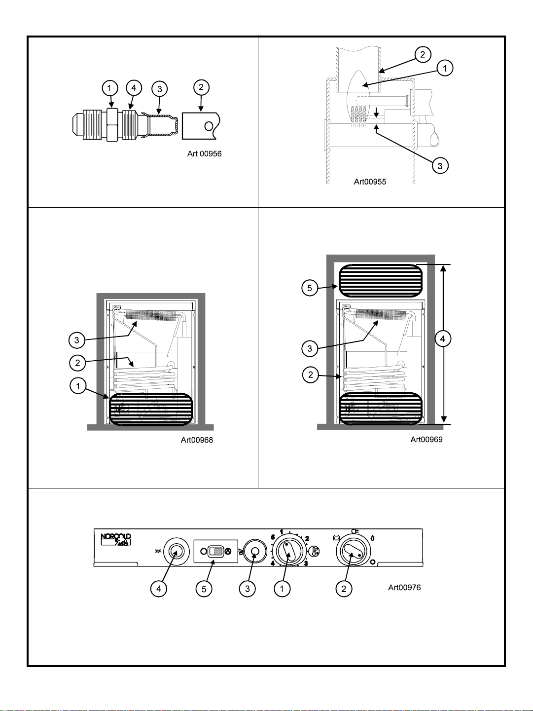
Controls........................................................................ 5
Ignition - propane gas operation ................................. 5
Do a test of the gas safety valve .................................. 5
Start up - AC operation ................................................. 5
Start up - DC operation (3-way models only)............... 6
DC Operation Precautions .......................................... 6
DC Operation Guidelines ............................................ 6
Shut down .................................................................... 6
Refrigerator Care Checklist ................................................ 5
Defrosting and Cleaning ..................................................... 6
Defrosting..................................................................... 6
Cleaning....................................................................... 6
Door Sealing ....................................................................... 7
Refrigerator Maintenance Checklist ................................... 7
Refrigerator Maintrenance .................................................. 7
Gas flame appearance ................................................ 7
Remove and clean the burner orifice .......................... 7
Remove the Refrigerator ..................................................... 8
Reinstall the Refrigerator .................................................... 8
Wiring Pictorial .................................................................... 9
Wiring Diagram ................................................................... 9
Replacement Parts ............................................................. 9
Norcold • P.O. Box 4248 • Sidney, OH • USA • 45365-4248
Provided it is properly installed, properly maintained and placed
under normal service and use, Norcold, Inc. warrants its
refrigeration equipment to be free from defects in material and
workmanship for three years with respect to the equipment’s
component parts, and for two years with respect to the labor to
repair or replace such parts, commencing from the original date
of purchase.
Limitations of warranty
1. This Warranty applies only to Norcold gas absorption
refrigerator operating equipment. This Warranty does not
extend to glassware, electric light bulbs, and replaceable
fuses.
2. This warranty does not apply to parts and assemblies that
have been subjected to misuse, improper installation,
improper or abnormal service, transit damage, recharging of
the cooling system, accident, fire, improper repair, tampering
or abuse.
3. Irrespective of the nature of the warranty protection offered or
claimed, the period of warranty shall in no case extend
beyond three years for component parts and two years for the
labor to repair or replace such parts, commencing from the
original date of purchase of the new equipment.
4. In order to obtain the remedy of repair and replacement, the
refrigerator must be brought to any Norcold Service Center for
warranty service. The end consumer is responsible for all
expenses resulting from any remote service call if the
refrigerator cannot be brought into the Norcold service center.
Installation Manual ................................................................... 9
Safety Awareness ............................................................... 9
Safety Instructions ............................................................... 9
Certification and Code Requirements .............................. 10
Ventilation Requirements ................................................. 10
Assemble the Enclosure ................................................... 11
Install the Lower and Upper Vents.....................................11
Install the Refrigerator ....................................................... 12
Installation Options ........................................................... 12
Install the decorative door panel ............................... 12
Reverse the door swing ............................................. 12
Connect the Electrical Components ................................. 13
Connect the 120 volts AC supply ............................... 1 3
Connect the 12 volts DC supply (3-way models only)13
Connect the chassis ground .................................... 1 3
Connect the Propane Gas Components .......................... 13
Connect the gas supply system ................................ 13
Examine the gas supply system for leaks ................ 14
Installation and Owner’s Manual 2
5. It is the responsibility of the end consumer to have maintenance performed upon the warranted equipment one time
during the second year or before the beginning of the third
year after original purchase. Such maintenance is required to
maintain this warranty in effect and failure to perform such
maintenance will void the remainder of the warranty. Required maintenance during the second year or before the
third year after purchase is cleaning and checking of the
following: Burner, Flue, Spiral Baffle, Roof Cap Screen, and
Control Board Sequence.
Limitation of remedy
1. The responsibility of Norcold under this or any warranty is
limited to the repair or replacement (at Norcold’s option) of
the defective part or assembly.
2. In no event and under no circumstances shall Norcold be
responsible under this limited warranty for any other charge
whatsoever, including but not limited to charges or claims for
labor, lost business, lost time, lost profits, loss of use, or any
kind of incidental or consequential damages, however
denominated or described. The remedy under this warranty
is limited to replacement or repair.
Page 3
3. Some states do not allow the exclusion or limitation of
incidental or consequential damages, so the above exclusion
may not apply to you.
Disclaimer of other warranties
This warranty is expressly in lieu of all other warranties either
expressed or implied. All other warranties, expressed or
implied, including any warranty of merchantability or fitness for a
particular purpose, are hereby disclaimed and excluded.
Legal rights
This warranty gives you specific legal rights, and you may have
other legal rights, which vary from state to state.
Gas Absorption Warranty Information
Your refrigerator is made to provide the ultimate in cooling
satisfaction and will serve you reliably in the years to come.
Norcold refrigerators are the only RV refrigerators made in the
United States and offer a standard limited three-year warranty.
Norcold also offers an additional warranty coverage plan which
extends the standard limited three-year warranty. To activate
your three-year limited warranty and to receive an invitation to
participate in the extended warranty plan, complete and mail the
warranty registration supplied.
Help us to help you.
Write the model number and serial number below for future
reference. These numbers are on the serial plate in the
refrigerator. The serial plate is located in the fresh food
compartment on the top right hand side. Use these numbers
when receiving service or in any correspondence concerning
your refrigerator.
Model number ___________ Serial number ___________
If a problem occurs with your refrigerator, contact any of the
service centers throughout the United States and Canada. To
find an authorized Norcold Service Center near you, please
telephone the Norcold Customer Support Dept. at 800-5431219 (option-1) or visit our web site at www.norcold.com.
Norcold is committed to providing products that are in harmony
with the environment. Your Norcold refrigerator meets all
environmental safety standards.
Gas Absorption Warranty Questions
This warranty is the only warranty for your Norcold refrigerator.
There are no other express warranties. The only uses for this
product are described in this manual. Part or model specifications are subject to change without notice.
What does this warranty cover?
This warranty covers labor and U.P.S. ground transportation
costs incurred in removing and reinstalling the refrigerator
when necessary to replace a defective part and any parts
replaced under warranty (including cooling units).
What is not covered by this warranty?
- Travel expenses for bringing the refrigerator to an authorized Norcold Service Center for warranty coverage.
- Additional costs caused by the inability to bring the
refrigerator to an authorized Norcold Service Center.
- Defects which are caused by transit damage, misuse,
neglect, or accident.
- Manufacturing defects found at the time of purchase, parts
replaced under warranty, and associated labor, which the
original consumer-purchaser do not communicate to
Norcold within 30 days.
- Labor, performed without need for parts replacements,
which the original consumer-purchaser does not communicate to Norcold within 30 days.
- Defects in glassware, electric light bulbs, or replacement
fuses.
- Defects caused by improper installation, maintenance, or
adjustment.
- Normal maintenance of this refrigerator as described in this
manual.
- Defects caused by the improper use of parts or parts not
manufactured or supplied by Norcold for repairs or replacements to the refrigerator.
Norcold will not be liable for any incidental or consequential
loss or damage, due directly or indirectly to the use of this
product. Some states do not allow the exclusion or limitation
of incidental or consequential damages, so the above may
not apply to you.
How long does this warranty last?
This warranty is effective for a period of two years from date of
purchase or for a period of three years from date of puchase if
the required maintenance is done.
What will Norcold do?
Norcold will provide free service and replacement of defective
parts, at no charge, at all authorized Norcold Service Centers.
Norcold has the option of replacing the defective parts or the
entire refrigerator. If the refrigerator is replaced, Norcold is
not responsible for replacing dealer installed options.
How do you get service?
Bring the refrigerator to any authorized Norcold Service Center
and:
- Show proof that the defective item is within warranty
coverage.
- Show proof that required maintenance has been performed
if applicable. Required maintenance during the second
year or before the third year after purchase is cleaning and
checking of the Burner, Flue, Spiral Baffle, Roof Cap
Screen, and Control Board Sequence.
If you are unable to bring the refrigerator to an authorized
Norcold Service Center:
- Send a written notice of the defect to Norcold.
- Norcold will promptly advise you how to obtain warranty
service.
What rights do you have?
This warranty gives you specific legal rights. You may also
have other rights which vary from state to state.
Installation and Owner’s Manual 3
Page 4
Safety Awareness
Read this manual carefully and understand the contents before
you use the refrigerator.
Be aware of possible safety hazards when you see the safety
alert symbol on the refrigerator and in this manual. A signal
word follows the safety alert symbol and identifies the danger of
the hazard. Carefully read the descriptions of these signal
words to fully know their meanings. They are for your safety.
WARNING: This signal word means a hazard, which if
ignored, can cause dangerous personal injury, death, or
much property damage.
CAUTION: This signal word means a hazard, which if
ignored, can cause small personal injury or much
property damage.
Safety Instructions
- The refrigerator cooling system is under pressure. Do
not try to repair or to recharge a defective cooling
system. The cooling system contains sodium chromate. The breathing of certain chromium compounds
can cause cancer. The cooling system contents can
cause severe skin and eye burns, and can ignite and
burn with an intense flame. Do not bend, drop, weld,
move, drill. puncture, or hit the cooling system.
CAUTION:
- The rear of the refrigerator has sharp edges and
corners. To prevent cuts or abrasions when working
on the refrigerator, be careful and wear cut resistant
gloves.
- Make sure all fasteners and connections are tight.
About Y our Refrigerator
Storage Volume:
WARNING:
- The storage of flammable materials behind or around
the refrigerator creates a fire hazard. Do not use the
area behind the refrigerator to store flammable
materials (gasoline, cleaning supplies, etc.)
- Do not remove the round ground prong from the
refrigerator AC power cord. Do not use a two prong
adapter or extension cord on the AC power cord.
- A circuit overload can result in an electrical fire if the
wires and/or fuses are not the correct size. Either use
the wire and fuse sizes as writtten in the “Installation
Manual” or refer to your local codes or the applicable
RVIA Standards for the correct wire and fuse sizes.
- Incorrect installation, adjustment, change to, or
maintenance of this refrigerator can cause personal
injury, property damage, or both. Have service and
maintenance work done by your dealer or by an
Norcold authorized service center.
- Disconnect both the AC and DC power sources before
doing any maintenance work on the refrigerator. All
service work on this refrigerator must be done by a
qualified service technician.
- Do not bypass or change the refrigerator’s electrical
components or features.
- When you discard an appliance, remove all doors to
prevent accidental entrapment and suffocation.
- Do not spray liquids near electrical outlets, connections, or the refrigerator components. Many liquids are
electrically conductive and can cause a shock hazard,
electrical shorts, and in some cases fire.
This refrigerator is made to store fresh and frozen foods and for
making ice.
Total capacity 2.7 cubic feet
Freezer capacity .4 cubic feet
Food compartment capacity 2.3 cubic feet
Leveling:
CAUTION:
off level side-to-side and 6° off level front-to-back (as
looking at the front of the refrigerator). Operating it at
more than these limits can cause damage to the cooling
system and create a risk of personal injury or property
damage. Make sure the vehicle is level before you
operate the refrigerator.
The refrigerator is made to operate within 3°
Food compartment:
Ignite or start up the refrigerator and let it cool for eight hours
before loading with food. If the refrigerator does not start to cool
down after about two hours, contact your dealer or a Norcold
authorized service center.
For the best cooling performance:
- Let air move freely inside the entire food compartment.
- Do not cover the shelves with plastic, paper, etc.
To decrease the amount of ice that collects on the cooling fins:
- Cover all liquids and moist foods.
- Let all hot foods cool before putting them in the refrigerator.
- Do not open the door any longer than necessary.
Installation and Owner’s Manual 4
Page 5
Freezer compartment:
- Put foods that are more likely to freeze on the upper shelf.
The freezer compartment is made to keep pre-frozen food
frozen and not to quick freeze food. Keep pre-frozen foods in
the freezer compartment.
NOTE: Do not put other items on the ice tray while the water is
freezing. The water freezes more rapidly if the
thermostat is at the coldest temperature setting.
Operation during travel:
While the refrigerator should be level when the vehicle is
stopped, performance during travel is not usually effected.
Door latch for travel and storage:
During travel, the door latch prevents the door from opening.
There are no chains, slides, or any devices that you must
engage.
During storage, the door latch prevents the door from completely closing. Use it to prevent odors when the refrigerator is
shut down for a long period of time.
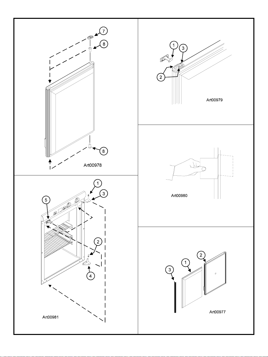
To use the door latch for storage (See Art00979):
- Open the door just so the door latch [1] is between the ribs
[2] of the latch plate [3].
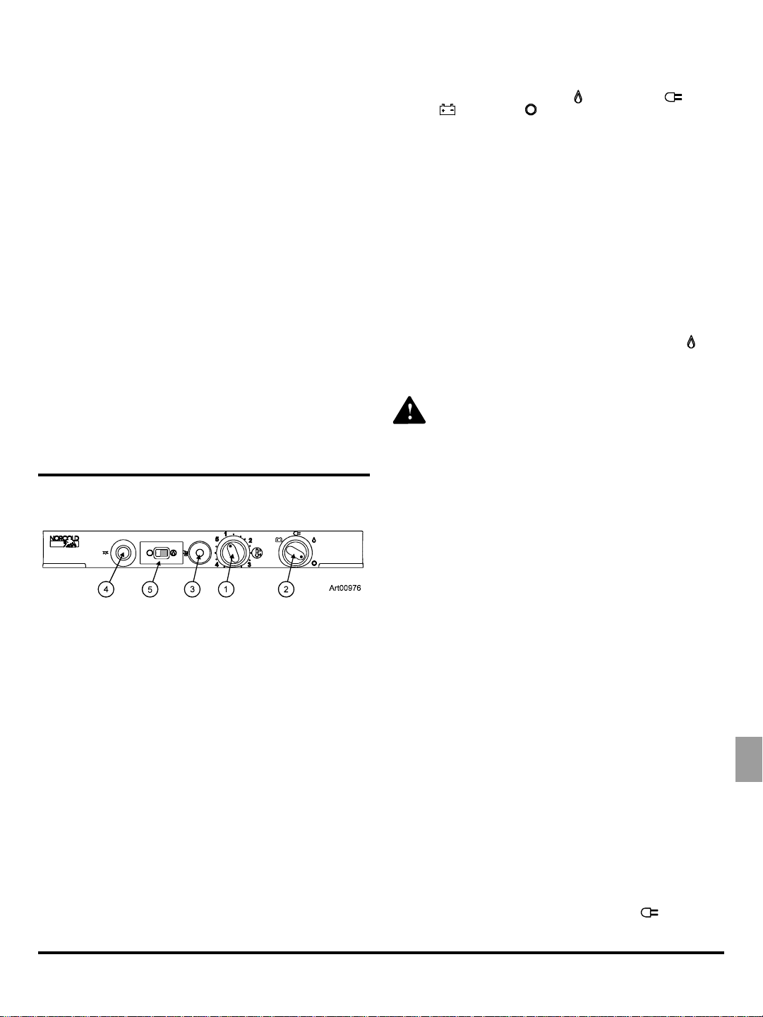
Ignition and Start Up
The selector switch [2] changes the energy source of the
refrigerator between propane gas (
electric (
The gas safety valve [3] is built into the control panel. As long
as a flame is present, the valve is open and allows propane
gas to flow into the burner. Any loss of flame (empty gas tank,
blow out, etc.) closes the safety valve and stops the flow of gas.
The piezo igniter [4] makes a spark which ignites the flame in
the burner.
The flame meter [5] shows if a flame is present in the burner.
), and OFF ( ).
), AC electric ( ), DC
Ignition - propane gas operation:
1. Open the valve at the gas storage tank.
2. Turn the thermostat to the 5 position.
3. Turn the selector switch to the propane gas position (
4. Push and hold in the safety valve and push in the igniter
several times in rapid succession, for about five seconds:
).
WARNING: Do not hold in the safety valve for more
than 30 seconds. If there is no flame in this time, wait at
least five minutes before you try ignition again. If you
continue to hold in the safety valve, gas will collect in the
burner area. This could cause a fire or explosion and
result in dangerous personal injury or death.
Controls:
Thermostat...........................................................................1
Selector switch ..................................................................... 2
Gas safety valve ................................................................... 3
Piezo lighter .........................................................................4
Flame meter ........................................................................ 5
The thermostat [1] (See Art00976) changes the amount of
propane gas that goes to the burner. This acts as the temperature control of the refrigerator. Number 5 is the coldest temperature setting.
NOTE: This is not an automatic gas control. It does not change
the flame from high fire to low fire as do some RV
refrigerators. If the cooling load changes, you must
manually change the gas control to maintain the same
temperature inside the refrigerator.
When the outside air temperature is below 50° F, the refrigerator may have a tendency to freeze food at the colder temperature settings. To reduce the tendency to freeze food:
- Turn the thermostat to a warmer temperature setting.
- When a flame is present and the flame meter moves into
the green area, release the safety valve.
- If the flame meter does not move into the green area, do
this step again.
5. Turn the thermostat to the temperature setting that you wish.
Do a test of the gas safety valve:
With an established flame in GAS mode:
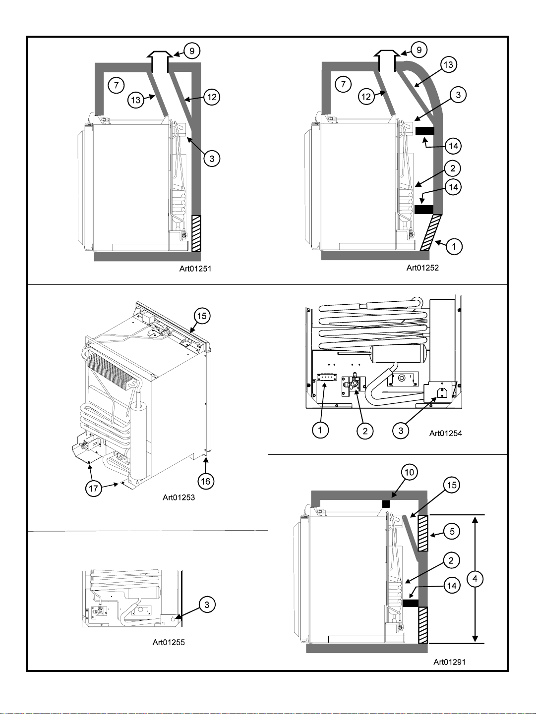
1. Close the manual gas shutoff valve [2] of the refrigerator
(See Art01254].
2. After the flame is extinguished, you should hear a sharp
“click” sound within three minutes.
NOTE: The gas safety valve should close with a sharp “click“
sound.
3. Open the manual gas shutoff valve of the refrigerator.
4. Without pushing in the gas control, push the igniter several
times rapidly in succession. The burner flame should not
ignite. This means that the gas safety valve is working
correctly.
Start up - AC operation:
- Make sure that 120 volts AC is available.
- Keep the refrigerator full.
- Turn the selector switch to the AC position (
- Turn the thermostat to the temperature setting that you
wish.
Installation and Owner’s Manual 5
).
Page 6
Start up - DC operation (3-way models only):
- Make sure that 12 volts DC is available.
- Turn the selector switch to the DC position (
).
DC Operation Precautions:
This refrigerator is made to operate on DC power while your
vehicle is “in transit” and AC power or propane gas sources
are not available. Operate the refrigerator on DC power only
when the vehicle engine is running.
For the refrigerator to operate correctly on DC power, the battery
must be maintained in a fully charged condition. For the battery
to be fully charged at all times during refrigerator operation on
DC, the vehicle engine
be in good operating condition.
must be running and the alternator must
- Be aware of any cooling changes that are not because of
weather, loading, or gas control changes. If changes occur,
contact your dealer or service center.
- Make sure the gas supply is propane gas only and not
butane or a butane mixture.
- When in propane gas operation, examine the appearance
of the flame. See “Gas Flame Appearance”.
- Make sure the air flow in the lower intake vent, through the
refrigerator condenser and coils and out the upper exhaust
vent is not blocked or decreased.
- Make sure the area behind the refrigerator is clear. Do not
use the area behind the refrigerator for storage of any
combustible materials, especially gasoline and other
flammable vapors and liquids.
Keep in mind the following electrical precautions for DC
operation of the refrigerator:
- Good battery condition is necessary for correct DC operation.
- The capacity of the battery charging system must be more
than what is necessary for the refrigerator and other DC
appliances.
- While the vehicle engine is running, have a qualified service
technician make sure the voltage of the DC power supply
leads at the refrigerator is more than 11.5 VDC.
DC Operation Guidelines:
DC operation is intended only to maintain the temperature of
the refrigerator and its contents when they are already cool.
The DC operation is not intended for the initial start up and
cooling of the refrigerator. Always use either the AC operation or
propane gas operation to initially start up and cool the refrigerator. The refrigerator must be cooled and the temperature must
be steady before you operate the refrigerator on DC.
Keep in mind the following guidelines for DC operation of the
refrigerator:
- Use DC operation of the refrigerator while the vehicle is in
transit.
- Do not use DC operation until the refrigerator and its
contents are completely cooled.
Shut down:
- Turn the selector switch to the OFF position ( ).
Defrosting and Cleaning
Defrosting:
It is normal for frost to collect on the cooling fins inside the
refrigerator. Excess frost decreases the cooling performance of
the refrigerator. Defrost the refrigerator as necessary:
- Turn the selector switch to the OFF position (
- Remove all food from the refrigerator.
NOTE: Defrosting the refrigerator makes excess water inside
the refrigerator.
- Put dry towels (etc.) inside the refrigerator to absorb the
water.
- Put trays of hot water in the freezer until the frost is melted.
- Empty the drip tray.
- Remove the wet towels (etc.) and dry the interior.
- Put the drip tray and all food in the refrigerator.
- Ignite or start up the refrigerator.
Cleaning:
A good time to clean the refrigerator is just after you defrost it.
Clean the inside of the refrigerator as often as necessary to
avoid food odors:
).
Refrigerator Care Checklist
Your refrigerator will give you years of trouble free service if you
do these simple checks every three to six months:
- Keep the food compartment and the freezer clean. See
“Defrosting and Cleaning”.
- Defrost the refrigerator as necessary. See “Defrosting and
Cleaning”.
- Make sure the door seals correctly. See “Door Sealing“.
Installation and Owner’s Manual 6
- Remove all food from the refrigerator.
NOTE: Do not use abrasive cleaners, chemicals, or
scouring pads because they can damage the
interior of the refrigerator.
- Wash the interior with a solution of liquid dish detergent
and warm water.
Page 7
Door Sealing
If the door does not seal correctly, excess frost will collect inside
the refrigerator. Make sure the door seals correctly:
- Close the door on a piece of paper that is about the size of
a dollar bill (See Art00980).
- Gently pull the paper.
- You should feel a slight drag between the gasket and
the cabinet.
- Do this on all four sides of the door.
- If you do not feel a slight drag on the
paper, the door is not sealing correctly:
- Make sure the screws of the hinges are tight.
- Make sure the door gasket does not touch the door
latch:
- If the door gasket touches the door latch,
loosen the screws of the door latch.
- Raise the door latch just so it does not touch
and tighten the screw s of the door latch.
- Make sure the door latch holds the door closed.
Refrigerator Maintenance Checklist
- Make sure the AC and DC voltages are correct.
- Adjust if needed.
- Make sure the thermocouple tip is clean and secure.
- Make sure the area at the rear of the refrigerator is free of
any combustible materials, gasoline, and other flammable
vapors and liquids.
Refrigerator Maintenance
Gas flame appearance:
While in propane gas operation, examine the appearance of the
gas flame:
- Turn the thermostat to the 5 position.
- Open the lower intake vent.
CAUTION: The burner box cover can be hot. Wear
gloves to avoid burns.
- Open the burner box door [3] and look at the gas flame [1]
(See Art00955 and Art01255).
- The flame should be a darker blue inside and a lighter
blue outside and should be a constant and steady
shape.
- If the flame is yellow or has an erratic and unstable
shape, contact your dealer or Norcold authorized
service center.
Read and understand the following maintenance sections of this
manual.
NOTE: Norcold is not responsible for installation, adjust-
ment, alteration, service, or maintenance performed
by anyone other than a qualified RV dealer or a
Norcold authorized service center.
Have a qualified RV dealer or a Norcold authorized service
center do these annual safety and maintenance checks:
- Examine the gas supply lines for leaks.
- Replace or repair if needed.
- Make sure the propane gas pressure is correct.
- Adjust if needed.
- Make sure the combustion seal is complete and intact.
- Replace or repair it if needed.
- Make sure the burner and the burner orifice are clean (See
Art00956).
- Clean if needed.
- Make sure the electrode spark gap [3] is 1/8 - 3/16 inch
(See Art00955).
- Adjust if needed.
- Make sure the flame does not touch the inside of the
flue tube [2].
- If the flame touches the inside of the flue tube, contact
your dealer or Norcold authorized service center.
- Close the burner box door.
Remove and clean the burner orifice:
NOTE: Your dealer or Norcold authorized service center must
To remove and clean the burner orifice:
do this procedure.
- Close the valve at the gas tank(s).
- Close the manual shut off valve of the refrigerator.
- Turn the selector switch to the OFF position (
- Open the lower intake vent.
- Remove the burner box cover by removing one screw.
).
WARNING: To avoid possible propane gas leaks,
always use two wrenches to loosen and tighten the
gas supply line at the refrigerator’s manual shut off
valve.
- Remove the flare nut from the orifice assembly [1] (See
Art00956).
Installation and Owner’s Manual 7
Page 8
- Remove the orifice assembly from the burner [2].
WARNING: Do not try to remove the orifice [3] from the
orifice adapter [4] when cleaning. Removal will
damage the orifice and seal of the orifice and can
cause a propane gas leak. Leaking propane gas can
ignite or explode which can result in dangerous
personal injury or death. Do not clean the orifice with a
pin or other objects.
- Clean the orifice assembly with air pressure and alcohol
only.
- Using a wrench, assemble the orifice assembly to the the
burner.
- Assemble the flare nut to the orifice assembly.
- Examine all of the connections for gas leaks.
Remove the Refrigerator
NOTE: Your dealer or Norcold authorized service center must
do this procedure.
CAUTION: The rear of the refrigerator has sharp edges
and corners. To prevent cuts or abrasions when working
on the refrigerator, be careful and wear cut resistant
gloves.
1. Close the valve at the gas tank(s).
Reinstall the Refrigerator
NOTE: Your dealer or Norcold authorized service center must
do this procedure.
WARNING: Make sure the combustion seal is not
broken, is completely around the refrigerator mounting
flanges, and is between the mounting flanges and the
wall of the enclosure. If the combustion seal is not
complete, exhaust fumes can be present in the living
area of the vehicle. The breathing of exhaust fumes can
cause dizziness, nausea, and in extreme cases, death.
1. Push the refrigerator completely into the enclosure.
2. Remove the door from the refrigerator.
3. Put the screws though the mounting flanges and into the
wall.
4. Put the plastic plugs into the mounting flanges of the
refrigerator.
5. Attach the door to the refrigerator
CAUTION: The rear of the refrigerator has sharp edges
and corners. To prevent cuts or abrasions when working
on the refrigerator, be careful and wear cut resistant
gloves.
6. Open the lower intake vent and put the screws through
refrigerator and into the floor.
WARNING: To avoid possible propane gas leaks,
always use two wrenches to loosen and tighten the gas
supply line at the refrigerator’s manual shut off valve.
2. Open the lower intake vent and remove the gas supply line
from the manual shut off valve of the refrigerator.
3. Remove the AC power cord from the receptacle.
4. Remove the DC wiring from the refrigerator:
- Put a mark on the DC wires so you can put them back in
the correct location.
- Remove the DC fuse or remove the DC wiring from the
battery or the converter of the vehicle.
- Remove the DC wires from the refrigerator.
5. Remove the screws which fasten the refrigerator to the floor.
6. Remove the plastic plugs from the mounting flanges of the
refrigerator.
7. Remove the door from the refrigerator.
8. Remove the screws which fasten the refrigerator to the wall.
9. Remove the refrigerator from the opening.
10. Attach the door to the refrigerator.
WARNING: To avoid possible propane gas leaks,
always use two wrenches to loosen and tighten the gas
supply line at the refrigerator’s manual shut off valve.
7. Attach the gas supply line to the manual shut off valve of the
refrigerator.
8. Open the valve at the gas tank(s).
WARNING: Do not allow the leak checking solution to
touch the electrical components. Many liquids are
electrically conductive and can cause a shock
hazard,electrical shorts, and in some cases fire.
9. Examine the gas supply line for leaks.
10. Connect the DC wiring to the refrigerator:
- Install the DC fuse or connect the DC wiring to the battery or
the converter.
- Connect the DC wires from the refrigerator.
11. Connect the AC power cord to the receptacle.
Installation and Owner’s Manual 8
Page 9
Wiring Pictorial
Installation Manual
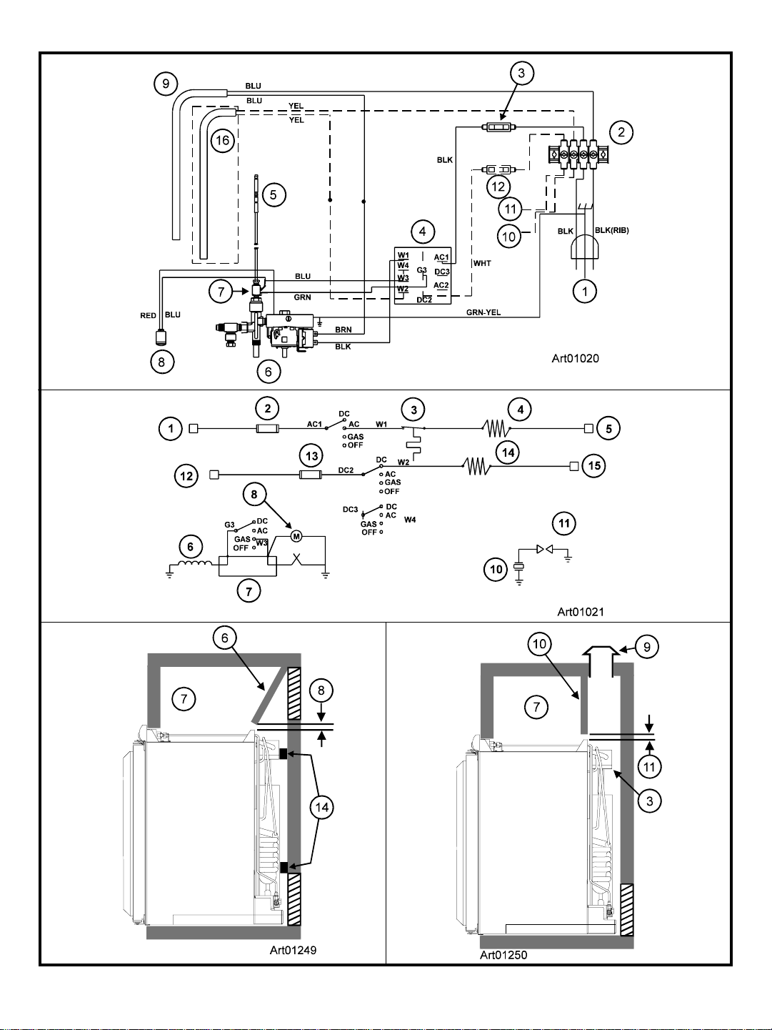
The parts of the wiring pictorial are (Art01020):
1 ............................................................ 120VAC Power cord
2 ..................................................................... Terminal block
3 .......................................................................... 3 Amp fuse
4 .................................................................... Selector switch
5 ......................................................................Thermocouple
6 ............................................. Thermostat / gas safety valve
7 .................................................... Thermocouple interrupter
8 ........................................................................ Flame meter
9 ............................................................................ AC heater
10 .................... -12 VDC Power supply (3-way models only)
11 .................... +12 VDC Power supply (3-way models only)
12 .....................................20 Amp fuse (3-way models only)
16 .........................................DC heater (3-way models only)
Wiring Diagram
The parts of the wiring diagram are (See Art01021):
1 .............................................................................. 120 VAC
2 .......................................................................... 3 Amp fuse
3 .......................................................................... Thermostat
4 ............................................................................ AC heater
5 .............................................................................. 120 VAC
6 ..................................................................Gas safety valve
7 .................................................... Thermocouple interrupter
8 ........................................................................ Flame meter
10 ....................................................................... Piezo lighter
11 .......................................................................... Spark gap
12 .......................................... +12 VDC (3-way models only)
13 .....................................20 Amp fuse (3-way models only)
14 ......................................... DC heater (3-way models only)
15 ................................... -12 VDC Com (3-way models only)
17 .................................................................. Selector switch
Replacement Parts
You may purchase replacement parts through your local RV
dealer or authorized Norcold Service Center.
Safety Awareness
Read this manual carefully and understand the contents before
you install the refrigerator.
Be aware of possible safety hazards when you see the safety
alert symbol on the refrigerator and in this manual. A signal
word follows the safety alert symbol and identifies the danger of
the hazard. Carefully read the descriptions of these signal
words to fully know their meanings. They are for your safety.
WARNING: This signal word means a hazard, which if
ignored, can cause dangerous personal injury, death, or
much property damage.
CAUTION: This signal word means a hazard, which if
ignored, can cause small personal injury or much
property damage.
Safety Instructions
WARNING:
- This refrigerator is equipped for the use of propane gas
only and can not be changed to use any other fuels
(natural gas, butane, etc.).
- Incorrect installation, adjustment, alteration, or maintenance of this refrigerator can cause personal injury,
property damage, or both.
- Obey the instructions in this manual to install the intake
and exhaust vents.
- Do not install the refrigerator directly on carpet. Put the
refrigerator on a metal or wood panel that extends the full
width and depth of the refrigerator.
- Propane gas can ignite and cause an explosion that can
result in property damage, personal injury, or death. Do
not smoke or create sparks while working on the gas
supply system. Do not use an open flame to examine
the gas supply piping or fittings for leaks.
- To avoid possible propane gas leaks, always use two
wrenches to tighten or loosen the gas suppy line
connections.
- Make sure the electrical installation obeys all applicable
codes. See “Certification and Code Requirements”
section.
- Do not bypass or change the refrigerator’s electrical
components or features.
- Do not spray liquids near electrical outlets, connections,
or the refrigerator components. Many liquids are electrically conductive and can cause a shock hazard, electrical
shorts, and in some cases fire.
Installation and Owner’s Manual 9
Page 10
- The refrigerator cooling system is under pressure. Do not
try to repair or to recharge a defective cooling system.
The cooling system contains sodium chromate. The
breathing of certain chromium compounds can cause
cancer. The cooling system contents can cause severe
skin and eye burns, and can ignite and burn with an
intense flame. Do not bend, drop, weld, move, drill,
puncture, or hit the cooling system.
All gas supply piping and fittings must obey local, state, and
national codes about type and size. These components must
also obey the current NFPA 501C section 2-4, and in Canada,
the current CAN 1-6.10 Standard.
Ventilation Requirement s
CAUTION:
- The rear of the refrigerator has sharp edges and corners.
To prevent cuts or abrasions when working on the
refrigerator, use caution and wear cut resistant gloves.
Certification and Code Requirements
This refrigerator is certified under the latest edition of ANSI
Z21.19 Standards by the American Gas Association for installation in mobile homes or recreational vehicles and is approved by
the Canadian Gas Association.
The installation must obey these standards and this “Installation
Manual” for the NORCOLD limited warranty to be in effect.
Installation must agree with local codes. In the absence of local
codes, the installation must obey these standards:
In the United States:
- National Fuel Gas Code, ANSI Z223.1.
- Manufactured Home Construction and Safety Standard,
Title 24 CFR, Part 32-80.
- Standard for Recreational Vehicles, RVIA A119.2 latest
edition.
- For installations which need an electric outlet that is
energized by an external power source, the refrigerator
must be electrically grounded as writen in local or state
codes, the National Electrical code, and ANSI/NFPA 70.
In Canada:
- Current CGA B149.1 and CGA B149.2 Installation code for
Propane Appliances and Equipment.
- Current CSA Z240.4.2 Installation Requirement for Propane
Appliances and Equipment in Recreational Vehicles.
- Current CSA Z240.6.2/C22.2 No. 148 Electrical
Requirement for Recreational Vehicles.
WARNING: The completed installation must:
- Make sure there is sufficient intake of fresh air for
combustion.
- Make sure the living space is completely isolated from
the combustion system of the refrigerator.
- Make sure there is complete and unrestricted ventilation of the flue exhaust which, in gas mode, can
produce carbon monoxide. The breathing of carbon
monoxide fumes can cause dizziness, nausea, or in
extreme cases, death.
- Make sure the refrigerator is completely isolated from
its heat generating components through the correct use
of baffles and panel construction.
Certified installation needs one lower intake vent and one upper
exhaust vent. Install the upper exhaust vent either through the
roof or through the side wall of the vehicle exactly as written in
this manual. Any other installation method voids both the
certification and the factory warranty of the refrigerator.
The bottom of the opening for the lower intake vent, which is
also the service access door, must be even with or immediately
below the floor level. This allows any leaking propane gas to
escape to the outside and not to collect at floor level.
American Gas Association/Canadian Gas Association (AGA/
CGA) certification allows the refrigerator to have zero (0) inch
minimum clearance at the sides, rear, top, and bottom. While
there are no maximum clearances specified for certification, the
following maximum clearances are necessary for correct
refrigeration:
Bottom 0 inch min. 0 inch max.
Each Side 0 inch min 1/8 inch max.
Top 0 inch min. 1/4 inch max.
Rear 0 inch min. 1 inch max.
These clearances plus the lower and upper vents cause the
natural air draft that is necessary for good refrigeration. Cooler
air comes in through the lower intake vent, goes up around the
refrigerator coils where it removes the excess heat from the
refrigerator components, and goes out through the upper
exhaust vent. If this air flow is blocked or decreased, the
refrigerator will not cool correctly.
Each NORCOLD model is certified by AGA and CGA for correct
ventilation.
- When installed, the refrigerator must be electrically
grounded as written in the local or state codes, and the
Canadian Electrical Code C22.2. Parts 1 and 2.
Installation and Owner’s Manual 10
Page 11
Assemble the Enclosure
- Make sure the baffle is the full width of the inside of
the enclosure.
- Make sure the enclosure is 29 3/4 inches high x 20 1/2
inches wide x 21 3/8 inches deep.
- Make sure the floor is solid and level.
- The floor must be metal or a wood panel and extend
the full width and depth of the enclosure.
- The floor must be able to support the weight of the
refrigerator and its contents.
- Make sure there are no adjacent heat sources such as a
furnace vent, etc.
Install the Lower and Upper Vents
1. Using the following chart, decide which vents and rough
opening (RO) sizes to use.
Certified Vent P/N RO Height RO Width
Upper Roof 622293 24 in. 5 1/4 in.
Exhaust Vent
Upper Side 617485 7 1/4 in. 18 in.
Exhaust Vent
Lower Side 617484 9 3/4 in. 19 3/8 in.
Intake Vent
2. Install the lower intake vent (See Art 00968):
WARNING: Make sure the bottom of the opening of the
lower intake vent is even with or immediately below the
floor level. This allows any leaking propane gas to
escape to the outside and not to collect at floor level.
- Make sure the bottom of the opening of lower intake vent is
even with or immediately below the floor level.
- Align the lower intake vent [1] vertically below the coils [2]
and the condenser [3] of the refrigerator.
3. Install the upper exhaust vent (see Art00969):
- If you install the upper side exhaust vent:
- Make sure the distance [4] from the floor level to the
top of the rough opening for the upper exhaust vent is
at least 37 inches or poor cooling performance can
occur.
- Align the upper exhaust vent [5] vertically above the
coils [2] and the condenser [3] of the refrigerator.
- Install a baffle [6] to prevent stagnant hot air in the area
[7] above the refrigerator (see Art01249).
- Make sure there is less than 1/4 inch clearance [8]
between the baffle and the top of the refrigerator.
- If the construction of the vehicle does not allow the
distance [4] to be 37 inches, the distance (optional
only) can be as little as 30 3/4 inches (See Art01291) if
you:
- Install a baffle [15] from the lower edge of the
upper exhaust vent [5] to the top edge of the
condenser fins.
- Make sure the baffle is not below the top edge of
the condenser fins.
- Install a baffle [14] from the upper edge of the
lower exhaust vent that is firmly against the
absorber coils [2] of the refrigerator.
- Install a baffle [10] to prevent any stagnant hot air in
the area above the refrigerator.
- If you install the roof exhaust vent (See Art01250):
CAUTION: Make sure that no sawdust, insulation, or
other construction debris is on the refrigerator or in the
enclosure. Debris can cause a combustion hazard
and prevent the refrigerator from operating correctly.
NOTE: Tighten the screws of the roof cap to 10 inch-pounds
max.
- If the design of the vehicle allows, install the roof
exhaust vent [9] directly above the condenser [3] of the
refrigerator.
- Install a baffle [10] to prevent stagnant hot air in the
area [7] above the refrigerator.
- Make sure there is less than 1/4 inch clearance [11] between the baffle and the top of the
refrigerator.
- Make sure the baffle is the full width of the
inside of the enclosure.
- If the design of the vehicle does not allow you to install
the roof exhaust vent directly above the condenser of
the refrigerator:
- Center the roof exhaust vent [9] above the condenser [3] of the refrigerator, but move it inboard
as necessary (see Art01251).
- Install two baffles [12] and [13] to prevent stagnant
hot air in the area [7] above the refrigerator.
- Make sure both baffles are the full width of the
inside of the enclosure.
- Make sure that both baffles are no more than
45° from vertical.
- Put one baffle between the top rear edge of the
refrigerator and the inside edge of the upper
exhaust vent opening.
- Put the other baffle between the outside edge
of the upper exhaust vent opening and the
side wall of the vehicle.
Installation and Owner’s Manual 11
Page 12
Install the Refrigerator
1. Make sure the clearance at the rear of the refrigerator is
correct:
- If there is more than 1 inch of clearance between the rear of
the refrigerator and the enclosure, install two baffles [14] to
the rear of the enclosure (See Art01249 and Art01252).
- Put one baffle at the top edge of the lower intake vent
[1].
- Put the other baffle at the lower edge of the condenser
[3] of the refrigerator.
- Make sure the baffles are less than 1/4 inch from the
coils [2] and condenser of the refrigerator.
- Make sure the baffles are the full width of the
inside of the enclosure.
2. Put the refrigerator in position (see Art01253):
WARNING: Make sure the combustion seal [15] is not
broken, is completely around the refrigerator mounting
flanges [16], and is between the mounting flanges and
the wall of the enclosure. If the combustion seal is not
complete, exhaust fumes can be present in the living
area of the vehicle. The breathing of exhaust fumes can
cause dizziness, nausea, or in extreme cases, death.
- Remove the door from the refrigerator (See “Reverse the
door swing” section).
- Put screws through the holes of the refrigerator mounting
flanges and into the enclosure wall.
- Attach the door to the refrigerator.
- Put a screw through the holes [17] in the braces at the lower
rear corners of the refrigerator and into the floor.
- Turn out and save the upper hinge pin [1].
- Open the door a small amount and pull the top of the door
away from the upper hinge of the refrigerator.
- Lift the door off of the lower hinge pin [2].
- Turn out and save the lower hinge pin.
2. Change the position of the hinges:
- Remove and save the plastic bushings that are in the holes
on the ends of the door..
- Remove the screws from the upper hinge [3].
- Put this hinge on the other side as the lower hinge.
- Attach the hinge with the screws.
- Turn the lower hinge pin down into this hinge.
- Remove the screws from the lower hinge [4].
- Remove the screw from the travel latch [5].
- Put this hinge on the other side as the upper hinge.
- Attach the hinge with the screws.
- Push the bushings into the empty holes in the ends of the
door.
3. Change the position of the travel latch (See Art00978 and
Art00981):
- Put the travel latch on the other side of the refrigerator.
- Attach the travel latch with the screw.
- Remove the screw from the travel latch plate [7] on the
door.
Installation Options
Install the decorative door panel:
NOTE: The decorative panels must be 3/16 inch or less in
thickness.
- Make a decorative door panel [1] that is 25 15/16 inches
high x 20 1/8 inches wide (See Art00977).
- Push the decorative door panel into the slots of the door
end caps [2].
- Push each panel retainer [3] into the slot on the edge of the
door.
Reverse the door swing:
This refrigerator has door hinges that allow you to change the
direction that the door opens by moving the hinges to the
opposite corner (See Art00981).
1. Remove the door:
Installation and Owner’s Manual 12
- Pull each hinge bushing [8] out of the hole in the door.
- Pull the plastic plug out of the top of the door.
- Push the plastic plug into the other hole in the top of the
door.
- Put the travel latch plate on the other side of the door.
- Attach the travel latch plate with the screw.
- Push each hinge bushing into the hole on the other side of
the door.
4. Install the door:
- Put the door down onto the lower hinge pin.
- Align the holes in the upper hinge and the hinge bushing
and hold in this position.
- Screw the upper hinge pin down into the upper hinge and
into the door.
Page 13
- Tighten all of the screws.
- Make sure the travel latch engages the travel latch plate.
- If not, loosen the screw and adjust the height of the
travel latch plate.
- Tighten the screw.
Connect the Electrical Components
AC Operation 120 volts AC voltage
Current Draw 1.4 Amps at 110 Volts AC
DC Operation 12 volts DC voltage
(3-way models only) (11.5 volts min. - 15.4 volts max.)
Current Draw 12 Amps at 12 Volts DC
This refrigerator operates on both AC and DC electrical
sources. Operation out of these limits may damage the
refrigerator’s electrical circuit parts and will void the warranty.
Connect the 120 volts AC supply:
WARNING:
grounded three-prong receptacle. Do not remove the
round ground prong from the power cord. Do not use a
two-prong adapter or an extension cord. Operation of the
refrigerator without correct ground can cause dangerous
electrical shock or death if you are touching the metal
parts of the refrigerator.
Put the AC power cord into a grounded three-prong receptacle:
- Make sure the receptacle is positioned within easy reach of
the lower intake vent.
- Make sure the power cord does not touch the burner cover,
the flue pipe, or any hot component that could damage the
insulation of the power cord.
Connect the 12 volts DC supply (3-way models only):
As the distance from the vehicle battery to the refrigerator
increases, the correct AWG wire size and fuse size also
increases. If the wire size is too small for the distance, a
voltage drop occurs. The voltage drop decreases the output of
the system heater and causes decreased cooling performance.
WARNING: A circuit overload can result if the wires and/
or fuses are not the correct size. Refer to your local
codes or the applicable RVIA Standards for the correct
wire and fuse sizes.
1. For the best performance, Norcold recommends that you
use the following wire and fuse sizes:
- Measure the distance from the vehicle battery to the
refrigerator:
(108 volts min. - 132 volts max.)
1.5 Amps at 120 Volts AC
14 Amps at 14 Volts DC
Connect the AC power cord only to a
- If the distance is 0 - 20 feet, use #12 AWG min. wire
size and a 20 amp max. fuse.
- If the distance is over 20 feet, use #10 AWG min. wire
size and a 30 amp max. fuse.
The wire connections must be clean, tight and free of
corrosion. If any of these items are not correct:
- A voltage drop to the refrigerator will occur.
- The voltage drop will reduce the cooling performance of the
refrigerator.
The terminals for connecting the DC power supply are marked
positive (+) and negative (-) on the terminal block of the refrigerator. Make sure that:
- Each DC power supply wire is attached to the correct
polarity terminal.
- The chassis or the vehicle frame is not used as one of the
conductors.
- The DC power supply wires including the fuses are routed
directly from the battery to the refrigerator.
2. Connect the D.C. power supply wires:
- Attach a 1/4 inch Quick Connect terminal to each DC power
supply wire.
- Push each power wire onto the terminal block [1] at the rear
of the refrigerator (See Art00975).
- Make sure each DC power supply wire is on the correct
polarity terminal.
Connect the chassis ground:
Connect a ground wire between the refrigerator and the vehicle
chassis:
- Use #8 AWG wire with a #8 ring terminal for the ground
wire.
- Remove the nut and washer from the grounding terminal of
the refrigerator.
- Put the ground wire, the washer, and nut on the terminal.
- Tighten the nut.
Connect the Propane Gas Components
This refrigerator operates on propane gas at a pressure of 11
inches Water Column Propane.
Connect the propane gas supply system:
WARNING:
the propane gas system.
Be very careful when working on or near
- Do not smoke or use an open flame near the propane
gas system.
Installation and Owner’s Manual 13
Page 14
- Do not use an open flame to examine for leaks.
- Do not connect the refrigerator to the gas tank without a
pressure regulator between them.
- To avoid an propane gas leak, always use two
wrenches to tighten or loosen the gas supply line
connections.
- Leaking propane gas can ignite or explode and result
in dangerous personal injury or death.
Connect the gas supply line to the refrigerator:
- Make sure all tubing and fittings obey all local, state, and
national codes about size and type.
- Make sure that all flexible metal connectors obey the current
CAN1-6.10 Standard.
- Use 3/8” diameter copper tubing as the gas supply line and
use a 3/8” SAE (UNF5/8 -18) female flare fitting as the
connection to the refrigerator.
- Put the gas supply line up through the floor of the enclosure
and in a manner to prevent vibration and abrasion.
- Make sure the hole through the floor is large enough to
allow clearance for the gas supply line.
- Put a weather resistant seal (grommet, sealant, etc.)
around the gas supply line where it goes through the floor
to prevent vibration and abrasion.
- Attach the gas supply line to the bulkhead fiting [2] of the
refrigerator (See Art01254).
Examine the gas supply system for leaks:
WARNING: Do not allow the leak detecting solution to
touch the electrical components. Many liquids are
electrically conductive and can cause a shock hazard,
electrical shorts, and in some cases, fire.
Use a solution of liquid detergent and water to examine the gas
supply line and all gas connections for leaks.
If you use compressed air for the test:
- The pressure at the manual shut off valve of the refrigerator
must not be more than 1/2 psig (14 inches Water Column).
- If the air pressure is more than 1/2 psig (14 inches Water
Column), remove the gas supply line from the bulkhead
fitting of the refrigerator before the test.
- If the air pressure is equal to or less than 1/2 psig (14
inches Water Column), close the manual shutoff valve of
the refrigerator before the test.
Installation and Owner’s Manual 14
Page 15
Page 16
Page 17
Page 18
 Loading...