

Norcold 8682, 8683, 8652, 8662, 8663 Repair Manual
...
A008
Manual Compliments of
Northwest RV Supply
Printed From
http://www.nwrvsupply.com
Table of Contents
Page
Norcold Repair Guide
Models 865,866,868
5-2 General Information and Specifications
5-2 Operating Limits - All Models
5-2 Ratings
5-3 Electrical Connections - 12 Volts DC
5-3 Electrical Connections - 120 Volts AC
5-4 Description of Operation
5-4 Control Description
5-4 LP Gas Mode
Section 5
5-4 AC Electric Mode
5-4 DC Electric Mode
5-5 Operating and Lighting Instructions
5-5 Important Information on 12 Volt Operation
5-7 Location of Controls
5-8 Parts Function
5-15 Troubleshooting
5-15 LP Gas Mode of Operation
5-21 AC Electric Mode of Operation
5-26 DC Electric Mode of Operation
5-30 Illustrations of Normal and Abnormal Conditions
5-34 Wiring Diagrams 2-Way, 8662, 8682
5-35 Wiring Diagrams 3-Way, 8663, 8683
5-36 Wiring Diagrams 2-Way, 8652
5-37 Wiring Diagrams 3-Way, 8653
5-1
General Information and Specification
Manual Compliments of
Northwest RV Supply
Printed From
http://www.nwrvsupply.com
OPERATING LIMITS - ALL
MODELS
AC Mode: 132 VAC Max., 108
VAC Min.
15. 4 VDC Max., 10.5
VDC Min.
DC Mode: 15.4 VDC Max., 11.5
VDC Min.
Gas Mode: 11" W.C.
15.4 VDC Max., 10.5
VDC Min.
MODELS 8652, 8653
RATINGS
1200 Btu/Hr Input
LP Gas Mode:
11" W.C.
LP14 Orifice
12 Volts DC control voltage
AC Mode:
110 Volts AC, 170 Watts
12 Volts DC control voltage
DC Mode (3-Way only):
12 Volts DC
MODELS 8662, 8663
RATINGS
1450 Btu/Hr Input
LP Gas Mode:
11" W.C.
LP16 Orifice
12 Volts DC control voltage
AC Mode:
110 Volts AC, 300 Watts
12 Volts DC control voltage
DC Mode (3-Way only):
12 Volts DC
MODELS 8682,8683
RATINGS
1500 Btu/Hr Input
LP Gas Mode:
11" W.C.
LP16 Orifice
12 Volts DC control voltage
AC Mode:
110 Volts AC, 300 Watts
12 Volts DC control voltage
DC Mode (3-Way only):
12 Volts DC
CURRENT DRAWS - 8652, 8653
Automatic ignition - Less than 250 milliamps or .25 amps
AC Heating Element - 1.5 amps at 110 Volts AC
1.7 amps at 120 Volts AC
DC Heating Element - 9.2 amps at 12 Volts DC
10.7 amps at 14 Volts DC
CURRENT DRAWS - 8662, 8663, 8682, 8683
Automatic ignition - Less than 250 milliamps or .25 amps
Humidity Heater - 240 milliamps or .24 amps
Interior Lamp (when door open) - 900 milliamps or .90 amps
AC Heating Element - 2.7 amps at 110 Volts AC
2.9 amps at 120 Volts AC
DC Heating Element - 13.8 amps at 12 Volts DC
16.1 amps at 14 Volts DC
OPERATION WHERE THESE SPECIFICATIONS ARE EXCEEDED MAY
CAUSE DAMAGE AND WILL VOID REFRIGERATOR WARRANTY.
5-2
Electrical Connections -
Manual Compliments of
Northwest RV Supply
Printed From
http://www.nwrvsupply.com
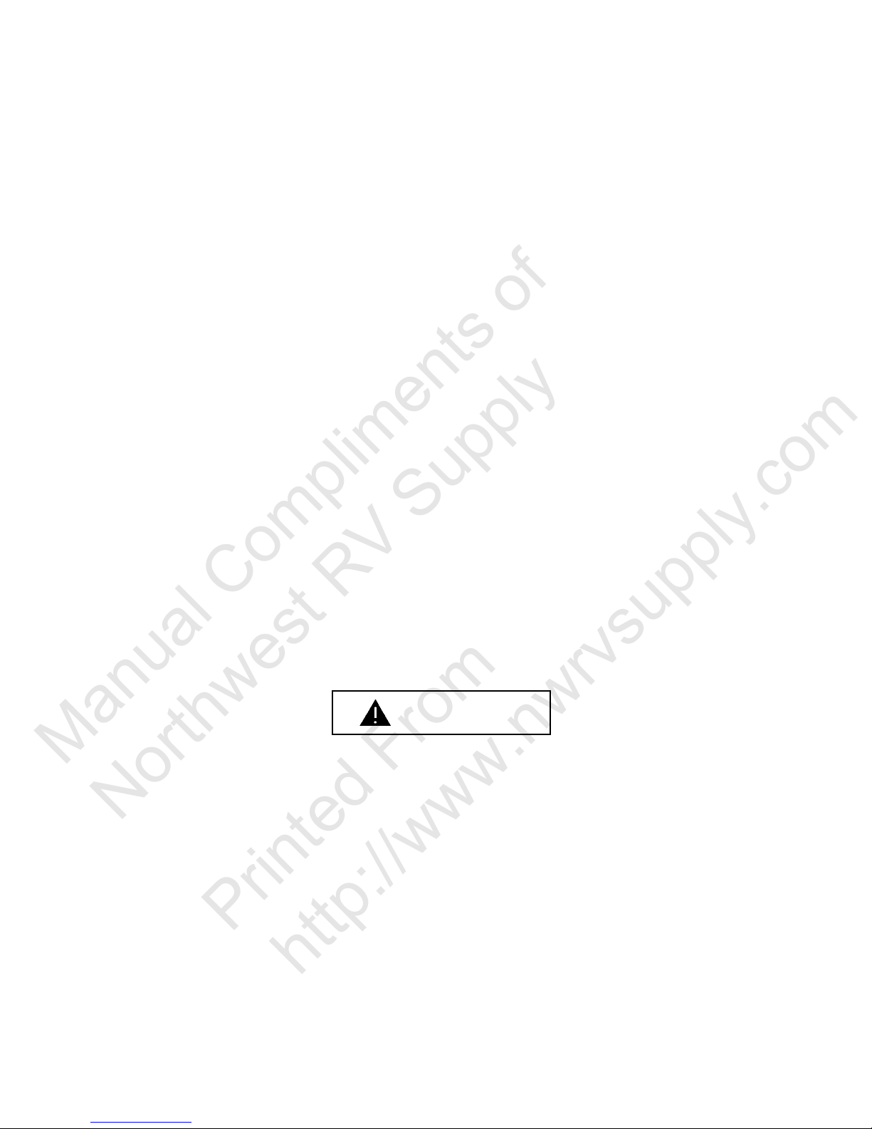
12 Volt DC
All Norcold refrigerator models require
a 12 volt DC supply (See Figure 5.1). 12
Volts DC is required to operate the
Mode Selector (Eyebrow board) and
temperature control circuits and maintain
the automatic Ignition gas mode. The
DC lead connections (1/4" male quick
connects) are at terminals located on the
Power Supply at the rear of the refrigerator. One terminal is marked positive (+)
and the other negative (-). Correct polarity must be observed when connecting
to the DC supply. Do not use the chassis
or vehicle frame as one of the conductors. Connect two wires between the refrigerator and the DC supply.
The distance the current must travel
from the battery to the refrigerator
dictates the AWG wire size to be
used. Should the wire be too small
for the distance, a voltage drop will
result. In the case of 3 - way models,
the voltage drop affects the wattage
output of the cartridge heater and resultant refrigerator performance. See
the adjacent wire and fuse chart for
the correct wire and fuse size.
Figure 5.1 Recommended 12 Volt Connection
TENSION CORDS ARE NOT RECOMMENDED.
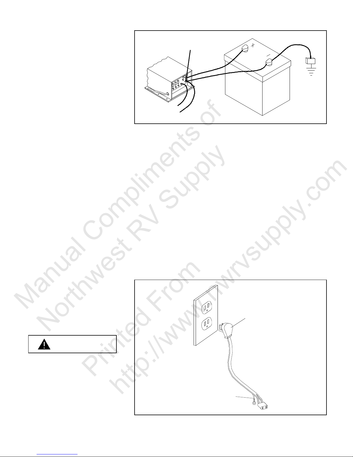
Electrical Connections 120 Volt AC
All Norcold refrigerators are equipped
with a three prong plug for protection
against shock hazard (See Figure 5.2).
They must be connected into a recognized three prong attachment receptacle. The cord must be routed so as not
to come in contact with the Burner cover,
flue pipe, or any other component that
could damage the cord insulation.
DO NOT REMOVE (CUT) GROUNDING PRONG FROM THE REFRIGERATOR AC POWER CORD. REMOVAL OF THIS PRONG CAN RESULT IN A SEVERE ELECTRICAL
SHOCK, AS WELL AS, VOIDING THE
REFRIGERATOR ELECTRICAL CERTIFICATION AND WARRANTY. EX-
Figure 5.2 AC Supply Cord
5-3

Operation
Manual Compliments of
Northwest RV Supply
Printed From
http://www.nwrvsupply.com
Control Description
Models 865, 866 and 868 require
that 12 volt DC be connected to
terminals J-4 (-) and J-5 (+) of the
Power Supply board located at the
rear bottom left of the refrigerator.
The 12 volts DC is necessary for
the refrigerator to work on either
LP GAS or electric operation. The
12 volt power is then routed
through the 3 amp fuse, located
on the Power Supply board, then
to the interior light and HIGH HUMIDITY circuit. A resistor, R3, acts
to limit the maximum amount of
current through the cable and Eyebrow circuit.
Note:
When defective, the temperature
control circuit (Thermistor) can cause
the food storage cabinet to overfreeze. The same result will occur
when the Thermistor is disconnected
from the Eyebrow board.
When the wiring harness is plugged in, the +12 volt DC is reduced
to 5.6 Volts DC by a zener diode
D12 or D13 located on the Eyebrow board. This 5.6 Volts DC is
the control voltage for the temperature control circuit.
If ignition did not occur after the trial for ignition, the Ignition Module will
stop sparking and automatically close the gas valve. The Ignition Module
will then send 12 Volt power to the Eyebrow board and illuminate the Red
(X) CHECK lamp indicating ignition failure.
AC Mode
120 Volts AC is supplied to the Power Supply on terminals J-9 and J-10 by
the AC power cord when it is plugged into an active AC receptacle.
The neutral side of the AC J-9 is tied directly to terminal J-8 of the Power
Supply and to the AC heater when connected.
The hot side is routed through a 5 amp fuse to the normally open contact
of relay (K-1). The relay is energized by the 12 volt control voltage from the
Temperature Control circuit.
When the Mode Selector switch is set to AC ELEC, the temperature control circuit will complete the circuit of relay (K-1) coil and the relay contacts
will close. The hot side of the 120 Volts AC will be applied through the relay
contacts to the AC heater terminal J-7.
DC Mode (Three Way Models Only)
When 12 Volts DC is supplied to terminals J-4 (ground) and J-5 (+ 12
Volts DC) of the Power Supply, the power is routed directly to the normally
open contact of relay (K-2) and through the 3 AMP fuse to the storage
switch for the interior light and HIGH HUMIDITY circuits, then to the coil of
relay (K-2). The 12 Volt power is routed through the wiring harness to the
Eyebrow board.
The zener diode (D-12) or (D-13) on the Eyebrow board reduces the 12
Volts DC to 5.6 Volts DC, which is the control voltage within temperature
control circuit.
When the Mode Selector switch is set to DC ELEC, it completes the circuit
to the coil of relay (K-2), the relay contact closes, and 12 Volts DC is applied to terminal J-6 of the Power Supply.
Current then flows through the 20 AMP fuse and on the DC heater.
Gas Mode
When the Mode Selector switch
is set to LP, the indicator lamp will
illuminate and 12 volts DC will be
sent to the Ignition Module. When
the Ignition Module receives 12
Volts DC, the Ignition Module will
open the gas solenoid valve, allowing gas to flow to the Burner.
The Ignition Module will then send
energy to the Ignition electrode to
spark the Burner.
nition Module will sense the flame
through the Sense electrode, and
cease the sparking at the Burner.
If the flame is established the Ig-
Note:
DC operation will not initially cool down the refrigerator. The initial cooling
must be done in either the GAS or AC modes. Trying to cool down the refrigerator in the DC mode will result in no cooling and battery run down.
5-4
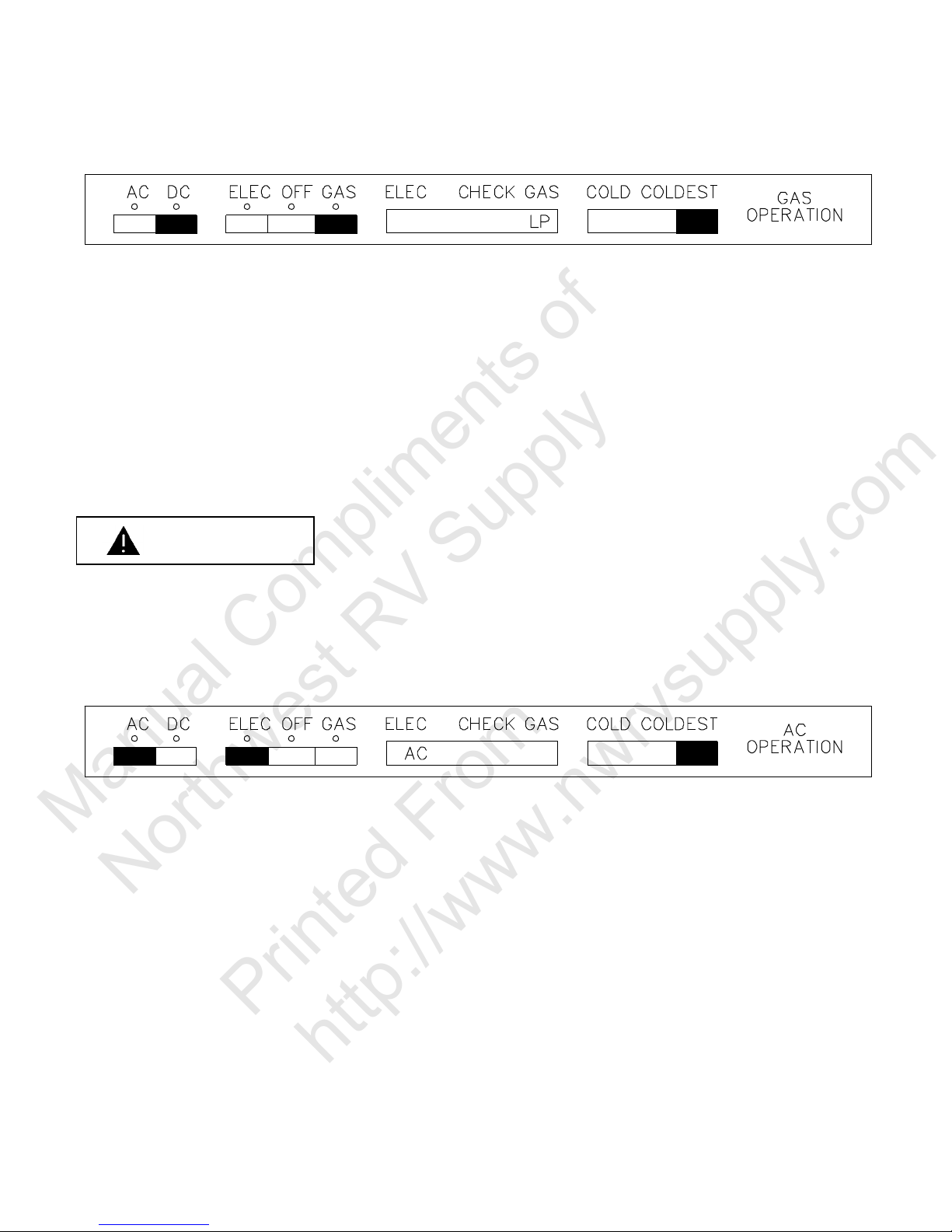
Figure 5.3
Manual Compliments of
Northwest RV Supply
Printed From
http://www.nwrvsupply.com
Figure 5.4
5-5

Figure 5.5
Manual Compliments of
Northwest RV Supply
Printed From
http://www.nwrvsupply.com
Figure 5.6
IMPORTANT INFORMATION ON 12 VOLT DC
OPERATION (3-Way
models Only)
The 12 volt DC mode is not designed for continuous DC operation - only for short "intransit" periods when gas or AC sources are
not available.
The 12 volt DC mode cannot be
used for the initial pull-down of the
refrigerator compartment(s). The
initial cooling operation must be
done in either the GAS or AC
modes. The refrigerator must be
cooled and stabilized before the
DC operation is effective.
tial when operating on DC. This
Good battery condition is essen-
implies an adequate recharging means which can handle the demands of
the refrigerator along with other loads.
The wires from the battery to the refrigerator must be of large enough size to
handle the load. The connections must be clean, tight and free from corrosion.
If not, a resulting voltage drop will cause a decreased cooling capacity.
The following points regarding the DC operation should be considered:
a. Operate the refrigerator in the DC mode only in periods when AC or
GAS operation is unavailable.
b. The DC operation is designed to operate during a short "hold over" pe-
riod, such as a four (4) to six (6) hour period while in transit. The refrigerator should not be switched to the DC mode if the food is not completely chilled.
c. Good battery condition is essential when operating on DC. This implies
an adequate recharging means which can handle the demands of the
refrigerator along with other loads.
d. The wire from the battery to the refrigerator must be of large enough
size to handle the load. The connections must be clean, tight and free
from corrosion. If not, a resulting voltage drop will cause a decreased
cooling capacity.
5-6
Location of Controls
Manual Compliments of
Northwest RV Supply
Printed From
http://www.nwrvsupply.com
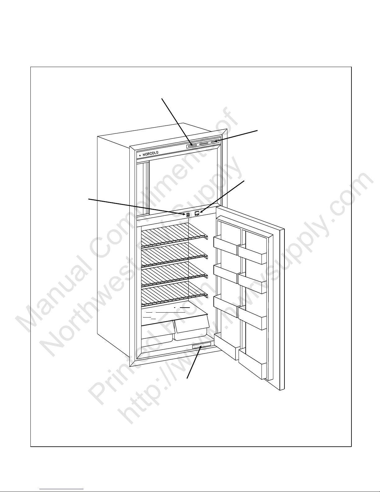
Models 865, 866, 868
Figure 5.7 Front View - Typical 2 Door Model
5-7
High Humidity Switch and
Manual Compliments of
Northwest RV Supply
Printed From
http://www.nwrvsupply.com
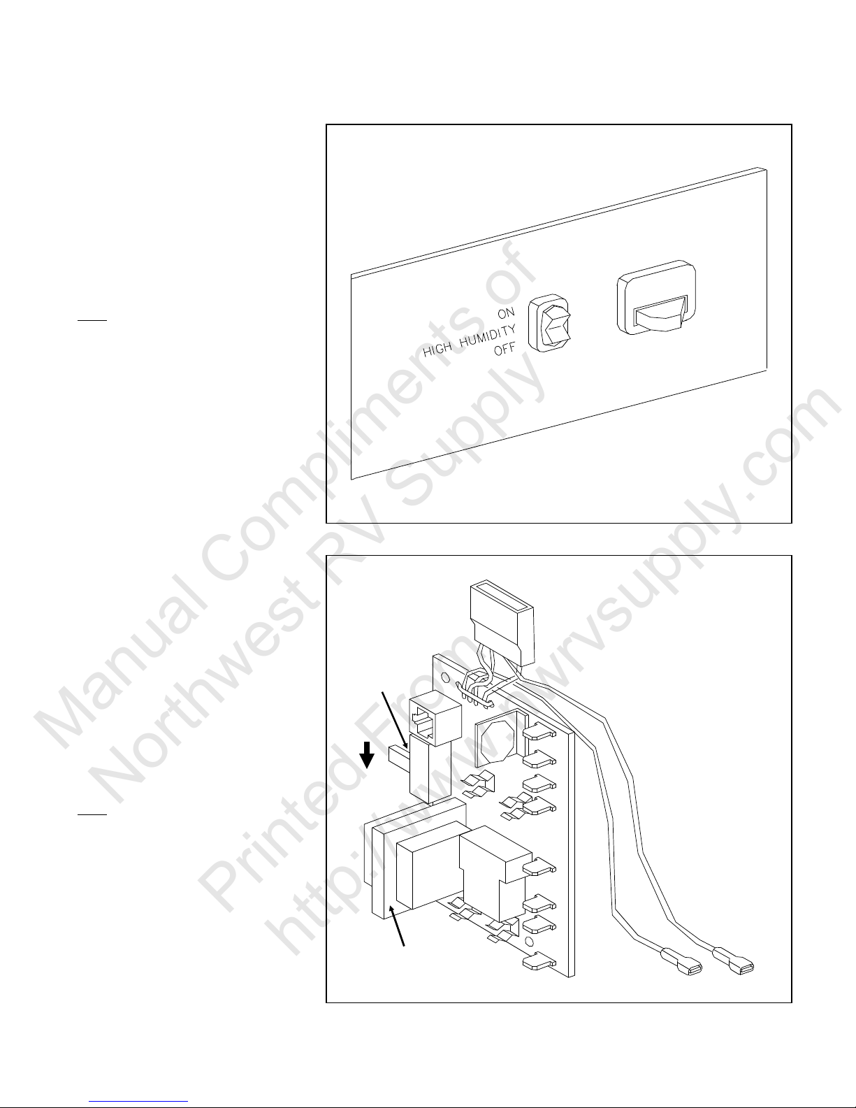
Interior Light Switch
Turning the HIGH HUMIDITY
switch to ON will keep the surface
between the door openings dry
during high humidity conditions.
The switch should be left in OFF
position unless condensation is
observed in this area.
Note:
During times when the refrigerator is not in use (storage) the
HIGH HUMIDITY switch must be
in the OFF position. If the switch
remains in the ON position, a continuous amp draw may occur, and
result in battery run down.
The interior light switch turns on
the light when the door is opened
(two door models only) See section about power supplies.
Parts and Their Function
Figure 5.8 Light, Humidity Switch
Power Supply Board
There are three versions of the
Power Supply board
1. The original version Power Supply board had a storage switch
located on the left side of the
board. The storage switch eliminates all 12 volt DC to the refrigerator when in OFF (up) position. A transformer was on the
board which allowed the refrigerator to operate on AC without
12 volt DC being applied.
Note:
On refrigerators with the "original
version" Power Supply board, the
storage switch must be in the ON
(down) position in order to allow
the refrigerator to operate in the
GAS or DC mode and to allow the
interior light and HIGH HUMIDITY
circuit to operate. When the storage switch is in the OFF (up) position the refrigerator will operate in
the AC electric mode, but not Gas
or DC Modes.
Figure 5.9 Power Supply Board - Original Version
5-8
See the identification of Power
Manual Compliments of
Northwest RV Supply
Printed From
http://www.nwrvsupply.com
Supply versions below.
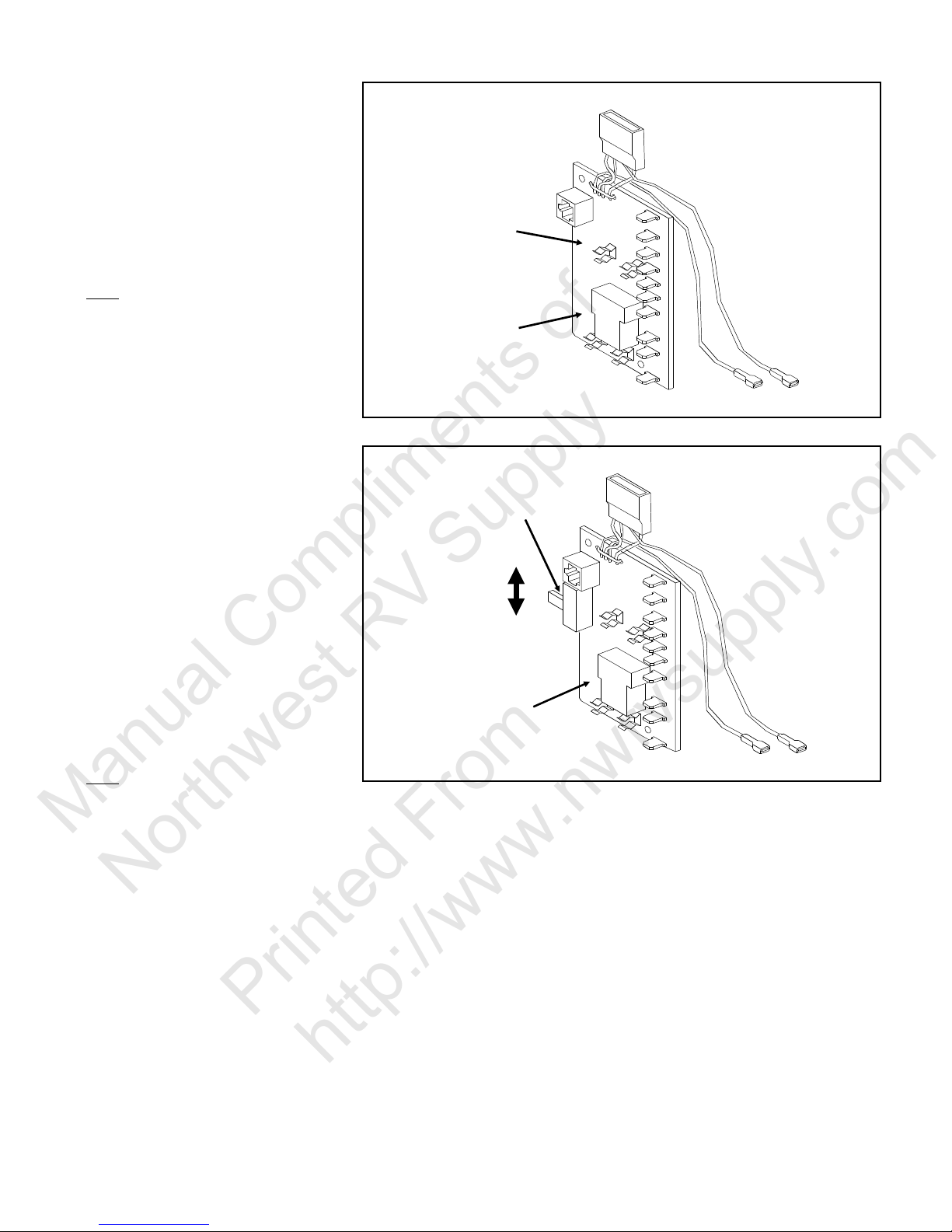
2. On the second version of the
Power Supply board, the storage switch and the transformer were removed. When
this occurred, a 12 Volt DC
supply was required for operation in all modes.
Note:
On refrigerators with the "second
version" Power Supply board, the
12 volt DC must be disconnected
from the Power Supply board to
eliminate a constant current draw
of 15 to 20 milliamps. Failure to
disconnect the 12 volt DC, (during
times which refrigerator is not in
use (storage), can cause battery
run down.
See the identification of Power
Supply versions below.
Figure 5.10 Power Supply Board - Second Version
3. On the third version of the
Power Supply board 12 volt
DC must be supplied in order
for the refrigerator to operate
in any mode. The "storage
switch" was added back to the
board but the switch itself will
not totally eliminate the 12 volt
DC to the refrigerator when in
the OFF (up) position.
Note:
The storage switch will eliminate
current to the interior light and
HIGH HUMIDITY circuit only. To
eliminate current draw, turn the
storage switch and the Mode Selector switch to the OFF position.
For added protection against battery run down, disconnect the 12
volt DC from the Power Supply
board.
See the identification of Power
Supply versions below.
Figure 5.11 Power Supply Board - Third Version
Power Supply Versions by Model & Serial Number
5-9
Power Supply Board Function
Manual Compliments of
Northwest RV Supply
Printed From
http://www.nwrvsupply.com
In response to the Mode Selection
at the Eyebrow, the Power Supply
outputs power to operate the refrigerator in the proper mode:
1. 12 volts DC to the Eyebrow
board through the cable.
2. 12 volts DC to the Ignition
Module when LP is selected.
3. 12 volts DC to the DC heater
(3 way only) when DC is selected.
4. 12 volts DC to the interior light
and High Humidity heater.
5. 120 volts to the AC heater
when AC is selected.
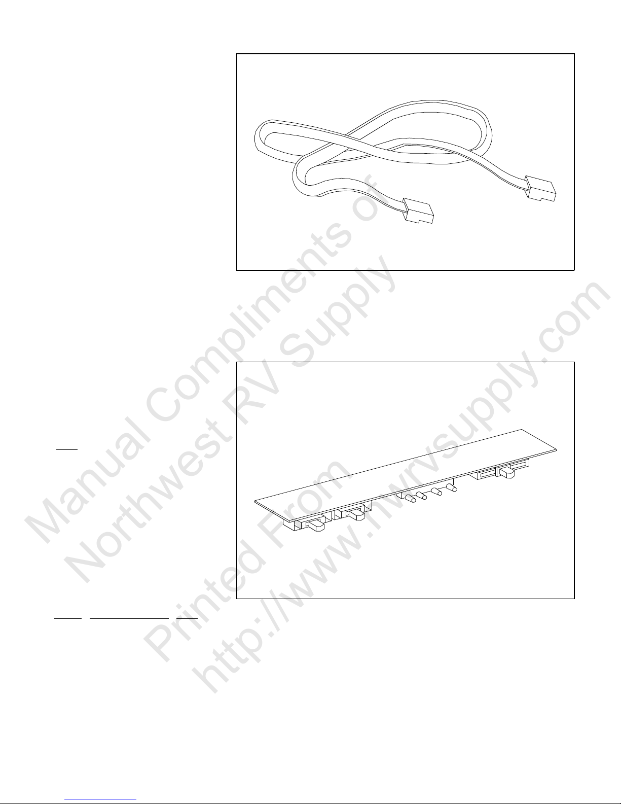
Cable
Connects the Power Supply to
the Eyebrow Board.
Eyebrow Board
Selects the mode of operation
(owners choice), indicates the
mode of operation determines the
operating temperature, and indicates when a trial for ignition fails.
Note:
On some Eyebrow Boards, the
AC Indicator light will illuminate
even though AC is not connected.
However, the refrigerator cannot
cool in this mode without AC being
connected. Also, a red light may
be visible at times through the
Thermostat slide opening; this light
is for Production testing only. This
information applies to the following
models: Use this information as a
guide.
Model Beginning Serial# Date
8652 001201 10-02-87
8653 001098 9-23-87
8662 012093 8-25-87
8663 008090 8-26-87
8682 008380 8-27-87
8683 009061 8-25-87
Figure 5.12 Cable
Figure 5.13 Eyebrow Board
5-10
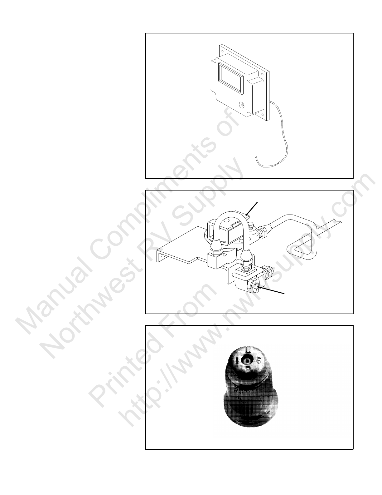
Ignition Module
Manual Compliments of
Northwest RV Supply
Printed From
http://www.nwrvsupply.com
Used only during GAS operation,
and does the following:
1. Supplies 12 volt DC to open
the gas valve.
2. Supplies power to the Ignition
electrode to ignite the Burner.
3. Senses the flame through the
Sense electrode.
4. When the Burner ignites and
stays lit, the Ignition Module
turns off the spark.
5. When the Burner does not ignite, or it ignites and goes out
when the sparking stops, the
Ignition Module will close the
gas valve, turning off the gas
supply to the Burner, and illuminate the red CHECK light.
Figure 5.14 Ignition Module
Gas Valve Assembly
The gas solenoid valve opens
when 12 volts is supplied and
closes when the 12 volts is removed. When it is open LP gas
will flow to the Burner.
The manual shut-off valve allows
the gas supply to be turned off to
the refrigerator.
Figure 5.15 Gas Valve Assembly
Orifice
Applies the correct amount of LP
gas to the Burner provided the
main line pressure is correct.
Figure 5.16 Burner Orifice
5-11
Burner
Manual Compliments of
Northwest RV Supply
Printed From
http://www.nwrvsupply.com
Applies heat to the cooling unit
when it has the correct amount of
LP gas and air.
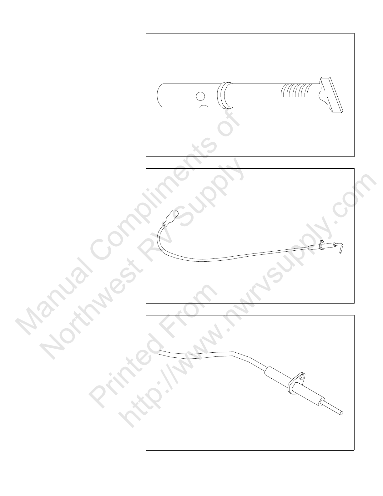
Ignition Electrode
Sparks the Burner to ignite the
flame when supplied with energy
from the Ignition Module.
Figure 5.17 Burner
Figure 5.18 Ignition Electrode
Sense Electrode
Senses the heat of the flame and
tells the Ignition Module if a flame
is present or not.
Figure 5.19 Sense Electrode
5-12
 Loading...