

Installation Instructions and
q
g
g
g
g
g
g
y
(
y
Users’ Operating Guide
Model 3163
WARNING
Improper installation, adjustment, alteration, service, or maintenance can
cause injury or property damage. Refer
to this manual. For assistance or additional information consult a qualified
installer, service agency, or the gas
supplier.
FOR YOUR SAFETY
If you smell gas:
1. Open windows
2. Do not touch any electrical
switches
3. Extinguish any open flame
4. Immediately call your gas supplier
FOR YOUR SAFETY
Do not store or use gasoline or other
flammable vapors and liquid in the vicinity of this or any other appliance.
Contents
Safety Precautions . . . . . . . . . . . . . . . 1
General Information . . . . . . . . . . . . . . . 2
Installation Instructions . . . . . . . . . . . . . 3
Direct Vent Re
Propane Gas Pressure and Connection . . . . 5
Electrical Connections . . . . . . . . . . . . . 5
Li
hting and Start-Up Instructions . . . . . . . 7
About Your Refri
Refri
erator Care . . . . . . . . . . . . . . . . 9
Refri
erator Servicing Requirements . . . . . . 9
Failure of Refri
Information About LP Gas . . . . . . . . . . 11
Diagrams . . . . . . . . . . . . . . . 12
Wirin
Warrant
uirements . . . . . . . . . . . . 3
erator . . . . . . . . . . . . . 8
eration . . . . . . . . . . . . 11
. . . . . . . . . . . . . . . . . . . 14
Specifications
LP Gas Operation - Specified Fuel: Propane; Gas Supply Pressure: 11" W.C.;
12 volt DC: 15.4 volts max. 10.5 volts min.
120 Volts AC Operation - 132 volts AC max. 108 volts min. 60 Hz.;
AC current draw: 1.3 amps @ 110 volts AC - 1.4 amps @ 120 volts AC
12 Volts DC Operation - 15.4 volts max. - 11.5 volts min.; DC current draw: 11.7 amps @
12 volts DC - 13.6 amps @ 14 volts DC
Operation where these specifications are exceeded ma
Model No.: _____________________ Serial No.: _____________________
Part No.: 617950 H (97 -0 1)
cause damage and will void the warranty.
for flame ignition and ventilation fan).
Safety Precautions
Read this manual and become thoroughly acquainted with it before installing or starting the
refrigerator. The following safety precautions and recommendations contained herein are for
your protection.
Improper installation, adjustment, or operation can cause injury or property damage.
The safety symbols used in this manual contain Safety Alert information. Understand their
meanings and be safety conscious.
DANGER
WARNING
CAUTION
Indicates the presence of a hazard that
injury, death, or substantial property damage if ignored.
Indicates the presence of a hazard that
sonal injury, death, or substantial property damage if ignored.
Indicates the presence of a hazard that
personal injury or substantial property damage if ignored.
cause severe pers onal
will
cause severe per-
can
will
or
cause a minor
can
General
•
Keep the refrigerator and surrounding area clean. Never use the area behind the refrigerator for storage; in particular, storing flammable materials (oily rags, paper, aerosol
cans, and chemicals.). Stored materials not only present a safety hazard but could block
the ventilation to the cooling unit.
•
Provide appropriate fire extinguishers installed in convenient locations. Consult your
local fire department for the correct type to use. Do not use foam or water on electrical
fires. Use an extinguisher rated by NFPA.
•
Make sure all fasteners, supports, seals, electrical covers are secure.
LP Gas System
•
LP gas is highly flammable. Gas connections must be leak tight. Do not smoke, create
sparks or use an open flame when checking gas connections. Do not ignore the "rotten
egg" smell of gas fumes.
•
Protect all gas lines from physical damage, vibration, or excessive heat.
•
Insure that the supply gas pressure is within the tolerance specified on the front cover
of this manual. The gas controls are designed for safety. Never tamper with the adjustment or function of the controls other than as directed by the Lighting and Shutdown
Instructions. All repairs must be done by a qualified service person.
Exhaust Gases
•
Proper ventilation to remove exhaust gases is extremely important. These gases, generated in the GAS mode at the left side and top of the refrigerator, replace the oxygen in
the air and in extreme cases can produce dangerous levels of carbon monoxide. This
manual contains installation instructions to safely remove the exhaust gases and seal
the zone from the living area. The installation instructions are certified by American Gas
Association and Canadian Gas Association and must be followed.
•
Check the burner for proper flame characteristics at the initial start-up and at least twice
every year. The information for this check is located in this manual and must be
performed by a qualified service person.
1
g
g
g
y
g
y
g
y by
y
g
Safety Precautions -
continued
Electrical Circuits - AC and DC
•
The 120 volt AC circuit must be properly grounded. Never cut or remove the round
grounding p rong from the refr iger ator ’s AC cor d. D o not use a two-pr ong ad apter . Do
not use an extension cord to connect to the approved AC receptacle.
•
Protect all wiring from physical damage, vibration, or excessive heat.
•
Always disconnect both AC and DC sources of power when working on either circuit
(This should be done only by a qualified service person).
•
Insure all terminating connections are clean and tight to prevent arcing or overheating.
•
Never allow Leak Detecting fluids or any other liquids to spill on electrical connections.
Many liquids are electrically conductive and could cause serious arcing damage and, in
some cases, fires.
Refrigerant System (Cooling Unit)
•
Never physically bend, drop, drill, weld, or hammer the cooling unit. Doing so could
cause the cooling unit to rupture and release dangerous chemicals which can cause
severe burns to the eyes or skin. If ignited, these chemicals will burn with intense flame.
A leaking cooling unit can release certain chromium compounds which, if inhaled , may
cause cancer.
•
Never apply direct heat in excess of 240° F to the cooling unit. Because the refrigerant
is hermetically sealed under pressure, a temperature sensitive safety device opens to
protect the cooling unit from erupting under excessive pressure. However, the expelled
refrigerant could ignite and burn if an ignition source were near.
•
Never attempt to repair or recharge the cooling unit. If defective, it must be replaced.
Child Entrapment
•
Never install door locks or other restraints which could entrap small children within the
refrigerator. The Travel Latch system must not be modified.
Handling the Refrigerator
•
Never lift the refrigerator without assistance. Protect yourself from body strain.
•
Avoid hot surfaces at the rear of the refrigerator when operating. The absorption type
refrigerator produces several hot areas at the rear of the unit. This is true whether in
GAS or ELECTRIC mode.
•
Take care to avoid brushing against the irregular shapes and sheet metal parts at the
rear of the refrigerator. Cuts or abrasions could result.
WARNING
This refrigerator is not intended to be operated as a free
standing unit (i.e. where the products of combustion
are
not isolated from the living area) or to be installed in
such a way as to conflict with these installation instructions. Unapproved installations can result in personal
injury or property damage.
General Information
The model 3163 is designed for built-in installation and
operates on pr opane
The propane
combustion unit. A sealed combustion i nstal lati on util izes a sin
fresh air to the burner and to remove the products
pl
of combustion. This insures the products of combustion
are isolated from the livin
vent-air intake/exhaust assembl
vehicle’s outside wall and is connected to the refri
tor’s burner assembl
The vent-air intake/exhaust assembl
installation has been certified for this refri
must not
le vent-air intake/exhaust assembly to sup-
be modified.
as, 110 volts AC or 12 volts DC.
as mode of operation is that of a sealed
area of the vehicle. The
is routed through the
era-
flexible piping.
used for this
erator and
2
Installation Instructions
y
y
g
y
y
g
y
g
y
g
q
q
g
q
q
q
g
y
g
g
y
g
g
g
y
g
g
q
g
q
q
g
g
q
g
g
WARNING
Improper location, installation, adjustment, alteration,
or modifications can cause injury or property damage.
Refer to this manual for proper instructions. For assistance or additional information consult a qualified i nstaller, service agency, or Norcold.
Requirements
Installation must be made in accordance with these
installation instructions for the Norcold factor
to be in effect.
This appliance is desi
edition of ANSI Z21.19 standards b
Association and is approved b
Association.
Installation must conform with local codes or, in the
absence of local codes with the followin
applicable.
In the United States:
a. National Fuel Gas Code, ANSI Z223.1.
b. Manufactured Home Construction and Safet
Standard, Title 24 CFR, Part 32-80.
c.Standard for Recreational Vehicles, ANSI
A119.2.
When an external electrical source is utilized, the
erator, when installed, must be electricall
refri
rounded in accordance with local codes or, in the
absence of local codes, the National Electrical Code,
ANSI/NFPA 70.
In Canada:
a. Current CGA B149.1 and 2 installation code for
Propane Appliances and E
b. Current CSA Z240.4 Gas E
tional Vehi c l e s an d M ob i le Housin
rent CSA Z240.4.2 Installation Re
Propane Appliances an d E
n certified under the latest
the American Gas
the Canadian Gas
uipment.
uipped Recrea-
uipment in Recrea -
warrant
Standards as
or the cur-
uirement for
tional Vehicles.
c. Current CSA Z240.6.2/C22.2 No. 148 Electrical
uirement for Recreational Vehicles.
Re
When installed, the refri
rounded in accordance with current Canadian Electri-
cal Code C22.2 Parts 1 and 2.
erator must be electricall
Refrigerator Enclosure Dimensions
The following dimensions will allow the installation
and removal of the refri
provide the necessar
around the refri
Refrigerator Enclosure Cut-Out Dimensions
Hei
24 1/8" 25 5/8" 16 7/8"
The refri
floor awa
must be stron
of the refri
erator cooling system.
ht Width Depth
erator must be placed on a solid and level
from heat generating sources. The floor
enough to support the combined weight
erator and food.
erator. Also, the dimensions
clearances for air circulation
Notice: Never install the r efrigerator direc tly on car-
peting. To pro tect carpeting, the refrigerator
must be placed on a metal or wood panel
extending at least th e full width an d depth of
the refrigerator.
WARNING
Hazardous vapors! The burner or spark from the refrigerator’s ignitor can ignite vapors causing fi re or expl osion resulting in property damage, serious personal
injury or loss of life. Never store gasoline, combustible
materials and other flammable vapors and liquids in the
vicinity of the refrigerator.
Direct Vent Requirements
Interior Ventilation
An inlet and exhaust vent is required to insure adeuate air flow. The refrigerator is equipped with an inlet
uare inches
erator. The
vent located at the bottom front of the refri
installer is re
must have a cross sectional area of 30 s
minimum. The exhaust vent is to be installed above the
top surface of the refri
enerated by the cooling unit. The refrigerator is
uipped with a DC ventilation fan to assist the air flow
e
across the refri
the refrigerator in the Gas mode.
uired to provide the exhaust vent which
erator so as not to trap hot air
erator’s cooling system while operatin
Installing the Vent-Air Intake/Exhaust Assy.
WARNING
Improper location and installation can cause injury or
property damage. This refrigerator and it’s vents are
design certified by the American Gas Assoc iation and
the Canadian Gas Association. Any dev iation or substitution will void the agencies’ certifications and the
Norcold warranty. Refer to this manual for proper instructions. Install the refrigerator and vents as directed
by Norcold without modification.
3
The clearance from the refrigerator’s left side (facin
g
g
g
g
g
g
g
g
g
g
g
g
(
g
y
y
g
g
g
g
g
g
g
the front of the refrigerator) to the vehicles exterior wall
is important. This is the area in which the inlet and outlet
flexible pipin
housin
to access
for visual check of the burner flame.
will be connected to the vent terminal
during installation. Provisions must be made
as burner observation port for service and
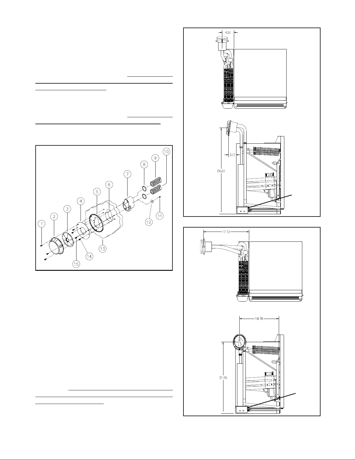
Refer to Figures 3
and 4 for maximum clearances from refrigerator cabi net to vehicles exterior wall.
The wall thickness the vent terminal housing will
accommodate is .030" minimum to 1.250" maximum.
ure 2 below illustrates the configuration of the open-
Fi
for the vent terminal housing.
in
opening in the vehicle wall larger than requir ed.
clearance should be enou
pass throu
the outer
h the opening. If the opening is too large,
asket will not cover the vent housing opening.
h for the terminal housing to
Do not make the
The
Burner
Observation
Port
Figure 2 Air Intake/Exhaust Assembl
1. Mountin
Screw 8. O Rings
2. Vent Cover 9. Intake Pipin
3. Outer Disk 10. Exhaust Pipin
4. Inner Disk 11. Locking Washer Screw
5. Rubber Gasket 12. Lockin
Washer
6. Vent Terminal 13. Vehicle Exterior Wall
Housin
7. Vent Terminal 15. Mountin
Cut-Out 14. Mounting Screw
Screw
Housin
It is imperative that the wall openin
terminal housin
not be too low. The flexible pipin
for the vent
inlet and outlet pipes) must rise from the refrigerator to
the terminal housin
intake assembl
installations.
Figures 3 and 4 illustrate two installations
. There are two specific vent-air
kits available to accommodate most
with the maximum flexible piping lengths and the vent
terminal housing locations.
Figure 3-Kit# 617941 Flexible Pipe and Vent Location
Burner
Observation
Port
Figure 4-Kit# 617943 Flexible Pipe and Vent Location
4

Propane Gas Pressure and Connection
g
g
g
y
g
g ty
g
g
g
g
g
g
y
y
g
g
(
g
g
g
y
g
g
g g
y
g
g
g
y
y (
y sy
y
g
(+)
g
g
g
g
g
g
y
y
WARNING
Hazardous vapors! Propane gas can cause an explosion and result in property damage, personal inj ury or
death. Use extreme care when working with or near a
propane system. Do not smoke. Do not create sparks
or use an open flame to check supply piping and fittings
for leaks.
This refrigerator is designed to operate on propane
as with a supply pressure to the refrigerator of 11
inches water column. A pressure re
between the refri
maintain the suppl
Do not connect the refrigerator directly to the main
umn.
erator and the main gas tank to
pressure of 11 inches water col-
ulator is required
tank without a pressure regulator in line.
Use supply piping and fittings that comply with NFPA
501C, as well as local, s tate, and national codes
ernin
routin
3/8" diameter copper pipin
of sufficient diameter to prevent gas pressure loss to
the refri
of the refri
flare connection.
The
the possibilit
piping should enter at the vicinity of the gas connection
located at the top of the refri
which the
approximately 1/2" diameter) to provide adequate
clearance. Once the
sealant around the pipin
mize abrasion, vibration, and to serve as a barrier from
external moisture.
To prevent
piping, use two wrenches, one to hold the fitting of the
manual
to the refrigerator.
pe and size. Also, refer to NFPA 501C for
and testing. The gas should be supplied by a
or other approved pipin
erator. The gas connection located at the top
erator is a 3/8 inch SAE (UNF 5/8"-18) male
as piping should be routed in a manner to limit
of vibration and abrasion. The gas suppl
erator. The hole through
as piping enters should be of sufficient size
as piping is installed, apply a
at its point of entry to mini-
as leaks and damage to the gas suppl
as valve the other to tighten the supply pipin
ov-
Electrical Connections
It is the owners/installers personal responsibility and
obligation to provide a properly grounded circuit to the
refrigerator in accordance with local codes or, in the
absence of local codes, the National Electrical Code,
ANSI/NFPA 70. Do not cut or remove the grounding
prong from the refrigerator’s AC power cord. Do not use
a two-prong adapter or extension cord.
The free length of the AC power cord is 36 inc hes. It
is recommended that the three-pron
tacle be located within reach of the cord. The cord must
be routed so as not to come in contact with the burner,
flue pipe, or an
dama
e to the cord insulation.
other component that could cause
rounded recep-
12 Volt DC Connection
12 volts DC is required for flame ignition and the
mechanical fan in the
heater in the DC mode. The refri
power source from the vehicle’s 12 volt s
an auxiliar
batter
supplies power to other DC components of the vehicle.
The DC suppl
terminal block located at the top of the refri
lead is marked positive
ative (-). Correct polarity must be observed when
ne
connectin
house) battery or the engine battery. The
stem not only supplies the refrigerator, but also
the DC supply.
as mode and to power the DC
erator receives its DC
stem; either
connects to the refrigerator at the
erator. One
and the other is marked
Do not use the chassis or
vehicle frame as one of the conductors. Connect supply
wires at the battery and route to the refrigerator.
The distance the current travels from the battery to the
erator dictates the AWG wire size to be used.
refri
Undersized wire for the distance can result in a volta
drop. A volta
the DC heater and resultant refri
e drop will affect the wattage output of
erator performance.
WARNING
Use of undersized wire and/or inadequate fuses can
result in an electrical fire in the event of a circuit
overload. To prevent a possible elec trical fire, follow
Norcold’s wire and fuse size requirements, or any
applicable state and local codes.
e
120 Volts AC
WARNING
This refrigerator is designed to operate on a 120 volt
AC, 60 Hertz grounded circuit. The refrigerator AC
power cord is equipped with a three-prong grounding
It is recommended to install a fuse between the batter
and the refrigerator to protect the supply wiring. For
optimum protection, install the fuse as close to the
batter
as possible.
Recommended wire and fuse size:
minimum wire
size
maximum fuse
size
plug which must mate with a three-prong grounding receptacle to pr ote ct ag ain st pos sibl e sh ock ha zar ds. Op erating the refrigerator without proper ground can cause
0 - 20’ 12 AWG 20 Amp
over 20’ 10 AWG 30 Amp
pro pe r ty da mage, severe personal in jury or loss of life.
5

When a wire size is installed whic h is larger than the
q
g
g
y
j
g
g
y
y
g
g
g
g
g
g
g
g
g
j
y
g
g
g
g
g
g
g
y
g
g
y
g
g
g
g
g
g
g
y
y
g
g (
g
g
g (
g
y
g
q
)
g
g
g
y
(
y
g
g
g
y
)
g
g
g
g
y
minimum size indicated above, the wire must be fused
in accordance with the re
A119.2 Standards or local
uirements of the R.V.I.A.
overning codes.
Exhaust Pipe - This pipe is insulated and connects to
the flue tube of the coolin
and connect to the bottom openin
the vent terminal housin
unit. Route
of
.
Reversing Door Swing
Your refrigerator is equipped with convertible door
es. The hinging of the door can be changed to the
hin
opposite side an
1. Remove all items of food,
door.
2. Usin
hin
e pin.
3. Remove the travel latch b
4. Remove the door b
the top of the door away from the refrigerator. Lift
the door up and off the lower hin
5. Remove the lower hin
6. Usin
latch bracket.
7. Remove the bottom hin
to the location where the travel latch bracket was
removed.
8. Remove the top hin
tom on the opposite side.
9. Mount the travel latch bracket to the opposite
side from which it was removed.
10. Replace the bottom hin
cate the bottom of the door on the hin
close door.
11. Replace the top hin
12. Replace travel latch in door.
13. Open and close the door several times to insure
proper door seal. Ad
accomplished b
and repositionin
time you wish.
uices, etc., from the
a slotted screwdriver, remove the top
lifting out of the door.
opening slightly and pullin
e pin.
e pin.
a Phillips screwdriver, remove the travel
e bracket and reposition
e and reposition at the bot-
e pin bracket and relo-
e pin and
e pin.
ustments, if needed, can be
loosening both hinge brackets
.
Insulating the Flexible Exhaust Piping
The flexible exhaust pipe must be insulated pri or to
installation into the vent terminal housi n
exhaust pipe connects to the flue tube of the refri
tors coolin
the vent terminal housin
insulation material supplied with the vent-air intake/exhaust kit.
unit and routes to the bottom opening of
. Use the non-combustible
Do not insulate the Air Intake pipe.
. The flexible
era-
Installing Refrigerator into the Enclosure
Set refrigerator into enclosure and slide it back
h to connect gas supply piping to manual shut-off
enou
valve located at top of the refri
DC suppl
refri
Place the "O" rin
Bend flexible pipes so the
Connect pipin
to terminal block also located at top of
erator. Connect AC power cord to receptacle.
s onto ends of both flexible pipes.
as follows:
erator. Connect 12 volt
clear top of enclosure
Intake Pipe - This pipe is
to the burner c ove r . Ro ut e an d c on nec t
to the top openi n
housin
Secure both flexible pipes to vent terminal housin
with locking washer and screw. Slide refrigerator com-
into enclosure.
pletel
not
insulated an d c on ne c ts
of the vent te rminal
.
Testing of the Vehicle’s Gas Supply Piping
When installation is complete, the propane gas
piping must be inspected an d test ed for leaks
suppl
from the refri
a leak detection solution.
erator to the main gas supply tank. Use
Do not test for leaks with an
open flame.
If compressed air is used for leak testing, the pressure
must not exceed 1/2 psi
The appliance and its individual shutoff valve must be
disconnected from the
any pressure testing of that system at test pressure in
excess of 1/2 psi
The appliance must be isolated from the
piping system by closing its manual shutoff valve durin
any pressure testing of the gas supply piping system at
test pressure less than or e
water column
Check the
other
not exceed 11 inches water column. With other appliances operatin
10.5 inches water column.
as appliances operating. The pressure should
14 inches water column).
.
as pressure to the refrigerator without
the pressure should not be less than
14 inches water column).
as supply piping system durin
as suppl
ual to 1/2 psig (14 inches
Check Out of Flame Failure Safety Device
1. To verify operation of the flame failure safet
device, start the refrigerator in the gas mode
refer to lighting instructions on page 8) and verif
the presence of a flame.
2. Turn off the
at the main
3. The flame will
flame safet
audible click will be heard as this device closes
4. Turn the
5. Attempt to li
selection button to the
the safety valve.
6. Without holding the safety valve in, the burner
flame will not re-li
failure safet
7.
as at the manual shut-off valve or
as supply tank.
o out and within 3 minutes the
device will automatically close (an
as on at the manual shut-off valve.
ht the burner by placing the mode
as mode.
ht. This indicates the flame
device is functioning.
Do not push in
.
6

Securing the Refrigerator
y
g
g
y
y
g
g
g
y
g
g
g g
y
g
g
g
g
g
g
(
)
g
g
g
(
)
y
g
g
g
g
(E)
y
(G) g
y
y g
(D) 12 Volts DC Operation
The refrigerator can be secured into the enclosure b
screws through the mounting holes provided at the front
of the refri
movin
erator. This will prevent the refrigerator from
in transit.
Hypot Tests
A Dielectric Strength test (Hypot) has been conducted
at the factor
additional test. If H
the 12 volt circuit, the 12 volts must be di sconnected
from the refri
and the refrigerator does not require an
pot tests are to be conducted on
erator to protect the flame ignition circuit.
Location of Operating Controls
The refrigerators operating controls are located in a
cluster above the refri
erator door.
Description of Controls
A B
C
G
Pressing button (D) selects DC mode of operation.
When DC is selected and DC is available to refri
the refri
DC operation is a continuous run
trol
erator will operate at full cooling power. The
no thermostat con-
mode.
erator,
(E) Gas Operation
Pressing button (E) selects Gas mode of operation.
The refri
When
is ener
Note: Push safety valve button in and hold until
flame is present at burner
until a flame is present at burner. When a flame is
sensed b
sparkin
nates indicatin
erator is equipped with electronic ignition.
as mode is selected, the electronic ignition
ized and sparking is generated at burner
. Sparking will continue
the electronic ignition module, the
ceases and flame indicator (G) illumi-
refrigerator is operating on gas.
(F) Off
Pressing button (F) will interrupt all power sources and
cease operation of refri
erator.
Lighting and Start-Up Instructions
Figure 5
DEF
(A) Safety Valve
The safety valve is designed so that any loss of
flame will stop
means of a thermocoup le that is positio ne d in the
b
flame. As l on
ple, the valve will remain open. Upon flame failure,
the valve closes, shuttin
Durin
must be held in until a flame is established at burner.
as ignition pro cess, t he safe ty valve button
as flow to th e b urn er . It i s co nt rol l e d
as a flame is det ec t ed by thermocou-
off gas flow to burner.
(B) Thermostat
The thermostat controls both the gas and the AC
electric operations, thereb
resettin
lected. Rotate the thermostat knob clockwise to make
refri
each time a different power source is se-
erator cabinet colder.
eliminating the necessity of
(C) 120 Volts AC Operation
Pressing button (C) selects AC mode of operation.
When AC mode is selected and AC volta
to refri
AC.
erator, the refrigerator will operate on 120 volts
e is supplied
The Lighting and Start-Up Instructions are located on
the top portion of the interior door liner.
Refer to Fi
ure 5 for location of the operating controls.
Notice: When warm humid weather conditions are ob-
served, operate the refrigerator on either AC or
DC electric for a minimum of five (5) minutes
before attempting to follow the Start-Up Instructions for Gas operation.
Gas Operation
WARNING
Do not hold gas valve in more than 30 seconds. If the
flame is not indicated within this time, press selector
switch (F), wait 2 minutes, and retry. Continuing to hold
the gas valve in will cause gas to build up in the burner
area and can result in an explosion which can c ause
property damage or severe personal injury.
1. Set thermostat (B) to the start setting.
2. Press mode selector button
will be present at the burner.
3. Push and hold the safet
the indicator lamp
to hold the safet
and then release. The indicator lamp should
remain a stead
2 minutes, repeat this step.
valve button in for 15 seco nds
low. If the lamp turns off, wait
valve button (A) until
lows steady. Continue
. Ignition spark
7

Notice: On initial start-up, i t may take longer for
(B)
g
j
y
(
)
g
g
y
y
y
g
g
g
g
g
y
g
g
g
)
y
y
g
y
g
g
g
ging
g
g
g
q
g
g
g
g
g
g
the burner to light because of air being
purged from the gas supply line.
Important Note: Altitude above 4000 feet affects the
performance of the gas burner, could reduce cooling performance of the refrigerator, and may cause
nuisance burner outages. Norcold recommends
that the refrigerator be switched to AC or DC electric at an altitude above 4000 feet. An optional high
altitude kit is available through your dealer for gas
operation at altitudes up to 10,000 feet.
4. Set thermostat to desired temperature setting.
Notice
Cleaning vehicle exterior by a power
:
(car) wash may allow water to enter
the refrigerator’s burner area through the
vent cap. Operate the refrigerator on
gas to ensure evaporation of any mositure that may have entered the burner
area.
Operation in Transit
While the refrigerator should be level when the vehicle
is stationar
affected.
, performance during transit is not normall
Ventilation Fan
A thermostat controlled mechanical fan is used to
move air across the refri
thermostat is calibrated to activ ate the fan whenever
the vehicle’s interior temperature reaches 85 de
or hi
her.
When leavin
to leave windows or roof exhaust vents open to maintain the vehicle’s interior temperature below 85 de-
rees. This will allow the refrigerator to op erate efficiently,
minimize fan operation, and limit current draw from the
.
batter
the vehicle unattended, it is advisable
erator’s cooling system. The
rees
Information Regarding Battery Drain
AC Operation
1. Press mode selection button (C).
2. Set the thermostat
Allow to operate at coldest settin
before ad
usting.
to the coldest setting.
for 6 to 8 hours
DC Operation
1. Press mode selection button (D). There is no
need to set thermostat to an
operation is a continuous run
control
mode.
setting. The DC
no thermostat
Shut-Down: All Modes
1. Place the mode selector button to the off position.
This will interrupt all AC and DC power and stop
operation of the refri
erator.
Users Operating Guide
This appliance has been designed for storage of
foods.
About Your Refrigerator
Storage Volume
1.8 cu. ft.
Leveling
The Norcold refrigerator does not require critical lev-
. Normal vehicle leveling to provide comfort for the
elin
vehicle occupants is sat isfactor
for refrigerator operation.
A 12 volt DC source is required for the gas and DC
modes of operation and the mechanical fan which
assists the air flow across the refri
system. For gas operation, the DC power source
supplies volta
and to the mechanical fan (240 milliamps). The current draw is 340 milliamps. This indicates that drain
on the batter
"batter
source supplies volta
ment. The DC operation draws approximatel
amps at 12 VDC and 13.6 amps at 14 VDC. It is
evident that current draw for DC operation is hi
therefore, the refri
lon
means of rechar
should be checked while operatin
the DC mode . The vo lta
never be below 11.5 volts DC.
run down". For DC operation, the DC power
periods of time from a battery only without a
e for electronic ignition (100 milliamps
is very low and has little effect on
e for the cartridge heating ele-
erator should not be operated for
the battery. The DC voltage
e at the refrigerator shou ld
erator’s coolin
11.7
h,
the refrigerator in
Fresh Food Compartment
This compartment is designed to store and cool foods.
eration requires air circulation within the fresh
Refri
food compartment. Restriction of air circulation will
cause inade
ble food spoila
with paper or plastic.
To prevent food odors, store highly flavored foods in
covered dishes, plastic ba
etables to retain crispness.
ve
To reduce frost formation on the coolin
and moist foods.
or let door remain open longer than necessary.
Allow the refrigerator to operate for a minimum of eight
hours or overni
food. Loadin
uate refrigerator temperatures and possi-
Do not cover the refrigerator shelf
e.
s or wrap in foil. Cover
fin, cover liquids
Do not put ho t foods into the refrigerator
ht before loading the refrigerator with
a warm refrigerator with warm foods will
8

require a longer period of time for the refrigerator
g
y
g
g
y
y
q
)
g
g
y
g
y
y
g
g
g
g
g
y
g
(
)
y
g
g
y
g
g
g
q
g
y
(
g
g
g
y
y
g
j
y
(
y
g
y
j
g
y
temperature to lower.
Refrigerator Care
Owner’s Check list
Your refrigerator is designed for years of trouble free
operation when a few simple steps are performed on a
schedule; three to six month intervals. Use the followin
as guide and a reminder.
Checking Door Seal
The door gasket must seal completely around entire
th of the door. This will insure cooling efficiency and
len
prevent frost formation. Fre
in
are indications of air leaks.
To check for proper door sea l, la
dollar bill) between the gasket and the refrigerator. Close
the door and with draw t he paper . A frict ional dr a
be observed. Re peat all around the door. I f the paper does
not have a noticeable frictional dra
sealin
. Contact your service agency for assistance.
uent frost or reduced cool-
a long strip of paper
should
, the gasket is not
1. Visual inspection of the vent-air intake assembl
to insure the vent is not obstructed and free of
debris.
2. Keep the internal vents unobstructed to insure
proper air circulation around refri
in
unit.
3. Insure
such as Butane or Butane mixtures.
4. Insure
5. Allow ade
before loading the refrigerator with foods.
6. Insure the refri
with paper or plastic.
our LP gas is propane, not other types
our 12 volt DC supply is properly charged.
uate time (6-8 hours or overnight
erator’s wire shelf is not covered
erator’s cool-
Defrosting the Refrigerator
After a period of operation, it is normal for frost to
radually accumulate on the cooling fins, eventuall
impairing cooling.
To defrost the r ef ri
to "Off" position. Empt
door open. When the frost has melted, wipe the
moisture with a clean dr
restart the refri
mum settin
mid-ran
for several hours before returning to the
e setting.
erator, place the mo de sele ctor
the refrigerator and leave the
cloth. Replace all foods and
erator. Set the thermostat to its maxi-
Cleaning the Interior of Refrigerator
It is important to keep the refrigerator interior clean to
minimize food odors. The best time to clean the refri
erator interior is after defrostin
of dishwater detergent to lukewarm water and wash the
erators interior.
refri
Do not use abrasive cleaners to
clean the interior of the refrigerator. Abrasive cleaners
can harm the refrigerators interior surface.
Rinsing the interior in a solution of baki ng soda and
a tablespoon of baking soda to a quart of water
water
will freshen and neutralize odors. Wipe refrigerator
interior with a soft dr
The door
as the refri
er of petroleum jelly to the gasket on the hinge side.
la
This will keep the
insurin
asket can be cleaned in the same manner
erator interior. After cleaning, apply a thin
a proper door seal.
cloth to prevent water spots.
asket soft and prevent it from rolling,
. Add a small quantit
Refrigerator Servicing Requirements
WARNING
Unauthorized or improper servicing of this refrigerator
can cause severe personal injury, property damage or
both. All required service and maintenance
performed by your dealer or a Norcold authorized service center. Norcold will not accept responsibility for
improper installation, adjustment, alteration, service or
maintenance performed by anyone other than a qualified dealer or a Norcold Service Center. Costs and
consequential problems resulting from unauthorized or
improper servicing of this refrigerator are the refrigerator owner’s responsibility.
Note: The refrigerator information packet supplied
with your refrigerator includes a Norcold Service Center location booklet.
Servicing Requirements Check list
In addition to the Check list items under refrigerator
care, a safe t
b
the followin
-
a qualified service facility. The schedule is to include
1. Check and ad
suppl
2. Inspection and leak test
suppl
3. Inspection of exhaust and intake pipin
vent-air intake assembl
tions to the burner and the vent.
4. Clean burner, burner orifice, and flue tube.
5. Check and ad
sure the thermocouple is clean and secure in the
burner bracket.
6. Inspection of the operatin
insure the
and performance schedule is to be made
:
ustment (twice a year) of gas
pressure.
twice a year) of gas
piping and fittings.
. Insure proper connec-
ust the ignition electrode gap. In-
controls and wiring to
are in good condition.
must be
of the
9

Gas Burner Flame
y
g
g
g
g
y
y
q
g
g
g
y
y
g
gly
q
g
g
g
g
g
g
g
y
y
y
g
y
g
g
g
g
y
g
g
g
g
g
g
g
g
g
g
y
g
g
g
g
y
The gas operation of your refrigerator is controlled b
the correct burner flame which supplies the heat input
to the refri
flame is dependent upon correct input
and the burner and burner orifice bein
propane
inspected and tested at least twice a
tions and tests must be performed b
supplier or a
A visual check of the burner flame should be made
ularly. The burner flame can be observed through
re
the observation port on the left side of the burner box.
erator’s cooling system. The correct burner
as pressure
clean. The
as piping and the supply pressure must be
ear. All inspec-
the propane gas
ualified service agency.
Orifice Adapter
Fittin
One-piece Assembl
Figure 8
WARNING
Press-fitted
Orifice
Burner
FLUE TUBE
PALE BLUE
OUTER CONE
SHARP BLUE
INNER CONE
BURNER
Figure 7
The flame should be sharp blue as illustrated in Fi
7 with a stable burnin
constant
ellow component observed or if the flame
appears erratic and unstable, contact
appearance. When there is a
our dealer, gas
ure
supplier, or a Norcold authorized s ervice center. Al so
observe the position of the flame; it must be centered
under the flue tube without touchin
the tube. Norcold stron
recommends that any re-
the inner wall of
uired adjustments be performed by your dealer or a
Norcold authorized service center.
Burner Orifice Removal and Cleaning
Procedure
1. Turn off the gas supply at the main tank.
2. Turn refri
3. Turn off refri
4. Remove refri
5. Remove the screw located on the ri
the burner box.
6. Remove the two screws securin
to the refri
7. Remove the burner box from the coolin
8. Remove the flare nut from the orifice assembl
9. Remove the orifice assembl
erator off.
erator’s manual shut-off valve.
erator from the enclosure.
ht front of
the heat shield
erator’s support brackets.
unit.
from the burner.
Do not attempt to remove the orifice from the orifice
adapter fitting when cleaning. Removing the orifice will
cause serious damage to the orifice and it’s press- fit
seal and may create propane gas leakage. Leaking
propane gas, if ignited, could cause an explosion resulting in severe personal injury or death.
10. Clean the orific e assembly with alcohol and air
pressure.
Do not clean the orifice with a pin or
similar object.
11. Clean the burner with alcohol and air pressure.
Make sure the slo ts of the burner are unobstructed.
12. Re-install the or ifice assembl
wrench ti
ht in burner.
. Insure orifice is
13. Reconnect flare nut to orifice assembl
14. Re-install the burner box. Ins ure the burner box
asket seal is in good condition before reinstall-
. If damaged, contact your dealer or a Norcold
in
Service Center.
15. Leak test refri
16. Re-install the refri
piping at the manual shut-off valve.
pl
erator fittings.
erator and leak test main sup-
Removing and Replacing the Refrigerator
To remove the refrigerator, interrupt both the AC
and DC power sources to the refri
the propane
screws at the front securin
enclosure. Slide the refri
disconnect
as at the main supply tank. Remove the
the refrigerator to the
erator forward enough to
as supply piping at the manual shutoff
valve locat ed at the top of the re fri
nect the 12 volts DC at the termin al block. Disconnect
the AC power cord fro m the r ece ptac le. Remove the
intake and exhaust pip in
. The refrigerator is now ready for removal. When
in
reinstallin
the refrigerator, make certain that the con-
from the vent terminal hous-
nections of the intake and exhaust pipin
sealed. If damage occurs to the "O" ring seals of the
.
flexible pipin
Center to obtain new "O" rin
check the
, contact your dealer or a Norcold Service
seals. After reinstalling,
as fitting connections for leaks.
check for leaks with an open flame.
erator. Turn of f
erator. Discon-
.
is properl
Do not
10

Failure of Refrigeration
g sy
g
g
g
g
g
g
y
g
g
(
g
y
y
y
y
y
g
g
g
g
y
y
y
g
g
gaug
g
g
(
y
g
j
g
y
j
y
y
y
g
y
g
g
g
y
g
g
y
y
y
y
Failure of refrigeration does not necessarily indicate
that the coolin
its operation must be checked.
ernin
If the refri
coolin
mode of operation. If the refri
in
erator has been switched from one power source to the
other allow several hours to assure the refri
c
failure in the electric or
coolin
unit. To determine the actual cause, contact your dealer
or a Norcold authorized service center.
is noticed, switch the refrigerator to the AC
on electric, switch to gas operation. After the refrig-
cling properly. This will determine if a component
fault. If no cooling is evident after eight hours
or overnight), the cause of failure may be the coolin
stem is defective. Other factors gov-
erator is operating on gas and loss of
erator has been operat-
erator is
as controls is causing the
Replacement Parts
The following is a list of parts which can be replaced
the owner and are obtainable by contacting a Nor-
b
cold Service Center.
Description Part Number
stem Cover - Taupe 617904
S
stem Cover - Gra
S
Thermostat Knob 617971
Door Gasket 617906
Travel Latch Assembl
Air Inlet Grille 617938
Owner’s Manual 617950
617905
617916
Information About LP Gas
WARNING
Hazardous vapors! Propane gas can cause an explosion and result in property damage, sever personal
injury, or loss of life. Use extreme care when working
with or near a propane system. Do not s moke. Do not
create sparks or use an open flame to check suppl y
piping and fittings for leaks.
Notice: The refrigerator operates on propane, do
not use Butane or Butane mixtures.
Basic Practices to Assure Safety
1. Do not allow your tank to be overfilled beyond the
al level capacity indicated by the liquid level
le
stop fill
2. When closin
use a wrench or pliers These valves are desi
to be closed
necessar
replaced.
3. When ti
service valve, draw it up
Do not over tighten or jam the valve.
machined brass fittin
against a female seat in the valve and requires
no pipe
4. When
valve all the wa
5. Periodicall
for leaks usin
tion ma
a open flame. Do not allow leak detection solution
to come in contact with electrical components.
6. Make certain your tank is securely fastened in
place.
7. On travel trail er instal lati ons uti li zin
turn the tanks so that the open part of the tank
uard is facing the trailer. This will help to protect
the valve and re
8. If
ou remove your tank for transport to a dealer
for fillin
as it is installed and with the valve closed. Secure
the tank a
9. Alwa
ous. If
our gas appliances or the LP gas system, con-
our local LP gas dealer.
tact
e.
the main valve on your tank, never
leak-tight) by hand, if wrenches are
to stop a leak, the valve must be
htening the left hand thread nut on the
ust snug with a wrench.
This is a
which seats securel
oint compound.
ou are ready to use your tank, open the
.
check the tank and line connections
a soapy solution. In transit vibra-
create leaks.
, transport the tank in the same position
ainst falling or rolling.
s practice safety. LP gas can be danger-
ou have questions about the operation of
Do not check for leaks with
dual tanks,
ulator.
ned
Every precaution is taken by fuel producers, tank
manufacturers, and LP
out of the fuel, this problem does at time exist causin
regulator freeze-ups. Suggestions that you may want
to follow to help prevent this moisture are:
1. Keep the main tank valv e closed durin
that the
empt
2. Contact
meth
minimal char
as will not be used and if the tank is
.
our LP dealer about the addition of
l alcohol into your tank. There will be a
as dealers in keeping moisture
periods
e but it will help prevent freeze-up.
11

Wiring Pictorial and Diagram
12

Notes
13

Limited Warranty
y
y
y
y
g
y
y
g
g
y
y
y
g
(1)
(2)
y
(3)
y
(4)
(5)
(6)
g
(7)
y
y
y
y
y
y
y
(1)
(2)
y g
Models 3163T & 3163G
NORCOLD
P O BOX 4248
SIDNEY OH 45365-4248
This Limited Warranty is given by NORCOLD, Inc. ("Company") to the original consumer-purchaser of an
new refrigerating equipment ("Equipment") supplied by the Company, excluding glassware, electric light bulbs,
replaceable fuses, and will be effective for a period of two
warrants, provided that the Equipment shall at all times have been in possession of and used by the original
consumer-purchaser, that:
A. The Compan
Norcold Service Centers for a period of two years from the date of original purchase. In the event of a
coolin
This Limited Warranty covers labor costs incurred in removing and re-installing the refrigerator only when
necessar
of any defective part, for a 2-year period commencing with date of purchase. The original consumer -pur chaser must pa
B. The followin
performance un de r the t er m s o f thi s Li mi te d Wa r ran ty. The refrigerator must be brought to any of the
Norcold Service Centers and the ori
the original consumer-purchaser: and (2) that the item claimed to be defective is still within the
warrant
should be immediately directed to No rcold and advice will be pr omptly given concerning the manner
in which war rant
Service Center will not void the warranty, but any additional costs thereby incurred are sole ly for the
account of the ori
C. The Company will not be liable under this Limited Warranty for any of the following:
Defects which arise by reason of transit damage, misuse, neglect or accident.
Manufacturing defects found at the time of purchase, and associated labor, which are not communicated to the Compan
Labor performed without need for parts replacements which is not communicated to the Compan
within 30 days.
Replacement of blown fuses.
Defects arising from improper installation or adjustment of the Equipment.
The need for normal maintenance of this refrigerator according to the guidelines specified in the
Installation and Operatin
Defects arising from the improper use of parts or parts not manufactured or supplied by the Compan
in the course of repairs or replacements to the Equipment.
D. Emplo
vary the terms of the Limited Warranty, which applies only to Equipment purchased and installed in the
United States of America and the Dominion of Canada. The Compan
improvements or changes in parts or models without notice to any original consumer-purchaser.
E. The Compan
property, or lost profits or other similar loss or damage that may result or be cl aimed to have resulted
from a defect in an
allow the excl us io n or li mi ta ti ons of any incidental or consequential damages, so the above l im it at io n
or exclusion ma
F. ANY IMPLIED WARRANTY OF MERCHANTABILITY OR FITNESS FOR A PARTICULAR PURPOSE;
APPLICABLE TO A PART OR PARTS OF THE REFRIGERATOR IS LIMITED TO A PERIOD OF TWO
YEARS FROM DATE OF PURCHASE.
SOME STATES DO NOT ALLOW LIMITATIONS ON HOW LONG AN IMPLIED WARRANTY LASTS.
THE ABOVE LIMITATIONS MAY NOT APPLY TO YOU.
G. This warrant
to state.
will provide free service and replacement of defective parts at no charge at all authorized
unit failure, Norcold has the option of replacing the cooling unit assembly or the entire refrigerator.
to replace a defective part. The Company will pay inbound and outbound transportation costs
all expenses incurred in making the equipment available at one of the Norcold Service Centers.
procedure shall be followed by any original consumer-purchaser desiring to obtain
inal consume r-purchas er must p resent evidence (1) to identif
coverage. If the original consumer-purchaser is unable to accomplish this task, written notice
service may be obtained. Inability to physically bring the refrigerator to a Norcold
inal consumer -purc haser .
within 30 days.
Instructions.
ees and agents of the Company, and its authorized service representatives, have no authority to
shall not be liable or in any way responsible for any loss or damage to person or
parts of the Equipment cov ered by this Limited Warranty. Some states do not
not apply to you.
ives you specific legal rights, and you may also have other rights which vary from state
ears from date of original purchase. The Compan
reserves the right to make an
14
 Loading...