

Norcold 2118IM, 2118IMSS, 2118BK, 2118, 2118SS Service Manual
...
Service Manual
Gas Electric Refrigerators
MODELS
2118, 2118SS, 2118BK
Improper installation, adjustment, alteration, service or maintenance can cause
personal injury or property damage. Refer
to this manual. For assistance or addition-
al information, contact a qualied installer,
service agency, or the gas supplier.
2118IM, 2118IMSS, 2118IMBK
2118IMD, 2118SSIMD, 2118IMDBK
© 2016 NORCOLD, INC. All rights reserved.
Questions? 1-800-444-7210
Part No. 637026 Rev. B 03.14.2016
Contents
Safety .......................................................................................................... 3
Introduction .................................................................................................. 4
About This Manual .................................................................................. 4
Certification and Code Requirements ..................................................... 4
About Installation ..................................................................................... 4
Replacement Parts .................................................................................. 4
Technical Assistance ............................................................................... 4
Model Identification ................................................................................. 4
Cooling Unit Serial Number ..................................................................... 4
Refrigerator Model Number ..................................................................... 4
Specications .............................................................................................. 5
Exploded View ............................................................................................. 6
General Information ..................................................................................... 8
Ventilation ................................................................................................... 8
Overview ................................................................................................. 8
Enclosure ................................................................................................ 8
Baffles ..................................................................................................... 8
Lower Intake Vent .................................................................................. 8
Exhaust Vent ........................................................................................... 9
Roof Cap ................................................................................................. 9
Propane Gas Connections .......................................................................... 9
Leak Test-Detergent ................................................................................ 9
Leak Test-Compressed Air ...................................................................... 9
Electrical Connections ................................................................................. 9
120 Volts AC Electrical Connection ......................................................... 9
12 Volts DC Electrical Connection .......................................................... 9
Power Board Fuses ................................................................................. 9
Electrical Components .............................................................................. 10
Fresh Food Compartment Light ............................................................ 10
Divider Heater ...................................................................................... 10
12 Volt DC Fans ................................................................................... 10
Thermostatic Switch ............................................................................. 10
Movable Door Seal ............................................................................... 10
Replacement Fuse Size ........................................................................ 10
Temperature Monitor Control (TMC) ......................................................11
Preventative Maintenance ..........................................................................11
Gas Flame Appearance ............................................................................. 12
Remove and Clean the Burner Orice ...................................................... 12
Controls ..................................................................................................... 12
Power ON / OFF Button ........................................................................ 12
Mode Button .......................................................................................... 13
Temperature Set Button ........................................................................ 13
Temperature Indicator ........................................................................... 13
Gas Operation ....................................................................................... 13
Modes of Operation ................................................................................... 14
Gas Mode .............................................................................................. 14
AC Mode ............................................................................................... 14
Lighting Instructions .................................................................................. 14
Test the Gas Safety Valve ......................................................................... 14
Diagnostic Pre checks ............................................................................... 14
Fault Codes .............................................................................................. 15
Blank Display ........................................................................................ 15
no AC .................................................................................................... 17
no FL ..................................................................................................... 17
FL -- ....................................................................................................... 17
no AC, no FL ......................................................................................... 18
AC rE ..................................................................................................... 18
AC HE ................................................................................................... 18
oP LI ...................................................................................................... 18
Temperature Monitor Control (TMC) - Red Light Flashing .................... 20
Temperature Monitor Control (TMC) - Red Light on Solid ..................... 21
Clear the Temperature Monitor Control (TMC) Lockout State ............... 22
Sr ........................................................................................................... 23
Lo dc without alarm ............................................................................... 23
Lo dc without alarm while in GAS Mode ............................................... 23
Lo dc with alarm .................................................................................... 23
dr ........................................................................................................... 24
Flashing temperature setting icon ......................................................... 24
Diagnostic Mode ........................................................................................ 25
Access Diagnostic Mode ....................................................................... 25
Change Screens ................................................................................... 25
Exit Diagnostic Mode ............................................................................ 25
Screens and Diagnostic Segments Information .................................... 25
Ice Maker ................................................................................................... 28
Wiring Diagram .......................................................................................... 29
Wiring Pictorial .......................................................................................... 30
2118 Rear Wiring Views ............................................................................ 31
2118IM and 2118IMD Rear Wiring Views ..................................................32
Remove / Replace the Refrigerator ........................................................... 34
Remove the Refrigerator ....................................................................... 34
Replace the Refrigerator ....................................................................... 34
Figures
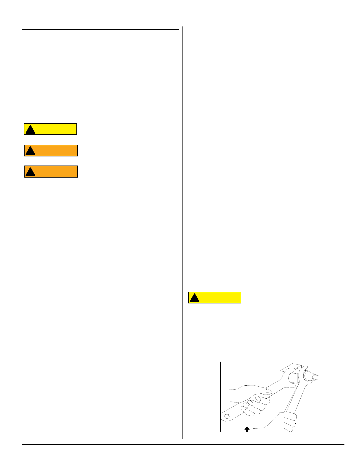
Fig. 1 - Double-wrenching gas fittings ..................................................... 3
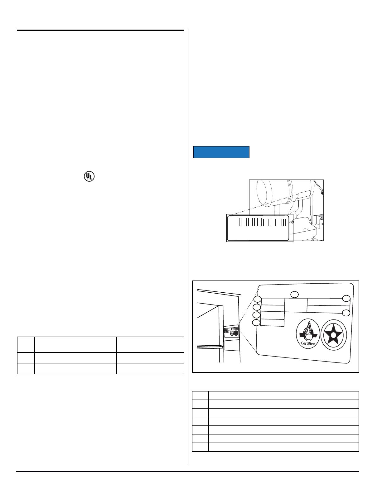
Fig. 2 - Cooling unit bar code label location. ........................................... 4
Fig. 3 - Refrigerator information label location ....................................... 4
Fig. 4 - Exploded front view .................................................................... 6
Fig. 5 - Exploded rear view .................................................................... 7
Fig. 6 - Typical roof exhaust venting .....................................................8
Fig. 7 - Thermostatic switch for fans. .................................................... 10
Fig. 8 - Movable door seal. .................................................................... 10
Fig. 9 - Temperature monitor control ......................................................11
Fig. 10 - Burner Box Location .............................................................. 12
Fig. 11 - Burner/Orifice Assembly ......................................................... 12
Fig. 12 - Control Locations ................................................................... 12
Fig. 13 - Mode Indicators ..................................................................... 13
Fig. 14 - Continuous 12 Volts ............................................................... 15
Fig. 15 - Switched 12 Volts ................................................................... 16
Fig. 16 - Magnet position ....................................................................... 22
Fig. 17 - Wiring Diagram ...................................................................... 29
Fig. 18 - Wiring Pictorial ........................................................................ 30
Fig. 20 - 2118 upper rear wiring ............................................................ 31
Fig. 21 - 2118 lower rear wiring ............................................................ 31
Fig. 23 - 2118IM lower rear wiring ......................................................... 32
Fig. 22 - 2118IM and 2118IMD upper rear wiring .................................. 32
Fig. 24 - 2118IMD lower rear wiring ...................................................... 33
2118, 2118IM, 2118IMD Series
FRENCH AND SPANISH TEXT BEGINS ON PAGE 35.
2
www.norcold.com
Safety
CAUTION
WARNING
WARNING
CAUTION
It is not possible to anticipate all of the conceivable ways or conditions under which the refrigerator may be serviced or to provide
cautions as to all of the possible hazards that may result. Standard
and accepted safety precautions and equipment should be used
when working on electrical circuits and handling toxic or ammable
materials. Safety goggles and other required protection should be
used during any process that can cause material removal, such as
when removing a leaking cooling unit and cleaning components.
Read this manual carefully and understand the contents before
working on the refrigerator. Be aware of possible safety hazards
when you see the safety alert symbol on the refrigerator and in this
manual. A signal word follows the safety alert symbol and identies
the danger of the hazard. Carefully read the descriptions of these
signal words to fully know their meanings. They are for your safety.
This signal word means a hazard, which if
!
!
ATTENTION
ignored, can cause small personal injury
or much property damage.
This signal word means a hazard, which
if ignored, can cause dangerous personal
injury, death.
Do not use leak test solutions that contain
ammonia or chlorine. Ammonia and chlorine degrade copper and brass components.
The cooling unit is a sealed system under
pressure! Do not try to repair or recharge
the cooling unit. Do not bend, drop, weld,
drill, puncture, saw, or strike the cooling
unit.
Handle a leaking cooling unit with extreme
caution! The cooling unit contains ammonia, hydrogen, and sodium chromate.
Ammonia can cause severe skin and eye
burns. Hydrogen is highly ammable, can
ignite and burns with an intense ame.
Certain chromium compounds, such as
sodium chromate, are carcinogenic.
Do not use extension cords. Do not remove the grounding prong from the refrigerator AC power cord. Do not use a two
prong adapter to connect the refrigerator
to the AC outlet.
!
ATTENTION
Norcold refrigerators are designed and
equipped for the use of propane gas
only. Do not modify, alter, or equip the
refrigerator to any other fuel (natural gas,
butane, etc.).
Incorrect installation, adjustment, alteration, or maintenance of the refrigerator
can cause personal injury, property damage, or both.
Do not smoke, light res, or create sparks
when working on propane gas system.
Propane gas is highly ammable and
explosive. Do not use an open ame for
leak testing any of propane gas system
components.
Always use two wrenches to tighten or
loosen propane gas connections. Damaged connections, piping, and components create the potential for gas leaks.
All electrical connections and repairs to
the refrigerator must comply with all appli-
cable codes. Refer to the certication and
code requirements section of the Installation Manual.
Turn off AC power and DC power sources
before attempting to remove, service, or
repair any of the refrigerator’s electrical
or electronic components. Do not work on
live electrical circuits.
Do not over-fuse electrical circuits. Use
specied fuses and AWG wire sizes. The
specication section of this manual pro-
vides fuse size information. Refer to the
Installation Manual for the correct AWG
wire size specications.
Prevent child entrapment! Before disposing of the refrigerator, remove all doors
and fasten all shelves with retainers.
Make sure all hardware such as hinges
and fasteners (retaining screws, etc.), are
properly fastened.
Obey the instructions in this manual with
regard to intake and exhaust venting
specications.
Do not install the refrigerator directly on
carpet. Put the refrigerator on a metal or
wood panel that extends the full width and
depth of the refrigerator.
!
Some of the refrigerator’s metal components have sharp corners and edges.
Wear hand protection, such as cut resistant gloves, and exercise extreme care
when handling the refrigerator.
www.norcold.com
Do not modify, bypass, or eliminate any of
the refrigerator’s electrical components,
electronic circuits, or propane gas system
components.
Do not wet or spray liquids on or near
electrical outlets, connections or components. Most liquids, including leak detection solutions, are electrically conductive
and pose the potential for an electric
shock hazard, short electrical components, damage electronic circuits, and/or
ignite a re.
Fig. 1 - Double-wrenching gas ttings
3
NOR000129A-1
SERVICE MANUAL
NOTICE
xxxxxxxxxxxxxx
xxxxxxxxxxxxx
xxxxxxxxxxxxxxx
xxxxxxxxxxxx
xxxxxxxxxxxxxxxxxxxxxx xxxxx
xxxxxxxxxxxxxxxxxxxxx
xxxxxx
xxxxxxxxxxxxxxxxxxxxx xxxx
xxxxxxxxxxxxxxxxxxx
xxxxxxxxxxxxxxxxxxxx
xxxxx
xxxxxxxxxxxxxxxxxxxxxxx xx
xxxxxxxxxxxxxxxxxxxxxxxxx
xxxxxxxxxxxxxxxxxxxxxxx
xxxxxxxxxxxxxxxxxxxxxxx
D
E
S
I
G
N
C
E
R
T
I
F
i
E
SA
NORCOLD
x
x
x
x
xx
x
x
x
x
x
x
x
xx
x
x
x
x
x
x
x
x
x
x
x
x
Introduction
■ Recreational Vehicle (RV) Make/Model/Year
About This Manual
This service manual provides maintenance, diagnostic, and repair
information for NORCOLD
sorption refrigerators. It is a reference tool designed for technicians
who are knowledgeable in the theory and operation of gas/electric
absorption refrigerators, liqueed petroleum (LP) gas–propane–
systems, and AC/DC electrical systems as installed in a variety of
recreational vehicles (RV).
All information, illustrations, and specications contained in this
publication are based on the latest product information available
at the time of publication. NORCOLD
changes at any time without notice.
®
2118, 2118IM, 2118IMD Series gas ab-
®
reserves the right to make
Certication and Code Requirements
NORCOLD® gas/electric absorption refrigerators are certied
under the latest edition of ANSI Z21.19B standards for installation
in mobile homes or recreational vehicles, and with the Canadian
Standards Association CAN/CGA-1.4-M94.
Electrical components are compliant.
About Installation
Refrigerator installation must conform with the 2118, 2118IM,
2118IMD Series Installation Manual for the NORCOLD
warranty to be in effect. Installation must also comply with appli-
cable local codes and standards set by the relevant certication
agency.
®
limited
Model Identication
2118, 2118IM, and 2118IMD Series models are shipped from the
factory as 2-Way units to operate on propane gas or 120 volts AC
electric.
Letter(s) appended to the model number identify factory installed
accessories. See Fig. 2.
Cooling Unit Serial Number
The cooling unit serial number appears on the cooling unit bar
code label. The label is afxed to the surface of the cooling unit
leveling chamber.
Be sure to have the cooling unit serial
number available if you need technical
support on this component.
Refrigerator Model Number
N000036A-1
1167359
NORCOLD
Replacement Parts
Use only authorized NORCOLD® replacement parts. Generic parts
do not meet NORCOLD
performance. The use of unauthorized aftermarket or generic replacement parts voids the refrigerator’s limited warranty coverage.
®
specications for safety, reliability, and
Technical Assistance
If unable to resolve technical issues using the information provided
in this manual, technical support is available through NORCOLD
Customer Service Center:
Telephone: 1-800-444-7210
(
Fax: 1-734-769-2332
3
World Wide Web: www.norcold.com.
8
The following information is required to process technical support
requests:
■ Refrigerator Model Number
■ Refrigerator Serial Number
■ Refrigerator Cooling Unit Serial Number
2118, 2118IM, 2118IMD Series
Fig. 2 - Cooling unit bar code label location.
xxxxxxxxxxxxxxxxxxxxxxxxxxx
xxxxxxxxxxxxxxxxxxxxxxxxxxx
NORC OLD
312
Serial Number
Model Number
313
Group Code
314
Input Pressure
®
315
BTUH
xxxxxxxxxxxxxxxxxxxxxxxxxxx
xxxxxxxxxxxxxxxxxxxxxxxxxxx
xxxxxxxxxxxxxxxxxxxxxxxxx
xxxxxxxxxxxxxxxxxxx
xxxxxxxxxxxxxxxxxxxxxxxxx
xxxxxxxxxxxxxxxxxxxxxxxxx
xxxxxxxxxxxxxxxxxxxxxxxxx
xxxxxxxxxxxxxxxxxxxxxxx
xxxxxxxxxxxxxxxxxxxxxxx
Refrigerant
x.xx
LBS.
test pressure
Fig. 3 - Refrigerator information label location
312 Serial Number
313 Model Number
314 Group Code
315 BTU / h
316 Amount of refrigerant in cooling system
317 AC Voltage / Amperage
318 DC Voltage / Amperage
4
316
xxx VOLTS - AC xx HZ
x.xx AMPS xxx Watts
xx VDC xx HZ
x.x AMPS xx xx Watts
E
D
SA
C
E
R
T
www.norcold.com
317
318
I
G
S
N
D
E
i
F
I

Specications
Rough Opening Dimensions
(H x W x D) --------------------------------------------------------------------------------------- 68.94 - 69.06 in. x 35.94 - 36.04 x 24.00 - 24.13 in.
Internal Capacities
Total capacity ----------------------------------------------------------------------------------------------------------------------------------------18.18 cu. ft.
Freezer ------------------------------------------------------------------------------------------------------------------------------------------------- 5.92 cu. ft.
Fresh food compartment --------------------------------------------------------------------------------------------------------------------------12.57 cu. ft.
Controls
Type ------------------------------------------------------------------------------------------------------------------ Electronic with built-in self diagnostic
ON/OFF, MODE, TEMP SET switches -------------------------------------------------------------------- LCD assembly with ush push buttons
Temperature setting range ------------------------------------------------------------------------------------------------- 1 = cold through 9 = coldest
Temperature / defrost sensing services ------------------------------------------------------------------------------------------------------ Thermistors
Fresh food thermistor ------------------------------------------------------------------------------------------------- Located on 2nd n from the right
Fans thermistor --------------------------------------------------------------------------- Located at rear of refrigerator on left most condenser n
DC Power
Electronic controls voltage requirement ----------------------------------------------------------------------------------------------- 10.5 to 15.4 VDC
Fuse-power board ------------------------------------------------------------------------------------------------ Automotive Blade, Type APR-5A-Tan
DC Current Draw at nominal 12 VDC
Fresh food blower ----------------------------------------------------------------------------------------------------------------------------- 0.200 - 0.300 A
Freezer blower---------------------------------------------------------------------------------------------------------------------------------- 0.140 - 0.185 A
Divider heater -------------------------------------------------------------------------------------------------------------------------------------------- 0.275 A*
Flapper heater ------------------------------------------------------------------------------------------------------------------------------------------- 0.417 A*
Perimeter heater ----------------------------------------------------------------------------------------------------------------------------------------0.275 A*
Interior light ----------------------------------------------------------------------------------------------------------------------------------------------- 0.500 A*
Gas valve -------------------------------------------------------------------------------------------------------------------------------------------------0.146 A*
External ventilation fans (2 at condenser) ---------------------------------------------- 0.430 A @ 12VDC - 2/29/2016 and before (per fan)*
----------------------------------------------------------------------------------------------------------0.277@ 12VDC - 3/1/2016 and after (per fan)*
External ventilation fan (1 at absorber) ------------------------------------------------------------------------------------------------------------0.140 A*
Ice maker water line heater (IM models only) ---------------------------------------------------------------------------------------------------0.167 A*
Ice maker water line heater (IMD models only) -------------------------------------------------------------------------------------------------1.250 A*
Dispenser water line heater (IMD models only) ------------------------------------------------------------------------------------------------- 0.167 A*
Dispenser water valve heater (IMD models only) ----------------------------------------------------------------------------------------------0.458 A*
AC power
AC input voltage requirements ------------------------------------------------------------------------------------------------------------ 108 to 132 VAC
Fuse-power board ------------------------------------------------------------------AGC Series, 8A, Fast Acting, Glass Tube (1/4 in. x 1-1/4 in.)
AC Current Draw
AC heaters (2) -------------------------------------------------------------------------------------------------------------------- 300 W, 2.5 A (per heater)
AC heater resistance -------------------------------------------------------------------------------------------------------46.0 Ω to 51.0 Ω (per heater)
Ice maker (IM models only) --------------------------------------------------------------------------------------------------------------180W at 115 VAC
Ice maker water valve (IM models only) ---------------------------------------------------------------------------------------------------------0.210 A**
Ice maker water valve (IMD models only) -------------------------------------------------------------------------------------------------------0.145 A**
Propane gas
Operating pressure ----------------------------------------------------------------------------------------------------------------------10.5 - 11.5 inch w.c.
Burner rating (8-slot burner / LP22 orice) -------------------------------------------------------------------------------- 3000 Btu/h at 11 inch w.c.
Burner orice size ------------------------------------------------------------------------------------------------------------------------------------------ LP22
Flame sensing ------------------------------------------------------------------------------------------------ Electronic through spark sense electrode
Electrode tip-to-burner gap ------------------------------------------------------------------------------------------------------------------1/8 to 3/16 inch
Off-level operating limits
Side-to-side-------------------------------------------------------------------------------------------------------------------------------3 degrees-maximum
Front-to-back ----------------------------------------------------------------------------------------------------------------------------- 6 degrees-maximum
* = Calculated, ** = Actual
www.norcold.com
5
SERVICE MANUAL
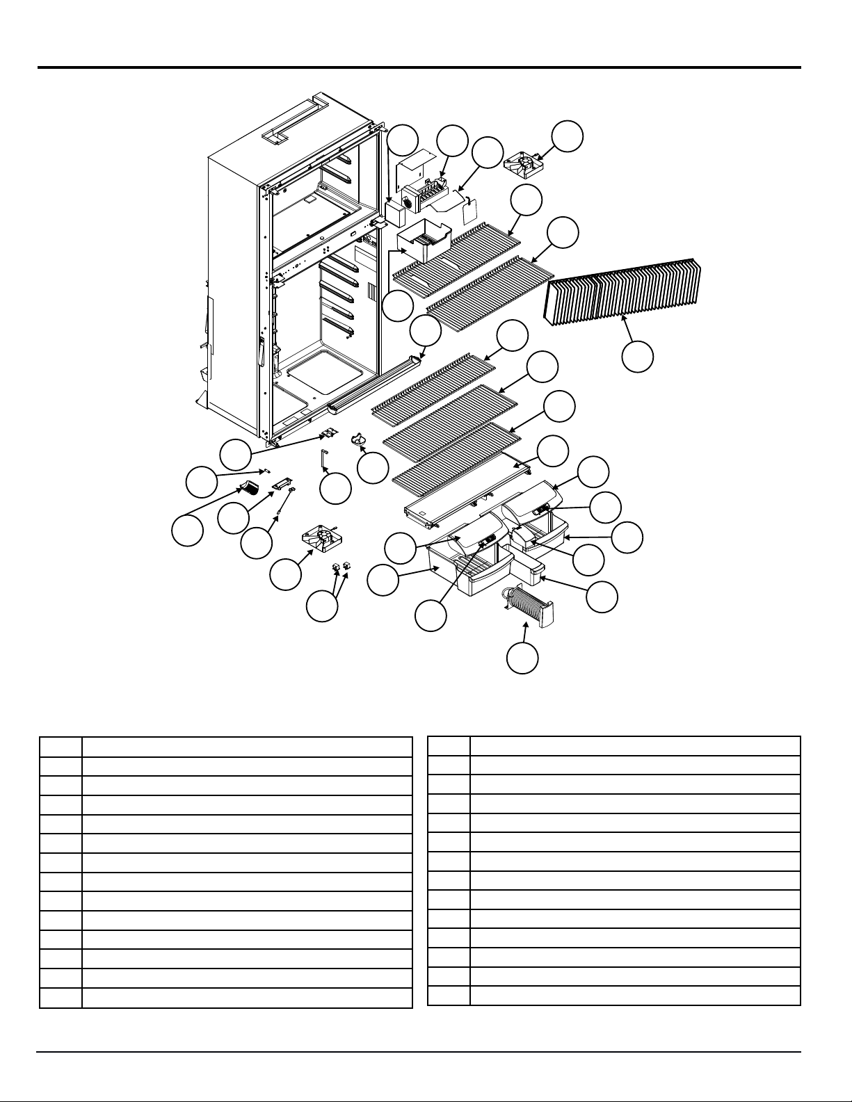
Exploded View
23
22
21
12
13
11
20
24
25
18
17
11
16
14
15
19
27
8
7
10
9
6
2
3
2
1
5
1
4
3
NOR000450B
Fig. 4 - Exploded front view
Description
No.
1 Crisper
2 Crisper Lid
3 Crisper Lid Vent
4 Beverage Bin
5 Beverage Bin Cover
6 Crisper Cover Assembly
7 Middle Wire Shelf
8 Top Wire Shelf
9 Full wire Shelf
10 Fin Assembly
11 Blower Assembly
12 Guide Block
13 Thermistor
2118, 2118IM, 2118IMD Series
26
14 Freezer Wire Shelf With Hump
15 Freezer Wire Shelf
16 Ice Maker Shutoff Arm
17 Ice Maker
18 Ice Maker Cover
19 Crisper Bin
20 Light Switch
21 Lamp Bracket Assembly
22 Light Bulb
23 Light Cover
24 Drip Hose
25 Drip Cup
26 Dispenser Reel Assembly
27 Drip Tray
6
www.norcold.com
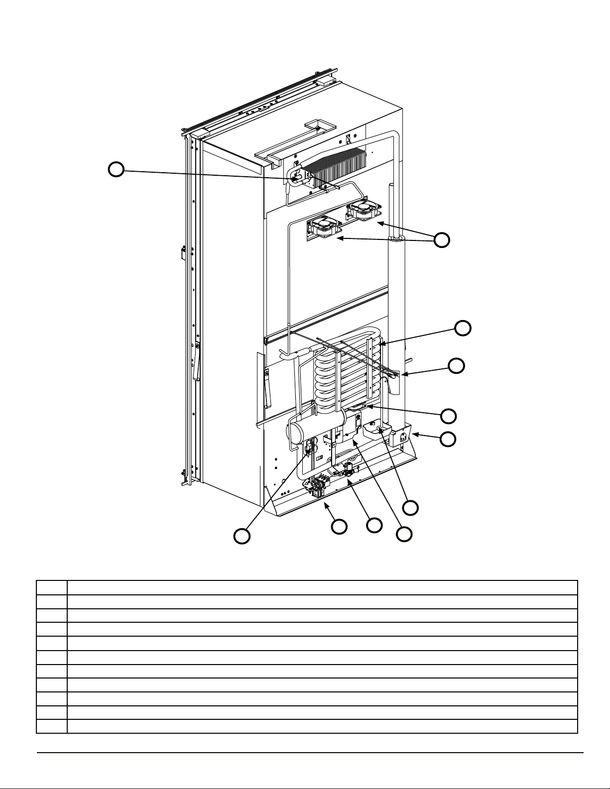
Exploded View, cont'd.
24
23
25
NOR000206A
Fig. 5 - Exploded rear view
Description
No.
17 AC Heaters
18 Drip Cup
19 Gas Valve
20 Water Valve (IM and D models only - D version shown)
21 Temperature Monitor Control (TMC)
22 Power Board
23 Blower Assembly
24 Fan Thermostat
25 Cooling System
26 Burner Box
21
20
17
23
26
18
19
22
www.norcold.com
7
SERVICE MANUAL
WARNING
General Information
WARNING
To conrm that installation is adequate, check for:
■ Adequate ventilation - refer to "Ventilation Requirements."
■ Both gas and electrical components installed and operating in a
safe condition.
■ Adequate seal between refrigerator mounting ange and cut-out
opening.
■ Installed on a solid oor (not on carpet) and secured.
This refrigerator is not intended to be
!
ATTENTION
operated as a free standing unit (i.e.
where the products of combustion are not
completely isolated from the living area) or
installed in such a way as to conict with
these installation instructions. Unapproved
installations could result in safety risks or
performance problems.
Enclosure
The cabinet that encloses the refrigerator is built by the RV manufacturer. Depending on cabinet depth, height, and width certain
bafes may be present when cabinet clearances exceed installation guidelines and specications.
Bafes
Bafes prevent hot air buildup “pocketing” between the refrigerator
cabinet and the enclosure walls and/or ceiling. An enclosure may
be tted with:
■ An absorber bafe and a condenser bafe
■ Side bafes [320] (See Fig. 6)
■ Vertical top bafe [13]
■ Vertical angled bafes
■ Box bafe
■ Or a combination of any of the above.
Ventilation
Overview
The installed unit must
!
ATTENTION
Certied installation needs one lower intake vent and one upper
exhaust vent. Install the vents through the side wall of the vehicle
exactly as instructed in the Installation Manual. Any other installa-
tion method voids both the certication and the factory warranty of
the refrigerator.
The bottom of the opening for the lower intake vent, which is also
the service access door, must be even with or immediately below
the oor level. This allows any leaking propane gas to escape to
the outside and not to collect at oor level.
American Gas Association/Canadian Gas Association (AGA/CGA)
certication allows the refrigerator to have zero (0) inch minimum
clearance at the sides, rear, top, and bottom. While there are no
maximum clearances specied for certication, the following maxi-
mum clearances are necessary for correct refrigeration:
isolated from the combustion system of the
refrigerator and it must have complete and
unrestricted ventilation of the ue exhaust
which, in gas mode, can produce carbon
monoxide. The breathing of carbon monoxide fumes can cause dizziness, nausea, or
in extreme cases, death.
be completely
For complete detail about any necessary bafe(s), refer to the
refrigerator Installation Manual.
Lower Intake Vent
Ventilation and combustion air ow through the lower intake vent
[9] (See Fig. 6), which also serves as the service access or door.
The lower intake vent needs be kept clear of obstructions that may
restrict the ow of fresh air into the enclosure.
319
179
Front of RV
12
13
Bottom 0 inch min. 0 inch max.
Each Side 0 inch min 1/4 inch max.
Top 0 inch min. 1/4 inch max.
Rear 0 inch min. 1 inch max.
These clearances plus the lower and upper vents cause the natural
air draft that is necessary for good refrigeration.
Cooler air goes in through the lower intake vent, goes around the
refrigerator coils where it removes the excess heat from the refrigerator components, and goes out through the upper exhaust vent.
If this air ow is blocked or decreased, the refrigerator may not cool
correctly.
Each NORCOLD model is certied by AGA and CGA for correct
ventilation.
2118, 2118IM, 2118IMD Series
NOR000201A
Fig. 6 - Typical roof exhaust venting
8
320
9
www.norcold.com
Ventilation, cont’d.
WARNING
WARNING
WARNING
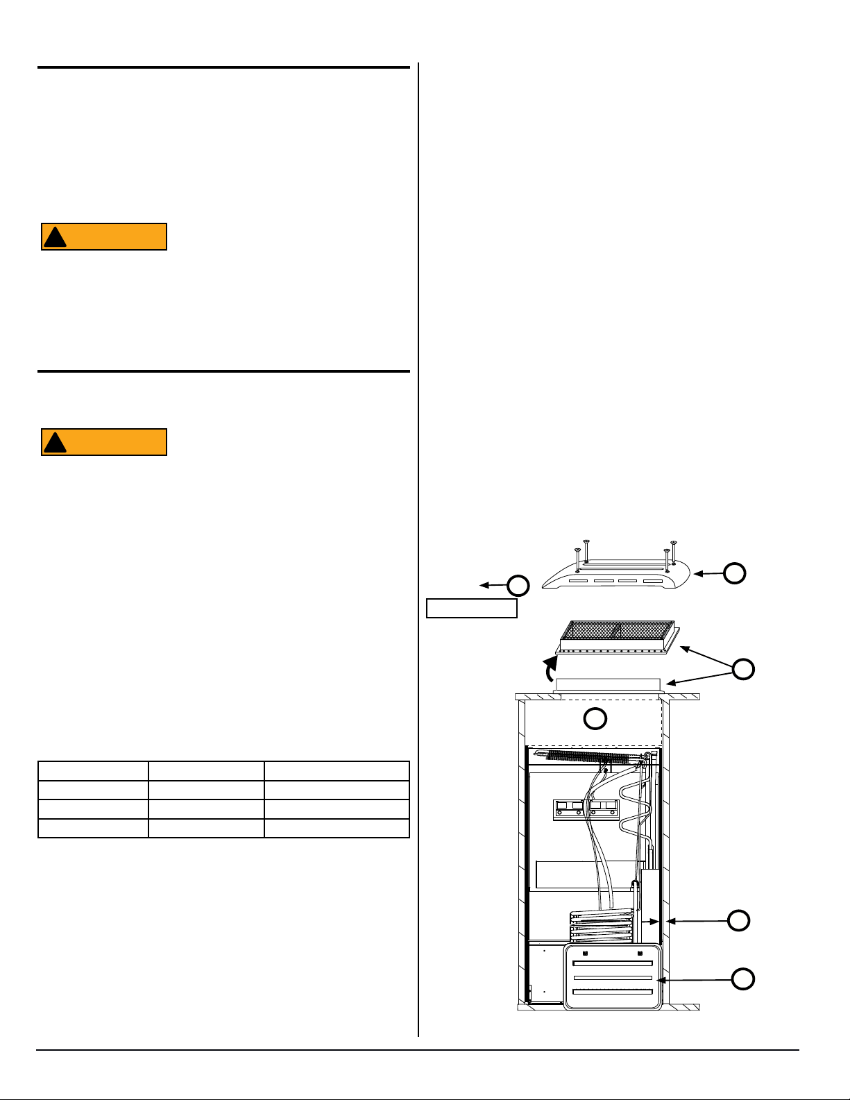
Exhaust Vent
Warm air and combustion gases ow out of the enclosure through
the exhaust vent. The exhaust vent can be either a roof exhaust
vent [12] or an upper sidewall exhaust vent.
The roof exhaust vent has a non-removable metal mesh screen
to prevent leaves, birds, rodents and/or debris from entering the
enclosure.
inches Water Column).
■ If the pressure of the compressed air is more than 1/2 psig (14
inches Water Column), remove the gas supply line from the 3/8
inch male are tting of the refrigerator before the test.
■ If the pressure of the compressed air is equal to or less than
1/2 psig (14 inches Water Column), push and hold the ON/OFF
button (
) for one (1) second before the test.
Electrical Connections
Roof Cap
The roof cap [319] ts over exhaust vent. The sloped end always
faces the front of the RV [179] (See Fig. 6). It is held in place by
four 2-1/2” long Phillips head screws.
Propane Gas Connections
The refrigerator operates on propane gas at a pressure of 10.5
inches Water Column min. to 11.5 inches Water Column max.
!
ATTENTION
■ Do not smoke, or use an open ame near the propane gas
system.
■ Do not use an open ame to examine for leaks.
■ Do not connect the refrigerator to the propane gas tank without
a pressure regulator between them.
■ To avoid possible propane gas leaks, always use two wrenches
to tighten or loosen the propane gas supply line connections.
■ Leaking propane gas can ignite or explode and result in danger-
ous personal injury or death.
!
ATTENTION
Leak Test-Detergent
Using a solution of liquid detergent and water:
■ Examine the propane gas supply system for leaks: make sure
the propane gas supply line and all gas connections have no
leaks. Do not use any liquid that contains ammonia.
Leak Test-Compressed Air
If you use compressed air for the test:
■ The pressure of the compressed air at the 3/8 inch male are
tting of the refrigerator must not be more than 1/2 psig (14
Be very careful when working on or near
the propane gas system.
Do not allow the leak detecting solution
to touch the electrical components. Many
liquids are electrically conductive and can
cause a shock hazard, electrical shorts,
and in some cases re.
120 Volts AC Electrical Connection
The refrigerator is equipped with a three prong plug for protection
against shock hazard and must be connected into a recognized
three prong attachment receptacle. The free length of cord is 24”.
The cord must be routed so as not to come in contact with the
burner cover, ue pipe or any other component that could damage
the cord insulation.
Do not remove (cut)grounding plug from
!
ATTENTION
■ Verify AC power cord is in a grounded three-prong receptacle.
■ Verify receptacle is within easy reach of the lower intake vent.
■ Verify power cord does not touch the burner cover, the ue
pipe, or any hot component that could damage the insulation of
the power cord.
the refrigerator AC power cord. Removal
of this prong can result in a severe electrical shock, as well as voiding the refrigera-
tor’s electrical certication and warranty.
12 Volts DC Electrical Connection
The refrigerator controls require 12 volt DC to operate. The
minimum control voltage is 10.5 volts DC. The maximum control
voltage is 15.4 volts DC.
Polarity
The correct polarity of the DC leads to the power board connections is:
■ The + 12 volt DC (positive) supply wire from the battery must be
connected to the terminal marked “12VDC” on the power board.
■ The - 12 volt DC (negative) supply wire from the battery must be
connected to the terminal marked “GND” on the power board.
Power Board Fuses
The DC controls circuit is protected by an Automotive Blade, Type
APR-5A-Tan fuse located on power board terminal F1. The AC
circuit is protected by an AGC Series, 8A, Fast Acting, Glass Tube
(1/4 in. x 1-1/4 in.) fuse located on power board terminal F2.
■ See wiring diagram in this manual. Both negative and positive
supply wires require 1/4” female quick connect terminals.
www.norcold.com
9
SERVICE MANUAL
Electrical Connections, cont’d.
NOTICE
WARNING
■ Use a minimum of 18AWG wire for supply wire and maximum 6
A in-line fuse for the DC power supply wires.
■ Make sure an in-line fuse is installed on the DC positive wire,
as near the battery as possible, between the battery and the
terminal block of the refrigerator.
from the enclosure to test the thermostatic
switch. If the vehicle has an upper sidewall exhaust vent, you are able to test the
thermostatic switch by removing the upper
sidewall vent.
322
This in-line fuse is necessary for added
!
ATTENTION
safety, even though the refrigerator has a
DC fuse in the control assembly.
Replacement Fuse Size
AC circuit AGC Series, Fast Acting,Glass Tube (1/4 in.x 1 -1/4 in.)
DC circuit Automotive Blade, Type APR-5A-Tan
Electrical Components
Fresh Food Compartment Light
The fresh food compartment light is turned on and off by door
operated switches. Each switch is located in the top of fresh food
compartment above each door.
Divider Heater
The divider heater is permanently “foamed into” the divider between the freezer compartment and the fresh food compartment.
The divider heater warms this area to prevent condensation from
forming. Powering on the refrigerator automatically powers on the
divider heater. Power to the heater is continuously supplied by the
power board.
12 Volt DC Fans
12 volt DC fans increase ventilation of the cooling system. Two (2)
larger fans are located near the condenser on the rear of the cooling system foam plug. The third smaller fan is located below the
absorber coils of the cooling system.
All of the fans are unidirectional. The larger fans each draw 0.430
amps @ 12 volts DC. The smaller fan draws 0.140 amps @ 12
volts DC. Fan resistance through the fan motor circuit is approximately 1.8 ohms.
The fans are controlled by a thermostatic switch.
10
321
323
NOR000202A
Fig. 7 - Thermostatic switch for fans.
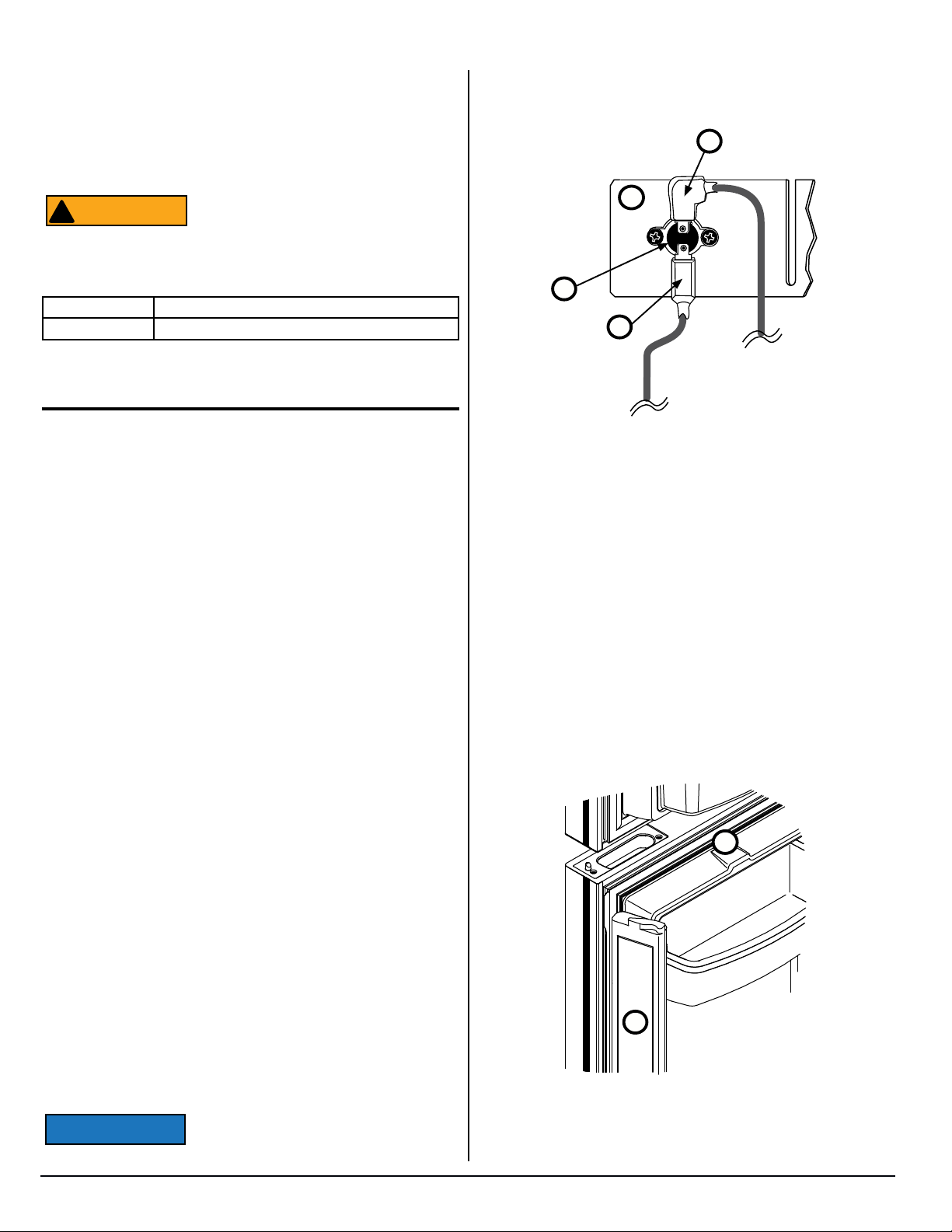
Movable Door Seal
The apper assembly [324] (See Fig. 8) is hinged onto the left hand
door [10] of the fresh food compartment. The apper assembly pro-
vides the vertical sealing surface between the fresh food compartment doors for their inboard gaskets.
The apper is equipped with a 12 volt DC moisture reduction
heater. The heater is supplied power through a wire harness
foamed into the door.
The heater is turned on when spring pins, on the hinge side of the
door, make contact with the permanent contacts that are in the side
of the refrigerator cabinet. The left hand fresh food compartment
door must be fully closed to close the connection. Powering on the
refrigerator automatically energizes the apper heater circuit.
Verify that the heater is operating by touching the exterior sur-
10
Thermostatic Switch
The thermostatic switch [321] is located on the rst condenser n
[10] (See Fig. 7). Incoming +12 volt DC [322] is fed through the upper terminal of the thermostatic switch. The +12 volt DC out [323]
connects to the lower terminal of the thermostatic switch.
The switch turns the fans on and off. The fans come on when the
temperature of the rst condenser n is about 130° F (54.4° C) and
turn off at about 115° F (46°C).
If the vehicle has a roof exhaust vent,
you may need to remove the refrigerator
2118, 2118IM, 2118IMD Series
Fig. 8 - Movable door seal.
10
324
Art01813
www.norcold.com
Electrical Components, cont’d.
face of the apper assembly. The surface of the apper assembly
should be slightly warm to the touch.
If the apper surface feels cold to the touch or is wet, troubleshoot
the heater as follows:
1. Check for any bent, broken or missing spring pins.
2. Check the door alignment. If needed, align the door so that
all of the spring pins make full contact with the center of the
contacts in the cabinet.
3. Check the heater resistance. Resistance reading should be
between 26 ohms and 31 ohms.
4. Replace the apper assembly if the heater is open, shorted, or
if the resistance is not between 26 ohms and 31 ohms.
NOR000212A-1
Temperature Monitor Control (TMC)
The purpose of the temperature monitor control is to prevent damage to the cooling unit due to an overheating condition in the boiler.
An overheating condition may be caused by one or a combination
of the following:
■ Insufcient or obstructed ventilation.
■ Inadequate installation in enclosure.
■ Heat deector cap blocked by insulation.
■ Heat deector cap jammed against ue opening.
■ Exceeding off-level limits.
■ Cooling unit blockage.
The temperature monitor control [326] acts as a temperature
supervising device (See Fig. 9). It uses a thermocouple, which is
positioned on the boiler, to provide the best possible monitoring of
temperature.
If the temperature of the boiler rises to an abnormal level, the high
temperature monitor opens to prevent the boiler from overheating.
The controls are programmed to detect when the monitor is open.
If the switch is open or not connected to power board terminals
LIMIT IN and LIMIT OUT, the controls:
■ Display fault code “LI” “oP”.
■ Stop AC and propane gas operation.
326
Fig. 9 - Temperature monitor control
Preventative Maintenance
An annual maintenance check is strongly recommended:
■ Leak test the gas lines.
■ Check combustion seal; repair or replace, if necessary (Visual
check without removing the refrigerator.).
■ Inspect or clean the burner or burner orice.
■ Check/adjust the electrode spark gap.
■ Insure the spark electrode tip is clean and that the electrode is
securely attached to the burner bracket.
■ Check/adjust AC and DC voltages and propane gas supply
pressure.
■ Check the gas safety valve (see procedure in this manual).
■ Insure that area around the burner and controls is free of de-
bris, oily rags, etc.
■ Inspect the controls, piping and wiring to insure that they are in
good condition.
THESE MAINTENANCE PROCEDURES MUST BE PERFORMED BY A
QUALIFIED SERVICE PERSON.
www.norcold.com
NORCOLD CANNOT ACCEPT RESPONSIBILITY FOR REPAIRS,
ADJUSTMENT, OR MAINTENANCE PERFORMED BY OTHER THAN A
QUALIFIED DEALER OR SERVICE CENTER.
11
SERVICE MANUAL
WARNING
Gas Flame Appearance
WARNING
WARNING
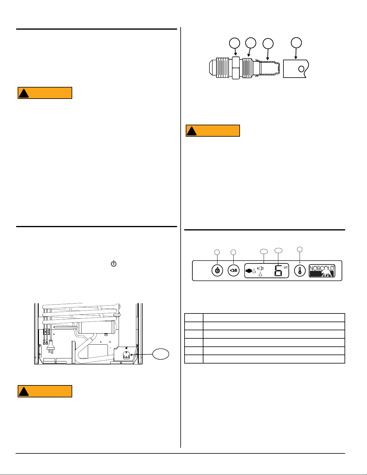
5. Remove the are nut from the orice assembly [77] (See Fig.
11).
While in propane gas operation, examine the appearance of the
gas ame:
■ Put the refrigerator on temperature setting 9 (the coldest tem-
perature setting).
■ Open the lower intake vent.
!
ATTENTION
■ Open the burner box door and look at the gas flame:
■ The ame should be a darker blue inside and a lighter blue
outside and should be a constant and steady shape.
■ The ame should not be yellow and should not have an er-
ratic and unstable shape.
■ Make sure the ame does not touch the inside of the ue
tube.
■ Close the burner box door.
■ The burner orifice should be cleaned as part of routine main-
tenance. Follow the Remove and Clean Burner Orifice instructions. If the flame is not at peak performance after it has been
cleaned, contact Customer Service.
The burner box cover can be hot. Wear
gloves to avoid burns.
77
80
79
78
Art 00956
Fig. 11 - Burner/Orice Assembly
6. Remove the orice assembly from the burner [78].
When cleaning, do not try to remove the
!
ATTENTION
7. Clean the orice assembly with alcohol only. Using a wrench,
assemble the orice assembly to the burner. Assemble the
are nut to the orice assembly. Examine all of the gas connec-
tions for leaks.
orice [79] from the orice adapter [80].
Removal will damage the orice and can
cause a propane gas leak. Leaking propane gas can ignite or explode and result
in dangerous personal injury or death. Do
not clean the orice with a pin or other
objects.
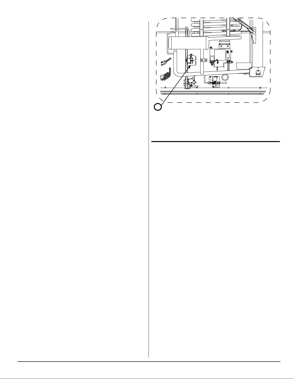
Remove and Clean the Burner Orice
Clean the burner and the burner orice annually. To clean the
burner orice:
1. Close the valve at the vehicle propane gas tank(s).
2. Push and hold the ON/OFF button (
turn the refrigerator off.
3. Open the lower intake vent.
4. Remove the burner box cover [165] (See Fig. 10) by removing
one (1) screw.
NOR000147A
Fig. 10 - Burner Box Location
To avoid possible propane gas leaks, al-
!
ATTENTION
ways use two (2)wrenches to loosen and
tighten the gas supply line at the 3/8 inch
male are tting.
) for one (1) second to
165
Controls
278
30 31
Art02493
280
Fig. 12 - Control Locations
No. Description
30 Power ON / OFF button
31 Mode button
32 Temperature set button
280 LCD (Liquid Crystal Display)
278 Temperature setting
Power ON / OFF Button
Push and release the Power ON / OFF button [30] (See Fig. 12) to
turn on the refrigerator.
Push and hold the Power ON / OFF button for one (1) second to
turn off the refrigerator.
32
set
2118, 2118IM, 2118IMD Series
12
www.norcold.com
Controls, cont’d.
Temperature Indicator
Mode Button
The mode button is manually operated and does not automatically
change the operating mode of the refrigerator.
Push and hold the Mode button [31] to scroll through the available
modes of operation of the refrigerator, one after the other. When
the desired mode indicator comes on, release the Mode button.
Or push and release the Mode button to change the available
modes of operation one at a time. There are one (1) Automatic and
two (2) Manual Mode of operation.
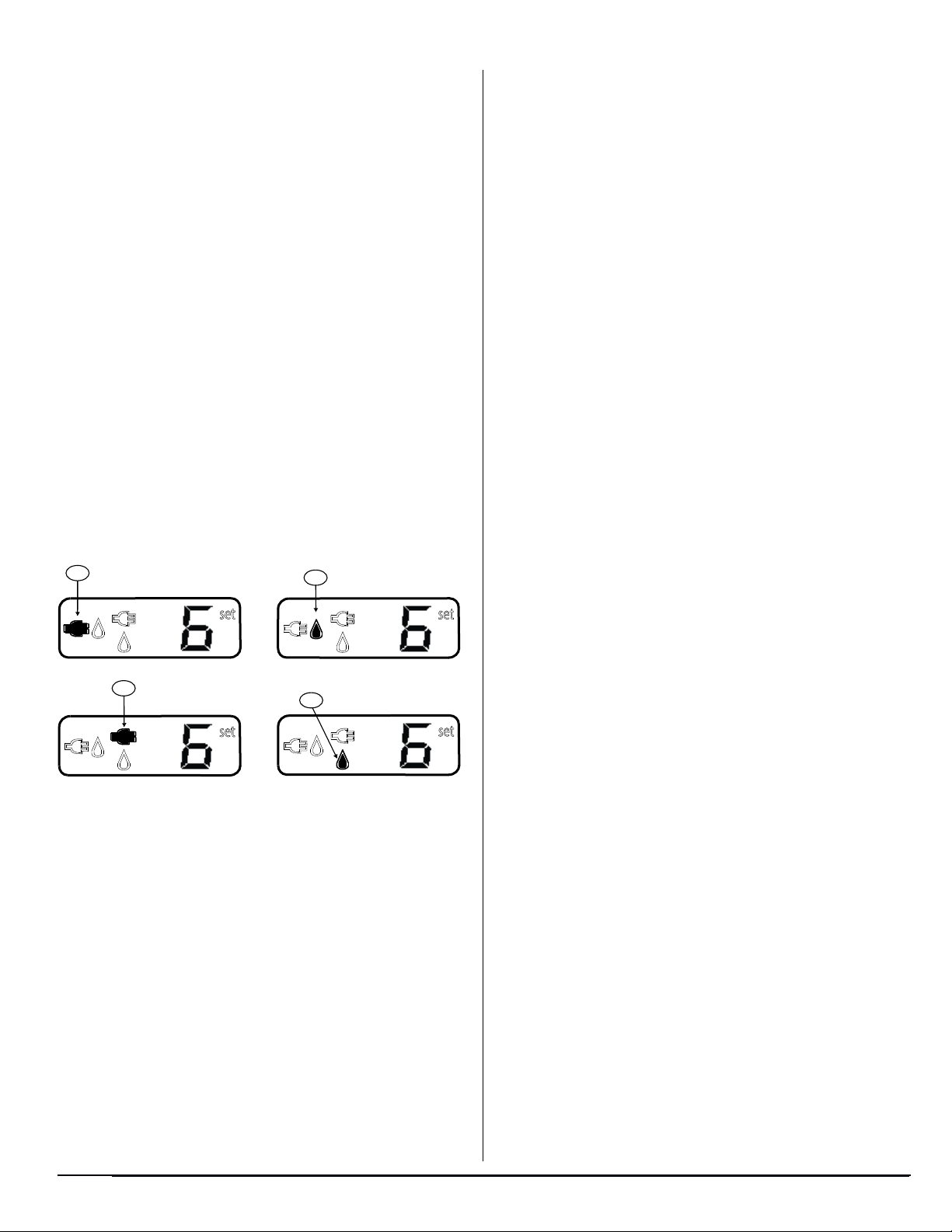
■ AUTO Mode: The refrigerator controls automatically select the
most efficient energy source that is available.
■ If available, the refrigerator controls select AC electric as the
power choice and the Auto mode AC indicator [281] comes
on (See Fig. 13).
■ If AC electric is not available, the controls select propane
gas as the power choice and the Auto mode propane gas
indicator [282] comes on.
■ MANUAL AC mode: The refrigerator operates using only AC
electric as the power source and the Manual mode AC indicator
[283] comes on.
■ MANUAL GAS mode: The refrigerator operates using only
propane gas as the power source and the Manual mode gas
indicator [284] comes on.
There are nine (9) temperature settings [278] (See Fig.12).
■ Number one (1) is the warmest temperature setting.
■ Number nine (9) is the coldest temperature setting.
Gas Operation
When either AUTO or MANUAL GAS mode is selected, the refrigerator attempts to ignite the propane gas burner. If unable to
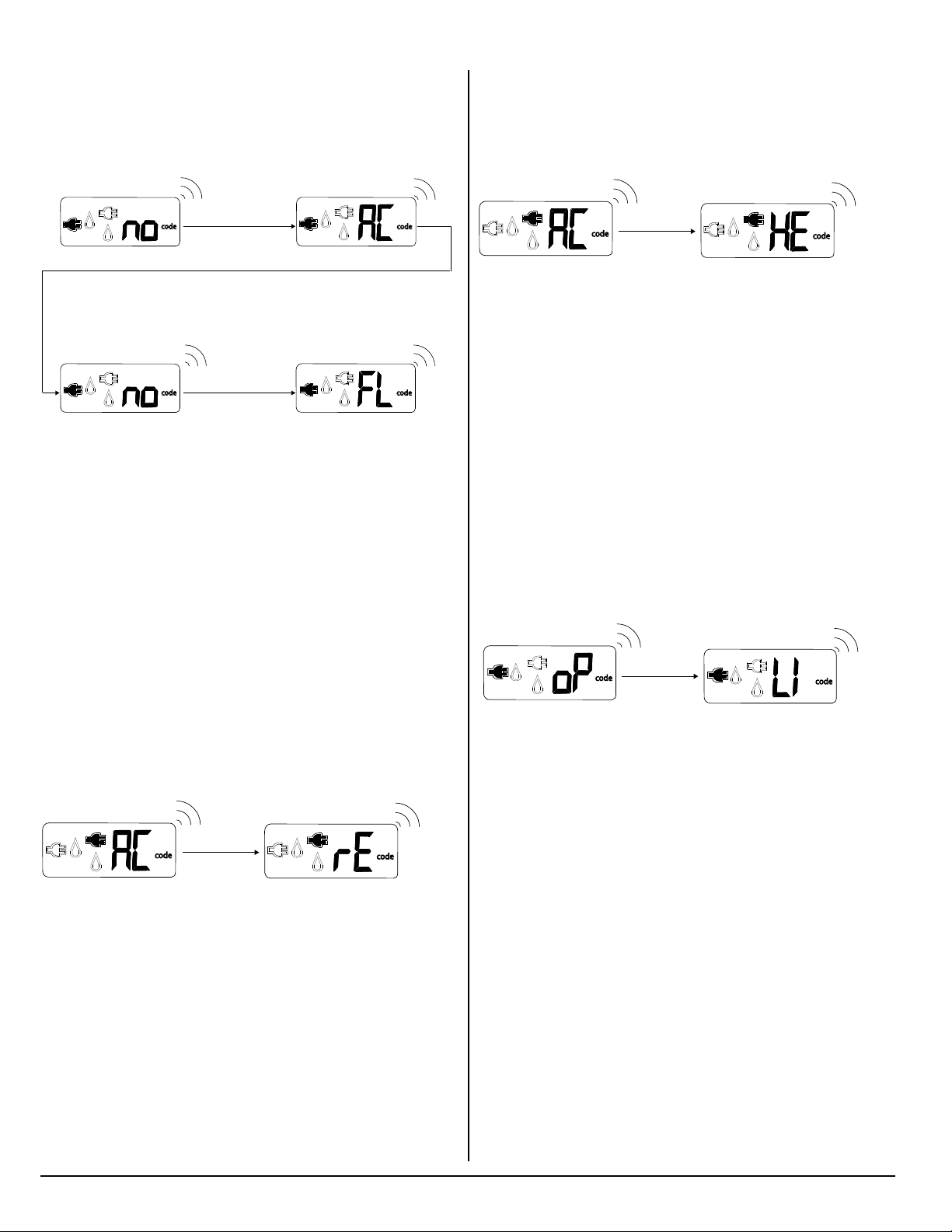
ignite the burner and to maintain a ame, the fault code “no” “FL”
appears in the LCD.
281
set
283
set
Art02493
282
set
284
set
Fig. 13 - Mode Indicators
Temperature Set Button
Push and hold the TEMPERATURE SET button [32] (See Fig.12)
to scroll through temperature settings, one after the other. Release
the TEMPERATURE SET button when the desired temperature
setting appears.
Or push and release the TEMPERATURE SET button to change
the temperature settings, one at a time.
www.norcold.com
13
SERVICE MANUAL
Modes of Operation
WARNING
Test the Gas Safety Valve
Gas Mode
In AUTO GAS mode and MANUAL GAS mode, the controls energize the solenoid coil to open the gas valve. Spring pressure closes
the valve when the controls stop the ow of current to the solenoid
coil.
The propane gas burner will cycle in response to the n tempera-
ture to maintain cabinet temperature.
The controls use an electronic sparker to ignite the propane gas at
the burner.
AC Mode
AUTO AC or MANUAL AC mode operation requires 108 to 132
volts AC. Voltage is to be supplied through a 2 pole, 3-wire, 20
Amp grounding type receptacle.
Two (2) 120 volt AC heaters generate the heat load required for
AUTO AC and Manual AC operation. Each heater is rated for 300
watts @ 120 volts AC. Each heater has a resistance value of 45 to
51 Ohms at ambient temperature. To replace heaters, the refrig-
erator must be removed from the enclosure.
Burn hazard! Allow canister and heaters
!
ATTENTION
The AC electric heaters will cycle in response to the n temperature to maintain the cabinet temperature.
to cool before attempting to remove and
replace.
Lighting Instructions
Before ignition or start up of the refrigerator:
■ Be sure the air ow in the lower intake vent, through the refrig-
erator coils and condenser, and out the upper exhaust vent is
not blocked or decreased.
■ Be sure there are no combustible materials in or around the
refrigerator.
1. Open the valve at the propane gas storage tank.
2. Push and release the ON / OFF button (
3. Push and hold the TEMPERATURE SET button until tem-
perature setting “9” appears.
4. Push the Mode button until the MANUAL GAS mode indica-
tor comes on.
).
To test the gas safety valve:
1. Open the lower intake vent.
2. Remove both white wires from the solenoid of the gas safety
valve on the rear of the refrigerator.
3. Insert volt ohm meter leads into the white wires and set the
meter to read DC volts.
4. Power ON the refrigerator; select MANUAL GAS mode.
5. Verify that the meter reads approximately 12 volts DC and that
the igniter sparks at the burner.
6. After approximately 30 seconds, the voltage measured at the
white wires will be 0 volts DC and the sparking at the burner will
cease. This means that the gas valve safety circuit is operating
correctly. The appropriate error code will appear on the optical
display.
7. Reconnect the white wires to the gas valve solenoid. It does
not matter which wire is attached to which terminal.
8. Close the lower intake vent.
9. Power OFF the refrigerator.
Diagnostic Pre checks
Prior to performing the diagnostic steps called out in the follow-
ing pages; rst do these important diagnostic pre-checks. In most
cases doing so, in and of itself, will remedy the problem at hand.
Make sure:
■ Door is closed and sealing correctly.
■ Unit vents are not blocked.
■ Ambient temperature is not unusually high (more than 110° F. /
43° C.)
■ Verify control panel works properly. The refrigerator is plugged
into a known working AC outlet with a voltage between 108 VAC
and 132 VAC.
■ Extension cords are not being used to supply AC power to the
refrigerator.
■ The refrigerator is connected to a known working DC power
supply and/or battery supplying between 10.5 VDC and 15.4
VDC.
■ Propane gas is available to the refrigerator and is regulated
between 10.5 inches and 11.5 inches w.c. (Inches of Water
Column).
■ The airflow through the intake and exhaust vents is not blocked
and the ventilation baffles are constructed correctly.
2118, 2118IM, 2118IMD Series
14
www.norcold.com
Fault Codes
Blank Display
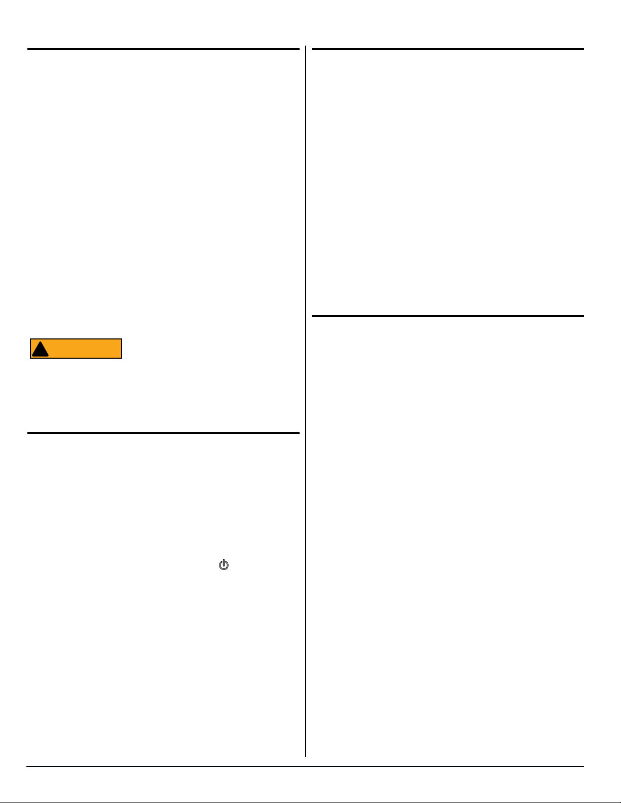
On-Off Theory of Operation:
Continuous 12-Volts (See Fig.14)
12VDC is supplied to the refrigerator at Power Board terminals
12VDC & GND [A]. This 12VDC travels through the Power Board
to fuse F1 [B] and then out to P1-6 [C]. Via the red-blue wire, the
12VDC exits the Power Board and enters the Display Board at
P1-1 [D]. The 12VDC travels through the Display Board to one side
of the normally open On-Off switch [E]. This 12VDC is referred
to as the continuous 12-volts because it is always present at the
one side of the On-Off switch when 12VDC power is applied to the
refrigerator.
2
P3
1
K3
K1
K4
U1
K5
K2
K6
WH-BK/BC-NR
1
2
35
4
6
P2
POWER BOARD/PANNEAUD’ALMENTATION
BK-NR
K3
K1
K2
BU-BL
F2 8-Amp
F1 5-Amp
B
K6
K5
YL-GN/JN-VE
12VDC/VCD (BAT POS)
12VDC/VCD (BAT NEG)
A
12VDC
GND
12
P4
-
125
K4
-
-
3
-
4
+
+
C
67
+
+
8
+
9
+
10
P1
LIMIT_OUT
LIMIT_IN
AC_HT_HI_2
AC_HT_HI
AC_HT_LO_2
AC_HT_LO
L2
L1
+
RD-YL/RG-JN
RD-BU/RG-BL
RD-YL/RG-JN
BU-BL
BK-NR
D
P1
1
ON-OFF
Vreg
2
3
4
5
MODE
E
P3
MICRO
DISPLAY BOARD /
TEMP
CARTE D’AFFICHAGE
NOR000240A
Fig. 14 - Continuous 12 Volts
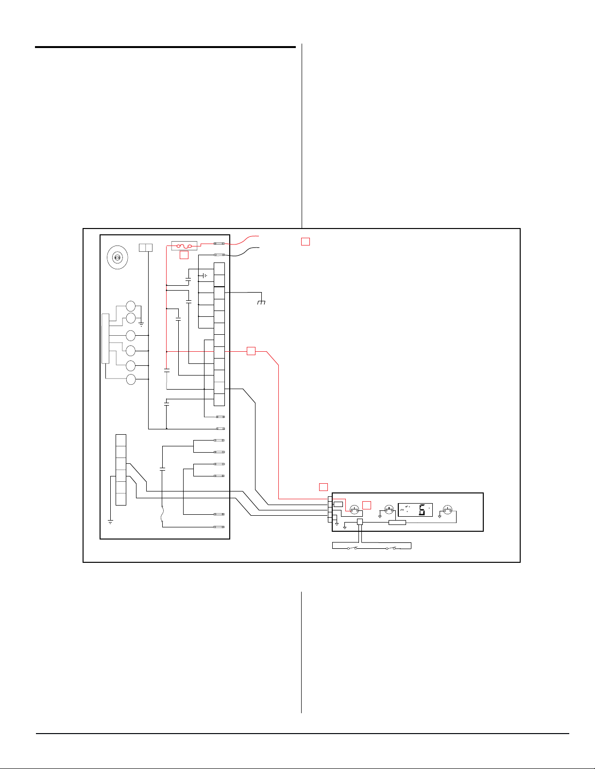
Switched 12-Volts (See Fig. 15):
Pressing the On-Off switch [E] will allow 12VDC to pass through
the On-Off switch and back to the Power Board via the blue wire [F]
connected between the Display Board at P1-3 [G] and the Power
Board at P2-3 [H]. Once the 12VDC reaches the Power Board, a
signal is sent out to the coil of relay K3 [J] via the U1 microprocessor. This signal allows the K3 relay to energize thus closing the
normally open contacts [K].
www.norcold.com
15
SERVICE MANUAL
Fault Codes, cont’d.
NOTICE
NOTICE
2
P3
1
J
K3
K1
K4
U1
K5
K2
K6
WH-BK/BC-NR
1
2
H
35
4
6
P2
POWER BOARD/PANNEAUD’ALMENTATION
BK-NR
BU-BL
K3
K
K1
K2
F2 8-Amp
F1 5-Amp
K5
F
12VDC
GND
12
P4
K6
-
125
K4
-
-
3
-
4
12VDC/VCD (BAT POS)
12VDC/VCD (BAT NEG)
YL-GN/JN-VE
+
+
67
+
+
8
+
9
+
10
P1
+
LIMIT_OUT
LIMIT_IN
AC_HT_HI_2
AC_HT_HI
AC_HT_LO_2
AC_HT_LO
L
RD-YL/RG-JN
BU-BL
BK-NR
G
P1
1
ON-OFF
Vreg
2
3
4
5
MODE
E
P3
MICRO
DISPLAY BOARD /
TEMP
CARTE D’AFFICHAGE
RD-BU/RG-BL
L2
L1
RD-YL/RG-JN
M
NOR000241A
Fig. 15 - Switched 12 Volts
K3 is a latching relay. Once the relay
coil is energized the contacts close and
remain closed even when the 12VDC is
removed, hence the term “latching relay”.
With the K3 contacts now closed, 12VDC
is passed back to the Display Board via
the red-yellow wire [L] between P1-9 of
the Power Board and P1-2 [M] of the
Display Board. This 12VDC will remain at
P1-2 [M] until the latching relay is “unlatched”, which will not take place until the
On-Off button is depressed again. This
12VDC is termed the switched 12-volts
and is used to power ON the display.
The On-Off switch [E] is a momentary
push- button switch. The operation de-
scribed above takes place during the “split
second” the On-Off button is depressed
to power the refrigerator on. If for some
reason the display does not turn on, the
On-Off button can be pushed and held
down to aid in troubleshooting. EXAMPLE:
Verify you have 12VDC between P1-1
(GND) and P1-6 (continuous 12-volts) of
the Power Board. Leave the meters black
ground lead connected to P1-1 and move
the red positive lead from P1-6 to P2-3 of
the Power Board. Have someone press
and hold the On-Off button. You should
measure 12VDC as long as the On-Off
button is held in. When the On-Off button
is released you should see the 12VDC go
away.
2118, 2118IM, 2118IMD Series
16
www.norcold.com
Fault Codes, cont’d.
no AC
WITH BEEPING
ALARM
code
NOR000124A-noac
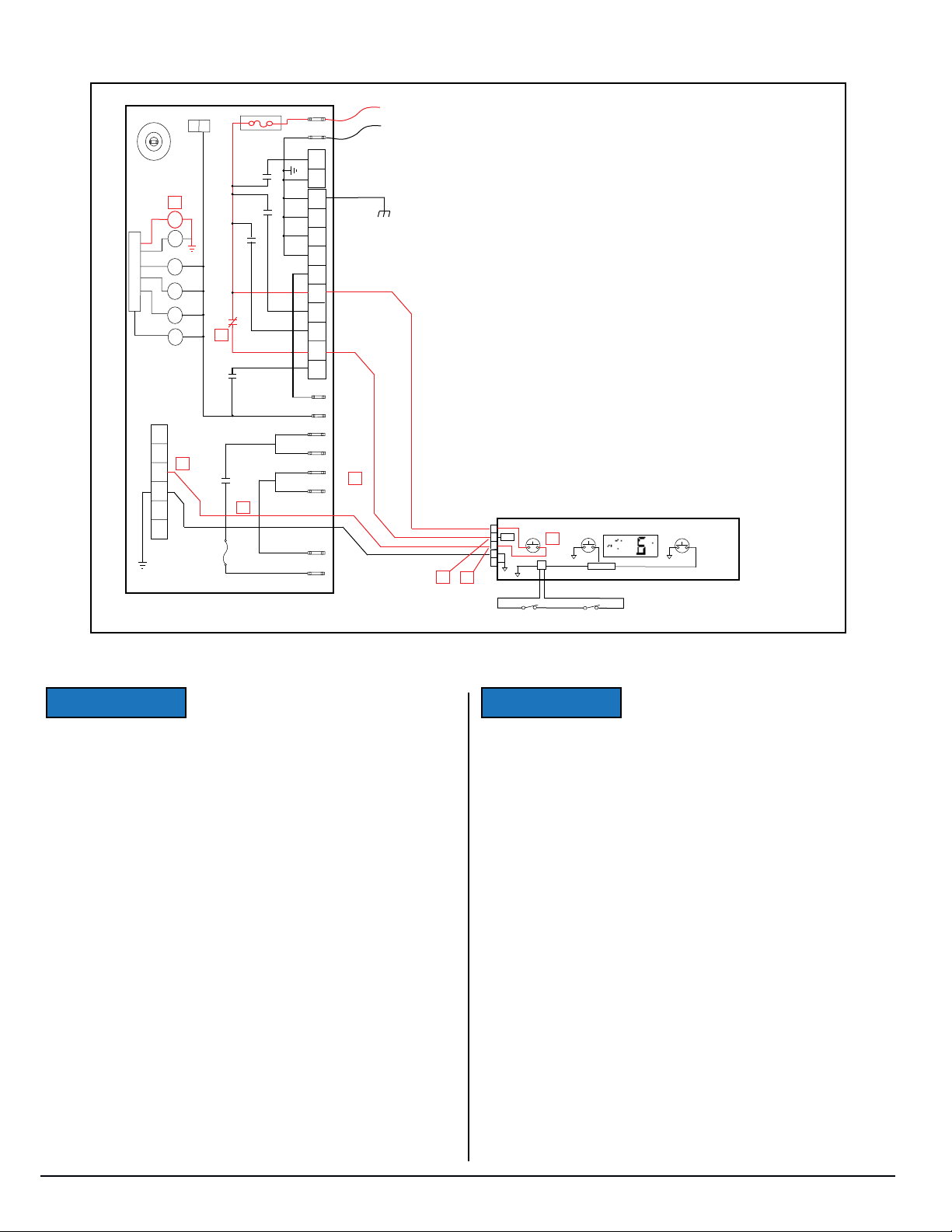
Meaning:
The Power Board sensed the refrigerators AC input voltage to be
less than 85 volts. This fault, by itself, can only be displayed while
operating in the Manual AC Mode. This fault can be displayed in
conjunction with other faults while operating in the Auto Mode. For
example; no AC followed by no FL (See AUTO mode discussion for
further explanation).
Verify:
■ The refrigerator is plugged into a known working AC outlet sup-
plying a minimum of 85 VAC.
■ The AC power cord is in good operating condition.
■ The glass 8-amp fuse (F2) on the Power Board is intact.
Potter & Brum
T7CS1D2-05
5VDC
05
700514
5A@120VAC
CH
F2
code
code
WITH BEEPING
ALARM
no FL
WITH BEEPING
ALARM
code
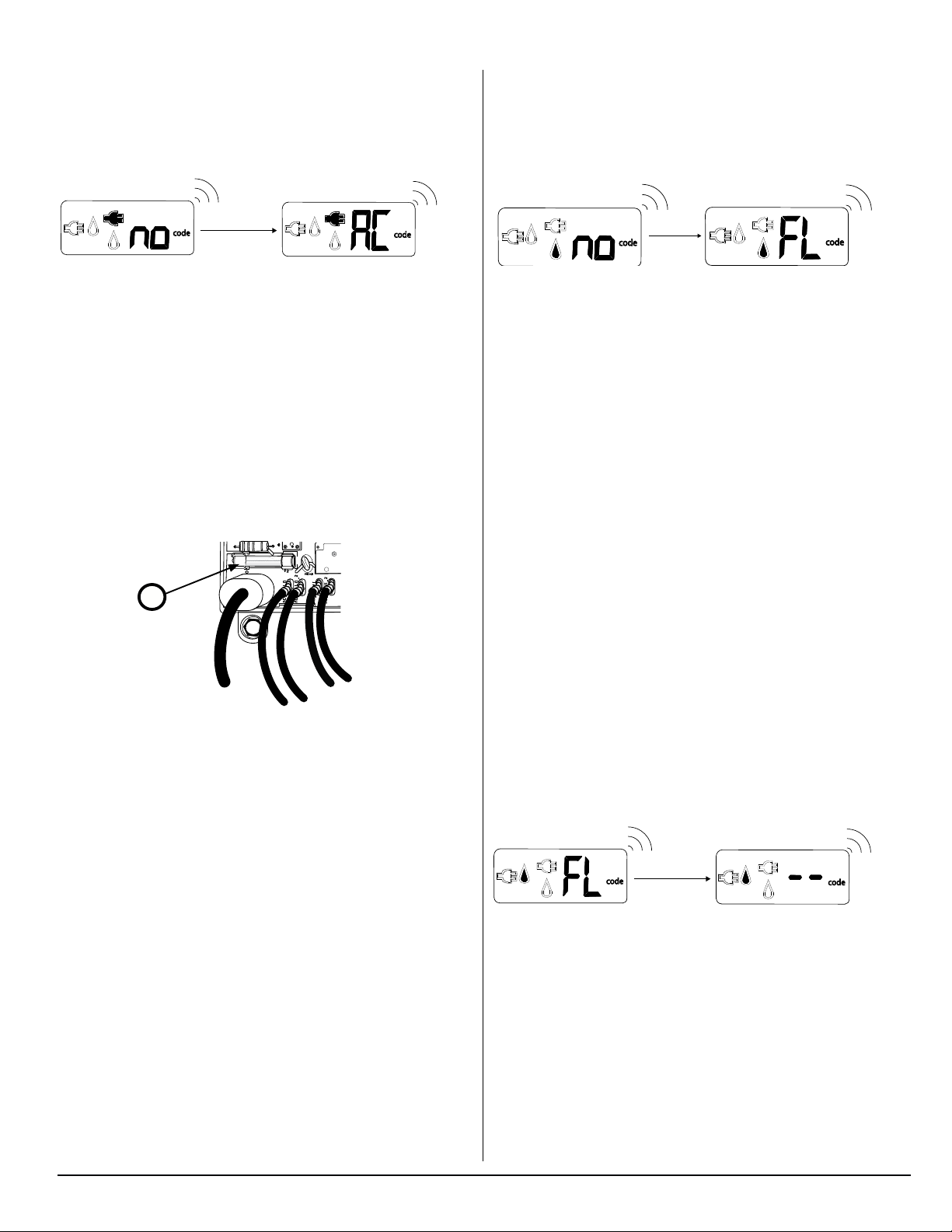
Meaning:
The Power Board was not able to detect a ame present at the
burner. This fault, by itself, can only be displayed while operating in
the Manual Gas Mode. This fault can be displayed in conjunction
with other faults while operating in the Auto Mode. For example; no
AC followed by no FL.
Verify:
■ All propane gas shutoff valves (including manual shutoff on gas
valve itself) are open.
■ Propane Gas pressure at refrigerator is 10.5 in. W.C - 11.5 in.
W.C. (water column).
■ Propane gas supply line is free of air.
■ The burner is clean.
■ The electrode-to-burner air gap is between 1/8” and 3/16”.
■ The spark-sense igniter wire is installed correctly and in good
operating condition.
■ Gas valve solenoid is in good operating condition (Coil resis-
tance ≈ 74 Ohms to 92 Ohms).
■ Wires to the gas valve are connected and in good operating
condition.
■ Power Board supplies 12 VDC to gas valve when required.
■ If the above steps all check good, replace power board.
code
code
WITH BEEPING
ALARM
NOR0002142A
NOR000298A
■ The (F2) fuse holder clips are not loose or broken.
■ If above steps all check good, replace power board.
FL --
WITH BEEPING
ALARM
code
NOR000124A---
Meaning:
The gas valve is “mechanically” stuck open and subsequently the
Power Board has sensed a ame present when there should not
be. This fault can be displayed in ANY MODE.
■ Replace the gas valve.
code
code
WITH BEEPING
ALARM
www.norcold.com
17
SERVICE MANUAL
Fault Codes, cont’d.
no AC, no FL
WITH BEEPING
ALARM
code
WITH BEEPING
ALARM
code
NOR000124A-noac_no
Meaning:
This fault is a combination of two separate faults. First, the Power
Board sensed the AC input voltage to be less than 85VAC and
automatically switched to the LP Gas Mode. Secondly, the Power
Board was then unable to detect a ame while operating in the
Auto Gas Mode. This fault can only be displayed while operating in
the Auto Mode.
Verify:
■ Follow the “Verify” instructions for the “no AC” fault and “no FL”.
■ If all the steps listed under Verify the “no AC” and the “no FL”
codes check good, replace power board.
code
code
code
code
WITH BEEPING
ALARM
WITH BEEPING
ALARM
AC HE
WITH BEEPING
ALARM
code
036
NOR000124A-ache
Meaning:
The Power Board sensed the AC heater current to be too low. This
fault can only be displayed while operating in the Manual AC Mode.
Verify:
■ AC heater connections are in good repair and are properly
connected to the Power Board. (Refer to Fig. 17 and Fig. 18
refrigerator wiring diagrams for proper connection.)
■ AC heater resistance measures between 45Ω and 51Ω:
■ No - replace AC heater.
■ Contact Customer Service for further instructions.
code
code
WITH BEEPING
ALARM
oP LI
code
WITH BEEPING
ALARM
NOR000124A-opli
code
code
WITH BEEPING
ALARM
AC rE
WITH BEEPING
ALARM
code
NOR000124A-acre
Meaning:
The AC heater relay contacts of relay K2, on the Power Board, are
stuck closed. This fault can be displayed in ANY MODE.
■ Replace the Power Board.
2118, 2118IM, 2118IMD Series
code
code
WITH BEEPING
ALARM
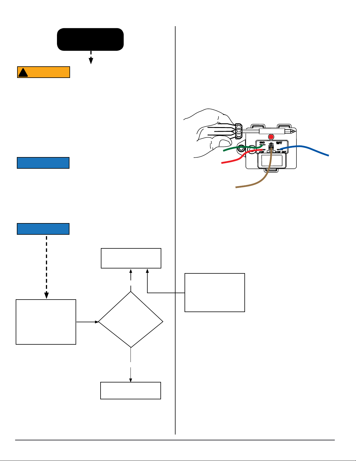
Meaning:
Refer to the flow chart(s) that are on the next four (4) pages.
18
www.norcold.com
Fault Codes, cont’d.
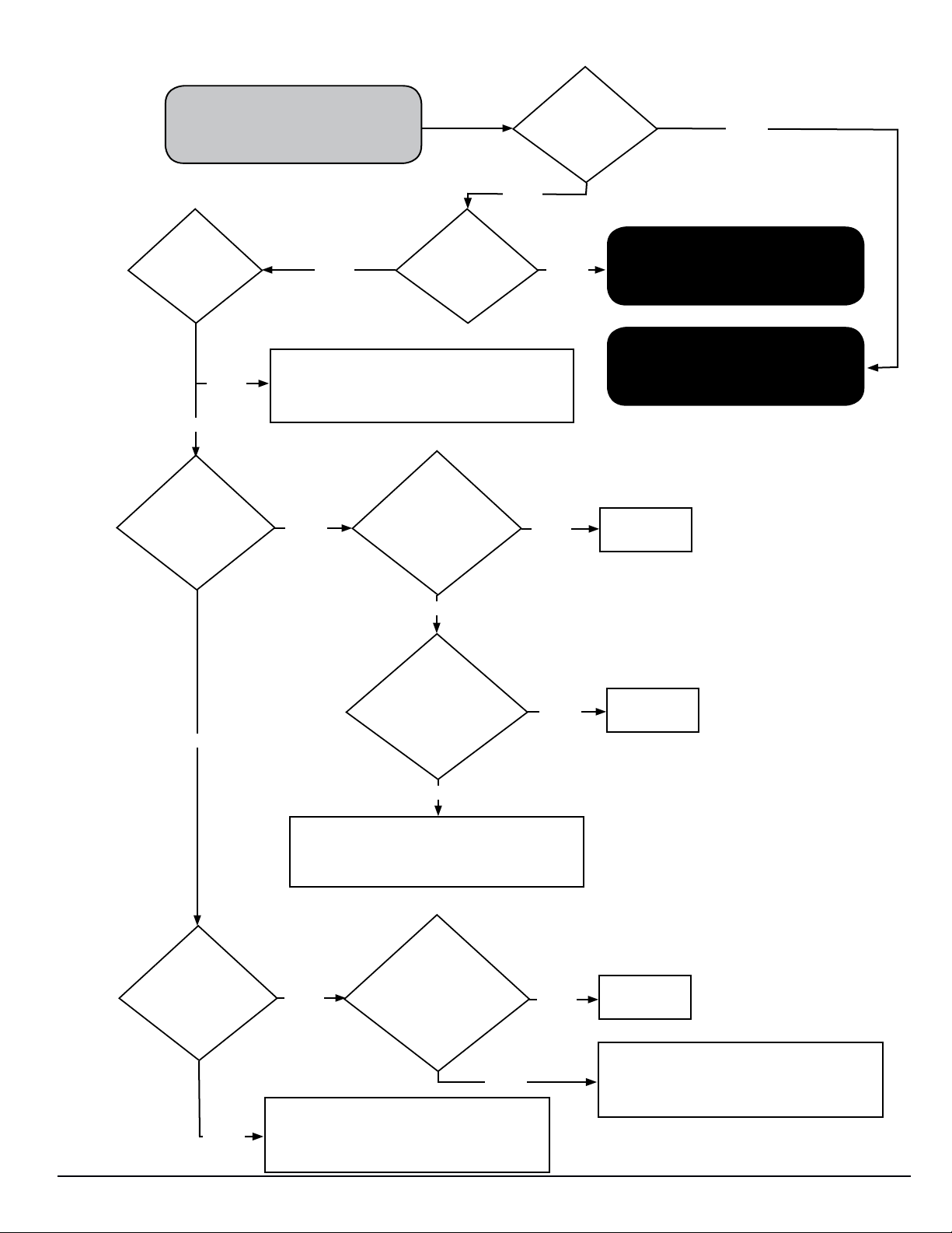
“LI” “oP” fault code is displayed
on front of refrigerator.
BEGIN
Is
TMC
wired
according to
the wiring diagram/
schematic?
1. Connect or repair connections as needed.
2. If oP LI code clears, the repair is complete.
No
3. If oP LI code remains return to BEGIN process
on this owchart.
Yes
Is there
12 VDC
between the GND
and +12V terminals of
the TMC?
Yes
Is TMC
red light
ashing?
Is there
12 VDC
between the GND
and +12V OUT termi-
nals of the TMC?
Is TMC
red light on
solid? (Tempera-
ture Monitor Control)
No
YesNo
No
Yes
A
Go to TMC RED LIGHT FLASHING on
next page.
B
Go to TMC RED LIGHT SOLID on
page 21.
Replace the
TMC
No
Is there
12 VDC
between the GND
and +12V terminals of
the TMC?
Yes
Yes
Re-
move power
board cover. Is
there 12 VDC between
the TMC GND terminal and
power board LIMIT_IN
terminal?
No
1. Repair blue limit in wire and/or connections as
needed.
2. If oP LI code clears, the repair is complete.
3. If oP LI code remains, return to BEGIN pro-
cess on this owchart.
Remove
power board
cover. Is there 12
No
VDC between the gas valve
bracket and power board
LIMIT_OUT
terminal?
Yes
1. Repair green ground wire and/or connections
as needed.
2. If oP LI code clears, the repair is complete.
3. If oP LI code remains, return to BEGIN pro-
cess on this owchart.
Yes
No
Replace
Power board
Replace
Power board
1. Repair red limit out wire and/or connections
as needed.
2. If oP LI code clears, the repair is complete.
3. If oP LI code remains, return to BEGIN pro-
cess on this owchart.
www.norcold.com
19
SERVICE MANUAL
Fault Codes, cont’d.
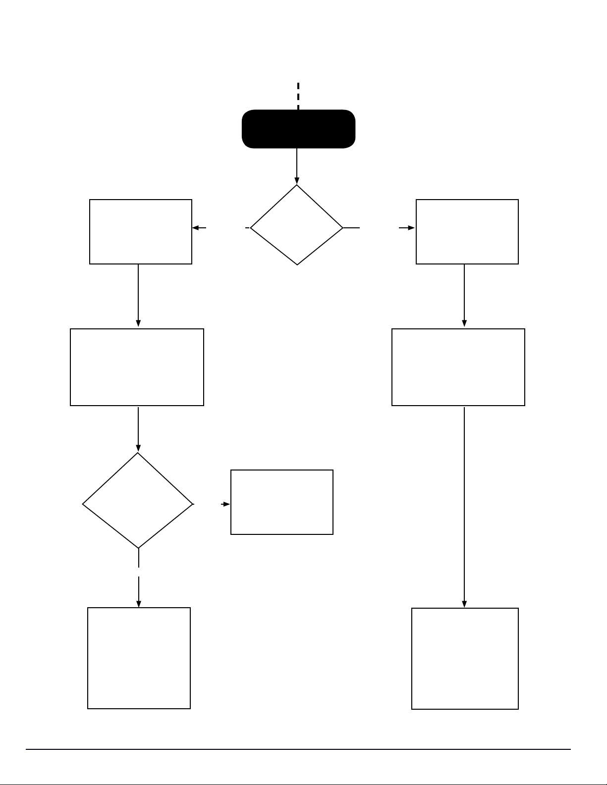
Temperature Monitor Control (TMC) - Red Light Flashing
A
From Previous Page
FAST
On/Off 2 to 3 times per
second
The TMC has sensed an open
circuit in the thermocouple circuit
Is thermocouple
plugged into T/C
connector of TMC?
FAST SLOW
Is red light
ashing FAST or
SLOW?
Yes
Replace thermocouple
SLOW
On/Off once per second
The TMC has sensed the input
voltage to be below 9.5 VDC
Plug in thermocouple.
Once plugged in, TMC
will self-recover and
oP LI fault code will be
2118, 2118IM, 2118IMD Series
No
cleared.
20
Make sure input voltage
to TMC +12V terminal is
between 10.5 –15.4 VDC.
Once input voltage is
above 10.0 VDC, High
Temperature Monitor will
self-recover and oP LI
fault code will be cleared.
www.norcold.com
Fault Codes, cont’d.
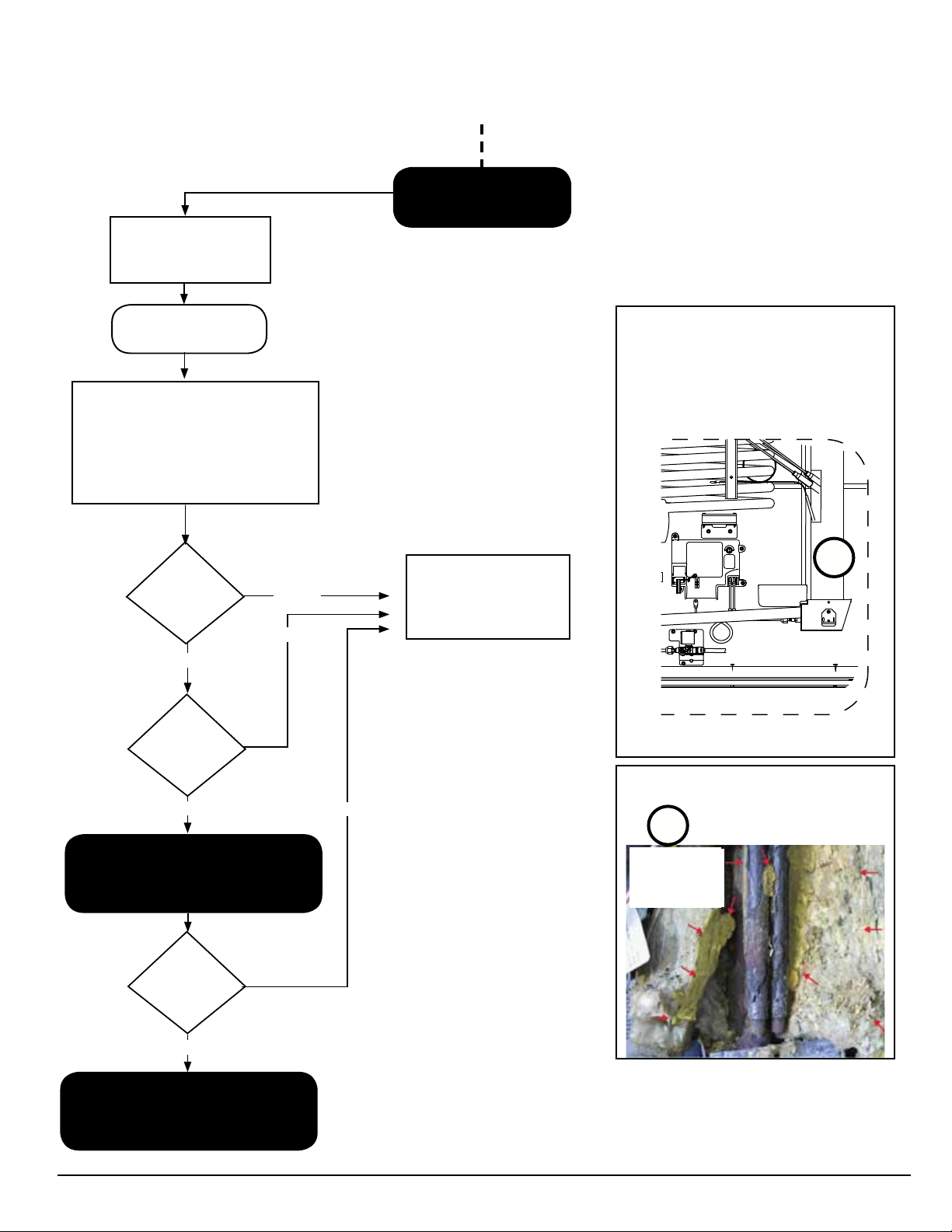
Temperature Monitor Control (TMC) - Red Light on Solid
B
From Previous Page
Red light on TMC is
ON solid
Inspect for cooling unit
1. Carefully remove insulation canister
and insulation from around boiler
(A).
2. Visually inspect exposed boiler area
for any powdery, yellow residue
indicating leaking chromate (B).
3. Smell around boiler area for
ammonia.
powdery residue
leak.
Is yellow,
visible?
Yes
Yes
No
Can you
smell ammonia?
Removing Insulation
1. Remove the insulation canister (A) and
remove the insulation.
A
REPLACE COOLING
UNIT
NOR000212A-1
2. Inspect for powdery, yellow residue (B).
No
Using litmus paper, inspect boiler area
for leaks.
Did litmus
paper indicate a
leak?
No
C
Go to TMC Lockout State on next
www.norcold.com
page.
Yes
21
Example of Chromate Leaking
B
Red arrows
pointing to yellow,
powdery residue indicates chromate
leak
SERVICE MANUAL
Fault Codes, cont’d.
WARNING
NOTICE
NOTICE
C
From Previous Page
Do not attempt this TMC validation unless
!
ATTENTION
Clear the Temperature Monitor Control (TMC) Lockout
State
Clear the TMC lockout state (red light ON solid) shown below to
validate TMC functionality. The TMC is the black box control portion of the High Temperature Monitor System.
1. Red light of the TMC is ON (solid).
2. The boiler area of the cooling unit (where the thermocouple
is mounted) has cooled to less than 250° F.
3. A magnet has been positioned as shown in Fig. 16 for ve
(5) seconds.
you have already followed the “TMC Red
Light On Solid” instructions and deter-
mined that the cooling unit does not have
a leak. Otherwise, there is a serious risk
of re that can result in property damage,
personal injury, or death.
In order to clear the lockout state (red light
ON solid), the conditions below must be
met. DO NOT remove the plastic cover of
the TMC.
If lockout state does not clear in ve (5)
seconds, try using a stronger magnet.
Fig. 16 - Magnet position
+12V
634677
T/C
GND
REV E
YELLOW
+12V OUT
NOR000249A
REPLACE COOLING
UNIT
No
Once the TMC lockout
state has been cleared:
1. Run the refrigerator in
AC mode.
2. Monitor operation for
24 hours.
Did the refrigerator cool
properly?
Yes
REPAIR COMPLETE
■ Once the lockout state has been cleared, the red light of the
TMC will turn off.
■ If the refrigerator is not on, turn it on to further validate the TMC
conguration.
Repeated lockouts (red
light ON solid) indicate
potential cooling unit
failure - CONTACT
TECHNICAL SUPPORT
2118, 2118IM, 2118IMD Series
22
www.norcold.com
Fault Codes, cont’d.
WARNING
Sr
WITH BEEPING
ALARM
code
NOR000124A-5r
Meaning:
The Power Board detected an internal fault. This fault can be reset
by powering the refrigerator OFF and back ON. Should this fault
continue to be displayed after being reset, the Power Board should
be replaced. This fault can be displayed in ANY MODE.
Verify:
■ Igniter Spark Sense electrode is not touching the burner
(shorted to ground).
■ Wire from P1-10 (12VDC out to gas valve) is not shorted to
ground.
■ For example, if the wire were to be pinched somewhere and
the insulation covering torn, this would allow the bare wire to
short to ground and this fault will be displayed.
■ If the above steps check good and this error continues, replace
the power board.
Lo dc without alarm while in GAS Mode
WITH BEEPING
ALARM
code
NOR000124A-lodc-woalarnGAS
Meaning:
The refrigerator attempted to ignite or re-ignite the burner when the
DC input voltage was less than 10.0 VDC. The gas valve/igniter
outputs are inhibited when there is a call for cooling and the DC
voltage is less than 10.0 VDC. Should there be a call for cooling
while the DC input voltage is greater than 10.0 VDC and the DC
input voltage then falls below 10.0 VDC, the gas valve will remain
energized and no fault will be displayed. This fault will automatically
reset and the gas valve/igniter outputs will be allowed to operate
once the DC input voltage is >10.5 VDC. This fault can only be
displayed in the Auto and Manual GAS modes.
Verify:
■ That the battery charging equipment of the vehicle is opera-
tional.
■ That the AC/DC converter is operational (if applicable).
■ Contact Customer Service for further instructions.
code
code
WITH BEEPING
ALARM
Lo dc with alarm
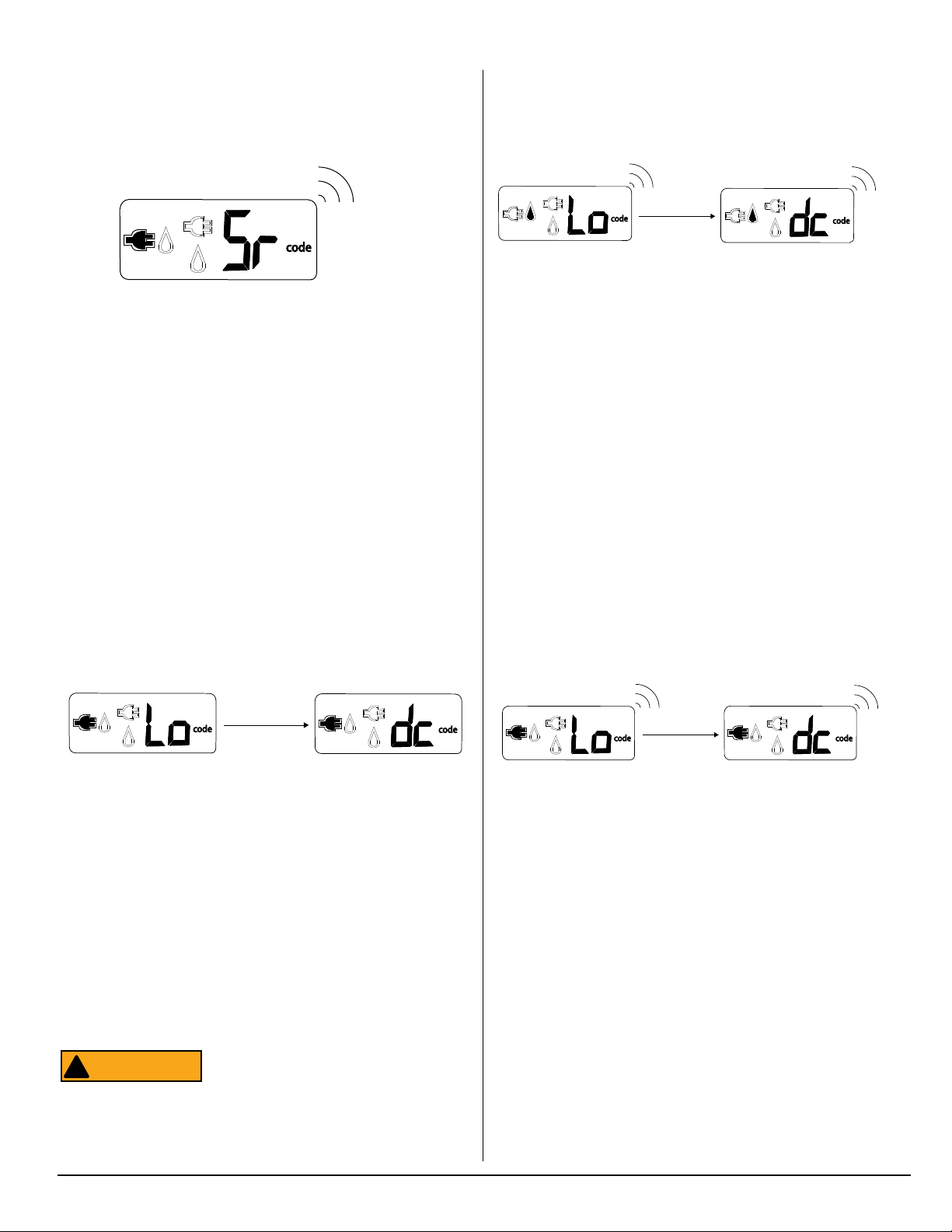
Lo dc without alarm
code
Meaning:
The Power Board has determined the DC input voltage is less than
10.5 VDC. Anytime the DC input voltage falls below 10.5 VDC and
the low DC voltage fault is displayed the divider, perimeter, and
apper heaters are turned OFF. This fault can be displayed in ANY
MODE. This fault will be cleared and the divider, perimeter, and
apper heaters will be turned back ON when the DC input voltage
is ≥11.5VDC.
Verify:
■ That the battery charging equipment of the vehicle is opera-
tional.
■ That the AC/DC converter is operational (if applicable).
■ If voltage is within range, replace power board.
Remember that the fault can not be
!
ATTENTION
cleared until the DC input voltage is
≥11.5VDC.
code
code
NOR000124A-lodc-woalarn
code
WITH BEEPING
ALARM
code
code
WITH BEEPING
ALARM
Meaning:
The DC voltage to the refrigerator is less than 8.5 volts DC. All
outputs are inhibited. This fault will automatically reset and outputs
will be allowed to operate once the DC input voltage rises above
9.0 VDC. This fault can be displayed in ANY MODE.
Verify:
■ That the battery charging equipment of the vehicle is opera-
tional.
■ That the AC/DC converter is operational (if applicable).
■ If voltage is within range, replace power board.
www.norcold.com
23
SERVICE MANUAL
Fault Codes, cont’d.
WITH BEEPING
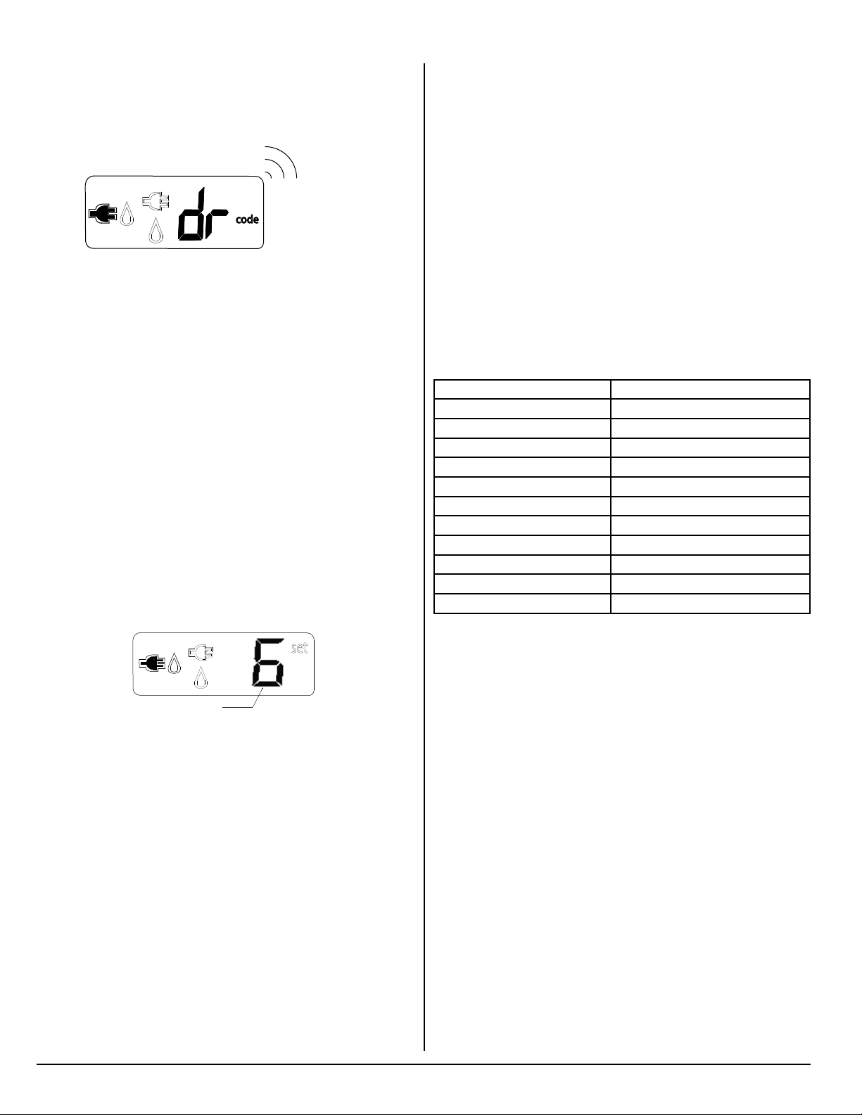
dr
ALARM
code
Meaning:
This fault indicates the optical display board has sensed that one
or both of the fresh food doors have been open for more than
2-minutes. If this fault is displayed, the fresh food interior light will
automatically be turned off. Once both doors are closed, the fault
code will be cleared and the interior light will be allowed to operate.
This fault can be displayed in any mode of operation.
Verify:
■ Both fresh food doors are latching when closed. Adjust the
strike plate if needed.
■ Both latches are operating correctly. Fix or replace handle latch
if necessary.
■ Both doors are aligned correctly. Align doors if necessary.
■ Both doors are not damaged or warped. Replace door if neces-
sary.
■ Light switches turn off light when held closed. If not, replace
switch.
■ Check for worn hinge bushings. Replace if necessary.
■ Check for bent bottom hinges. Replace if necessary.
Flashing temperature setting icon
length of time the heat source outputs (AC heater and propane gas
burner) are energized. The duty cycle, or length of time the cooling cycle is regulated, can be manually controlled via the TEMP
SET button. When a colder temperature is desired, changing the
temperature setting to the next “colder” setting will provide addi-
tional cooling by lengthening the cooling cycle. For example, if the
temperature setting is set to 5, adjusting the temperature setting to
the next colder setting of 6 will lengthen the cooling cycle. When a
warmer temperature is desired, changing the temperature setting
to a warmer setting shortens the cooling cycle. For example, if the
temperature setting is set to 4, lowering the setting to 3 will shorten
the cooling cycle.
Verify:
■ The fresh food n thermistor is plugged in and that the connec-
tions are not dirty or broken.
■ Thermistor resistance (Check resistance at thermistor connec-
tor with thermistor packed in ice bath).
Temperature* (°F) Resistance* (k Ω)
85 8.1 - 9.0
80 9.1 - 10.0
75 10.1 - 11.0
70 11.1 - 12.0
60 12.1 - 13.0
50 15.5 - 16.5
40 22.5 - 23.5
35 24.5 - 25.5
33 28.5 - 29.5
32 30.0 - 32.0
* Approximate values
set
NOR000243A
Flashing Temperature Setting ICON
A Flashing Temperature Display means the electronic controls
have sensed the n thermistor to be inoperable. This fault is only
displayed while the optical display is “awake.” To “wake” the display
press and release either the Mode or Temp Set buttons. If there is a
problem sensed with the thermistor the temperature setting icon will
ash ON and OFF. After 10-seconds the control will revert back to
the “sleep” mode. This fault can be displayed in ANY MODE.
Should the thermistor be sensed inoperable the electronic controls
will ignore the thermistor and revert to a BOS mode (Backup Operating System). The BOS mode is an electronically controlled duty
cycle that allows the refrigerator to continue operating until such
time the thermistor can be repaired or replaced.
This duty cycle will maintain refrigerator cooling by controlling the
■ An alternate method would be to use an infrared gun to
measure the n temperature. Then compare that temperature with the temperature indicated on Diagnostic Screen
#3. The temperature difference should be 6° F or less. If
not, thermistor is bad.
2118, 2118IM, 2118IMD Series
24
www.norcold.com
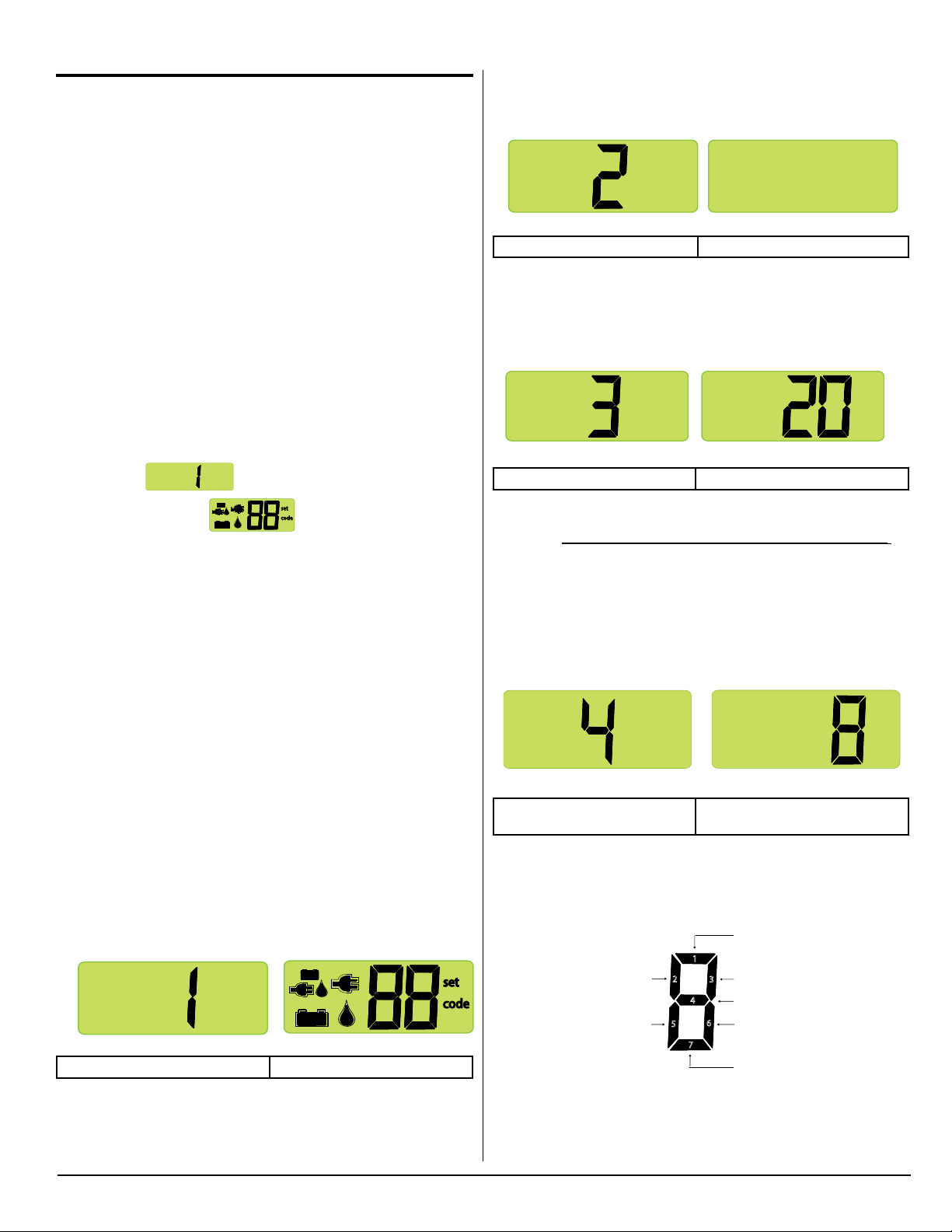
Diagnostic Mode
Individual segment identification:
The diagnostic mode is a tool incorporated within the controls
and can be accessed via the optical display. This tool is designed
to assist in verifying temperature, inputs, outputs, and to retrieve
recorded faults stored by the controls by displaying the various
information via the LCD. Ten (10) screens, each having a particular
function, are used to display this information. For example, screen
three (3) displays the fresh food n thermistor temperature, and
screens four (4) and ve (5) display stored fault history.
Screen 2. All Diagnostic Icons OFF
Press the MODE button to bring up screen 2.
NOR000125A-2
The LCD utilizes a dual 7-segment display within the LCD. The
screen number is displayed utilizing the left-side 7-segment dis-
play while inputs, outputs, and various fault related information is
displayed utilizing individual segments of the right-side 7-segment
display. These individual segments will be dened/explained under
each of the individual screen descriptions to follow.
Access Diagnostic Mode
1. Press and hold both the MODE and the Temperature Set buttons at the same time.
2. Release the MODE and the Temperature Set buttons as soon
as screen
3. A few seconds later,
displays.
set
code
displays.
Change Screens
To change screens, press and hold the MODE button until the next
screen displays.
Exit Diagnostic Mode
Screen 2 (Initial view) Screen 2 (Second view)
Screen 2 veries all icons are operational by turning them off
Screen 3. Fresh Food Fin Temperature
Press the MODE button to bring up screen 3.
NOR000125A-3
Screen 3 (Initial view) Screen 3 (Second view)
Screen 3 displays the actual n temperature being sensed by the
thermistor. This is not the fresh food cabinet air temperature.
The example shows the n temperature to be 20°F.
■ If the thermistor is “open”, the second view will show “00”.
■ If the thermistor is “shorted”, the second view will show “99”.
Screen 4. Stored Fault History
Press the MODE button to bring up screen 4.
4. Press and hold both the MODE and the Temperature Set but-
tons at the same time.
5. Release the MODE and the Temperature Set buttons when the
mode icons and temperature setting once again display.
Turning the refrigerator OFF then back ON also exits the Diagnostic Mode.
Screens and Diagnostic Segments Information
Screen 1. All Diagnostic Icons ON
NOR000125A-1-1
Screen 1 (Initial view) Screen 1 (Second view)
Screen 1 veries all icons are operational by turning them on.
set
code
NOR999125-4
Screen 4 (Initial view) Screen 4 (Second view)
All segments shown as being on.
Screen 4 displays stored fault history using lighted LED segments.
Refer to illustration below for fault history denitions of the indi-
vidual LED segments. If a fault occurred, its assigned fault history
Ignition Fault
1
Door Ajar
AC mode selected
but not available
2
3
DC voltage low
4
DC voltage high
6
5
7
AC relay stuck closed
AC heater failed open
www.norcold.com
25
SERVICE MANUAL
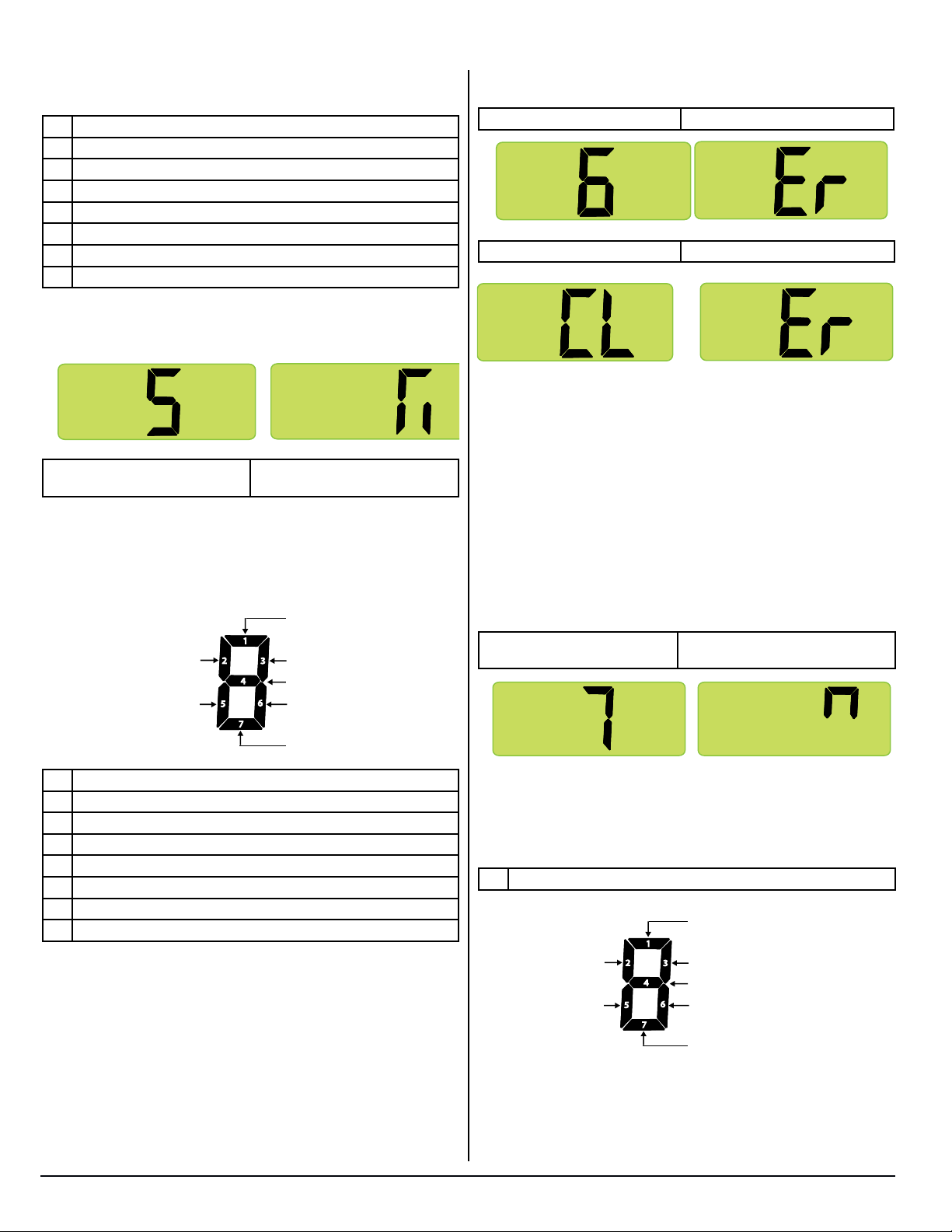
Diagnostic Mode, cont’d.
LED segment will be on.
Individual Segment Identification
1 Ignition fault.
2 Door ajar.
3 DC voltage low.
4 DC voltage high.
5 AC mode selected but not available.
6 AC relay stuck closed.
7 AC heater failed open.
Screen 5. Stored Fault History
Press the MODE button to bring up screen 5.
NOR000125A-5
Screen 5 (Initial view) Screen 5 (Second view)
All segments shown as being on
Screen 5 also displays stored fault history using lighted LED segments. Refer to illustration below for fault history denitions of the
individual LED segments. If a fault occurred, its assigned fault
history LED segment will be on.
Thermistor failure
1
Flame present
with gas off
Service required
error has occured
2
3
Not used
4
5
7
Not used
6
AC voltage has been high
Not used
Press the MODE button to bring up screen 6.
Screen 6 (Initial view) Screen 6 (Second view)
NOR000125A-6
Screen 6 (Third view) Screen 6 (Fourth view)
Screen 6 provides a way to erase fault history from memory. To
erase the fault history:
■ Press and hold the Temperature Set button (approximately ve
(5) seconds) until “CL” shows on the screen.
■ Once “CL” is displayed, release the Temperature Set button.
■ Press and hold Temperature Set button (approximately ve (5)
seconds) until “Er” is displayed again. At this point, the fault history has been cleared on both Screen 4 and Screen 5.
Screen 7. Power Board Inputs
Press the MODE button to bring up screen 7.
Screen 7 (Initial view) Screen 7 (Second view)
All segments shown as being on
NOR000125A-7
Individual Segment Identification
1 Thermistor failure.
2 Flame present with gas off.
3 Not used.
4 Not used.
5 Service required error has occurred.
6 AC voltage has been high.
7 Not used.
Screen 6. Erasing Fault History
2118, 2118IM, 2118IMD Series
Screen 7 displays “live” power board inputs using lighted LED
segments. Refer to illustration below for “live” input denitions of
the individual LED segments. If a power board input is active or
“live,” its assigned input LED segment will be on.
Individual Segment Identification
Food compartment light
is off and door is closed
1
Flame is sensed
Not used
26
2
3
Thermistor is sensing fin temperature
4
Not used
6
5
7
Not used
Not used
www.norcold.com
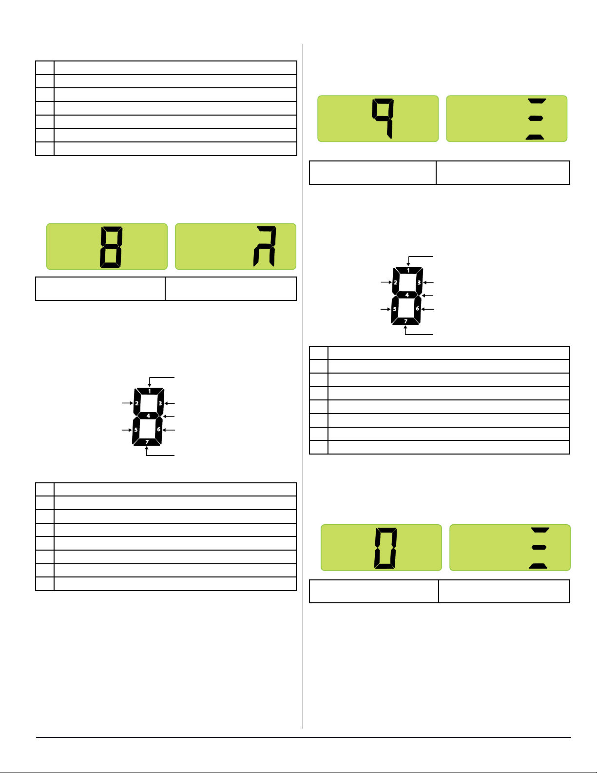
Diagnostic Mode, cont’d.
1 Food compartment light is off and door is closed.
2 Flame is sensed.
3 Thermistor is sensing fin temperature.
4 Not used.
5 Not used.
6 Not used.
7 Not used.
Screen 8. Power Board Outputs
Press the MODE button to bring up screen 8.
NOR000125A-8
Screen 8 (Initial view) Screen 8 (Second view)
All segments shown as being on
Screen 8 displays “live” power board outputs using lighted LED
segments. The following illustration provides denitions of the
“live” outputs indicated by the individual LED segments. If a power
board output is active or “live,” its assigned output LED segment will be on.
AC heater relay is energized
1
Not used
DC power to
light switch
2
3
DC power to divider heater
4
Gas valve relay is energized
6
5
7
DC power to ignition circuit
Not used
Screen 9. Power Board DC Input Voltage Status
Press the MODE button to bring up screen 9.
NOR000125A-9
Screen 9 (Initial view) Screen 9 (Second view)
All segments shown as being on
Screen 9 displays DC voltage status using lighted LED segments.
Refer to illustration below for denitions of the individual LED seg-
ments. If DC voltage at the power board is within normal range
(10.5 to 15.4 VDC), LED segment 4 will be on.
DC voltage higher than 15.4 volts
1
Not used
Not used
Individual Segment Identification
1 DC voltage higher than 15.4 volts.
2 Not used.
3 Not used.
4 DC voltage normal.
5 Not used.
6 Not used.
7 DC voltage lower than 10.5 volts.
2
3
Not used
4
DC voltage normal
6
5
7
Not used
DC voltage lower than 10.5 volts
Individual Segment Identification
1 AC heater relay is energized.
2 Not used.
3 DC power to divider heater.
4 Gas valve relay is energized.
5 DC power to light switch.
6 DC power to ignition circuit.
7 Not used.
www.norcold.com
Screen 0. Power Board AC Input Voltage Status
Press the MODE button to bring up screen 0.
NOR000125A-0
Screen 0 (Initial view) Screen 0 (Second view)
All segments shown as being on
Screen 0 displays AC voltage status using lighted LED segments.
Refer to illustration below for denitions of the individual LED seg-
ments.
27
SERVICE MANUAL
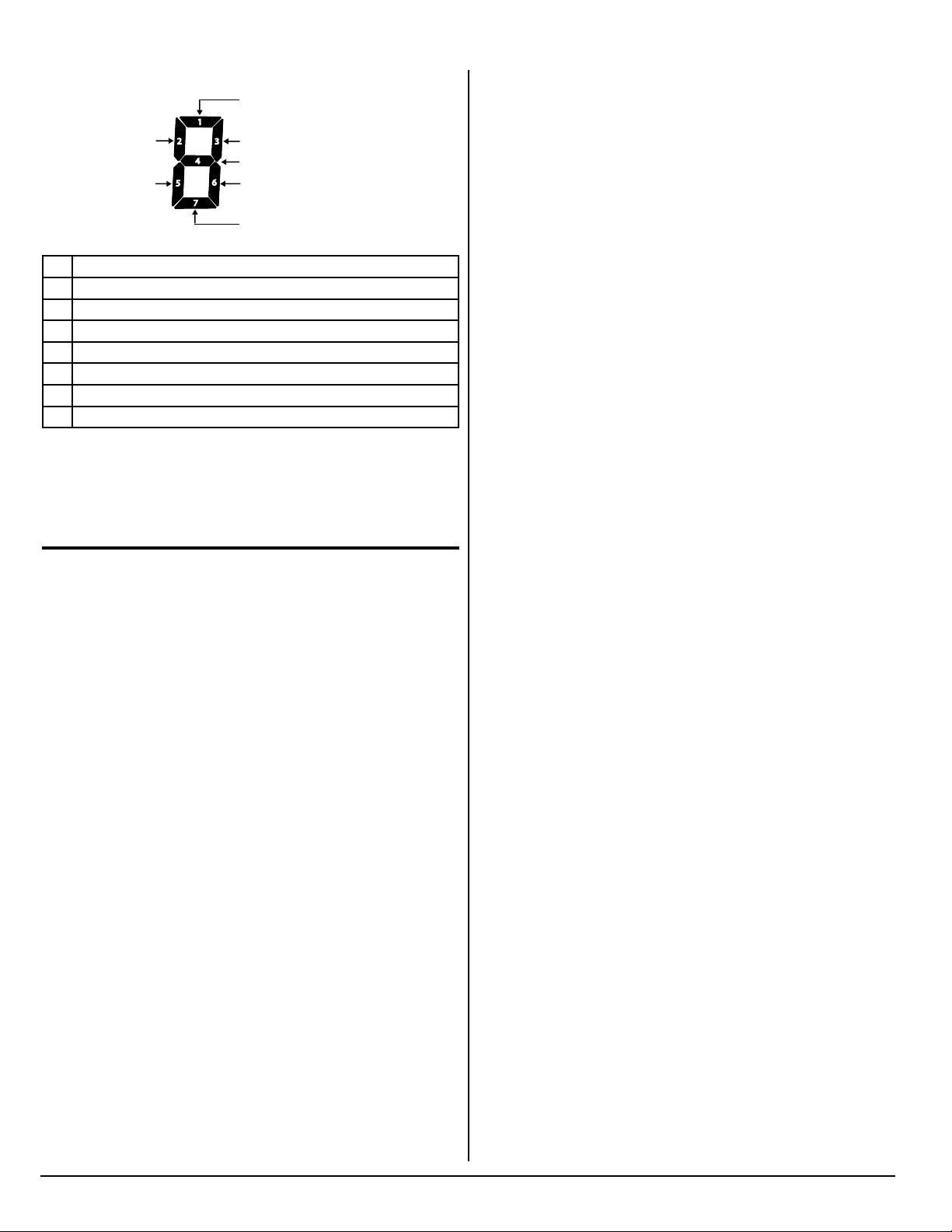
Diagnostic Mode, cont’d.
AC voltage higher than 132 volts
1
Not used
Not used
2
3
Not used
4
5
7
AC voltage normal
6
Not used
AC voltage lower than 85 volts
Individual Segment Identification
1 AC voltage higher than 132 volts.
2 Not used.
3 Not used.
4 AC voltage normal.
5 Not used.
6 Not used.
7 AC voltage lower than 85 volts.
If AC voltage at the power board is within normal range (108 to
132 VAC), LED segment 4 will be on.
Ice Maker
For information about ice maker operation and troubleshooting,
please refer to the separate Ice Maker Service document.
2118, 2118IM, 2118IMD Series
28
www.norcold.com
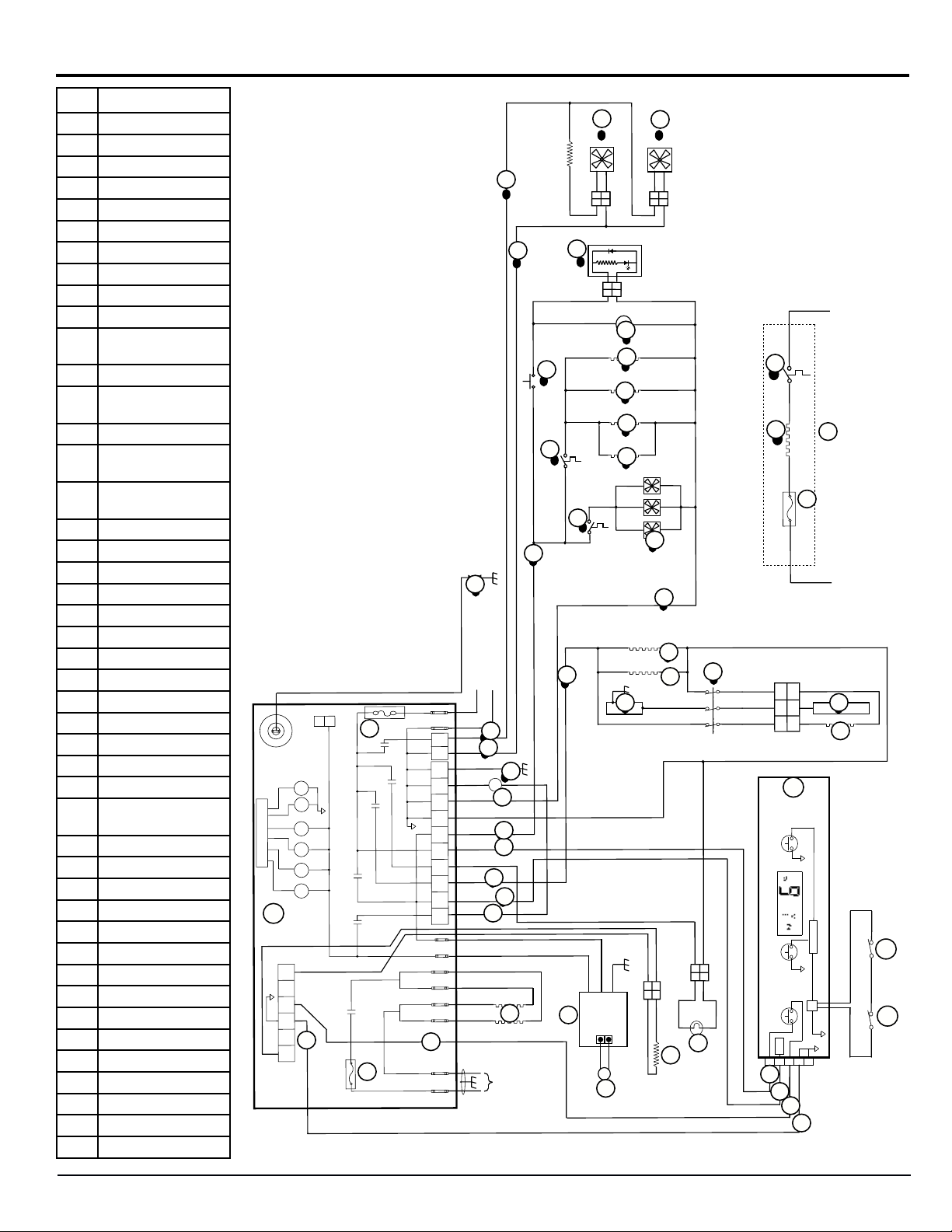
Wiring Diagram
Description
PB Power Board
DB Display Board
CW Cold Weather Kit
A AC Heaters
B Light
C Thermistor
D Gas Valve
E Divider Heater
F Perimeter Heater
G Fresh Food Blower
H Temperature Monitor
Control
I External Fans
J * Ice Maker Water Line
Heater
K * Water Valve Heater
L * Dispenser Water Line
Heater
M * Dispenser Water Valve
Heater
N * Water Valve
O * Dispenser Light P.C.B.
P * Dispenser Switch
Q Temperature Switch
R * Temperature Switch
S Divider Heater Housing
T Door Contacts
U Flapper Heater
V Flapper Housing
W Door Switch
X Igniter
Y Freezer Blower
Z Thermocouple
1 Fused Continuous 12
VDC
2 Switched 12 VDC
3 Communications
4 Display Ground
5 Auxiliary Ground
6 Auxiliary +12 VDC
7 Divider +12 VDC
8 Gas Valve +12 VDC
9 Internal Fans Ground
10 Internal Fans +12 VDC
11 Cooling Unit Heater
12 Temperature Switch
F1 5 Amp DC fuse
F2 8 Amp AC fuse
F3 3 Amp DC fuse
* Optional
www.norcold.com
NOR000186A
T1
U1
PB
BK-YL/NR-JN
P2
PB
2
P3
1
F1
K6
K3
K1
K4
K5
K2
K6
RD-BU/RG-BL
1
2
35
4
BU/BL
4
4
6
BK/NR
K4
K5
K3
K1
LIMIT_OUT
LIMIT_IN
AC_HT_HI_2
AC_HT_HI
K2
AC_HT_LO_2
AC_HT_LO
F2
Fig. 17 - Wiring Diagram
12VDC
GND
P4
P1
3
3
L2
L1
1
2
125
3
4
67
8
9
10
RD/RG
BK/NR
GN/VE
-
WH/BC
-
BK/NR
-
WH/BC
-
RD/RG
+
RD-BU/RG-BL
+
+
YL/JN
OR/OR
+
+
RD-YL/RG-JN
WH/BC
+
RD/RG
+
BU/BL
BK/NR
BK/NR
BK/NR
BK/NR
X
X
+12VDC
8
29
10
10
9
9
7
8
10
10
9
9
WH/BC
6
6
12VDC GROUND
D
D
5
5
6
6
1
1
7
2
2
8
A
A
120VAC
RD/RG
BK/NR
Y
Y
-
+
2
1
2
1
RD/RG
G
G
-
+
2
1
2
1
O*
O
2
1
2
1
N*
N
M*
P*
P
WH/BC
BR/BR
R*
R
BR/BR
Q
M
L*
L
K*
K
J*
J
RD/RG
RD/RG
Q
RD/RG
I
I
BK/NR
BK/NR
BK/NR
BK/NR
12
12
11
11
12VDC GROUND
BR/BR BR/BRBK/NR
cw
F3
BK/NR
+12VDC
5
5
F
F
7
7
S
S
RD-BU/RG-BL
GN/VE
RD/RG
BU/BL
+12V IN
H
H
+12V OUT
-
+
YL/JN
RD/RG
Z
Z
BK-YL/NR-JN
1
22
1
+
GND
-
T
E
C
T
E
YL/JN
WH/BC
2
1
2
1
-
+
B
B
C
RD-YL/RG-JN
1
1
V
V
2
2
3
3
U
U
DB
DB
TEMP
MICRO
MODE
P3
ON-OFF
Vreg
P1
2
4
1
5
3
1
1
BU/BL
RD-BU/RG-BL
BK/NR
2
2
3
3
4
4
YL/JN
VT/VT
W
OR/OR
W
W
W
SERVICE MANUAL
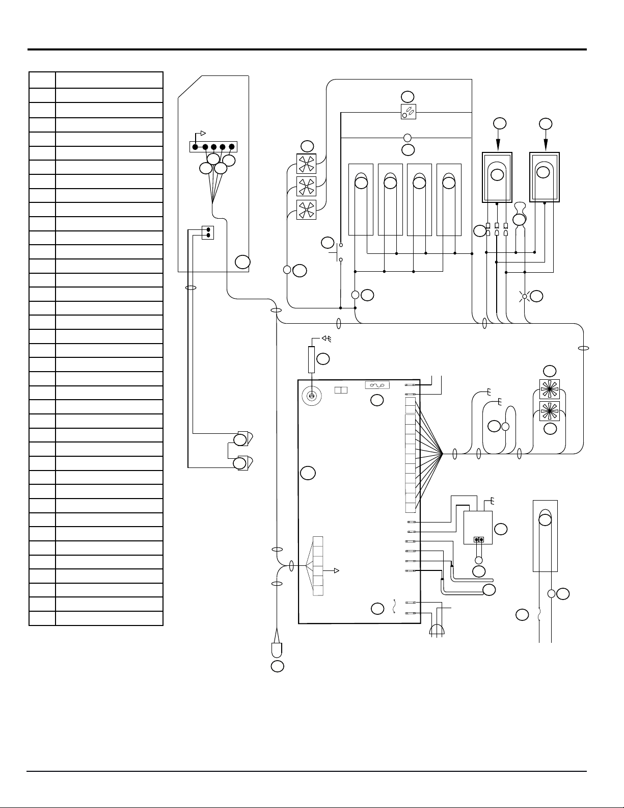
Wiring Pictorial
Description
PB Power Board
DB Display Board
A AC Heaters
B Light
C Thermistor
D Gas Valve
E Divider Heater
F Perimeter Heater
G Fresh Food Blower
H Temperature Monitor Control
I External Fans
J * Ice Maker Water Line Heater
K * Water Valve Heater
L * Dispenser Water Line Heater
M * Dispenser Water Valve Heater
N * Water Valve
O * Dispenser Light P.C.B.
P * Dispenser Switch
Q Temperature Switch
R * Temperature Switch
S Divider Heater Housing
T Door Contacts
U Flapper Heater
V Flapper Housing
W Door Switch
X Igniter
Y Freezer Blower
Z Thermocouple
1 Fused Continuous 12 VDC
2 Switched 12 VDC
3 Communications
4 Display Ground
11 Cooling Unit Heater
12 Temperature Switch
F1 5 Amp DC fuse
F2 8 Amp AC fuse
F3 3 Amp DC fuse
* Optional
P1-6
P1-5
2
NOR000187A
O*
O
V
V
P1-1
3
1
1
4
2
234
P3-2
P3-1
DB
DB
4
P2-3
P2-4
W
W
W
W
2
2
P2-6
P2-1
I
I
J* K* L*
J
N
N*
U
L
K
M*
M
U
F
T
+12VDC
12VDC GROUND
12
P1-3
P1-1
+12V OUT
YL/JN
Z
T
+12V IN
+
P1-8
GND
P1-4
5
GND
D
D
P1-2
P1-10
GND
H
H
-
RD/RG
Z
A
A
P*
P
Q
Q
R
R*
P1-6
P1-9
X
X
T1
PB
PB
1
2
35
4
4
6
P2
P1-5
2
+12VDC / +12VCC
2
P3
1
F1 5-Amp
F1
12VDC
GND
P4
P1
LIMIT_OUT
LIMIT_IN
AC_HT_HI_2
AC_HT_HI
AC_HT_LO_2
AC_HT_LO
F2
L2
F2 8-Amp
L1
12VDC GND / -12VCC
1
2
125
3
4
67
8
9
10
S
S
E
E
F
B
B
P1-7
7
Y
Y
G
G
P4-1
9 11
F3
P4-2
11
11
12
12
F3 3-Amp
2118, 2118IM, 2118IMD Series
C
C
Fig. 18 - Wiring Pictorial
30
+12VDC
12VDC GROUND
12VDC GROUND / -12VCC
+12VDC / +12VCC
www.norcold.com
 Loading...