

Norcold 1210, 1210ACIM, 1210ACIMD, 1210ACIMSSD, 1210ACSS Installation Manual
...
Installation Manual
!
!
for the 121X series of RV Refrigerators
The letter “X”, in the model numbers above, stands for a letter or numeral which means a
refrigerator option.
WARNING: Improper installation, adjustment, alteration, service or maintenance
can cause injury or property damage. Refer to this manual. For
assistance or additional information, contact a qualied installer,
service agency, or the gas supplier.
FOR YOUR SAFETY
Do not store or use gasoline or other ammable vapors and liquid in the
vicinity of this or any other appliance.
FOR YOUR SAFETY
If you smell gas:
1. Open windows.
2. Don’t touch electrical switches.
3. Extinguish any open ame.
4. Immediately call your gas supplier.
WARNING: DO NOT install this refrigerator in below deck marine applications. Do not install this refrigerator in a xed indoor
cabin or other dwelling applications. This refrigerator must use only NORCOLD designed and approved outside air intake and
exhaust ventilation for correct and safe operation. Any other ventilation could cause lethal combustion exhaust fumes and/or
explosive propane gas fumes to be in the living area and/or to be below deck.
NORCOLD, Inc.
P.O. Box 4248
Sidney, OH 45365-4248
English
Part No. 629509B (9-07)

Table of Contents
!
!
Safety Awareness ........................................................................................................................................................................................ 2
Safety Instructions ....................................................................................................................................................................................... 3
Certication and Code Requirements.......................................................................................................................................................... 3
Ventilation Requirements............................................................................................................................................................................. 4
Key Refrigerator Dimensions....................................................................................................................................................................... 5
Assemble the Enclosure for the Refrigerator............................................................................................................................................... 6
Install the Lower Intake Vent ....................................................................................................................................................................... 6
Optional Installation ..................................................................................................................................................................................... 7
Install the Upper Roof Exhaust Vent............................................................................................................................................................ 8
Install the Bafes for an Upper Roof Exhaust Vent ..................................................................................................................................... 8
Vertical enclosures ...............................................................................................................................................................................
Offset vertical enclosures ...................................................................................................................................................................
Install an Upper Side-Wall Exhaust Vent ................................................................................................................................................... 12
Install the Bafes for an Upper Side-Wall Exhaust Vent ............................................................................................................................ 12
Install an Air Deector (optional)................................................................................................................................................................ 14
Install Decorative Door Panels (non-metal door models) .......................................................................................................................... 14
Install the Refrigerator ............................................................................................................................................................................... 15
Connect the Electrical Components .......................................................................................................................................................... 17
Connect the 120 volts AC supply .......................................................................................................................................................
Connect the 12 volts DC supply .........................................................................................................................................................
Connect the Propane Gas Components.................................................................................................................................................... 18
Connect the propane gas supply system ...........................................................................................................................................
Examine the propane gas supply system for leaks ............................................................................................................................
Connect the Ice Maker (optional) .............................................................................................................................................................. 19
Connect the water supply line ............................................................................................................................................................
Ignition and Start Up .................................................................................................................................................................................. 20
Set the controls to automatic mode operation ....................................................................................................................................
Set the controls to manual mode operation
Do a test of the gas safety valve .......................................................................................................................................................
Shut down ..........................................................................................................................................................................................
Fault Codes ............................................................................................................................................................................................... 22
........................................................................................................................................ 21
10
17
17
18
18
19
20
21
21
8
Safety Awareness
Read this manual carefully and understand the contents before you install the refrigerator.
Be aware of possible safety hazards when you see the safety alert symbol on the refrigerator and in this manual. A signal word follows
the safety
meanings. They are for your safety.
WARNING: This signal word means a hazard, which if ignored, can cause dangerous personal injury, death, or much property
damage.
CAUTION: This signal word means a hazard, which if ignored, can cause small personal injury or much property damage.
Installation Manual 2
Safety Instructions
!
!
Art01290
WARNING:
- This refrigerator is not approved for use as a free standing refrigerator. It is equipped for the use of propane gas only and can
not be changed to use any other fuels (natural gas, butane, etc.).
- Incorrect installation, adjustment, alteration, or maintenance of this refrigerator can cause personal injury, property damage, or
both.
- Obey the instructions in this manual to install intake and exhaust vents.
- Do not install the refrigerator directly on carpet. Put the refrigerator on a metal or wood panel that extends the full width and
depth of the refrigerator.
- Do not allow anything to touch the refrigerator cooling system.
- Propane gas can ignite and cause an explosion that can result in property damage, personal injury, or death. Do not smoke or
create sparks. Do not use an open ame to examine the propane gas supply line for leaks. Always use two wrenches to tighten
or loosen the propane gas supply line connections.
- Make sure the electrical installation obeys all applicable codes. See “Certication and Code Requirements” section.
- Do not bypass or change the refrigerator’s electrical components or features.
- Do no
and can cause a shock hazard, electrical shorts, and in some cases re.
- The refrigerator cooling system is under pressure. Do not try to repair or to recharge a defective cooling system.
- The cooling system contains sodium chromate. The breathing of certain chromium compounds can cause cancer. The cooling
system contents can cause severe skin and eye burns, and can ignite and burn with an intense ame. Do not bend, drop, weld,
move, drill, puncture, or hit the cooling system.
CAUTION:
- The rear of the refrigerator has sharp edges and corners. To prevent cuts or abrasions when working on the refrigerator, use
caution and wear cut resistant gloves.
- Make sure that the refrigerator is stored in a location so that it is not exposed to the elements of the weather.
Certication and Code Requirements
This refrigerator is certied by CSA International as meeting the
latest edition of ANSI Z21.19 / CAN 1.4 standards for installation
in mobile homes or recreational vehicles.
The installation must obey these standards and this “Installation
Manual” for the NORCOLD limited warranty to be in effect.
Installation must conform with the following as applicable:
Installation Manual 3

In the United States and Canada:
!
- Local codes, or in the absence of local codes, the National Fuel Gas Code, ANSI Z223.1/NFPA 54, the Natural Gas and Propane
installation Code, CSA B149.1, ANSI A119.2 Recreational Vehicles Code, and CSA Z240 RV Series, Recreational Vehicles.
- A manufactured home (mobile home) installation must conform with the Manufactured Home Construction and Safety Standard,
Title 24 CFR, Part 3280 [formerly the Federal Standard for Mobile Home Construction and Safety, Title 24 (part 280), and the
current CSA Z240.4, Gas-equipped Recreational Vehicles and Mobile Housing.
- If an external power source is utilized, the appliance, when installed, must be electrically grounded in accordance with local codes
or, in the absence of local codes, the National Electrical code, and ANSI/NFPA 70, or the Canadian Electrical Code, CSA C22.2.
Parts 1 and 2.
All propane gas supply piping and ttings must obey local, state, and national codes about type and size. These components must also
obey the current NFPA 501C section 2-4, and in Canada with the current CAN 1-6.10 Standard.
Ventilation Requirements
WARNING: The completed installation must:
- Make sure there is sufcient intake of fresh air for combustion.
- Make sure the living space is completely isolated from the combustion system of the refrigerator.
- Make sure there is complete and unrestricted ventilation of the ue exhaust which, in gas mode, can produce carbon
monoxide. The breathing of carbon monoxide fumes can cause dizziness, nausea, or in extreme cases, death.
- Make sure the refrigerator is completely isolated from its heat generating components through the correct use of bafes and
panel construction.
Certi Any
other installation method voids both the certication and the factory warranty of the refrigerator.
The bottom of the opening for the lower intake vent, which is also the service access door, must be even with or immediately below the
oor level. This allows any leaking propane gas to escape to the outside and not to collect at oor level.
CSA International certication allows the refrigerator to have zero (0) inch minimum clearance at the sides, rear, top, and bottom.
While there are no maximum clearances specied for certication, the following maximum clearances are necessary for correct
refrigerator performance:
Bottom 0 inch min. 0 inch max.
Each Side 0 inch min. 1/2 inch max.
Top 0 inch min. 1/4 inch max.
Rear 0 inch min. 1 inch max.
These clearances plus the lower and upper vents allow the natural air draft that is necessary for good refrigeration. Cooler air comes in
through the lower vent, goes up around the refrigerator coils where it removes the excess heat from the refrigerator components, and
goes out through the upper vent.
The refrigerator also has two thermostat controlled fans to move air across the cooling system. These fans turn on when the condenser
n temperature at the thermostat is about 130° F or higher and only when the refrigerator controls are on. These fans turn off when the
condenser n temperature at the thermostat is about 115° F or less. Even with these fans, if the air ow is blocked or decreased, the
refrigerator will not cool correctly.
Each NORCOLD model is certied by CSA International for correct ventilation. Install only the certied vents that are listed in this
manual.
Installation Manual 4
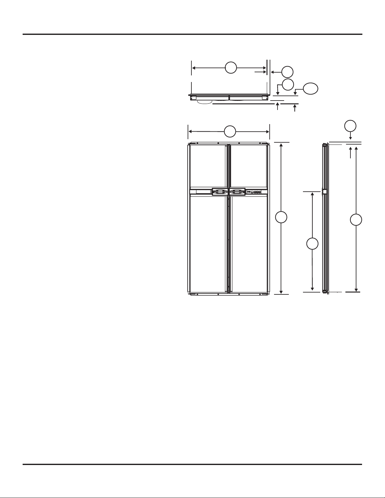
Key Refrigerator Dimensions
Art01734
2
1
8
7
3
5
4
6
123
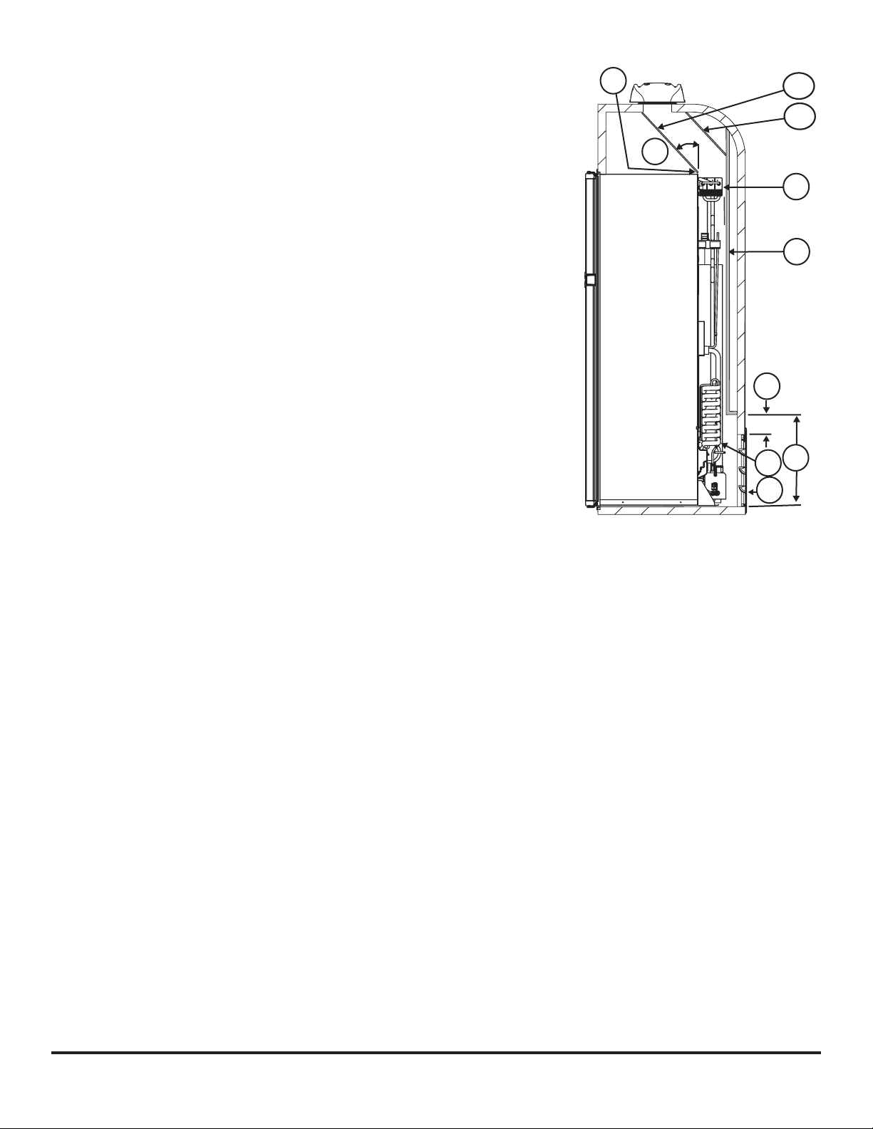
These key refrigerator dimensions are for your reference as necessary (See Art01734).
Refrigerator cabinet width w/o trim - 32.4 in. .......................1
Refrigerator width overall w/ trim - 35.0 in. ..........................2
Refrigerator cabinet to side trim - 1.30 in. ...........................3
Refrigerator cabinet height w/o trim - 63.2 in.......................4
Refrigerator height overall w/ trim - 65.1 in..........................5
Refrigerator cabinet to top/bottom trim - 0.90 in. .................6
Enclosure wall to hinges - 1.92 in. ....................................... 7
Refrigerator cabinet to center of handles - 40.5 in. .............8
Enclosure wall to door (w/dispenser) - 4.47 in.................123
Installation Manual 5
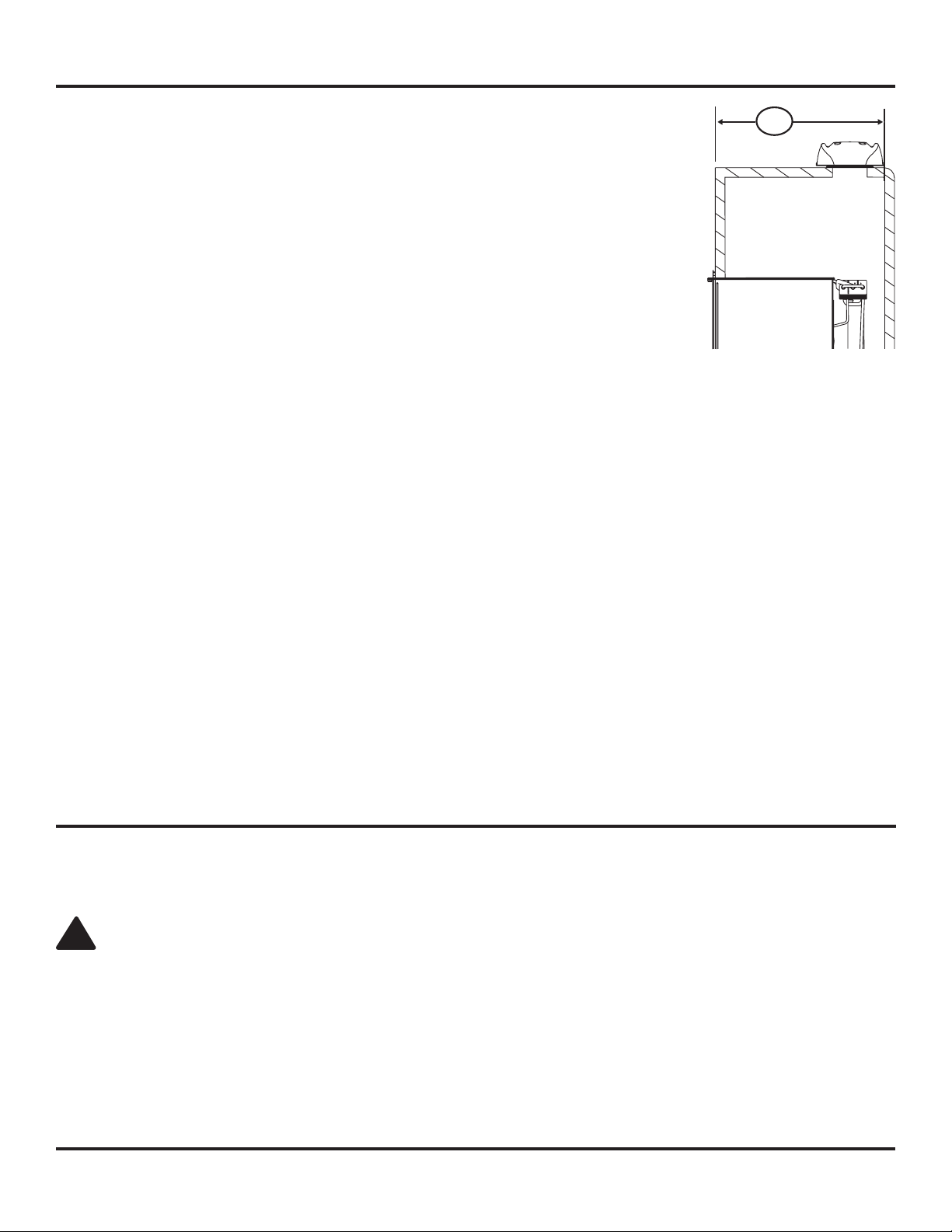
Assemble the Enclosure for the Refrigerator
Art01763
174
!
1. Make sure the enclosure shelf is solid and level. The enclosure shelf must be:
- a metal or a wood panel and extend the full width and depth of the enclosure.
- able to support the weight of the refrigerator and its contents.
- level to maintain door alignment.
2. Make sure there are no adjacent heat sources such as a furnace vent, a hot water heater vent, etc.
3. Make sure the enclosure is 63.25 - 63.38 inches high x 32.69 - 32.82 inches wide x 24 inches deep.
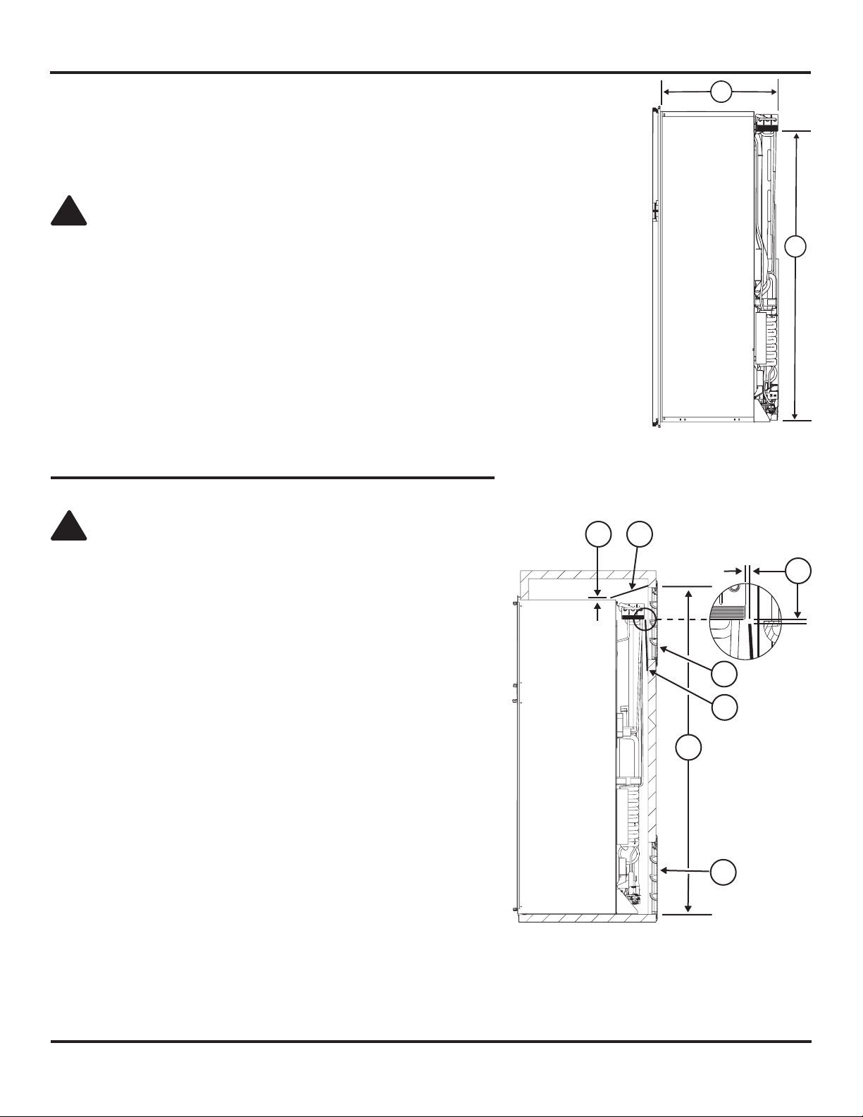
NOTE: Measure the enclosure depth [174] from the interior face of the enclosure to the inside
of the rear wall (See art01763).
4. If there is more than 1/2 inch between either side of the refrigerator and the inside of the enclosure:
- Fill the space with berglass (batt-type) insulation or add a bafe to eliminate the clearance.
- The rear of the batt-type insulation must be between 18 -19 inches from the face of the
enclosure.
- Securely attach the batt-type insulation to the enclosure, so that it remains in this position during refrigerator installation, if it
becomes wet, and in windy conditions.
5. The enclosure face must be perpendicular to the enclosure shelf to provide a combustion seal.
6. The cutout opening must be square and perpendicular to the enclosure shelf to maintain door alignment.
7. Using the following chart, decide which vents and rough opening (RO) sizes to use:
Certied Vent P/N RO Height RO Width
Upper Roof Exhaust Cap 622293 N/A N/A
625240 N/A N/A
Upper Roof Exhaust Vent 616319 24 in. 5 1/4 in.
625161 24 in. 5 1/4 in.
Upper Plastic Exhaust & Lower Intake 621156 13 3/4 in. 21 1/2 in.
Lower Metal Corner Intake 616010 9 3/4 in. 9 3/8 in.
Install the Lower Intake Vent
Install the lower intake vent (See Art01597):
NOTE: The lower intake vent is also the service access opening for the components on the rear of the refrigerator.
WARNING: Make sure the bottom of the opening of the lower intake vent is even with or immediately below the oor level.
This allows any leaking propane gas to escape to the outside and not to collect at oor level.
- Make sure the bottom of the opening of the lower intake vent [9] is even with or immediately below the oor level.
- Make sure that the opening for the lower intake vent is between 1/2 inch and 1 inch from the burner side of the refrigerator
enclosure.
Installation Manual 6
Optional Installation
12
Art01597
12
11
9
130
131
132
N8XX
120X
133
You can change enclosures that were made for Norcold model N8XX refrigerators so that you can put Norcold model 121X refrigerators
into them.
To change the Norcold model N8XX refrigerator enclosure [130] into the Norcold model 121X refrigerator enclosure [131] (See
Art01597):
- Increase the height of the enclosure by 3 3/8 inches [132].
- Increase the width of the enclosure by 8 13/16 inches [133].
- Make sure to add the additional width to the left side of the enclosure (as looking at the rear of the refrigerator).
Install the necessary bafes only as written in the “Install the Upper and Lower Vents” section of this manual.
The locations of the 12 VDC supply, the 120 VAC supply, and the propane gas supply line do not change.
Installation Manual 7
Install an Upper Roof Exhaust Vent
!
!
Art01756
11
12
169
Art01780
13
15
1. Install the upper roof exhaust vent.
CAUTION: Make sure that no sawdust, insulation, or other construction debris is
on the refrigerator or in the enclosure. Debris can cause a combustion hazard and
prevent the refrigerator from operating correctly.
NOTE: Tighten the screws of the upper roof exhaust cap to 10 inch-pounds max. Also make
sure that the air ow around the upper roof exhaust cap is not blocked or decreased
by other roof mounted features such as a luggage carrier, an air conditioner, a solar
panel, etc.
2. Align the upper roof exhaust vent above the lower intake exhaust vent (See Art01597):
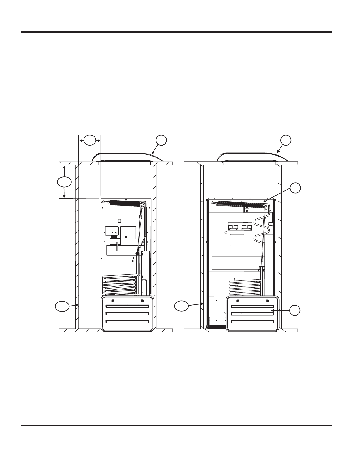
3. Determine the type of enclosure in a vehicle using an upper roof exhaust vent (See
Art01756):
- If the distance from the face of the enclosure to the inboard edge of the roof exhaust
vent opening [169] is more than 17 1/2 inches, install the roof exhaust vent [12] directly
above the condenser [11] of the refrigerator as a vertical enclosure.
- If the distance from the face of the enclosure to the inboard edge of the roof exhaust vent opening [169] is 17 1/2 inches or less,
install the roof exhaust vent [12] inboard from the condenser [11] of the refrigerator as an offset vertical enclosure.
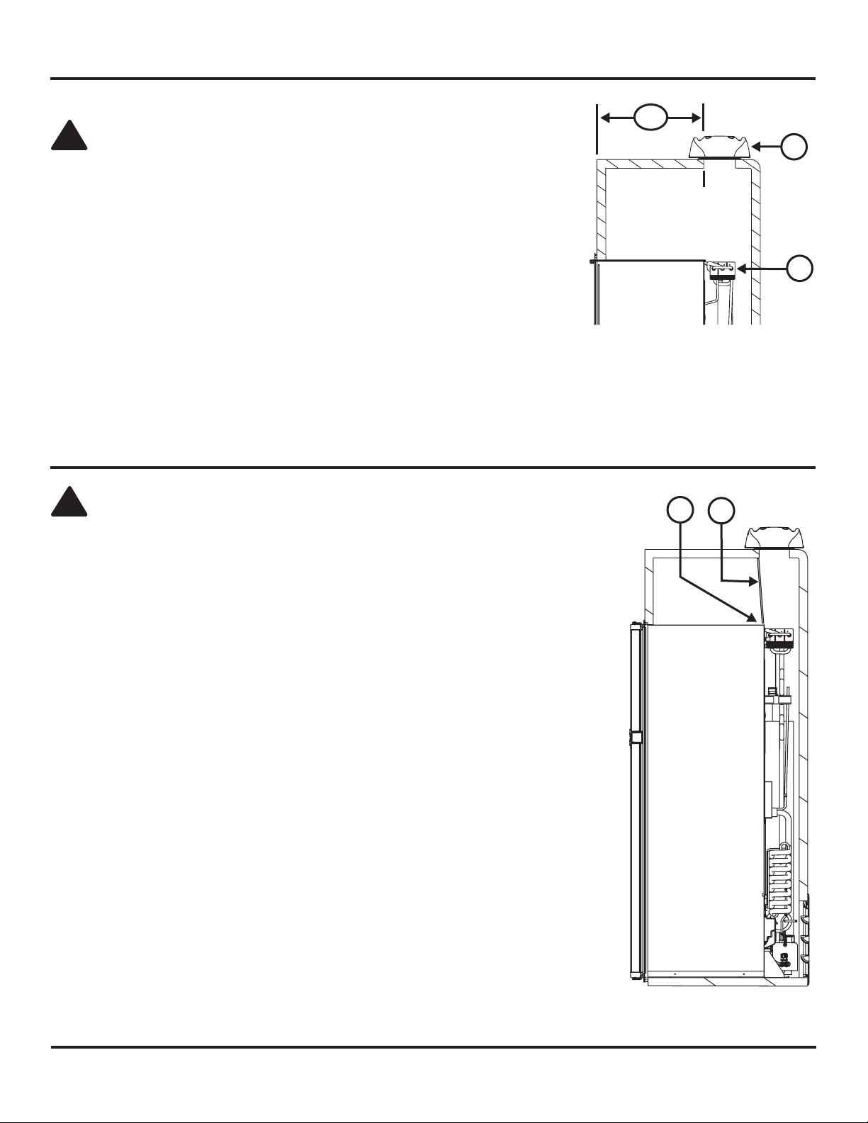
Install the Bafes for an Upper Roof Exhaust Vent
CAUTION: Make sure that all horizontal bafes are the full width of the inside of the
enclosure and are in the correct location. If the bafes are not the full width of the enclosure
or incorrectly located, poor cooling performance can result.
Vertical enclosures:
If the enclosure depth is 24 inches or more and less than 25 inches (See Art01780):
- Install a top bafe [13].
- Make sure there is less than 1/4 inch clearance between the bafe and the top of the
refrigerator.
Installation Manual 8
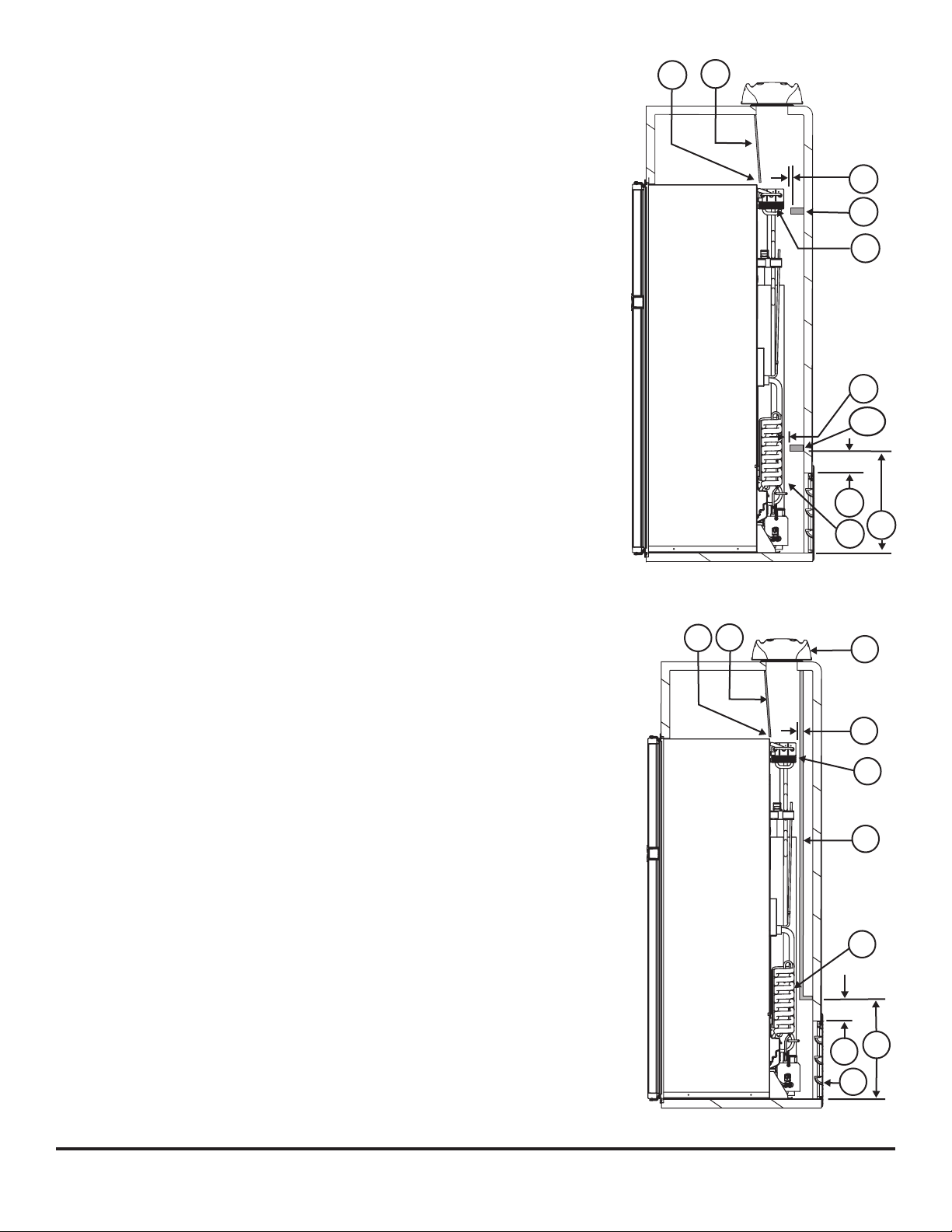
If the enclosure depth is 25 inches or more and less than 26 inches (See Art01781):
Art01781
15
13
19
16
19
171
18
17
10
11
Art01782
12
19
13
15
21
10
18
9
17
11
- Install a top bafe [13].
- Make sure that the top bafe is less than 1/4 inch [15] from the top of the
refrigerator.
- Install a condenser bafe [16] at the lowest edge of the condenser of the refrigerator.
- Make sure that the condenser bafe is 1 inch or less [19] from the condenser.
- Install an absorber bafe [171] 18 inches to 18 1/2 inches above the bottom of the
enclosure [17] (4 1/4 inches to 4 3/4 inches above the top of the lower intake vent
opening) [18] .
- Make sure that the absorber bafe is 1 inch or less [19] from the absorber.
If the enclosure depth is 26 inches or more (See Art01782):
- Install a top bafe [13].
- Make sure that the top bafe is less than 1/4 inch [15] from the top of the
refrigerator.
- Install a wood or an aluminum or galvanized sheet solid box bafe [21] in the rear of
the enclosure.
- Make sure that the bottom of the solid box bafe is 18 inches to 18 1/2 inches
above the bottom of the enclosure [17] (4 1/4 inches to 4 3/4 inches above the
top of the lower intake vent opening) [18] .
- Make sure that the back of the solid box bafe is perpendicular to the bottom of
the enclosure.
- Make sure that the back of the solid box bafe is against the top of the enclosure.
- Make sure that the solid box bafe is one inch or less [19] from the coils [10]
and condenser [11] of the refrigerator.
- Make sure that the solid box bafe is the full width of the inside of the
enclosure.
Installation Manual 9
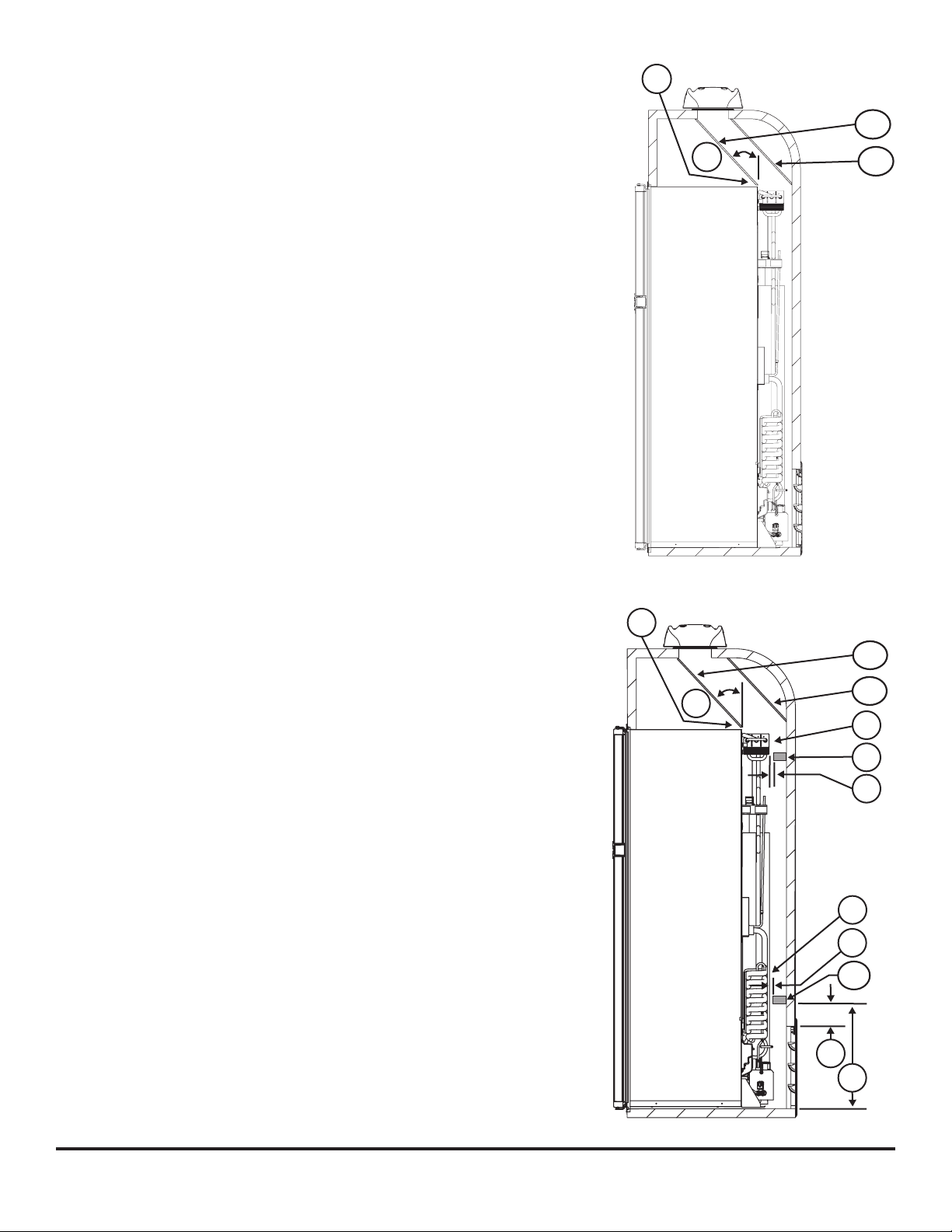
Offset vertical enclosures:
Art01783
15
20
172
173
Art01784
20
15
172
173
10
16
19
18
17
171
19
11
If the enclosure depth is 24 inches or more and less than 25 inches (See Art01783):
- Install an angled top bafe [172] between the top rear edge of the refrigerator and the
inside edge of the upper exhaust vent opening.
- Make sure that the angled top bafe is less than 1/4 inch [15] from the top of the
refrigerator.
- Make sure that the angled top bafe is no more than 45° from vertical [20].
- Install an inside corner bafe [173] between the outside edge of the upper exhaust
vent opening and either the side wall of the vehicle or the solid box bafe (depending
on the vehicle design).
If the enclosure depth is 25 inches or more and less than 26 inches (See Art01784):
- Install an angled top bafe [172] between the top rear edge of the refrigerator and the
inside edge of the upper exhaust vent opening.
- Make sure that the angled top bafe is less than 1/4 inch [15] from the top of the
refrigerator.
- Make sure that the angled top bafe is no more than 45° from vertical [20].
- Install an inside corner bafe [173] between the outside edge of the upper exhaust
vent opening and either the side wall of the vehicle or the solid box bafe (depending
on the vehicle design).
- Install a condenser bafe [16] at the lowest edge of the condenser of the refrigerator.
- Make sure that the condenser bafe is 1 inch or less [19] from the condenser.
- Install an absorber bafe [171] 18 inches to 18 1/2 inches above the bottom of the
enclosure [17] (4 1/4 inches to 4 3/4 inches above the top of the lower intake vent
opening) [18] .
- Make sure that the absorber bafe is 1 inch or less [19] from the absorber.
Installation Manual 10
If the enclosure depth is 26 inches or more (See Art01785):
Art01785
14
20
172
21
18
11
9
17
10
173
9
- Install an angled top bafe [172] between the top rear edge of the refrigerator and the
inside edge of the upper exhaust vent opening.
- Make sure that the angled top bafe is less than 1/4 inch from the top of the
refrigerator.
- Make sure that the angled top bafe is no more than 45° from vertical [20].
- Install an inside corner bafe [173] between the outside edge of the upper exhaust
vent opening and either the side wall of the vehicle or the solid box bafe (depending
on the vehicle design).
- Install a wood or an aluminum or galvanized sheet solid box bafe [21] in the rear of
the enclosure.
- Make sure that the bottom of the solid box bafe is 18 inches to 18 1/2 inches
above the bottom of the enclosure [17] (4 1/4 inches to 4 3/4 inches above the top
of the lower intake vent opening) [18] .
- Make sure that the back of the solid box bafe is perpendicular to the bottom of
the enclosure.
- Make sure that the back of the solid box bafe is either against the top of the
enclosure or against the inside corner bafe [173] (depending on the vehicle
design).
- Make sure that the solid box bafe is one inch or less from the coils [10] and
condenser [11] of the refrigerator.
- Make sure that the solid box bafe is the full width of the inside of the
enclosure.
Installation Manual 11
Install an Upper Side-Wall Exhaust Vent
Art01600
23
22
!
Art01764
13
25
24
9
26
15
15
!
If the design of the vehicle does not allow you to install a roof exhaust vent, install an upper side-wall
exhaust vent.
NOTE: The refrigerator is 23.7 in. min. to 24.0 in. max. from the rear of the breaker to the rear of the
condenser [22] and is 59.0 in. min. to 59.3 in. max. from the bottom of the refrigerator to the
bottom of the refrigerator condenser [23] (See Art01600).
CAUTION: Only use an upper side-wall exhaust vent on refrigerator models that are equipped
with a fan. If you use an upper side-wall exhaust vent on a refrigerator model that is not equipped
with a fan, the refrigerator cooling performance will be poor.
Make sure the refrigerator model is equipped with a fan.
- Install the upper side-wall exhaust vent [24] so that the distance [25] from the bottom of the
enclosure to the top of the rough opening for the upper exhaust vent is at least 63 inches (see
Art01588 and Art01589).
- Align the upper exhaust vent horizontally above the lower intake vent [9].
Install the Bafes for an Upper Side-Wall Exhaust Vent
CAUTION: Make sure that all horizontal bafes are the full width of
the inside of the enclosure and are in the correct location. If the bafes
are not the full width of the enclosure or incorrectly located, poor cooling
performance can result.
If the enclosure depth is 24 inches or more and less than 26 inches (See
Art01764):
- Install a wood, aluminum or galvanized steel top bafe [13] between the
top of the refrigerator and the top of the upper exhaust vent [24].
- Make sure that the top bafe is less than 1/4 inch [15] from the top of
the refrigerator and bafe overlaps the refrigerator 1 inch or less.
- Make sure that the bafe is against the wall of the vehicle at the top of
the upper exhaust vent and less than 1/4 inch above the opening for
the upper exhaust vent.
- Install an aluminum or galvanized steel bent-sheet condenser bafe [26] .
- Make sure that the bend of the condenser bafe is the full width of the
inside of the enclosure.
Installation Manual 12
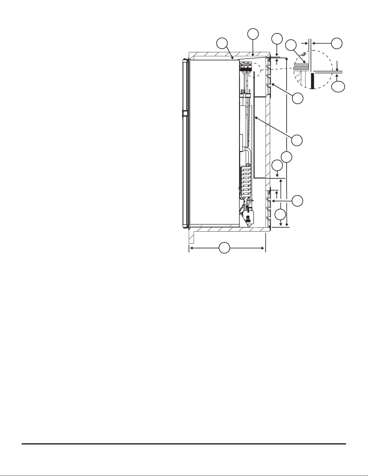
- Make sure that the bend of the condenser bafe is
Art01787
15
13
15
15
24
21
25
18
17
9
27
170
11
ush with the bottom edge of the door frame of the
upper side-wall exhaust vent.
- Make sure that the top edge of the condenser bafe is
1/4 inch or less [15] from the lower rear corner of the
condenser.
If the enclosure depth is 26 inches or more (See Art01787):
- Install a wood, aluminum or galvanized steel top bafe [13]
between the top of the refrigerator and the top of the upper
exhaust vent [24].
- Make sure that the top bafe is less than 1/4 inch [15]
from the top of the refrigerator and bafe overlaps the
refrigerator 1 inch or less.
- Make sure that the bafe is against the wall of the
vehicle at the top of the upper exhaust vent and less
than 1/4 inch above the opening for the upper exhaust
vent.
- Install solid box bafe [21] between the lower intake vent
and the upper exhaust vent.
- Make the solid box bafe either from wood or from an
aluminum or galvanized-steel sheet.
- Make sure that the bottom of the solid box bafe is
18 inches to 18 1/2 inches above the bottom of the
enclosure [17] (4 1/4 inches to 4 3/4 inches above the
top of the lower intake vent opening REF) [18].
- Make sure that the back of the solid box bafe is
perpendicular to the bottom of the enclosure.
- Make sure that the horizontal top of the solid box bafe
is even with the bottom edge of the upper exhaust vent
[24].
- Make sure that the vertical top edge of the solid box baffle is 1/2 inch or less [170] below and 1/4 inch or less behind [15] the
lower rear corner of the condenser [11].
Installation Manual 13
Install an Air Deector (optional)
179
175
24
176
177
178
Art01767
39
38
37
Art01797
37
125
126
Art01794
If the oor plan has the refrigerator on the rear wall of
the vehicle, obey all of the vent installation as written in
the “Install the Lower and Upper Vents” section of this
manual. Install the roof exhaust vent so that:
- The sloped end of the roof exhaust vent is toward
either side of the vehicle.
- The roof exhaust vent is perpendicular to the air
ow over the vehicle.
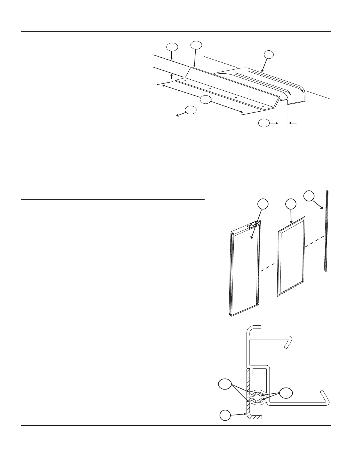
Install an air deector on the roof of the vehicle
between the roof exhaust vent and the front of the
vehicle (See Art01767).
- Make sure that the air deector [175] is between
the roof exhaust vent [24] and the front of the
vehicle [179].
- Make sure that the air deector is at least 3 1/2 inches high [176].
- Make sure that the overall width [177] of the air deector is 32 7/8
- Make sure that the distance between the air deector and the roof exhaust vent is between 2 and 3 inches [178].
Install Decorative Door Panels (non-metal door models)
NOTE: The doors are made to accept decorative panels. The decorative panels must
be 3/16 inch or less in thickness. Install the decorative door panels in the
refrigerator doors before installing the refrigerator in the vehicle.
1. Make two upper door panels that are 16 13/64 inches wide x 18 3/8 inches high:
- Raised panels must be centered on each door and no larger than 15 11/32 inchs
wide x 17 17/32 inches high.
2. Make two lower door panels that are 16 13/64 inches wide x 41 13/64 inches high:
- Raised panels must be centered on each door and no larger than 15 11/32 inchs
wide x 40 11/32 inches high.
3. Install the decorative door panels:
- Pull the panel retainer [37] off of each door [39] (See Art01797).
- Push a decorative door panel [38] into the slots of each door.
- Make sure that each panel retainer is correctly positioned and push the curved
snap [125] of the panel retainer [37] inside of the curved snap [126] of the door
(See Art01794).
Installation Manual 14
 Loading...