

Page 1

Norbain VAIDe
User Manual
Page 2
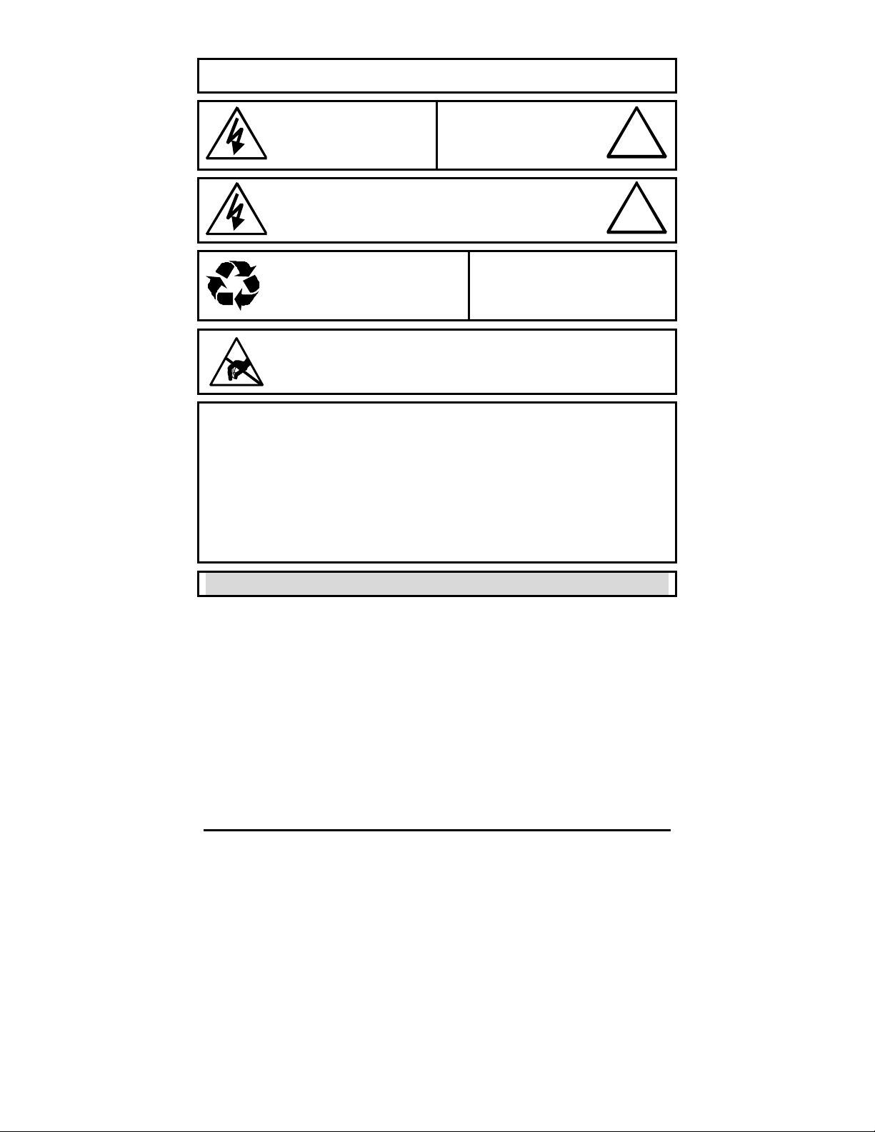
Warning!
To prevent fire and electronic shock, do not expose this product to rain or moisture.
The lightning flash with the arrowhead
symbol, within an equilateral triangle, is
intended to alert the user to the presence of
uninsulated “dangerous voltage” within the
products enclosure that may be of suff icient
magnitude to constitute a risk of electric
shock to persons.
The exclamation point, within an equi lateral
triangle, is intended to alert the user to the
presence of important operating and
maintenance (servicing) instructions in the
literature accompanying the product.
!
Caution!
To prevent electric shock, do not remove cover. No user
serviceable components inside. Refer servicing to qualified
service personnel.
Caution! Lithium Battery
Danger of explosion if battery is incorrectly
replaced. Replace only with the same or
equivalent type recommended by the
manufacturer.
This product contains a recyclable lithium battery.
It may be illegal to dispose of this battery
improperly under local, state, or federal laws.
Check with your local waste management officials
for disposal and recycling options.
Attention
!
Caution! Electrostatic-Sensitive Device!
Use proper CMOS and MOSFET handing precautions, including approved
grounded wrists straps, etc., to avoid damage to this unit or its internal
components, from electric discharge.
Warning!
This equipment generates, uses and can radiate radio frequency energy, and if not
installed and used in accordance with the instructions in this manual, may cause
interference to radio communications. It has been tested and found to comply with the
limits for a Class A computing device pursuant to subpart J of part 15 of FCC rules which
are designed to provide reasonable protection against such interference when operated in
a commercial environment. This equipment has also been tested and found to comply with
the requirements for a CE Class A device and TUV safety standards.
Operation of this equipment in a residential area may cause interference, in which case the
user is required to take all measures that are necessary, at the user's expense, to correct
the interference.
Norbain VAIDe 2 0150-0186b
Page 3

1 Installation .....................................................................4
1.1 Product Description .............................................................................. 4
1.2 Unpacking ............................................................................................ 4
1.3 Installation Environment ....................................................................... 4
1.4 Rear Panel Diagram ............................................................................. 5
1.5 Connections ......................................................................................... 5
1.6 Power-Up ............................................................................................. 6
1.7 Front Panel Indicators .......................................................................... 6
2 Hard Drive Installation ...................................................7
2.1 Opening The VAIDe ............................................................................. 7
2.2 Identifying The Components................................................................. 7
2.3 Mounting The Hard Drives.................................................................... 8
2.4 Configuring Master/Slave ..................................................................... 8
2.5 Connecting Hard Drives ....................................................................... 9
2.6 Powering Hard Drives........................................................................... 9
2.7 Compatible Hard Drives ....................................................................... 9
3 Warranty and Service ...................................................10
3.1 Factory Service................................................................................... 10
3.2 Warranty............................................................................................. 11
0150-0186b 3 Norbain VAIDe
Page 4

1 Installation
1.1 Product Description
The VAIDe is a large, economical, hard drive based storage/archive device. Up
to 8 hard drives can be installed in each VAIDe chassis.
1.2 Unpacking
Check the package and contents for visible damage. If any components are
damaged or missing, do not attempt to use the unit. Contact the supplier
immediately. If the unit must be returned, it must be shipped in the original
packaging.
Package Contents
• The VAIDe unit.
• The Power Cable.
• The User Manual.
• The Archiving Addendum.
• IDE Hard Drive Power Connectors x 2. (If shipped without drives installed)
• IDE Hard Drive Connection Ribbon x 4. (If shipped without drives installed)
• Hard Drive Fastening Screws x 24. (If shipped without drives installed)
1.3 Installation Environment
Power: Ensure that the site’s AC power is stable and within the rated voltage of
the external power supply. Ensure that a reliable Earthing path is maintained.
This unit is intended to be connected to earth ground. If the site’s AC power is
likely to have spikes or dips, use power line conditioning or an Uninterruptable
Power Supply. Do not overload the circuit.
Ventilation: Ensure that the location is well ventilated. Do not obstruct the
cooling vents or fans.
Temperature: Observe the unit’s ambient temperature specifications when
choosing a location for the unit. Extremes of heat or cold beyond the specified
operating temperature limits may cause the unit to fail. Do not install this unit on
top of other hot equipment.
Moisture: Do not expose the unit to rain or moisture. Moisture can damage
internal components. Do not install this unit near sources of water.
Rack Mount: Carefully load the rack so that it remains stable and unlikely to tip
over. The unit is also suitable for desktop installation.
Norbain VAIDe 4 0150-0186b
Page 5
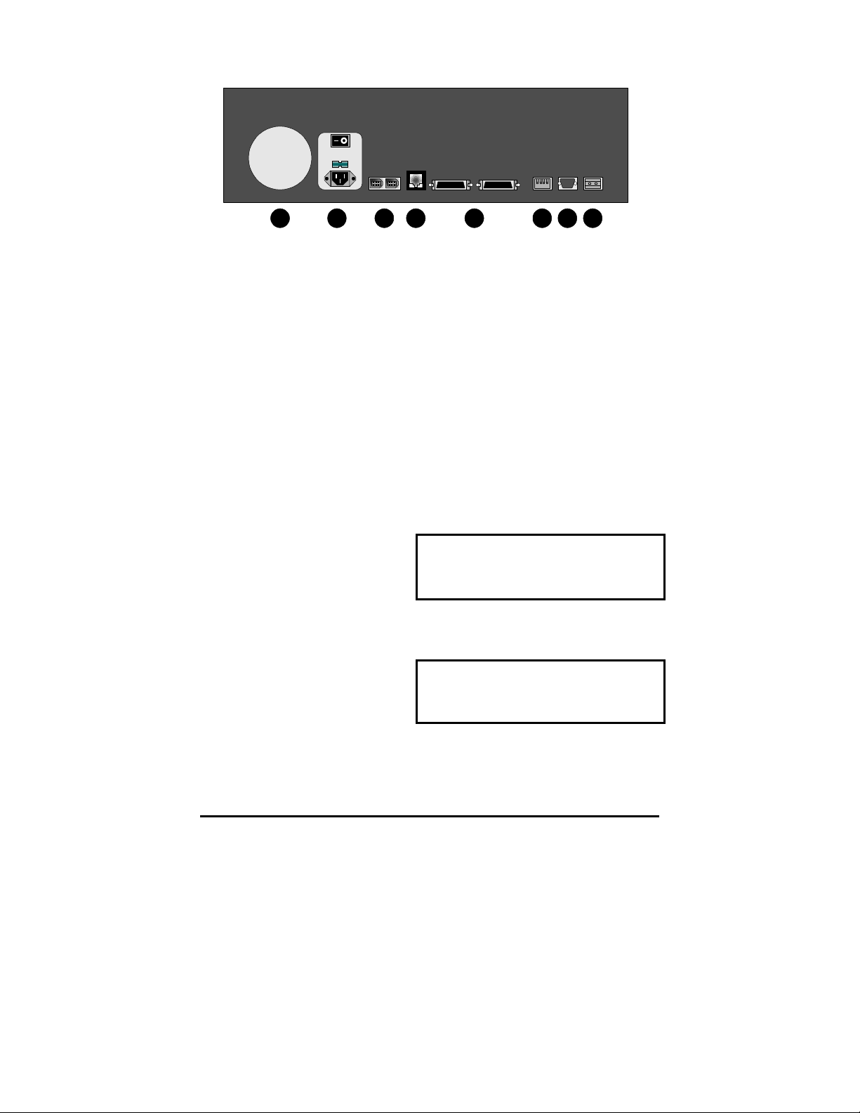
1.4 Rear Panel Diagram
1 2 3 4 5
6 7 8
Rear Panel Elements
1. Cooling Fan: Do not obstruct.
2. Power Connector, Voltage Selector and On/Off Switch.
3. IEEE-1394 Firewire Ports 1 and 2.
4. 10/100 Ethernet Port.
5. SCSI Ports 1 and 2.
6. Dip Switches.
7. RS-232 Port.
8. Alarm Out Relay Connection.
1.5 Connections
The Ethernet, Relay and IEEE-1394 Firewire ports are not functional on this
version of VAIDe.
SCSI Ports 1 and 2
Connect to either SCSI port. Using
the dip switches on the rear of the
unit, set SCSI Termination and
SCSI Power to On.
The unit does not currently support multiple SCSI device connections.
Connector: 50 pin, high density SCSI-2.
Gender (on unit): Female.
SCSI ID: 0.
RS-232 Port
The RS-232 port is used for flash
upgrading the VAIDe operating
system software.
0150-0186b 5 Norbain VAIDe
Connector Type: DB-9.
Gender (on unit): Male.
Cable Required: Null Modem.
Page 6
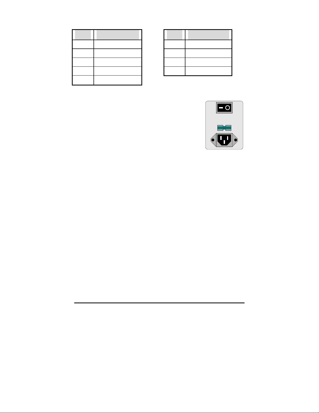
DB-9 Pin Configuration For RS-232 Port
Pin Use Pin Use
1 DCD 6 Not Connected
2 RX 7 RTS
3 TX 8 CTS
4 Not Connected 9 Not Connected
5 Ground
1.6 Power-Up
Select the correct voltage before supplying power to the
unit. Use the voltage selector switch located on the rear
panel of the unit, between the power connector and the
On/Off Switch.
Caution: Applying incorrect voltage could damage unit.
Once the correct voltage has been selected and all
connections have been made, apply power to the unit.
1.7 Front Panel Indicators
Hard Drive Status Indicators (Green Lights)
Light On: Drive present and operating.
Light Flashing: Drive present, error detected.
Light Off: No drive present, or drive damaged beyond recognition.
Hard Drive Activity Indicators (Red Lights)
The light blinks when the drive is being accessed (read or write).
Ethernet Indicators
The Ethernet feature is currently being developed for future implementation.
LCD Display
Once power-up is complete, the LCD displays the total disk storage capacity of
the unit.
Key Pad
This feature is currently under development for future implementation.
Norbain VAIDe 6 0150-0186b
Page 7
2 Hard Drive Installation
This section is required if your unit was shipped without hard drives installed, or if
the user needs to replace a faulty drive.
Caution: Do not allow any metal object to contact the mother board. Do not
allow loose screws to become lost inside the VAIDe chassis. Wear an Electro
Static Discharge protection device any time work is being performed inside the
unit.
2.1 Opening The VAIDe
Before removing the cover, turn off the unit and unplug it. Using a Phillips-head
screwdriver, carefully remove the twelve screws fastening the lid to the chassis.
Save the screws and use them to refasten the lid when finished.
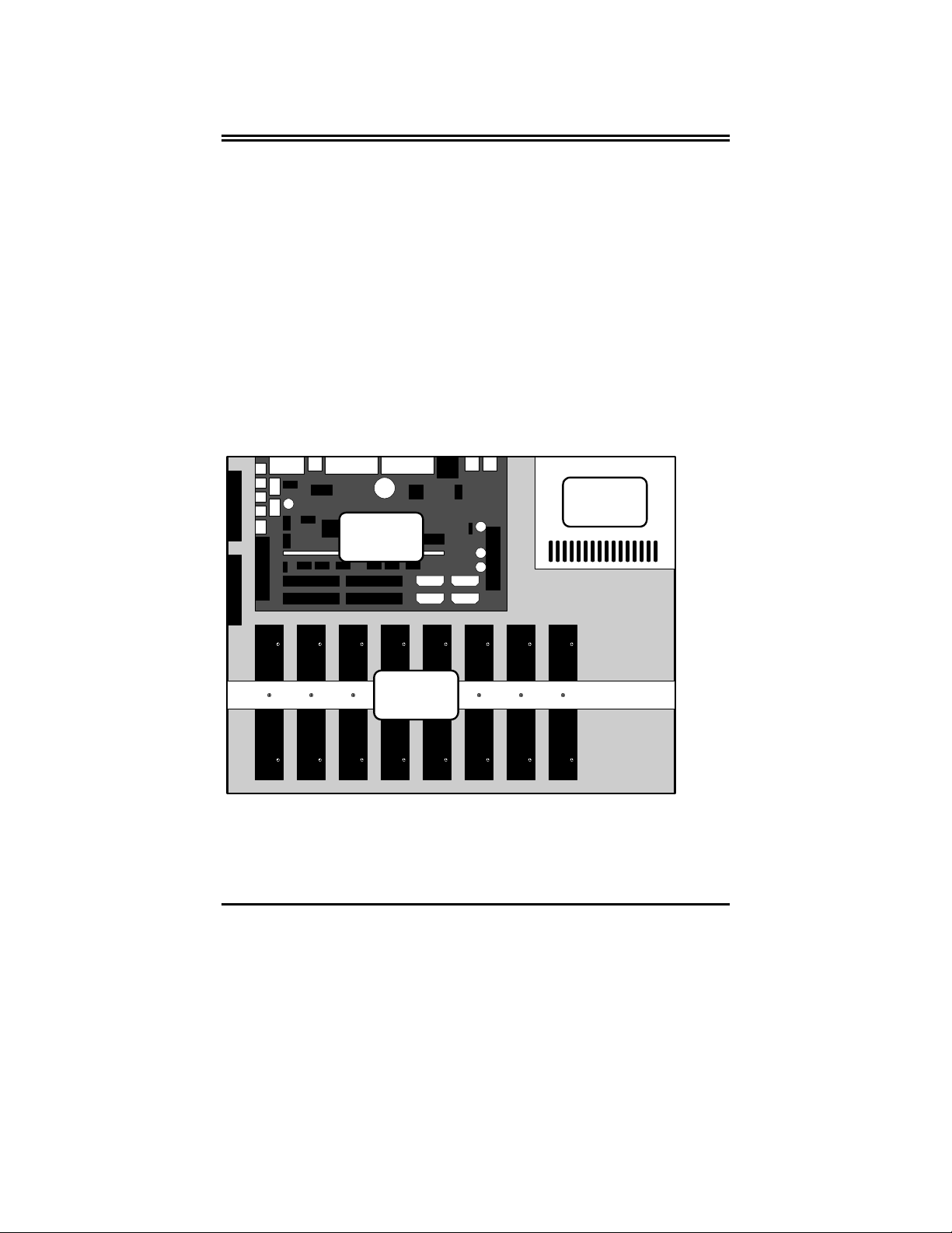
2.2 Identifying The Components
Complete Internal Overview
Power
Supply
Mother
Board
Disk
Array
0150-0186b 7 Norbain VAIDe
Page 8
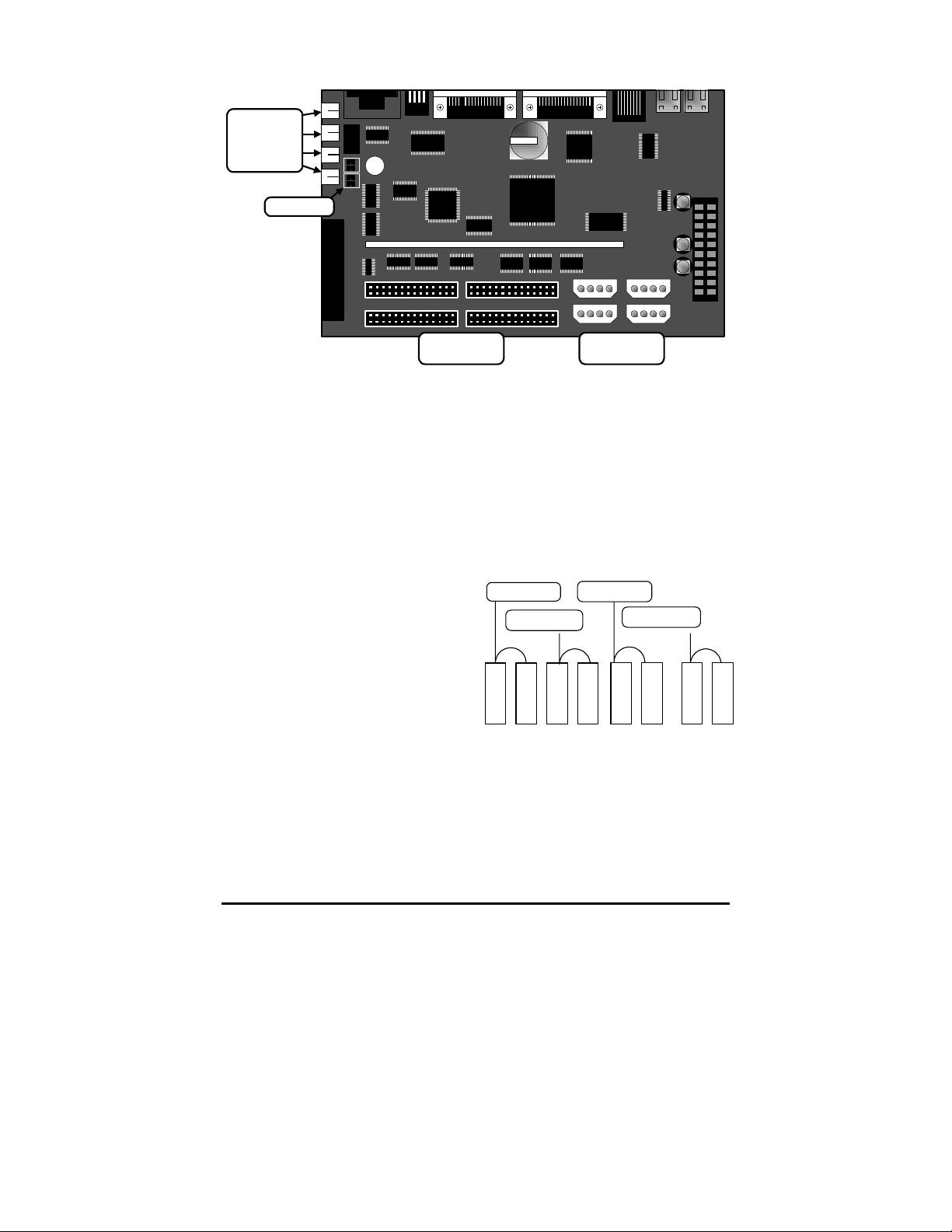
Motherboard Overview
Power
Supply
Load
Resistors
Jumpers
IDE
Connectors
IDE Power
Connectors
2.3 Mounting The Hard Drives
Slide the hard drive into place under the hard drive support bracket. Orient the
hard drive so that the IDE Power Connector is near the bottom of the chassis and
facing the motherboard. Populate the drive array in order, starting from the left.
Fasten the drive in place using the supplied screws. Fasten each drive using two
screws through the bottom of the chassis and one screw in the Hard Drive
Support Bracket.
2.4 Configuring Master/Slave
Hard drives are connected in pairs to
each of the four IDE connectors. Each
pair of hard drives must have a Master
and a Slave. Configure the
Master/Slave setting on each hard
drive individually using the jumpers
provided with the drive. Use the
diagram located on the hard drive to
determine the proper jumper
configuration.
If a single drive is connected to an IDE
connector, it must be configured as a
Master.
When configuring the jumpers on the hard drive, select 16 Heads, Master or
Slave.
IDE Connector #1
IDE Connector
Disk 2
Slave
Disk 1
Master
#2
Master
Disk 3
IDE Connector #3
IDE Connector #4
Master
Disk 5
Disk 4
Slave
Master
Disk 7
Disk 6
Slave
Disk 8
Slave
Norbain VAIDe 8 0150-0186b
Page 9
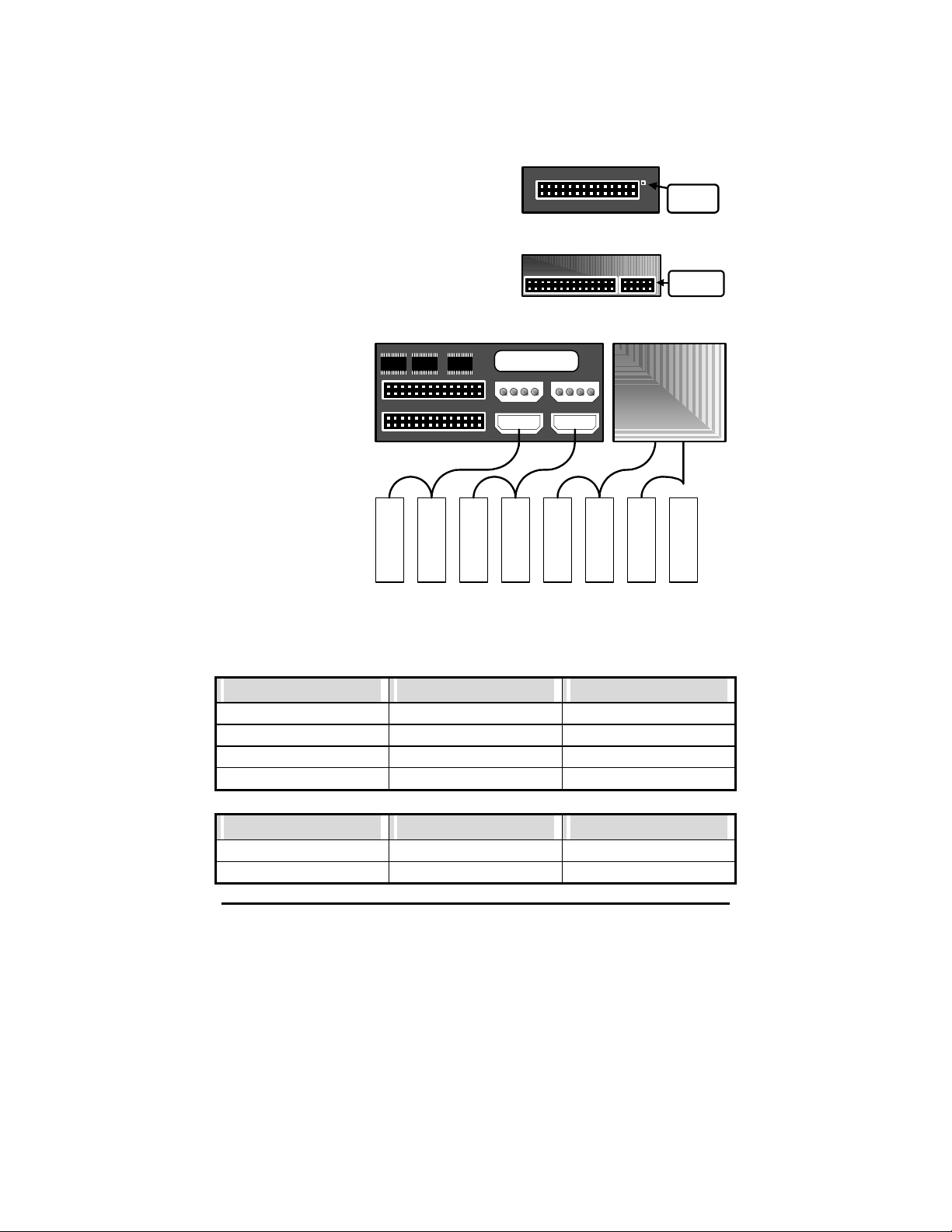
2.5 Connecting Hard Drives
Use an IDE cable to connect drives as shown in the previous diagram. When
attaching the IDE connector, make sure the connectors are oriented properly.
Connecting To The Motherboard
The red stripe on the connection ribbon
should connect nearest the Pin 1 indicator
on the motherboard.
Pin 1
Indicator
Connecting To The Hard Drive
The red stripe on the connection ribbon
should connect near the jumpers on the hard
drive.
Pin 1 Near
Jumpers
2.6 Powering Hard Drives
Connect the hard
drives as shown in
the diagram.
When connecting a
single drive to a
cable, attach the
drive to the
connector at the end
of the power cable
(as shown on the
Drive 7 connection in
the diagram).
Disk 1
Disk 2
Mother Board
Disk 3
Power Supply
Disk 4
Disk 5
Disk 6
Disk 7
Disk 8
2.7 Compatible Hard Drives
The following is a list of hard drives that are compatible with the VAIDe unit.
Maxtor Drives
Model Part Number Size
Vulcan 4W030H2 30GB
Vulcan 4W100H2 100GB
Galaxy 4K040H2 40GB
Galaxy 4K080H4 80GB
IBM Drives
Model Part Number Size
IBM 07N3925 30GB
IBM 07N3935 75GB
0150-0186b 9 Norbain VAIDe
Page 10

3 Warranty and Service
3.1 Factory Service
If the unit requires factory service, contact the dealer who supplied the unit to you
for the correct procedures on returning the unit to the factory or the nearest
factory service center.
If the dealer is not available, contact the manufacturer of the unit as detailed
below and request a Return Material Authorization number (RMA). The units
serial number must be provided before a RMA number can be issued. Units
returned to the factory for service must have freight and insurance prepaid, and
must show the RMA number clearly on all shipping documents. The failure
symptoms must be clearly described by the operator and enclosed with the unit
together with a copy of the original suppliers invoice. Failure to comply with
these instructions will delay service of the unit, and may result in the unit not
being accepted by the Repair Center.
Factory Address
Vista
Norbain SD Ltd.
Norbain House
Eskdale Road
Winnersh Triangle
Wokingham
Berkshire
England
RG41 5TS
Telephone: +44 (0) 118 944 0123
Fax: +44 (0) 118 944 0999
For warranty information, see the following page.
0150-0186b 10 Norbain VAIDe
Page 11

3.2 Warranty
Norbain warrants all of its equipment for five years from the date of purchase.
This warranty specifically covers any defects in materials and workmanship. Any
equipment failures due to improper installation, modification, abuse, or acts of
nature will not be covered by this warranty. The repair department will evaluate
all equipment returned for repair to determine warranty coverage. The Tech
Support Manager will resolve any questions that may arise during evaluation to
make a final determination.
For all warranty repairs: Norbain will cover all costs including parts,
labor, and shipping. Repaired equipment will be returned via the same
method of shipment in which it was received. If a customer requests a
faster return shipment, the difference will be charged.
For all non-warranty repairs: the customer will be billed for parts, labor and
shipping. Labor will be billed in ½ hour increments. If a customer requests a
faster return shipment, the difference will be charged to the customer.
Estimates: Customers requesting an estimate prior to repair will be notified by
phone. If they cannot be reached, they will be notified by fax. If we are unable to
reach the contact person for repair authorization after one phone attempt and two
fax attempts, the equipment will be returned without being repaired. We will hold
equipment no longer than two weeks.
Advance Replacement Policy
When an Advance Replacement is required, we will send the customer
replacement equipment from our stock and receive the returned product in
exchange. The received equipment will be evaluated and the repair department
will determine whether or not it is a warranty replacement. If it is non-warranty,
see our Repair Policy above for details. The following guidelines will be used for
all advanced replacements:
1) Up to 30 days from purchase, Norbain will replace with new equipment.
2) Over 30 days, Norbain will replace with remanufactured equipment.
If you have any questions on this policy, contact Norbain Technical Support at
+44 (0) 118 944 0123
0150-0186b 11 Norbain VAIDe
 Loading...