

Page 1
User Manual
Page 2

NONLINEAR LABS GmbH
Helmholtzstraße 2-9 E
10587 Berlin
Germany
www.nonlinear-labs.de
[email protected]
Document Version: 3.2
Date: December 19, 2018
Author: Matthias Seeber
© NONLINEAR LABS GmbH, 2018, All rights reserved.
Page 3

Contents
I. Safety Instructions, Precautions . . . . . . . . . . . . . . . . . 6
II. Package Contents . . . . . . . . . . . . . . . . . . . . . 8
III. Device Overview . . . . . . . . . . . . . . . . . . . . . 10
1. Introduction . . . . . . . . . . . . . . . . . . . . . . . 12
About the Manual Content . . . . . . . . . . . . . . . . . . 13
2. Setting up the C15 . . . . . . . . . . . . . . . . . . . . . 14
2.1 Mounting the Panel Unit . . . . . . . . . . . . . . . . . 14
2.2 Connections . . . . . . . . . . . . . . . . . . . . . 15
2.3 Start and Shutdown . . . . . . . . . . . . . . . . . . 17
2.4 Setting up a Device for the Graphical User Interface . . . . . . . . 18
2.5 Pedal Integration . . . . . . . . . . . . . . . . . . . 20
3. Basic Concepts . . . . . . . . . . . . . . . . . . . . . . 21
3.1 Performance (Keybed and Hardware Sources) . . . . . . . . . . 22
3.2 Macro Controls . . . . . . . . . . . . . . . . . . . . 23
3.3 Parameters . . . . . . . . . . . . . . . . . . . . . 23
3.4 Modulation Scheme . . . . . . . . . . . . . . . . . . 24
3.5 Presets . . . . . . . . . . . . . . . . . . . . . . 26
3.6 Organization. . . . . . . . . . . . . . . . . . . . . 27
3.7 The Undo Tree . . . . . . . . . . . . . . . . . . . . 27
4. User Interfaces . . . . . . . . . . . . . . . . . . . . . . 30
4.1 Selection . . . . . . . . . . . . . . . . . . . . . . 31
4.2 Editing a Parameter . . . . . . . . . . . . . . . . . . 33
4.3 Editing the Modulation of a Parameter . . . . . . . . . . . . 35
4.4 Macro Controls . . . . . . . . . . . . . . . . . . . . 37
4.5 Hardware Sources . . . . . . . . . . . . . . . . . . . 41
4.6 Presets . . . . . . . . . . . . . . . . . . . . . . 44
4.7 Contextual Info . . . . . . . . . . . . . . . . . . . . 53
4.8 Overviews . . . . . . . . . . . . . . . . . . . . . 57
4.9 The Undo Mechanism. . . . . . . . . . . . . . . . . . 59
4.10 The Rename Mechanism . . . . . . . . . . . . . . . . . 62
4.11 Sound Manipulation . . . . . . . . . . . . . . . . . . 64
4.12 Setup Navigation . . . . . . . . . . . . . . . . . . . 67
4.13 Backups . . . . . . . . . . . . . . . . . . . . . . 68
4.14 Base Unit Functionality . . . . . . . . . . . . . . . . . 69
4.15 Graphical UI Functionality . . . . . . . . . . . . . . . . 70
5. The Synthesis Engine . . . . . . . . . . . . . . . . . . . . 80
5.1 Concept . . . . . . . . . . . . . . . . . . . . . . 80
5.2 Structure . . . . . . . . . . . . . . . . . . . . . . 81
5.3 Components of the Synthesis Engine . . . . . . . . . . . . . 83
5.4 Using Hardware Sources . . . . . . . . . . . . . . . . . 108
6. Setup (C15 System Settings) . . . . . . . . . . . . . . . . . 112
7. Updating the C15 . . . . . . . . . . . . . . . . . . . . 115
8. Specifications . . . . . . . . . . . . . . . . . . . . . 116
9. Parameter Reference . . . . . . . . . . . . . . . . . . . 118
10. Shortcuts for the Graphical User Interface . . . . . . . . . . . . 160
Page 4
Warning Symbols
!
!
!
This symbol indicates a risk of electric shock.
I. Safety Instructions, Precautions
Pedal Integration
Please avoid connecting Pedals when the C15 is running and connect them when the C15
is switched o instead. Only the booting process will recognize a Pedal’s pin assignment
and inner circuit aspects automatically.
Invalid integration of Pedals may lead to overheating or permanent damage of the C15.
This symbol indicates that there are important operating and maintenance
Safety
instructions for this unit in the user manual.
A detailed explanation of Pedal integration and advanced options can be found in
chapter 5.4 Using Hardware Sources.
Safety
Power Supply
Please consider using only the included power adapter. If this is not possible, get a power
6
adapter matching the following specifications:
• 19 V, DC
• 1.5 A or higher
• Plug inner contact: 2.5 mm (+)
• Plug outer contact: 5.5 mm (–)
Do not use power adapters with dierent or unknown specifications, as this may cause
electrical damage on the device! Furthermore, if an external power adapter is used, this
will be at your own risk. Nonlinear Labs will not be liable to damage caused by external
power adapters.
7
Things to avoid
Do not place the C15 on so surfaces (pillows, mattresses, etc.) in order to maintain air
circulation during performance.
As the C15 is an electrical (and electronical) device, strictly avoid water contact.
We strongly advise against opening the C15. The inner parts of the instrument compose
an intricate network, fragile to outside influences and potentially dangerous to the unexperienced seeker. We suggest to leave the device as it is unless you are absolutely certain
about what you are doing.
Try to avoid using the C15 at extreme environmental temperatures. We can not guarantee
a stable performance at very hot or cold conditions. Furthermore, try to also avoid high
humidity or other diicult circumstances.
Always wait for the shutdown process to complete before cutting the power supply. Do
not cut the power supply during performance. Otherwise, data loss can occur.
Page 5
II. Package Contents
QUICK
START
Package Contents
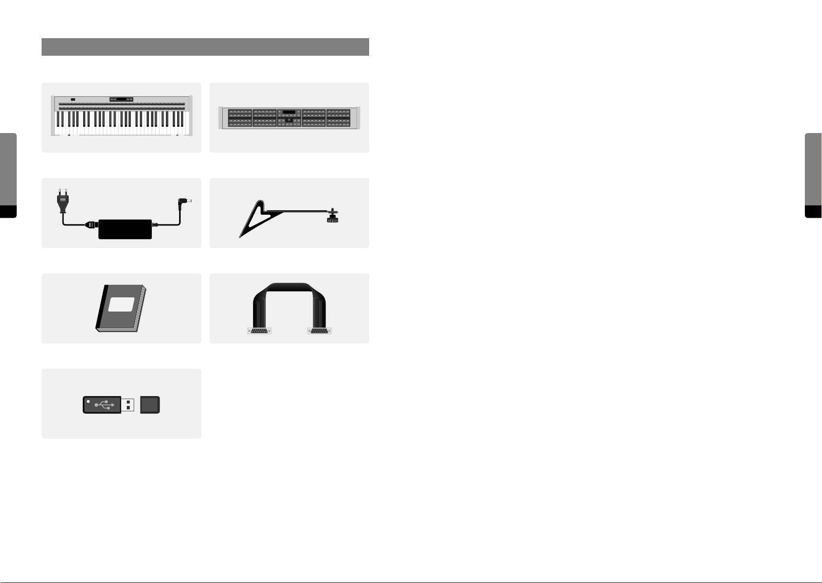
C15 Base Unit
8
Printed C15 Quickstart Manual Unit Connector Cable
C15 Panel Unit
2 Mounting BracketsPower Supply Adapter and Cable
2×
Package Contents
9
USB stick containing:
• the preset library
• the User Manual (PDF and HTML)
The stick has a special format to be used for
installing updates. Therefore keep it safe!
Page 6
Device Overview
⓳
Voices Volume
16 Ribbon 2
17 Headphones Connector
18 Headphones Volume
FLANGER
MACRO CONTROLS UNISON MASTER
ECHO REVERB
CABINET GAP FILTER
Rate Env Time Mod AP Mod Feedbk Mix
Drive Tilt Mix Center Gap Mix
Time Feedback Mix Size Color Mix
19 Output Volume
⓱ ⓲
Device Overview
10
III. Device Overview
➋ ➌ ➍ ➎ ➏ ➐ ➑ ➒ ➓ ⓫ ⓬ ⓭
➊
COMB FILTER
FEEDBACK MIXER
Comb S.V.F. Eects Reverb Drive Level
Preset
Setup
OUTPUT MIXER
STATE VARIABLE FILTER
A – B Pitch Decay AP Tune Hi Cut PM
Store
Sound
A B Comb S.V.F. Drive Level
A – B Comb Mix Cut O Reson Spread FM
Edit
RedoDec (–) Inc (+)
Enter
Fine
Info
Funct Mode
Undo
Default
+
–
Shi
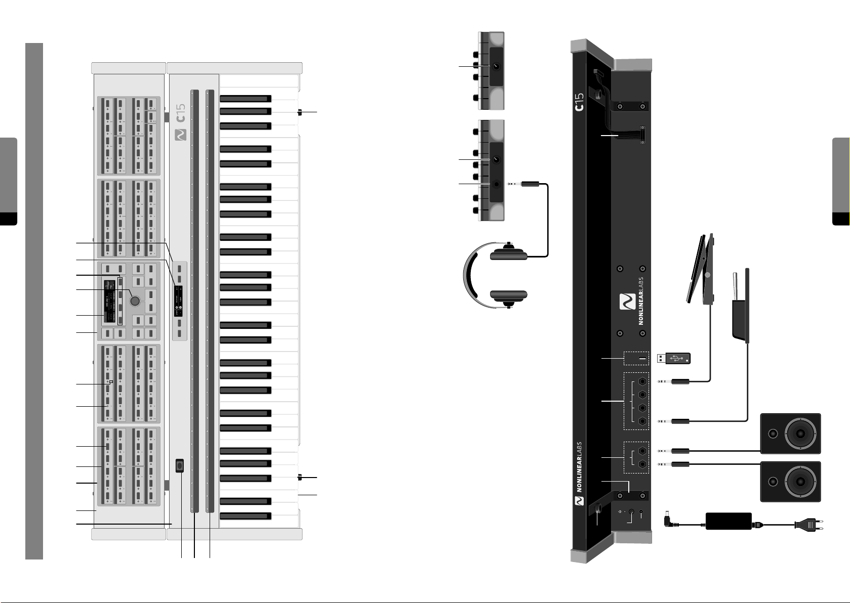
11 So Buttons
12 Base Unit Display
13 Base Unit Control Panel
14 Bender
15 Ribbon 1
11
PEDALSAUDIO OUT USB
12LR 34
SHAPER A
OSCILLATOR A
ENVELOPE A
SHAPER B
OSCILLATOR B
Pitch Fluct Phase PM Self PM B PM FB
Drive Fold Asym Mix FB Mix Ring Mod
ENVELOPE C ENVELOPE A
Attack Deacy 1 Decay 2 Level Vel Level KT Gain
Attack Decay 1 BP Level Deacay 2 Sustain Release
Pitch Fluct Phase PM Self PM A PM FB
Drive Fold Asym Mix FB Mix Ring Mod
ENVELOPE B
ENVELOPE C ENVELOPE B
Attack Deacy 1 BP Level Deacay 2 Sustain Release
Release Level Vel Level KT Level Vel Level KT Gain
⓱ ⓲ ⓳
6 Parameter Selection Indicator
7 Multiple Parameter Indicator
8 Edit Panel
9 Panel Unit Display
10 Encoder
24 USB Connector
25 On/O Button, LED
26 Power Supply Connector
27 Unit Connector Cable
⓴
⓮⓯⓰
1 Base Unit
2 Panel Unit
3 Parameter Panel
4 Parameter Group
5 Parameter Selection Button
20 Panel Unit Fixation Screw
21 Mounting Bracket for Panel Unit
(line level, balanced)
22 Audio Outputs
23 Connectors for Pedals
Page 7

1. Introduction
About the Manual Content
Introduction
12
The C15 is an instrument for the performing musician, designed for playability and
detailed sound editing. Its unique sound character spans from crisp and organic to complex and experimental. The top-quality semi-weighted keybed drives a digital synthesis
engine responding with a wide spectrum of sound colors and intensities.
As a dedicated real-time instrument, the C15 is built for human control. There are no
modulation sources or sequencing modules to create rhythmic patterns — we leave this
to the musician. Instead, the C15 is a decidedly responsive instrument which combines
high-resolution keys, Ribbons, and Pedal inputs.
Every parameter on the C15 can be directly selected by a button. In other words, all
functions are soware-defined but have a dedicated haptic control surface. In addition,
a Graphical User Interface can be displayed and edited on any device that has a browser
and Wi-Fi. Like many classical instrument builders, we have chosen wood for most parts
of the housing. All other parts are made of steel or aluminum. Along with the excellent
keyboard, there is a specially-designed ergonomic (pitch) Bender, two very long touchstrips (Ribbons), and inputs for up to four Pedals.
Marks and Formats used in this Manual
Important notes begin with an exclamation mark and have a grey background:
߱ Ensure that the power supply is not interrupted when using the C15 …
A hint or a background information starts with an “i” symbol:
߰ If you encounter problems navigating the Setup menu intuitively, please refer to …
The following chapters refer to dierent important aspects of working with the C15 instrument. Each chapter tries to exclude the „broader picture“ by focussing only on the crucial
related aspects. Nevertheless, this manual attempts to cover as many details as possible.
When using this manual, it may be helpful to first be certain about your aspect of interest,
before actually looking something up. The following overview may help clarifying:
2. Setting up the C15
At least for the first attempt of putting all components together, consider reading this
chapter describing the whole process.
3. Basic Concepts
This chapter outlines a general approach to the C15 instrument, explaining how to perform, how the modulation mechanism works and how everything is organized.
4. User Interfaces
This chapter explains how to actually work with the instrument. Methods of navigation,
editing and preset access are described in detail for each available interface.
5. The Synthesis Engine
All signal- or DSP- related aspects are subject of this chapter, including details on signal
synthesis and flow, tutorials as well as details on the integration of Hardware Sources.
6. Setup (C15 System Settings)
When already familiar with the instrument, the setup chapter provides insight into the
advanced system settings of the C15.
Introduction
13
A section, explaining a user interaction or task has a heading on dark grey background:
Interaction
Typically, it will be first explained for the Panel Unit. If available (most times), it is followed
by an explanation for the Graphical UI and/or the Base Unit. This type of heading starts
with an arrow and has a lighter background:
→ Graphical UI
→ Base Unit
Page 8
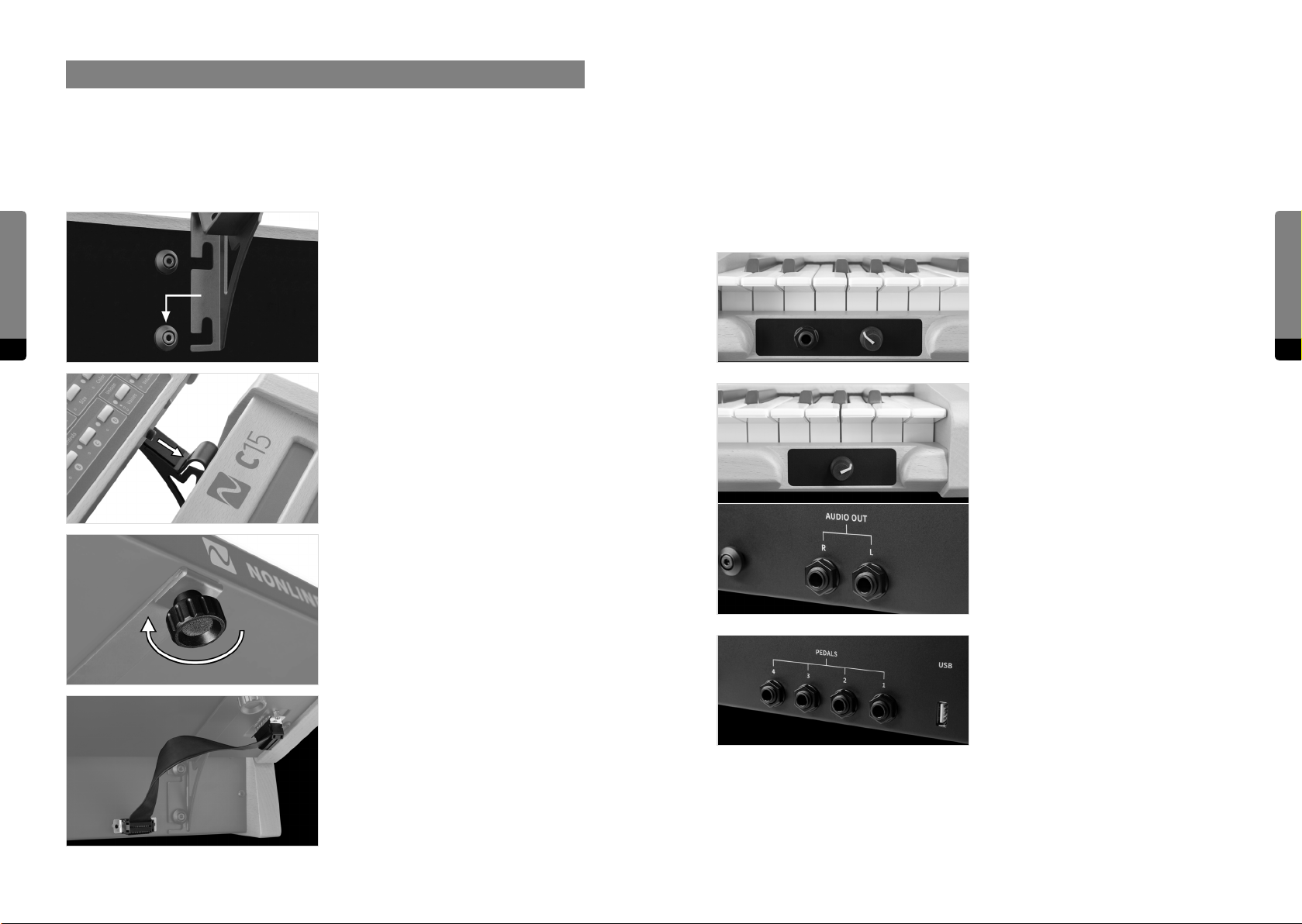
2. Setting up the C15
2.1 Mounting the Panel Unit
Now the C15 is ready to use and can be switched on. In order to disassemble the paired
setup, follow this protocol by applying the described four steps in reverse manner and
order. The C15 Base Unit can be used on its own as well.
Ensure the C15 is switched o before following the next four steps:
Setting up the C15
14 15
Attach mounting brackets to Base Unit by
hanging and snapping.
Place Panel Unit on fixated mounting
brackets. There are two screws (mounting
pins) on the bottom side of the Panel Unit
fitting into corresponding holes near the
peak of each mounting bracket.
Tighten Panel Unit fixation screws in order
to lock Panel Unit in place.
2.2 Connections
Besides the Unit Connector Cable, the following external connections are provided by the
Base Unit:
The headphone output provides a 6.3 mm
stereo headphone socket with separate,
preset-independant adjustable headphone
level.
The audio output provides two 6.3 mm
line-level audio sockets with separate,
preset-independant adjustable output
level. The signals are transformer-balanced
and ground-free, therefore in most cases a
DI-box is not necessary. Unbalanced and
balanced plugs can be connected.
Setting up the C15
Connect Base Unit and Panel Unit with the
Unit Connector Cable.
Four 6.3 mm Pedal sockets are provided for
external Pedal control. In general, any keyboard controller Pedal can be connected.
Nevertheless, only continuous Pedals
allow for a nuanced performance and are
therefore recommended.
Page 9
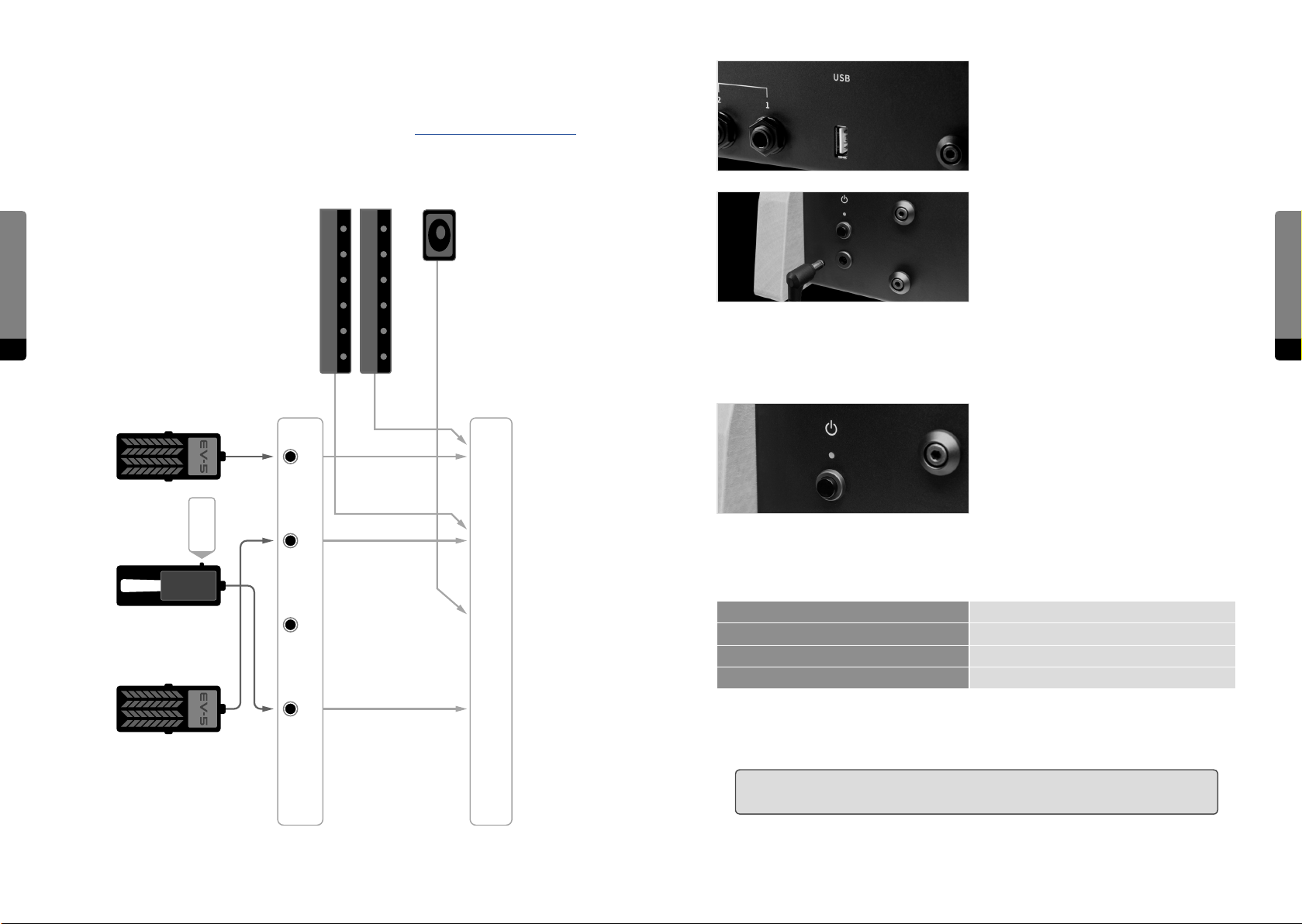
Connecting Pedals and mapping Hardware Sources
Most factory presets use a mapping as shown below. For more information on Hardware
Sources and especially modulation aspects, refer to chapter 5.4 Using Hardware Sources.
The USB connection allows for plugging
in the USB stick, which is part of the C15
package. Via USB, preset banks can be
transferred and updates can be installed.
The C15 comes with its own external power
adapter, which can be connected to the
Setting up the C15
Ribbons
Bender
corresponding appliance inlet. A small LED
next to the inlet indicates the power, boot
and shut-down states of the C15.
16 17
2.3 Start and Shutdown
Turn on the C15 by pressing the power
button and holding it for around a second.
The boot process will take several seconds
before the device is ready to use. The last
settings will be loaded on startup. To shut
down the C15, press the power button and
Continous
Mode !
DP-10
1
2
3
4
Pedals
Controls
Color 1
Color 2
Pitchbend
Sust Pedal
Macro
hold it for around a second. The shutdown process will take several seconds, storing the
current settings for the next startup, before the device will turn o. A small LED next to the
inlet indicates dierent operation states of the C15 as follows:
steady lit on/normal operation
slow blinking booting
fast blinking shutting down
flashing every 2 seconds Standby mode
A flickering LED indicates an irregular operation mode. It means for example the supply
voltage is too low.
߱ Ensure that the power supply is not interrupted when using the C15 (booting,
performance, shutdown) in order to prevent data loss.
Setting up the C15
Page 10

2.4 Setting up a Device for the Graphical User Interface
Concept
The C15 is designed to be of flexible usage and interaction, requiring at least the Base
Unit for connections and performance. In addition, the Panel Unit provides the Hardware
User Interface and therefore access to all parameters, presets and settings.
Setting up the C15
18 19
Finally, the Base Unit also provides a Wi-Fi hotspot in order to connect external devices,
such as smartphones, tablets, laptops and desktop computers. When connected, the
Graphical User Interface can be accessed by using a browser from the external device.
Multiple external devices can be connected simultaneously, each capable of showing
dierent features. However, only one parameter can be focussed at a time, synchronizing
the Hardware User Interface with every connected external device.
Furthermore, the Wi-Fi connection allows for preset interchange and therefore the
possibility of backing up preset banks to the external device. The C15 User Manual is also
accessible in the browser.
߰ If you encounter problems with your setup, there are some things you can do. If possible,
try to restart or change to another browser (or device). If not, or if the problem won’t
disappear, contact us directly. We appreciate feedback and reports of dysfunctionalities
and will try to solve problems quickly.
Wi-Fi Settings
In order to set all relevant aspects of a well defined Wi-Fi connection, enter the setup
menu on the Hardware User Interface (Setup button) and navigate to System Info. Here,
all relevant aspects of the Wi-Fi connection are listed:
Device Name You can give a name to your C15 instrument by focussing on the
device name entry and pressing enter, accessing the Rename
Screen. Once the name is set, an SSID will be generated. The SSID
is composed of a prefix (“NL-C15-”) and the name you just gave to
the instrument.
Setting up the C15
System Requirements
Due to the browser-based implementation of the Graphical User Interface, there are
almost no limitations concerning compatibility between operating systems or browsers.
Basically, the only required device functionalities are the device being capable of a Wi-Fi
connection and an installed browser.
However, in the wide variety of devices, operating systems and browsers, there may be
some restrictions and optimal performance can not be guaranteed. Dierences between
browsers, fast technological advances and frequent updates contribute to a complex
situation, in which it is increasingly hard to state what is suitable.
Nevertheless, there are some experiences that emerged during development and can be
expressed as a recommendation, or understood as minimal requirements:
• The device should run at least with a 1 GHz processing unit and 2 GB RAM space.
• The device display should support multi touch, or a mouse should be connected. A
connected or integrated keyboard is useful in the Graphical User Interface.
• The device display should span at least 7’’ diagonally.
• Although the choice of the browser is completely up to the user, currently (December2018) the best performance is achieved by using a Google Chrome browser.
SSID A Wi-Fi network with the same name as the SSID will be provided
once you scan for available networks on your external device.
When connecting to this network, your external device will be
able to control the C15 over a browser. The SSID is generated
once during the booting process, so renaming your device will
require restarting.
Passphrase The network connection is secured, so a passphrase is needed in
order to establish a connection. When connecting to the network
from your external device, use the displayed passphrase to
confirm. The passphrase can be randomly generated by focussing
on the corresponding entry and pressing enter. The command
“generate new” has to be selected and executed. If you suspect
that the passphrase isn’t secure anymore (because it has been
shared with someone), a new passphrase should be generated.
Address 192.168.8.2
Once the connection is established, post and submit the address
into your browser’s address bar and the Graphical User Interface
should appear in your browser.
߰ If you encounter problems navigating the Setup menu intuitively, please refer to chapters
4. User Interfaces and 6. Setup (C15 System Settings).
Page 11
Browser-specific issues
3. Basic Concepts
As already mentioned, there may be restrictions on some browsers, as there is no real
standard on functionality. We try to keep track of browser-specific issues and oer solutions, if there are any. Please refer to the download section of our website at:
www.nonlinear-labs.de/download/download.html
and get the latest “Browser Issues” PDF.
Setting up the C15
2.5 Pedal Integration
As mentioned, the safe way of integrating Pedals into the system would be when the
20
C15 is switched o. Aer all connections were made, the C15 can be switched on and all
connected Pedals will be recognized and integrated accordingly. For more information
about Pedal integration, refer to chapter 5.4 Using Hardware Sources.
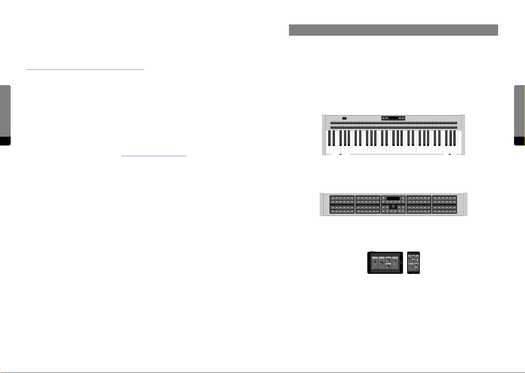
Interaction with the C15 is possible in multiple ways, each consisting of a dierent organisation and optimized layout of represented information, corresponding to the interface
used. However, the basic structure and handling remains comparable, as every interaction possibility follows the main underlying principle.
These general concepts, as well as terms and keywords are subject of this chapter and
will be explained in further detail - in order to understand interaction methods on both
Hardware and Graphical User Interface, as well as the modulation mechanism and
presets. In total, there are three interfaces to consider:
Basic Concepts
21
The Base Unit provides access to all performance-related items (Hardware Sources,
keys). Furthermore, it can be used to edit parameters and navigate presets and banks.
Navigation of parameters is a candidate for future integration.
The Panel Unit can be used to select and edit parameters, modulation and system
settings. Presets, banks and the undo history can be navigated and managed. In short, all
relevant data can be modified on the Panel Unit.
The Graphical User Interface provides complete access to parameters and modulation
and system settings as well. In addition, there are some more helper features and settings
available. The user manual is also available as a separate HTML document.
Each interface holds items that are elements which can be interacted with (most of them
being part of a preset). In the following, items and their features will be explained in
general (before focussing on the individual interfaces in the following chapters).
Page 12
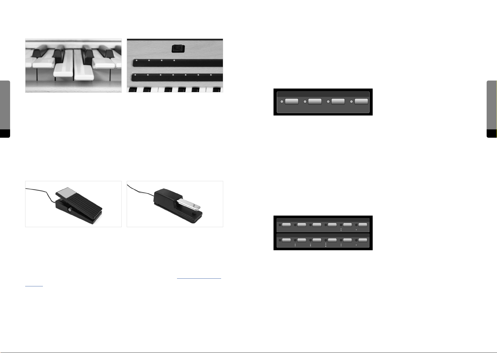
3.1 Performance (Keybed and Hardware Sources)
3.2 Macro Controls
There are four additional parameters, that don’t have any connection or eect by default.
They are called “Macro Controls” and represent the second of three modulation stages.
Macro Controls are potential modulation targets for Hardware Sources, whereas (modulation target) parameters are potential targets for Macro Controls. Therefore, Macro Controls
can be seen as the center stage of the modulation mechanism, redistributing the
movements of Hardware Sources to parameters.
Basic Concepts
A pressed key (le), with Aertouch (right) Bender and Ribbons
Macro Controls
The Keybed as the arguably most important performance input provides polyphonic
control over notes (currently 20 voices) and monophonic Aertouch (as shown in the le
picture above). The semi-weighted, high quality Keybed is produced by Fatar, oering 61
22 23
keys (spanning 5 octaves).
Apart from the integrated, monophonic Aertouch, there are seven additional mono-
The purpose of a Macro Control is to be defined by the sound designer and embodies a
primary tool to bring variation into a sound, as Macro Controls are both interactive (they
can be edited) and performant (they can be modulated).
phonic Hardware Sources supporting performance. (Currently, the whole modulation
mechanism is monophonic.) The Bender, two Ribbons (as shown in the right picture
above) and four external Pedals (as shown in the lower pictures: a continuous and a
switch Pedal) can be integrated and used for expressive play.
3.3 Parameters
Items that are relevant for synthesis are called parameters and are organized in groups.
Each group combines all parameters related to a particular process of the synthesis
engine (such as an envelope). Some parameters are integrated in the modulation
mechanism and can be referred to as “modulation targets”.
Feedback Mixer
Comb
While performing, notes can be played (on the Keybed) and movements can be made (via
the Hardware Sources) in order to bring motion and variability into your sound.
SV Filter Eects Rev Amt Drive Level
A – B
Comb Filter
DecayPitch
PMHi CutAP Tune
The eight Hardware Sources are considered the first of three modulation stages, gathering
the user’s performance input and redistributing movements to the four Macro Controls.
Hardware Sources provide a variety of aspects, depending on the behavior and settings
Currently, there are 239 parameters organized in 21 groups, 89 of the parameters working
as modulation targets.
of an individual source. To explore all related details, refer to chapter 5.4 Using Hardware
Sources.
Basic Concepts
Page 13
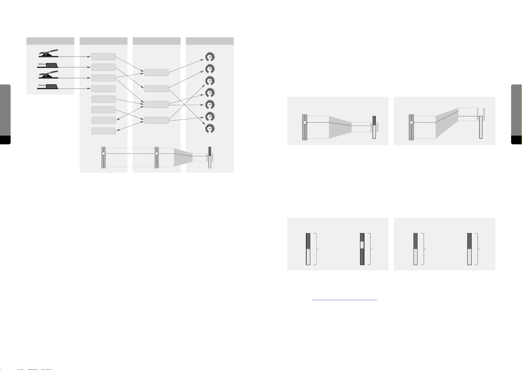
3.4 Modulation Scheme
Modulation amounts define the range for target parameters in which to move according
to the corresponding Macro Control. As neither Macro Control nor the target parameter
External Devices Hardware Sources
Macro Controls Target Parameters
change in position, the amount will always reflect the Macro Control position within the
modulation range (fig. 1)
Pedal 1
Pedal 2
Pedal 3
Basic Concepts
Pedal 4
Bender
Aertouch
MC A
MC B
MC C
There can be cases where the modulation range exceeds the parameter range, also called
virtual overdrive. When a modulation moves a parameter out of its operational range, it
will remain at the corresponding edge (clipped) until the modulation went back far
enough to fit the parameter range again (fig. 2).
Macro Control Mod Amount ParameterMacro Control Mod Amount Parameter
Ribbon 1
Ribbon 2
24 25
Hardware Source
MC D
Macro Control Mod Amount Parameter
fig. 1 fig. 2
When comparing unipolar and bipolar target parameters (fig. 3), it becomes obvious that
the full modulation range (-100% ... 100%) for bipolar parameters is eectively twice the
The modulation mechanism translates movements of the user performance (on the
Hardware Sources) into parameter movements, increasing the variation and expressivity
of a preset.
There is no automatic modulation (like an LFO - except for the Flanger) within the C15
instrument, only the user has an influence on movements.
In the sound engine, almost all parameters operate as smoothers. The smoothing time
depends on the instrument settings and operational context. (There is a smoothing time
for parameter edits, a transition time for preset recall and a smoothing time for modulation as well, defined for each Macro Control, which is currently in development).
In a preset, the flow of movements is defined by several amount parameters, weighting
the amount and direction of movements. Each Hardware Source features a separate
unipolar parameter modulation range (0% ... 100%).
When a target parameter has a linear scaling, the modulation amount can be displayed in
the same format, sharing the parameter’s unit. Nonlinear scalings of target parameters
require the modulation amount to be in percent (fig. 4).
unipolar bipolar
100 %
50 %
0 %
100 % 200 %
100 %
–100 %
50 %
0 %
linear exponential
130 ST
55 ST
-20 ST
150 ST 100 %
16000 ms
40 ms
0 ms
amount for each Macro Control. Multiple Hardware Sources can aect one specific Macro
Control. Any target parameter features an MC selector and modulation amount, completing the routing of modulations. A target parameter can only follow one Macro Control.
The eect of Hardware Sources on Macro Controls is essentially dependant on the type
and settings of the source, so it is hard to generalize.
The eect of Macro Controls on target parameters on the other hand can be generalized.
More information about Hardware Sources and the modulation mechanism can be found
in chapter 5.4 Using Hardware Sources. The section „Modulation Aspects“ explains the
current standard setting, which is commonly used in the factory presets.
fig. 4fig. 3
Defining modulation aspects of a parameter happens in relative context to both the Macro
Control and the parameter as neither of them changes when editing modulation amounts.
Basic Concepts
Page 14
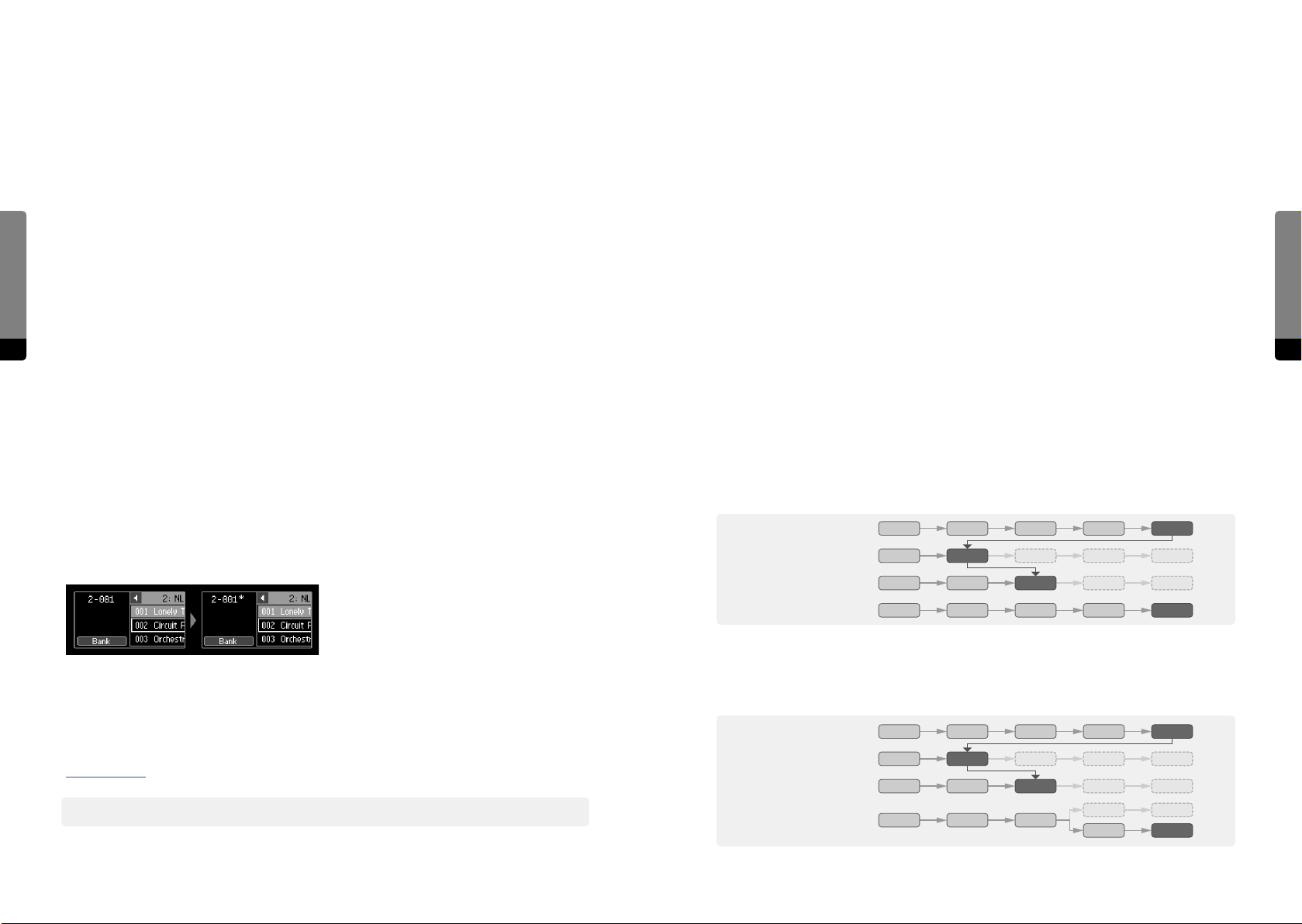
3.5 Presets
3.6 Organization
At any time, the current sound can be stored (and later recalled) as a preset. Presets are
organized in banks, so that every preset has a unique path (bank number/preset number).
There are some more aspects of a preset, which are explained in the following:
All accessible items on the C15 instrument are organized into functional groups. Param-
eters are grouped according to their functional relations in the Sound Engine, Hardware
Sources and Macro Controls are grouped close to each other, and other items are
organized in menu structures.
Preset Name
Each preset can have its own user-definable name. When storing a preset, a name will be
Basic Concepts
requested. However, the name of a preset can be changed later on.
Preset Number
The preset will have a certain position in the containing bank. Together with the bank
number, a unique number emerges for each preset and will be shown on each user interface. For example, the unique number “1-001” refers to the first preset in the first bank.
26 27
The Hardware User Interface (consisting of Base and Panel Unit) provides quick access to
all parameters, which are packed in groups. However, not every parameter is accessible
by one click, as several parameters can be stacked behind one selection button.
In the Graphical User Interface, every parameter and every bank will be shown in the main
area. This requires physical space to represent all necessary information, which may not
be suiciently provided by the screen dimensions and resolutions of external devices. In
order to cope with these limitations, zooming is a crucial part of working with the Graphi-
cal User Interface, as dierent levels of detail emerge on dierent zoom levels.
Preset Info
Every preset holds a small collection of metadata, most of them being automatically
defined when storing. Besides the device name, the soware version and a time stamp,
there are elements to be defined by the user: The name of a preset can be edited, the
position in the bank can be set, a color tag can be associated and a comment text is
provided. In the comment text, sound descriptions or playing instructions can be placed.
In addition, the preset comment text will be evaluated when searching for presets with
certain keywords. This works especially well when keywords are defined as tags with the
hashtag symbol “#”.
Change Recognition
3.7 The Undo Tree
The usual undo history of a program would be a list-like data structure. When an editing
action is tracked, it will be simply appended. If a certain number of edits was undone,
they will be lost when continuing with new editing actions.
undo three steps:
redo one step:
edit 1five editing steps:
edit 1 edit 2 edit 3 edit 4 edit 5
edit 1 edit 2 edit 3 edit 4 edit 5
edit 2 edit 3 edit 4 edit 5
Basic Concepts
When changing a loaded preset, the system will recognize any change and indicate it
by a star symbol (“*”) behind the unique number. When storing a sound aer changes
occurred, it will be interpreted as a new preset by the system, unless the user forces
overwriting an existing preset.
More information about dealing with changes to loaded presets can be found in chapter
4.8 Overviews.
߰ Note that modulations, which will change parameters, are considered as a preset change.
two new editing steps:
edit 1 edit 2 edit 3 edit 6 edit 7
However, the C15 undo history is realized as a tree-like data structure. All editing actions
will be tracked and new branches will emerge when continuing with new editing actions
(aer having undone a certain number of edits).
undo three steps:
redo one step:
two new editing steps:
edit 1five editing steps:
edit 1 edit 2 edit 3 edit 4 edit 5
edit 1 edit 2 edit 3 edit 4 edit 5
edit 1 edit 2 edit 3
edit 2 edit 3 edit 4 edit 5
edit 4 edit 5
edit 6 edit 7
Page 15

Using this mechanism, there will be no loss of editing steps, as all steps and branches are
accessible. Nevertheless, an ever-growing undo tree will require lots of memory and may
be capable of slowing down the system. This can be avoided by making a certain element
the new root of the tree (elements prior to that position will be lost in this case) or by
deleting inactive branches of the undo tree.
Within a branch, the mechanism is quite similar to the ordinary list-based undo, providing
backward and forward navigation via undo or redo. The extended tree-based functional-
Basic Concepts
ities emerge when navigating to other branches.
The C15 undo mechanism tracks dierent user actions. Parameter selection, edits to
parameters, preset recalls and edits to presets and banks can be undone. However, the
modulation mechanism is not integrated into the undo mechanism, as it is part of the
user performance.
28 29
Basic Concepts
Page 16
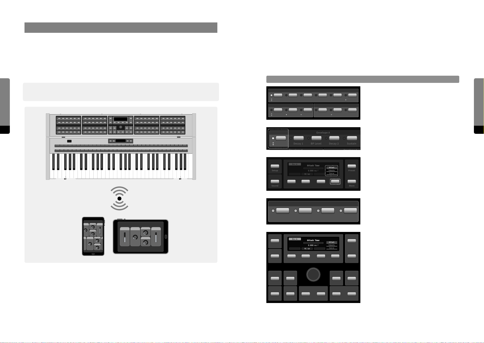
Release
4. User Interfaces
4.1 Selection
As described, the C15 provides two dierent user interfaces. The Hardware User Interface
consists of both Base Unit and Panel Unit, providing haptic („hands on“) control.
The Graphical User Interface is available on external devices via Wi-Fi connection and provides a detailed parameter and preset representation. Multiple devices can be connected
The C15 architecture was designed to oer quick access to all items and aspects, pro-
viding one central area representing the current focus. This main principle (of focussing
on one item at a time for further editing) aects each interaction on any available user
interface. As mentioned, the current focus will be shared with all involved devices.
in parallel, each focussing on dierent aspects.
Selection
User Interfaces
30 31
߰ Note that all available interfaces operate in a synchronized manner, sharing the same
state and focus.
Envelope A
Attack
Decay 1 BP Level Decay 2 Sustain Release
Envelope C
Attack
Envelope A
Envelope A
Parameter Panels provide Parameter
Selection Buttons. A lit LED indicates the
current focus.
GainLevel KTLevel VelDecay 2Decay 1
Multiple parameters can be provided by
one Parameter Selection Button (indi-
Attack
Decay 1 BP Level Decay 2 Sustain
cated by circles below the LED).
The Parameter Selection Button or So
Setup
Sound
Macro Controls
Button 4 will cycle through the stack.
Preset
Store
Macro Controls appear as a distinct group.
Pressing a Selection Button twice will
redirect to the Hardware Sources.
User Interfaces
The following chapters explain how to focus on items and their aspects for further editing.
Setup
Sound
Info
Shi
Fine
Default
Enter
Undo
The Panel Unit Display will provide a
corresponding screen for the selected item.
Preset
Buttons of the Edit Panel provide access to
all item aspects.
Store
Edit
RedoDec (–) Inc (+)
Page 17
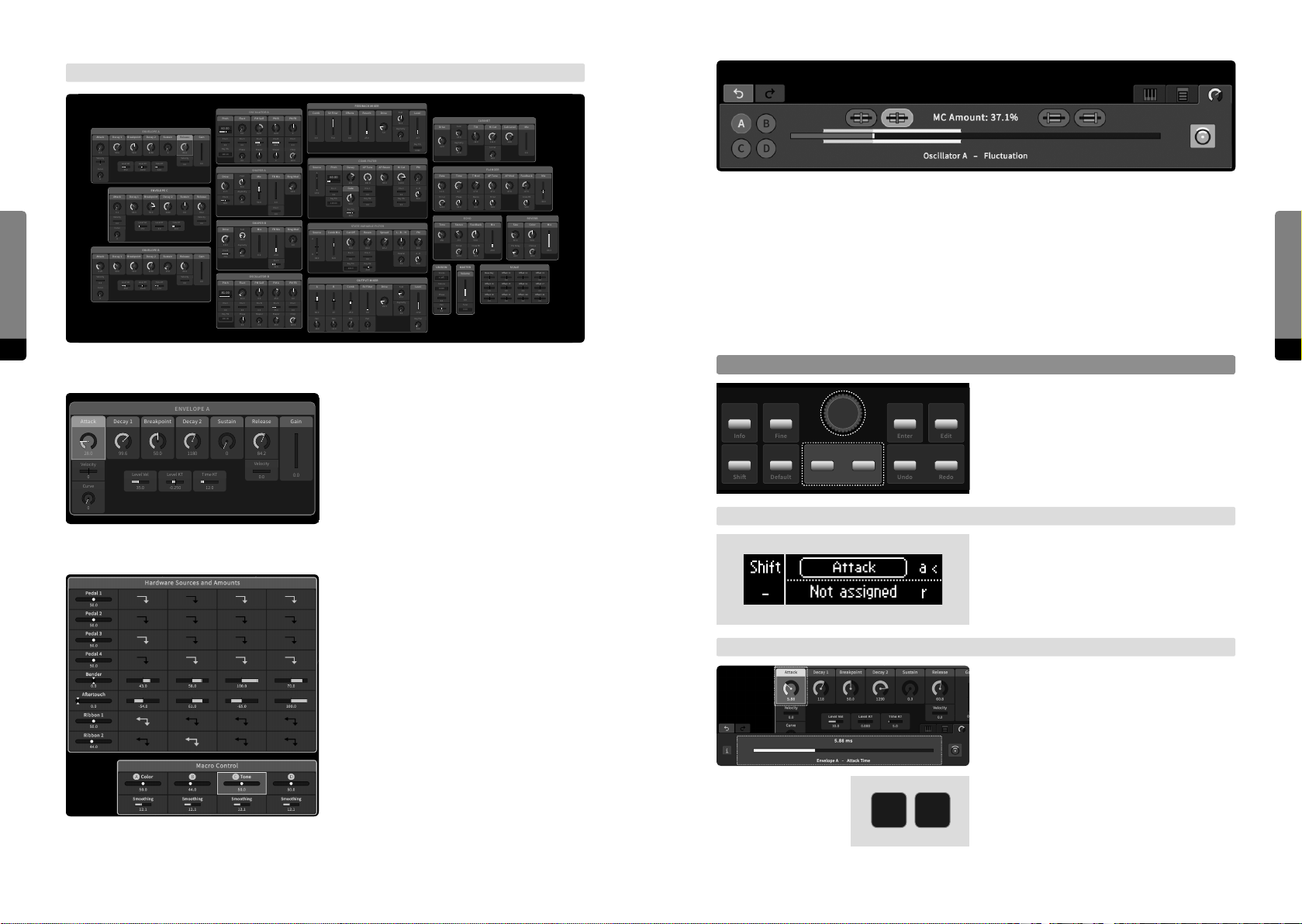
→ Graphical UI
0.0
ENVELOPE A
Velocity
0.0
Release
0
Curve
Decay 2
1180
Breakpoint
50.0
Attack
28.0
Decay 1
99.6
Velocity
0
0
Sustain Gain
84.2
Time KT
12.0
Level KT
-0.250
Level Vel
35.0
OSCILLATOR A
PM FB
PM Self
Fluct
Pitch
ENVELOPE A
Decay 2
Breakpoint
Attack
Decay 1
0.1
99.6
Velocity
0
Curve
0
Attack
0.1
Velocity
0.0
User Interfaces
32 33
All parameters are shown in the main area and can be selected by clicking.
Curve
0
Attack
Decay 1
2.25
99.6
Velocity
0.0
Curve
0
Sustain Gain
1180
50.0
0
Time KT
Level KT
Level Vel
12.0
-0.250
35.0
ENVELOPE C
Decay 2
Breakpoint
Decay 1
1040
50.0
66.3
Time KT
Level KT
Level Vel
0.0
15.0
ENVELOPE B
Decay 2
Breakpoint
Sustain
1180
50.0
15.0
Time KT
Level KT
Level Vel
17.0
-0.100
35.0
60.00
Release
Env C
0.0
Key Trk
84.2
100.10
Velocity
0.0
0.0
Drive
11.5
Release
Sustain
Env A
40.0
84.2
0.0
Velocity
0.0
20.0
Drive
18.0
Env B
75.0
Release
Gain
84.2
Velocity
0.0
Pitch
0.0
81.00
Env C
0.0
Key Trk
100.06
PM B
0
62.0
0.0
-22.0
Env C
Env A
Env B
Shaper
SHAPER A
SHAPER B
OSCILLATOR B
PM Self
Env B
Shaper
47.0
0.0
Mix FB Mix
50.0
Mix FB Mix
0.0 23.0
0.0
0.0
0.0
Env C
80.0
0.0
Shaper
Chirp
0
120.0
Ring Mod
14.0
0.0
Env C
0.0
Ring Mod
0.0
Env C
22.0
PM FB
PM A
0.0
25.0
Env A
Env C
33.0
0.0
Shaper
Chirp
33.0
120.0
0.0
Phase
0.0
Fold
50.0
Asymetry
0.0
Fold
100.0
Asymetry
18.0
Fluct
16.0
Env C
0.0
Phase
0.0
FEEDBACK MIXER
COMB FILTER
AP Tune
140.0
Env C
0.0
Key Trk
0.0
Reson
66.0
Env C
0.0
Key Trk
-14.0
OUTPUT MIXER
SV Filter
Pan
Fold
Drive
Level
50.0
Asymetry
5.0
0
Key Trk
0.000
PM
Hi Cut
AP Reson
0.0
118.0
33.0
Env C
A - B
0.0
Key Trk
50.0
0.0
FM
L - B - H
Spread
18.0
0.0
18.2
A - B
Parallel
50.0
0.0
Fold
Drive
Level
25.2
Asymetry
22.3
0.0
0
Key Pan
14.0
Fold
Tilt MixHi Cut
25.0
Asymetry
22.0
25.0
T ModRate Time
11.6 47.2
Phase
Hi Cut
Stereo
90.0
120.0
0.0
ECHO
Time Stereo
50.0256 -9.5 50.030.0
Hi Cut
Cross FB
120.0
50.0
MASTER
UNISON
Voices
Volume
1 (o)
Detune
0.000
Phase
0.0
0.0
Tune
Pan
0.00
0.0
CABINET
Cab LevelDrive
-14.0
112.0-12.0
Lo Cut
30.0
FLANGER
AP Mod
47.8
Hi Cut
50.0
MixFeedback
Size Color
Pre Delay
20.0 86.3
26.3
SCALE
Base KeyCOset +1
0.0
Oset +4
Oset +5
0.0
0.0
Oset +8
Oset +9
0.0
0.0
Feedback
Cross FB
Oset +2 Oset +3
Oset +6
0.0
Oset +10
0.0
SV FilterComb ReverbEects
0.0 0.0 25.0 -8.775.0
Decay
Pitch
Source
A
60.00
251
Env C
Gate
B
13.0
0.0
Key Trk
100.00
50.0
Key Trk
66.0
STATE VARIABLE FILTER
Cut O
Comb Mix
Source
A
75.0
Env C
B
32.0
84.0
0.0
Key Trk
100.0
A
B
Comb
66.0 -29.0 0.025 -4.32
Pan
Pan
Pan
-12.0
-18.0
12.0
A highlighted element background indicates the current selection. The mouse
wheel or pinch gestures on the main area
background will zoom into the provided
map. On dierent zoom levels, dierent
0.0
MixAP Tune
-67.02.7 27.8
-30.0
50.0
REVERB
Mix
Chorus
68.3
0.0
Oset +7
0.0
Oset +11
0.0
The expandable tab area shows and provides all item-related aspects. Parameter edits
can be realized in the Parameter tab.
The chapters 4.2 to 4.6 refer to a selected parameter- or preset-related item. Further
(menu-related) items and access to them will be explained in the chapters 4.7 to 4.15)
4.2 Editing a Parameter
Adjust Control Position, coarse
Use the Encoder to adjust the currently
selected parameter.
Info
Shi
Fine
Default
Enter
Undo
The Dec and Inc buttons can be used for
Edit
stepwise adjustments.
RedoDec (–) Inc (+)
details emerge. High priority parameters
are always visible.
→ Base Unit
The Mode button can put Ribbon 1 into
Edit mode. Display and touch strip of Rib-
Macro Controls and Hardware Sources
appear as separate groups in the main
area, providing all related aspects.
bon 1 will represent the currently selected
parameter, while Ribbon 2 still operates in
Play mode.
User Interfaces
→ Graphical UI
If the external device features a mouse or
touch display, use drag gestures to adjust
the currently selected parameter. (Use the
Parameter tab slider or main area element,
if GUI settings allow for it.)
If the external device features a keyboard,
MK
K and M keys can be used for stepwise
adjustments (K for incremental, M for
decremental adjustments).
Page 18
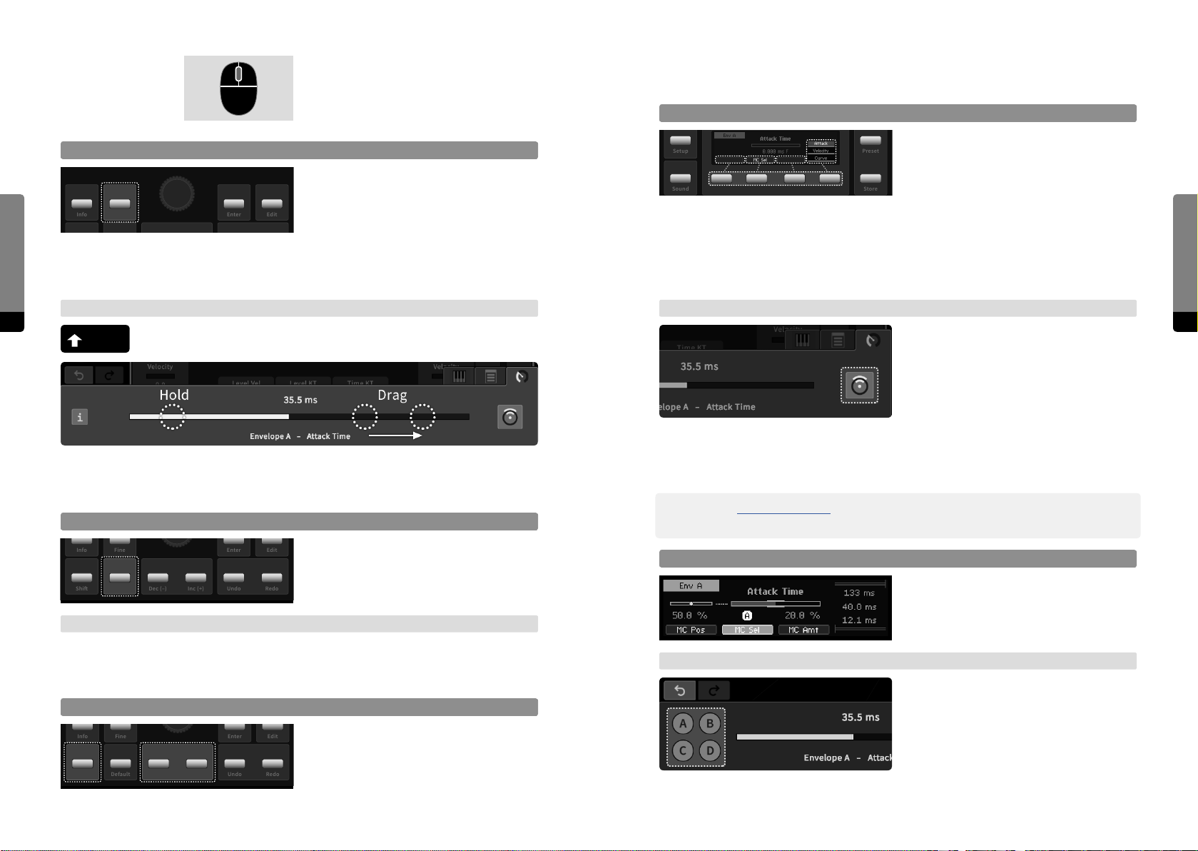
If the external device features a mouse,
Setup
Sound
Preset
Store
the mouse wheel can also be used for
4.3 Editing the Modulation of a Parameter
adjustments when hovering over the slider
in the Parameter tab.
Focus on Modulation Aspects
By default, the parameter’s control position
Adjust Control Position, fine
Setup
The Fine button toggles high resolution
mode for adjustments. An “F” indicator will
User Interfaces
Info
Fine
Enter
appear in the Parameter screen. Usually,
Edit
the Fine mode will be deactivated when
focussing on another parameter. However, the Fine mode can be toggled permanently
as well by holding the Shi button while pressing the Fine button. Now, the Fine mode
remains activated until the Fine button is pressed again.
→ Graphical UI
34 35
While holding down the Shi key, parameter adjustments will be made in
Sound
Macro Control assignment to the parameter. If a Macro Control is assigned, So Buttons
1 and 3 are also available. When focussing on a modulation aspect, So Button 4 is also
available in order to access every modulation aspect. Furthermore, the Panel Unit Display
now shows all modulation aspects. Pressing So Button 1, 2 or 3 twice will set the focus
back to the parameter’s control position.
→ Graphical UI
high resolution mode.
Preset
is in focus and So Button 4 can be used
to cycle through the stack if there is one.
Store
So Button 2 can be used to make a
In the Parameter tab, the modulation icon
can be clicked in order to toggle the focus
on modulation aspects (if a Macro Control
is assigned, all aspects are available). The
horizontal slider represents the aspect in
focus (or the control position by default).
Elements in the main area and the selected
On the slider in the Parameter tab, a pinch gesture (holding one finger while dragging
another) will allow for adjustments in high resolution.
parameter shown in the Parameter tab
indicate their modulation aspects.
User Interfaces
Reset Control Position
Info
Fine
Enter
Press the Default button to recall the
Edit
parameter’s default value.
Shi
Default
Undo
RedoDec (–) Inc (+)
→ Graphical UI
Double click on the element in the main area (if GUI settings allow for it) or the slider in
the Parameter tab in order to recall the currently selected parameter’s default value.
Control Position Edges
Hold the Shi button and press the Dec
Edit
button for minimal, the Inc button for
maximal value.
RedoDec (–) Inc (+)
Shi
Info
Fine
Default
Enter
Undo
߰ In chapter 4.4 Macro Controls, the Fast Mapping method is explained. It provides a quick
way of assigning target parameters to a Macro Control.
MC Selector
Press So Button 2 in order to focus on MC
selector and change the assignment like
adjusting a parameter. Either none (-) or
Macro Control (A, B, C, D) can be assigned.
→ Graphical UI
Change the current MC assignment by
pressing any of the four provided assign-
ment icons (A, B, C, D). Clicking twice on an
icon will clear the assignment. This aspect
will not be in focus on the slider.
Page 19
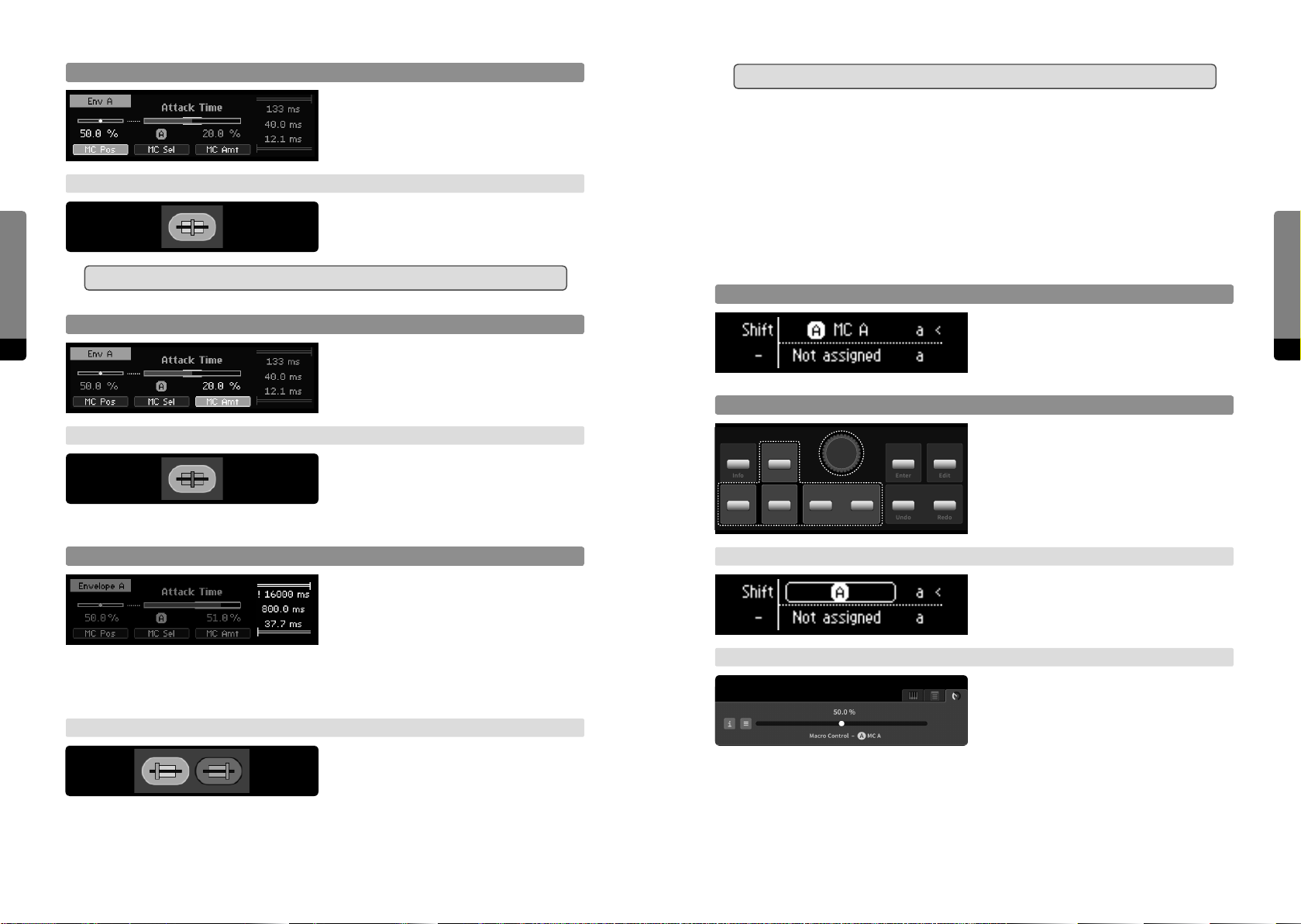
MC Position
߱ These aspects are logically interconnected. Changing one will aect another.
Press So Button 1 in order to focus on MC
position and adjust it like a parameter.
4.4 Macro Controls
→ Graphical UI
The most common practice of using Macro Controls would be the modulation mechanism during user performance, accessible via the Hardware Sources.
4.4.1 Editing a Macro Control
User Interfaces
Click on the MC position icon in order to
focus on MC position and adjust it like a
parameter on the slider.
߱ This will cause a modulation and may aect other parameters as well.
Ribbons in Play Mode
MC Amount
36 37
Press So Button 3 in order to focus on
MC amount and adjust it like a parameter.
In Play mode, Ribbons assigned to Macro
Controls will be operable. Use Mode button
to switch modes.
The modulation range will be indicated
separately, next to the slider.
→ Graphical UI
Click on MC amount icon in order to focus
on MC amount and adjust it like a parame-
Adjust Macro Control Position
Info
Fine
Enter
Adjust the selected Macro Control position
like adjusting a parameter.
Edit
ter on the slider. The modulation range will
be indicated separately, next to the slider and on the main area element.
Modulation Range Aspects
Pressing So Button 4 moves the focus to
the rightmost stack of modulation range
aspects and cycles it. The selected aspect
Default
→ Base Unit
Undo
RedoDec (–) Inc (+)
In Edit mode, Ribbon 1 can be used to
edit the selected Macro Control. Use Mode
button to switch modes.
Shi
can be adjusted like a parameter. Provided
aspects are the modulation range upper limit, the (current) control position and the
modulation range lower limit. When either the upper or lower limit exceed the parameter
range, clipping is indicated by an exclamation mark.
→ Graphical UI
Click on MC Lower Limit or MC Upper Limit
→ Graphical UI
In the Parameter tab, all parameter aspects
of the selected Macro Control are provided. Adjust Macro Control position like a
parameter.
icon in order to focus on modulation range
aspect and change it like adjusting a parameter. The control position is in focus when no aspect is selected. When either the upper or
lower limit exceed the parameter range, clipping is indicated by an exclamation mark.
User Interfaces
Page 20
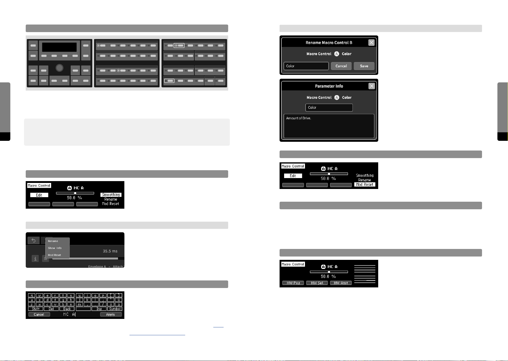
Fast Mapping (Panel Unit only)
→ Graphical UI
A rename dialog appears and the label can
be edited with mouse and keyboard.
Macro Controls
User Interfaces
When the Selection button of a potential target parameter is pressed while the Selection
The info window appears and the info text
can be edited with mouse and keyboard.
button of a Macro Control is held, the assignment can easily be switched on or o. This
only works for target parameters on top of the stack.
߰ This method only handles the actual mapping of target parameters to a Macro Control.
38 39
Modulation amounts have to be adjusted by focussing on each parameter. However, the
modulation amounts are preserved and will recall the last value they were adjusted to.
User Interfaces
4.4.2 Macro Control Properties
Focus on Macro Control Properties
→ Graphical UI
Rename and edit Macro Control Info
Press the Edit button in order to focus on
properties, provided by a stack on the right.
The stack can be cycled with So Button4.
When pressing the Enter button, the
selected property will be available in focus.
In the Parameter tab, a menu icon can be
clicked. In the main area, a right click on a
Macro Control element will also invoke a
context menu providing access to Macro
Control properties.
The Rename screen provides a mechanism
in order to edit the label or info text of a
selected Macro Control. So Button1 can-
cels the process, So Button4 confirms
and applies the process (see chapter 4.10
The Rename Mechanism for further details).
Mod Reset (clear Target Assignments)
Assignments to target parameters of a
selected Macro Control will be reset.
Adjust Macro Control Smoothing Time
not yet implemented
4.4.3 Assigning a Macro Control to Hardware Sources
Focus on Assignment Aspects
By default, the Macro Control position is
in focus. So Buttons 1 to 4 provide focus
navigation, pressing a button twice will
return to the default focus. One Hardware
Source can be selected, and its eect on the Macro Control can be edited. When Ribbon1
is in Edit mode, the selected aspect can be edited there as well (but selection is only
available on the Panel Unit).
Page 21
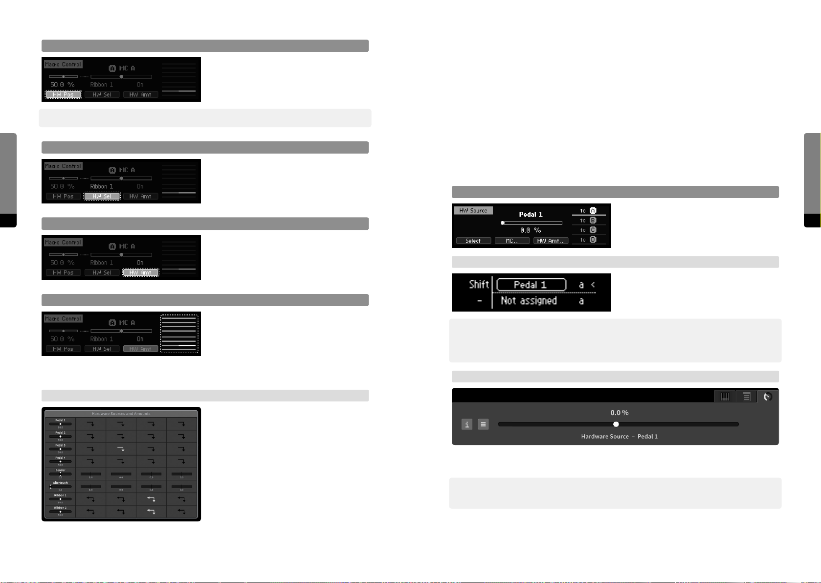
HW Source Position
Press So Button 1 in order to focus on the
currently selected Hardware Source and
adjust its position like a parameter.
߰ This will cause a modulation and may aect other Macro Controls and parameters as well.
User Interfaces
40 41
HW Source Selector
Press So Button 2 in order to focus on
the Hardware Source selector. One of the
eight Hardware Sources can be selected by
adjusting the selector like a parameter.
HW Source Amount
Press So Button 3 in order to focus on the
amount of the currently selected Hardware
Source on the selected Macro Control.
Adjust the amount like a parameter.
HW Source Selection Stack
Pressing So Button 4 moves the focus to
the rightmost stack of Hardware Sources
and cycles it. The eight sliders indicate the
amounts of each Hardware Source on the
selected Macro Control. The selected element of the stack represents the corresponding
amount and can be adjusted like a parameter.
4.5 Hardware Sources
The most common practice of using Hardware Sources would be the modulation
mechanism during user performance, passing movements via Macro Controls to target
parameters.
However, Hardware Sources are available and usable like ordinary parameters. Keep
in mind that adjusting Hardware Sources will cause a modulation, potentially aecting
Macro Controls and target parameters.
4.5.1 Editing a Hardware Source
Adjust Hardware Source Position
Adjust selected Hardware Source position
like adjusting a parameter.
Using a Hardware Source has the same
eect as editing the value in the display.
→ Base Unit
In Edit mode, Ribbon 1 can be used to edit
the selected Hardware Source. Use Mode
button to switch modes.
߰ This will cause a modulation and may aect Macro Controls and target parameters. The
source’s return behavior will be simulated when the screen changes, as indicated by an
exclamation mark next to the value in the display.
→ Graphical UI
User Interfaces
→ Graphical UI
The top-center parameter group „Hardware
Sources and Amounts“ provides access to
all Hardware Sources and their amounts on
Macro Controls, represented as a modu-
lation matrix. Items of interest can be
selected and adjusted like a parameter.
In the Parameter tab, all parameter aspects of the selected Hardware Source are provided.
Adjust the position like a parameter.
߰ This will cause a modulation and may aect Macro Controls and target parameters. The
source’s return behavior will be simulated when releasing the element.
Page 22
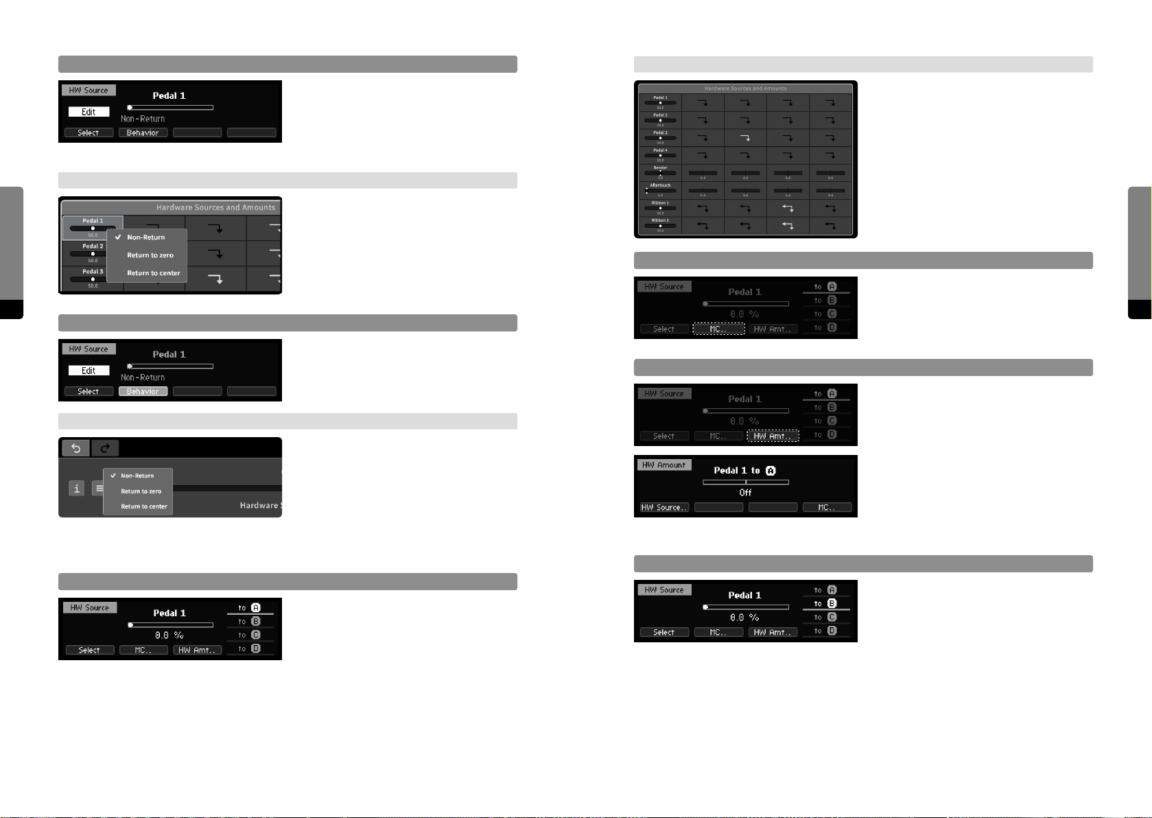
→ Graphical UI
The top-center parameter group „Hardware
Sources and Amounts“ provides access to
all Hardware Sources and their amounts
on Macro Controls, represented as a
modulation matrix. Items of interest can be
selected and adjusted like a parameter.
User Interfaces
Focus on Hardware Source Properties
For Pedals and Ribbons, the return behav-
ior can be edited. Pressing Edit button
when a Hardware Source is selected will
redirect to the Edit screen. Use So But-
tons to select one of the provided aspects.
→ Graphical UI
In the main area, a right click on a Hard-
ware Source element will invoke a context
menu providing access to the properties.
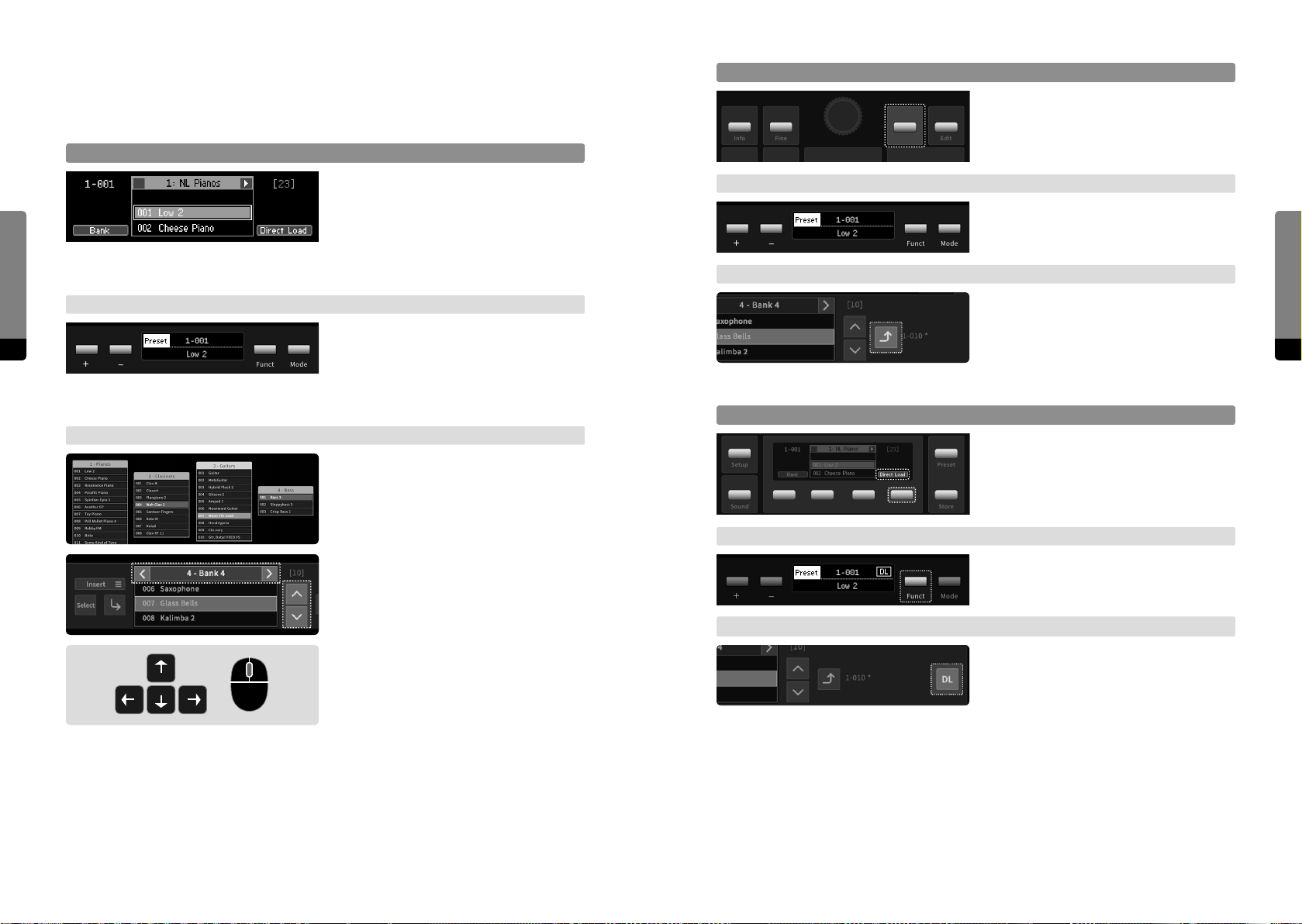
Macro Control Selector
Pressing So Button 2 will redirect to the
42 43
currently associated Macro Control.
Edit Return Behavior
Edit the return behavior like adjusting a
parameter. Returning behavior allows Hard-
ware Source amounts to Macro Controls to
be continuous.
→ Graphical UI
The context menu provides available return
behaviors to select. Returning behavior
allows Hardware Source amounts to Macro
Controls to be continuous.
HW Source Amount
Pressing So Button 3 will redirect to the
Hardware Amount screen, showing the
amount of the currently selected Hardware
Source on the currently associated Macro
Control. The amount can be edited like
adjusting a parameter. Pressing So
Button 1 will redirect to the Hardware
Source, So Button 4 will redirect to the
Macro Control.
4.5.3 Mapping a Hardware Source to Macro Controls
MC Target Selection Stack
Focus on Assignment Aspects
By default, the Hardware Source position is
in focus. So Buttons 1 to 4 provide focus
navigation, pressing a button twice will
return to the default focus. One Hardware
Source can be selected, and its eect on
one Macro Control can be edited.
Pressing So Button 4 will cycle through
the rightmost stack of Macro Controls in
order to change the current association.
User Interfaces
Page 23
Setup
Sound
Preset
Store
4.6 Presets
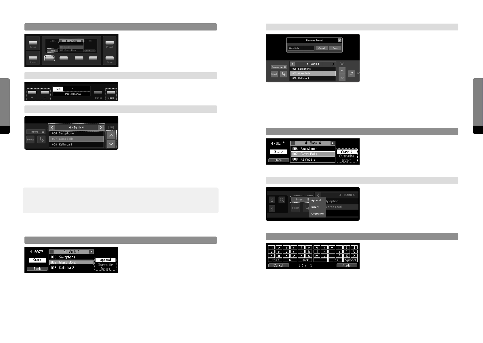
Loading a Preset
On the Panel Unit press the Enter button in
4.6.1 Loading a Preset
Info
Fine
Enter
order to load the selected preset.
Edit
Preset Navigation
User Interfaces
Press the Preset button in order to focus
on the Preset screen. The Encoder as well
as the Inc and Dec buttons will navigate
through the current Bank. So Buttons
→ Base Unit
On the Base Unit press the Funct button in
order to load the selected preset.
2 and 3 navigate banks. The selection is
indicated by a rectangle.
→ Base Unit
The Base Unit Control Panel can be set in
44 45
Preset mode by the Mode button. Using
+ and – buttons will navigate through the
→ Graphical UI
On the Graphical UI the Preset tab provides
a Load icon in order to load the currently
selected preset. Or click on a bank element
twice.
current bank. Both Ribbons will remain in
Play mode.
→ Graphical UI
In the main area, every bank is available
Direct Load
Setup
On the Panel Unit press the So Button 4
in order to toggle the Direct Load option.
Preset
and can be dragged on any position. If
expanded, presets can be selected by
Sound
Store
clicking.
→ Base Unit
In the Preset tab, the currently selected
bank can be navigated by clicking on the
On the Base Unit hold the Funct button for
a second to toggle the Direct Load option.
corresponding navigation icons.
User Interfaces
The arrow keys can be used to navigate
presets (up, down) and banks (le, right).
If the external device features a mouse, the
mouse wheel can also be used for navi-
gating the currently selected bank in the
Preset tab when hovering it.
→ Graphical UI
On the Graphical UI press the Direct Load
icon in the Preset tab in order to toggle the
Direct Load option.
Page 24
→ Graphical UI
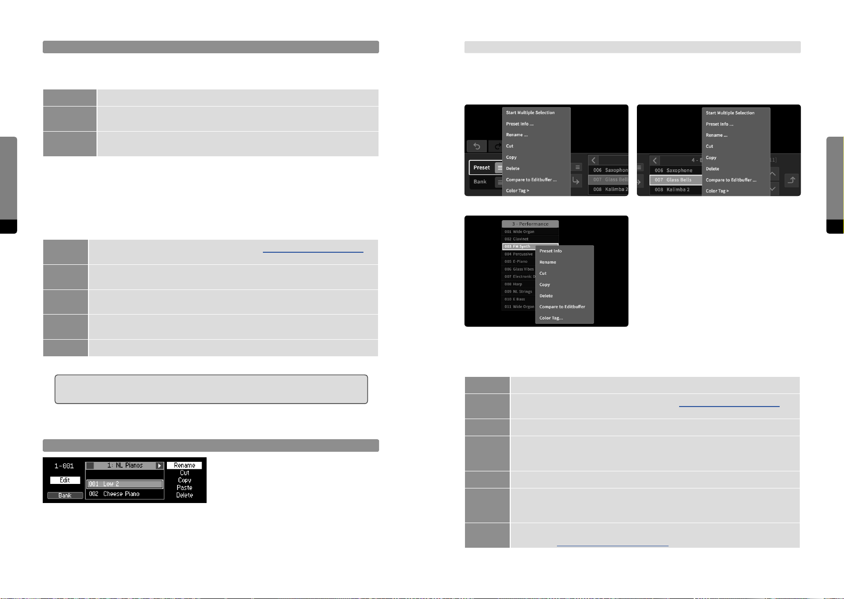
The Preset tab provides a Store icon. Clicking on or touching it will store the preset in
the currently selected bank at the current
position, according to the Store method
(see below). The additional Select button
will start the Store Select mode and a bank
and position can be chosen (without loading any preset), then the preset can be stored at the desired location (disabling the Store
Select mode), according to the Store method (see below). Another way of storing a preset
in a particular bank or position is simply dragging and dropping the Store icon to the
desired location (the Store Select mode and Store method can be ignored in this case).
User Interfaces
Bank Navigation
Setup
Sound
→ Base Unit
→ Graphical UI
On the Panel Unit press So Button 1 in
order to focus on banks and navigate them
Preset
instead. So Buttons 2 and 3 will navigate
presets now.
Store
On the Base Unit Switch to Bank mode by
the Mode button. Using + and – buttons
will navigate banks.
In the main area of the Graphical UI the
46 47
as described.) In the main area the bank selection updates when clicking/touching on a
preset of a floating bank, loading the preset and its parent bank will be selected. A click
or touch gesture on a floating bank header selects the bank as well and the last selected
preset of this bank will be loaded.
߰ The Direct Load option will be indicated on each interface and loads a selected preset
directly. The Panel Unit Display and the Graphical User Interface also show the preset
bank selection updates when loading a
preset. In the Preset tab, banks can be
navigated by the corresponding navigation
icons. (The arrow keys can be used as well,
Store Method
So Button 4 provides three available
Store methods in the rightmost stack and
cycles it. Pressing the Enter button applies
the process, pressing the Store button
again dismisses it.
→ Graphical UI
The Store method can be selected in the
Preset tab, above the store icon.
count of a selected bank (in brackets) and the current bank-preset-number.
User Interfaces
4.6.2 Storing a Preset
Store Select
Press the Store button in order to focus on
the Store screen and start the Store Select
mode. The store position and bank can be
adjusted by preset and bank navigation (as
described in chapter 4.6.1 Loading a Preset). The process can be canceled by pressing the
Store button again, pressing the Enter button on the other hand will complete the Store
process, storing the preset at the desired location according to the Store method (see
below).
Preset Naming
If the preset is considered “new”, the
Rename screen (window) will appear,
requesting a name for the preset.
Page 25
User Interfaces
Store Methods
The store position will be finally influenced by the chosen store method, which can be
one of the following three:
Append The preset will be stored at the end of the currently selected bank.
Overwrite
Insert
The preset will be stored at the current position in the currently selected bank,
overwriting the existing preset.
The preset will be stored behind the current position in the currently selected
bank.
→ Graphical UI
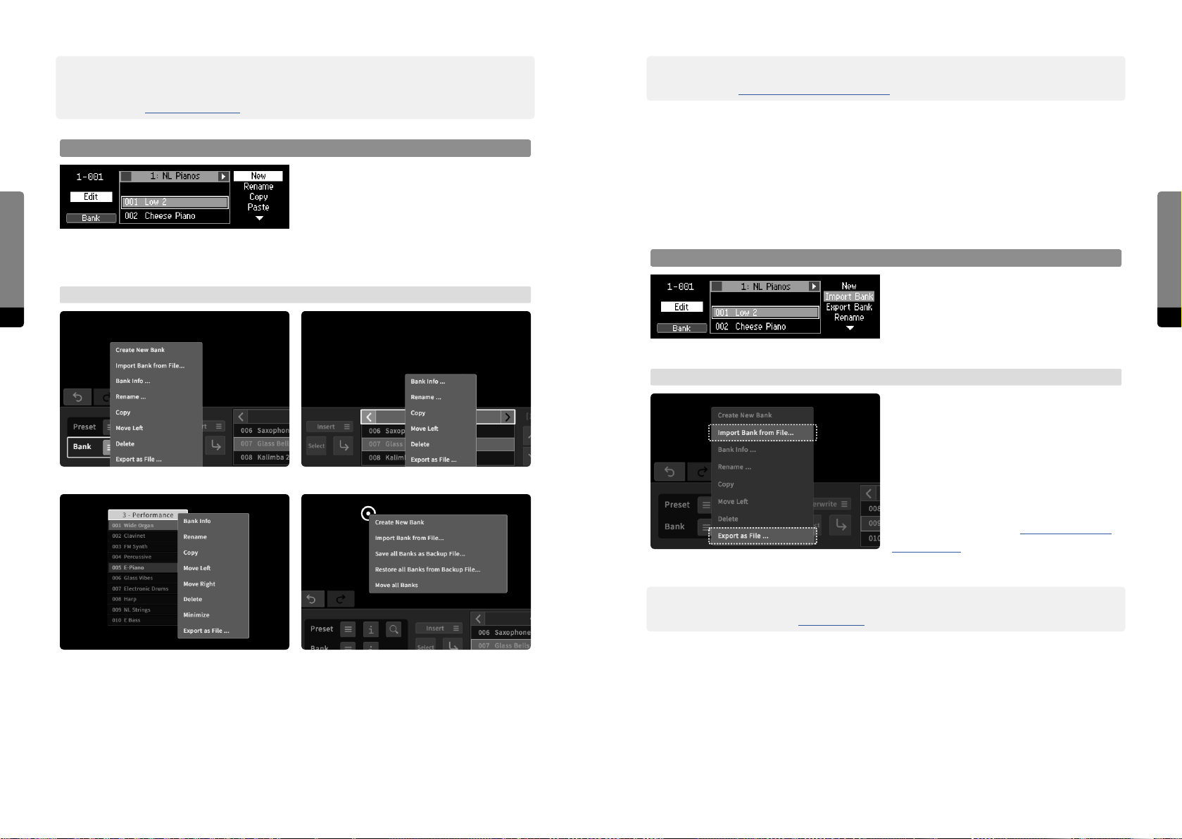
In the Preset tab, a Preset menu button is provided. Clicking on this button or right-clicking (long touch gesture) on a preset element in a (floating) bank invokes the context
menu, providing access to all aspects.
4.6.3 Editing Presets and Banks
48 49
Common Preset editing actions are listed in the table below:
Rename
Cut
Copy
Paste
Delete The selected preset(s) will be deleted from the bank.
The selected preset can be renamed (see chapter 4.10 The Rename Mechanism
for details).
The selected preset will be moved into the clipboard (being deleted at the current
position).
The selected preset(s) will be copied into the clipboard, ready to be pasted at any
time.
Once a preset was copied or cut into the clipboard, this option will become available. The copied preset will be inserted behind the currently selected preset.
Preset Menu 1: Preset tab > Preset button Preset Menu 2: Preset tab > preset list
Preset Menu 3: floating bank > preset entry
Common Bank editing actions are listed in the table below:
߱ When deleting all presets of a bank at once from the Graphical User Interface, a
Dialog window will appear, asking if the bank should be deleted as well.
Preset Edit Mode
When the Preset screen is in focus, pressing
the Edit button invokes a menu, represented in the rightmost stack. Cycle the
stack by pressing So Button 4 in order to
select a menu entry and press the Enter button in order to focus on an aspect. Press the
Edit button again to return to the Preset screen.
New A new bank will be created.
Rename
Copy The selected bank will be copied into a temporary buer, ready to be pasted.
Paste
Delete The selected bank will be deleted.
Move
le/right
Import/
Export
The selected bank can be renamed (see chapter 4.10 The Rename Mechanism for
details).
Once a bank was copied into the clipboard, this option will become available.
߱
The copied bank will be appended as a new bank. This mechanism is not fully
developed yet. For more information, refer to the separate “Known Issues” document.
The bank number (position in the bank list, visible in the Preset screen and Preset
tab) can be altered by moving it le (decreasing the position) or right (increasing
the position).
Single Banks can be transferred from and to external devices.
(see chapter 4.6.4 Importing/Exporting Banks for more details) .
User Interfaces
Page 26
߰ The Graphical User Interface provides another way of moving a bank via the Bank Info
window, where the bank number (position in the bank list) can be adjusted directly
(see chapter 4.7 Contextual Info for more details).
߰ On the Graphical User Interface, more edits on banks are possible
(see chapter 4.15 Graphical UI Functionality for further details).
Bank Edit Mode
4.6.4 Importing/Exporting Banks
The C15 provides two ways of transferring (importing, exporting) single banks in order to
manage big preset collections. When importing a bank, the bank will not be selected and
no preset will be loaded.
User Interfaces
When the Bank screen is in focus, pressing
the Edit button invokes a menu, represented in the rightmost stack. Cycle the
stack by pressing So Button 4 in order to
select a menu entry and press the Enter button in order to focus on an aspect. Press the
Edit button again to return to the Preset screen.
Import and Export on USB stick
When a USB stick is connected, the
→ Graphical UI
50 51
selected bank can be exported to it by
using the Export option. Any bank present
on the USB stick can be selected and
imported by using the Import option.
→ Graphical UI
The bank menu provides an option to save
the current bank as a file, which will be
downloaded on the external device. The
menu also includes an option to import a
Bank Menu 1: Preset tab > Bank button Bank Menu 2: Preset tab > bank header
particular bank from a file present on the
external device, which can be selected
and uploaded. Other Bank context menus
(as explained in chapter 4.15 Graphical UI
Functionality) will also oer import and
export options.
User Interfaces
Bank Menu 3: floating bank header
Bank Menu 4: main area background
The Graphical User Interface provides two menus for editing banks. There is a global
menu (invoked by a right-click / long touch gesture on the background) and a local menu
for banks (provided by a bank menu icon in the Preset tab or by a right-click / long touch
gesture on any bank header).
߰ The process of transferring multiple banks can be further simplified by the C15 backup
capabilities (see chapter 4.13 Backups for more details).
Page 27
4.6.5 Locking
In some situations, it may be useful to load only specific parts of a preset while leaving
other parts as they are. This can be achieved by using the Lock mechanism, which can
lock particular parameter groups and prevent the contained parameters from being
overwritten by a preset recall or sound manipulations. Parameters of locked groups can
still be edited, though.
User Interfaces
߰ Currently, only whole groups can be locked, but a parameter-specific Lock mechanism is
intended for the future.
Locking a Parameter Group
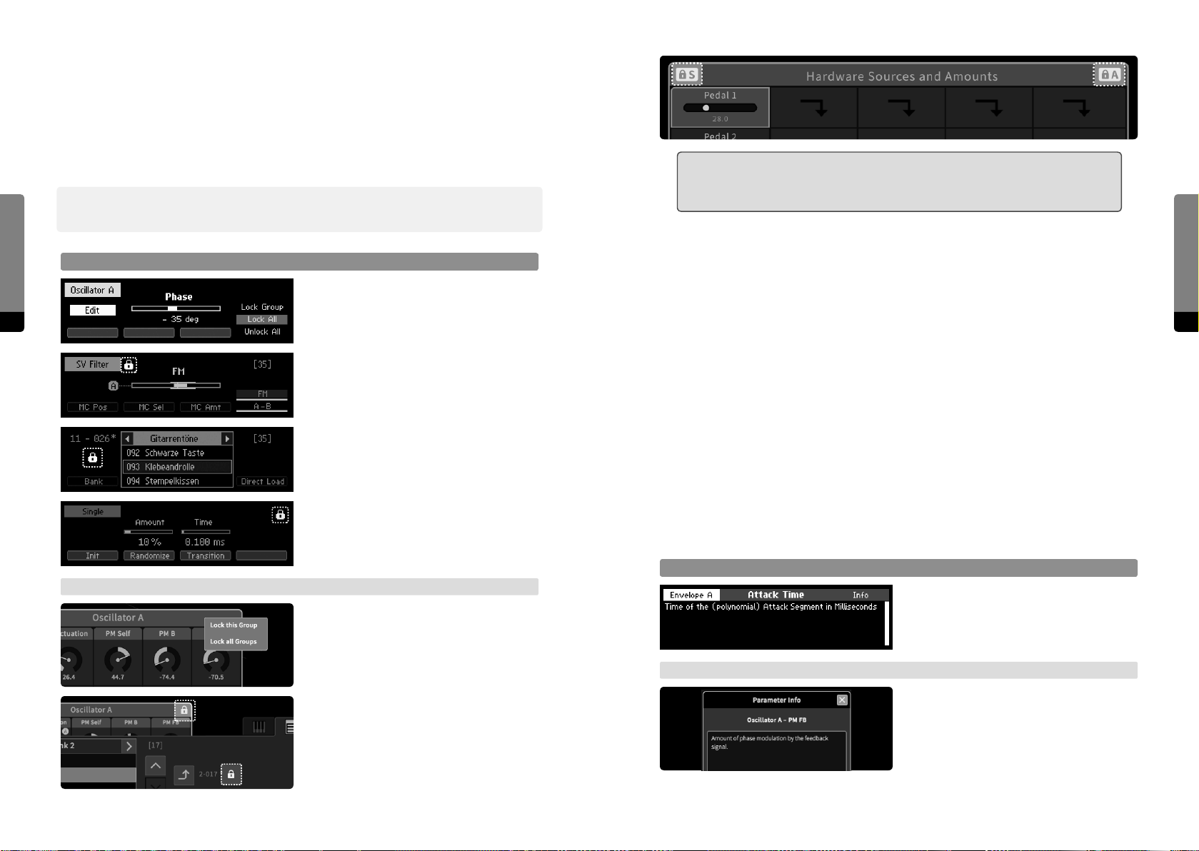
In the Parameter screen showing the
currently selected parameter, the Edit
52 53
button provides the lock menu. Individual
lock options can be selected by pressing
So Button 4 and applied by pressing the
Enter button.
Depending on the lock status of the
associated group, the lock options provide
locking the specific group/all groups, or
unlocking the specific group/all groups.
When one or more groups are locked, the
lock symbol is also shown in the Preset and
Sound screens.
߱ Note that Hardware Sources and Hardware Amounts are two separate lockable
groups. In the Graphical User Interface, the header of the “Hardware Sources
and Amounts” group shows two separate lock symbols.
Locking – a practical example
Let’s consider a situation where the user wants to use certain groups of preset A as a
template for other presets (B, C, …), which shall have those group settings as well.
Useful scenarios may be the Hardware Sources and their Amounts on Macro Controls, or
the whole eect chain. In a few steps, the particular groups of preset A can be copied to
the other presets:
1. Load preset A (the template preset)
2. Activate lock on the corresponding groups (that shall be transferred to the other
presets)
3. Load preset B (the locked groups still remain as defined by preset A)
4. Save preset B (making the template transfer persistent)
5. Load and then save preset C (repeating the process, the locked groups still remain as
defined by preset A), et cetera
4.7 Contextual Info
User Interfaces
→ Graphical UI
A right click or long touch gesture on a
particular group header invokes the lock
menu. Depending on the lock status of the
associated group, the lock options provide
locking the specific group/all groups, or
unlocking the specific group/all groups.
When one or more groups are locked, the
lock symbol is also shown in the Preset and
Sound tabs.
Parameter Info
When a parameter is selected, the Info
button invokes the Info screen, showing the
current parameter’s description.
→ Graphical UI
In the Parameter tab, an Info icon is
provided, toggling an Info window showing
the description of the currently selected
parameter. The window will update when
selecting another parameter.
Page 28
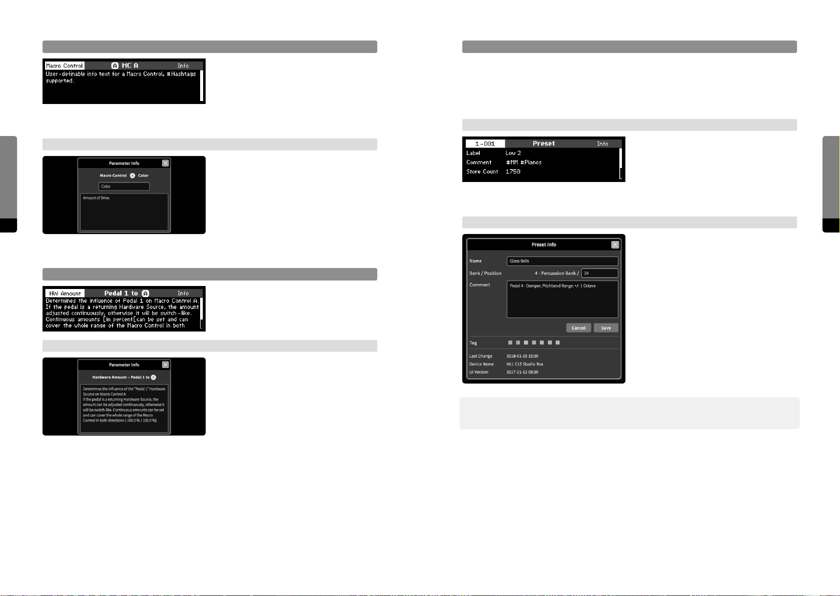
Macro Control Info
When a Macro Control is selected, the Info
button invokes the Info screen, showing the
description of the currently selected Macro
Control. When pressing the Edit button, the
Preset Info
Presets contain a collection of metadata, some of which can be edited. The metadata
collection includes: a reference to the parent bank name, the preset position within the
parent bank, the preset name, a comment text, a color tag and information about the last
saved change (date, device name, ui version).
user-definable info text can be edited in the
Rename screen.
User Interfaces
→ Graphical UI
The Info icon in the Parameter tab works
accordingly when selecting a Macro
Control, context menus for the main area
elements are also provided. The provided Info window allows for edits on the
54 55
user-definable info text.
→ Panel Unit
When in the Preset screen, the Info button
invokes the Info screen for the currently
selected preset. The screen can be scrolled
by the Encoder or Inc, Dec buttons. When
pressing the Edit button, the comment text
can be edited in the Rename screen.
→ Graphical UI
The preset Info window can be made visi-
ble when clicking on the Preset Info icon in
the Preset tab or by a right click on a preset
Hardware Source/Amount Info
When the focus is on a Hardware Source or
on a Hardware Amount to a Macro Control,
the Info button provides the Info screen
according to the item in focus.
→ Graphical UI
within a bank, selecting the „show info“
option. The window can be le visible and
will update when loading other presets.
In addition, the global View menu also
provides a visibility option for the Preset
Info window.
The Info window will display the description of a selected Hardware Source
or Amount as described for ordinary
parameters.
߰ In the Graphical User Interface, the Preset Info Window allows for editing the preset
number (position in the bank), name, comment and color tag.
User Interfaces
Page 29
Bank Info
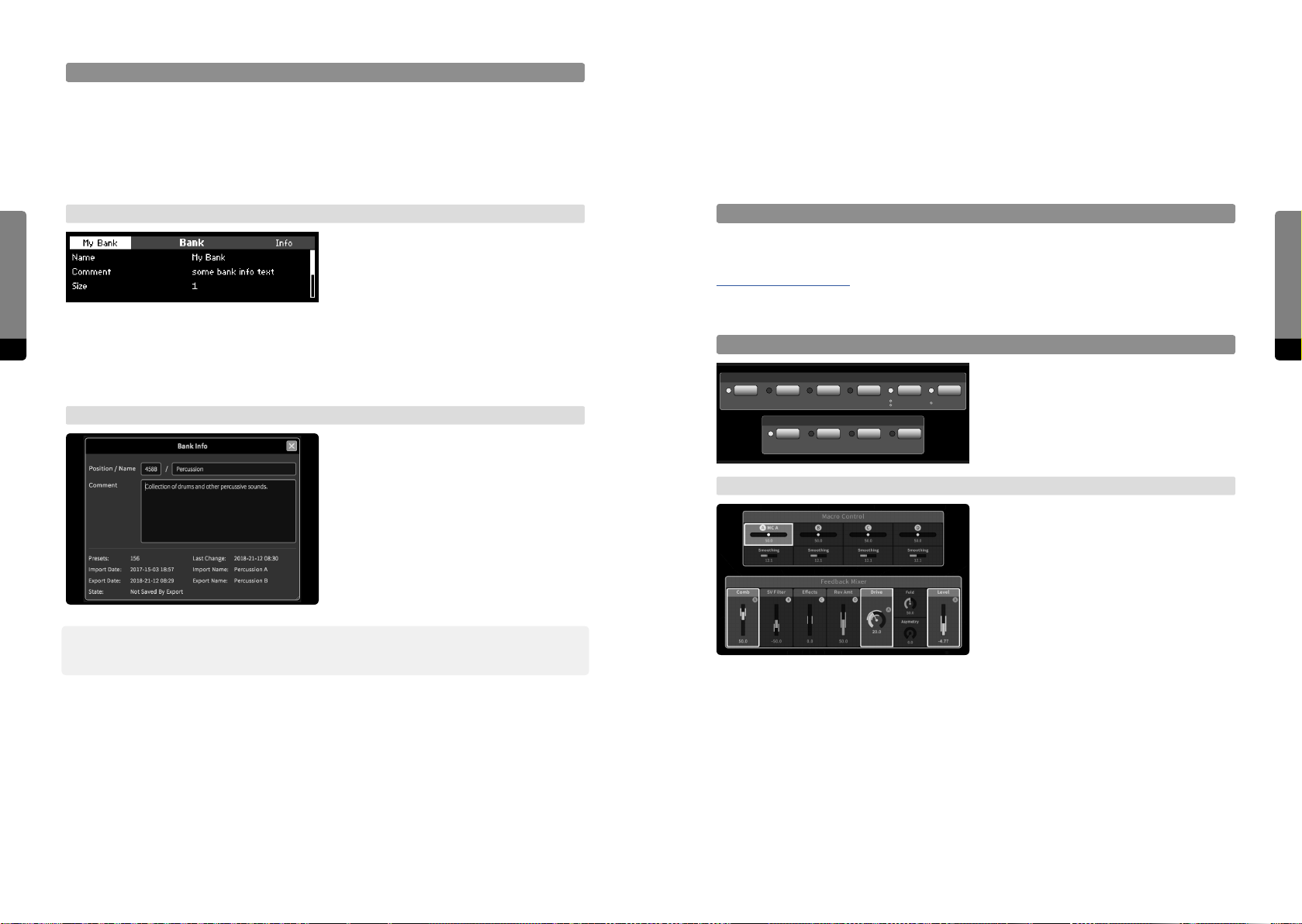
Banks contain a collection of metadata, some of which can be edited. The metadata collection includes: the bank number (position in the bank list), the bank name, a comment
text, the bank size (number of contained presets), a state (indicating if unsaved changes
occurred since the last export) as well as information about the last change (date), import
(date, filename) and export (date, filename).
4.8 Overviews
There are dierent Overviews provided on the Panel Unit, enabling the user to quickly
get an impression of the inner workings of a particular sound, just by a brief glance at the
Parameter Panels. Without listening to the sound or studying parameter values, certain
assumptions on signal flow and modulation assignments can be easily made.
User Interfaces
→ Panel Unit
When in the Bank screen (available when
pressing So Button 1 while in the Preset
screen), the Info button invokes the Info
screen for the currently selected bank. The
Active Overview (Panel Unit only)
At any time, when the Preset screen is in focus, active overview will be provided. Signalflow related parameters that are not zero (‘active’) will have lit LEDs (see chapter
9.Parameter Reference for further details). When Macro Controls are mapped to at least
one parameter, they will show lit LEDs as well.
screen can be scrolled by the Encoder or
56 57
Inc, Dec buttons. When pressing the Edit
button, the comment text can be edited in
the Rename screen.
→ Graphical UI
The bank Info window can be made visible
MC Target Overview
Feedback Mixer
Comb S.V.F. Eects Reverb Drive Level
Macro Controls
When a Macro Control is selected, all
assigned target parameters will show their
assignment by blinking LEDs.
when clicking on the Bank Info icon in the
Preset tab or by selecting „show info“ in the
context menu provided by the bank menu
icon or in other bank context menus. The
window can be le visible and will update
when selecting other banks. In addition,
the global View menu also provides a
→ Graphical UI
When a Macro Control is selected, it will be
surrounded by a red rectangle. All assigned
target parameters show their assignment
by surrounding red rectangles as well.
visibility option for the Bank Info window.
߰ In the Graphical User Interface, the Bank Info Window allows for editing the bank number
(position in the bank list), name and comment text.
User Interfaces
Page 30
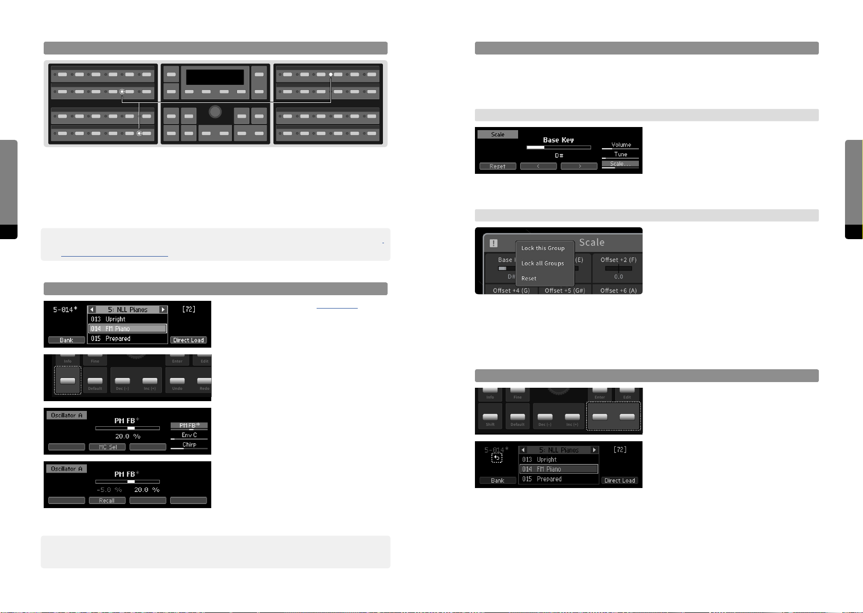
Signal Flow Overview (Panel Unit only)
Scale Overview
In order to quickly notice if any keys have an individual tuning (as controlled by the Scale
Group Oset parameters), the Scale Group provides an Overview, showing if active (nonzero) oset parameters are present.
→ Panel Unit
The active state is indicated by a high-
User Interfaces
When selecting a parameter of a particular group, blinking LEDs on the Panel Unit show
where the output signal of this group is applied further in the signal chain. (If, for example,
a parameter of the Feedback Mixer is selected, the PM FB and FB Mix parameters of the
Oscillators and Shapers will have blinking LEDs, if they are unequal to zero - indicating
that the output signal of the Feedback Mixer is applied in these particular sections.
58 59
߰ The Signal Flow indicator is optional and can be disabled in the Setup Menu (see chapter
→ Graphical UI
6.Setup (C15 System Settings) for more details).
lighted bar for the Scale Group in the
selection stack, and when the Scale Group
is selected, a “Reset” option is provided
by So Button 1, which will set all active
Oset parameters to zero.
The active state is indicated by an exclama-
tion mark in the Scale Group header, and
a “Reset” option is provided by the header
context menu, which will set all active
Change Overview (Panel Unit only)
Oset parameters to zero.
As mentioned in chapter 3.5 Presets, the
Preset screen will indicate changes (user
edits) to a loaded preset by showing an
4.9 The Undo Mechanism
Simple Undo/Redo
Info
Shi
Fine
Default
Enter
Undo
The current, active branch can be navi-
Edit
gated by using the Undo and Redo buttons
in the Edit Panel, recalling the correspond-
RedoDec (–) Inc (+)
ing state immediately.
When the Undo button was pressed, an
Undo indicator will appear in the Preset
screen, showing that the Redo option is
available. The Parameter screen also shows
the Undo indicator, as long as no other
parameter is selected.
Info
Shi
Fine
Default
Enter
Undo
asterisk behind the unique number.
When changes occured to a loaded preset,
Edit
holding the Shi button while in the Preset
screen will show the Change Overview on
RedoDec (–) Inc (+)
the Panel Unit, as changed parameters will
now have blinking LEDs.
When a changed parameter is selected and
visible in the Parameter screen, an asterisk
behind its label will be shown as well.
Holding the Shi button now will redirect
to the Compare screen, showing the loaded
(initial) and changed (edited) positions
simultaneaously. Both can be recalled by
using So Buttons 2 and 3.
User Interfaces
߰ For now, the Change Overview and Compare screen are only available for parameter
positions. Modulation amounts and MC selectors are planned to be integrated as well.
Page 31
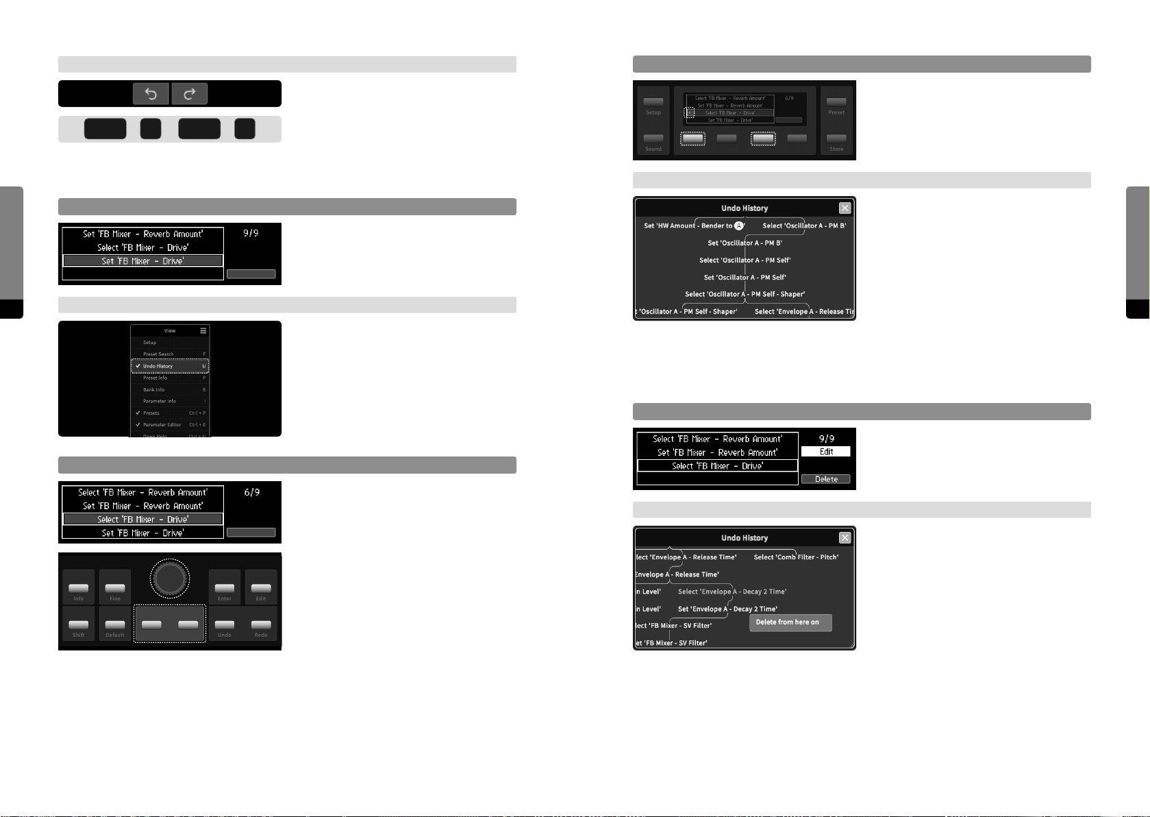
User Interfaces
Z
Y
→ Graphical UI
The current, active branch can be navigated by using the Undo and Redo icons
ctrl
+ +
ctrl
above the tab area, recalling the corre-
sponding state immediately. The icons
indicate which Undo options are available, as shown by their color. Alternatively, the
usual keyboard shortcuts for undo and redo can be used.
Focus on Undo History
Pressing both Undo and Redo buttons at
once will invoke the Undo screen, providing
full navigation of the undo history.
Navigate Branches
If a branch splits at the current position,
pointy brackets are visible on the entry. Use
So Buttons 1 and 3 to switch between
branches. Recalling an entry of an inactive
branch will make it active.
→ Graphical UI
The Undo History window can be scrolled
by drag gestures on the background or the
scrollbar, or by using the mouse wheel. A
simple click on an element will recall the
corresponding state. As all branches of the
tree are visible in this window, the branch
60 61
→ Graphical UI
In the View menu, the Undo History win-
dow can be shown or hidden. It provides
full access on undo-related aspects.
navigation is fully integrated. A right-click
(or long touch gesture) on an element provides a context menu for further options.
The „hide“ option will hide the selected
branch, the other options follow below.
Delete (inactive) Branch
When navigating an inactive branch, press
the Edit button in order to get the delete
Navigate current Branch
Info
Fine
Enter
The Undo screen can only show one
branch of the undo tree. It can be scrolled
by using the Encoder or Inc, Dec buttons.
The current position will be indicated by a
rectangle and can be recalled by pressing
the Enter button.
Edit
→ Graphical UI
option. Pressing So Button 4 will delete
the whole branch.
When the selected element is on an inactive branch, the „delete from here“ option
will be provided. Confirming this option will
delete the whole branch.
User Interfaces
Shi
Default
Undo
RedoDec (–) Inc (+)
Page 32
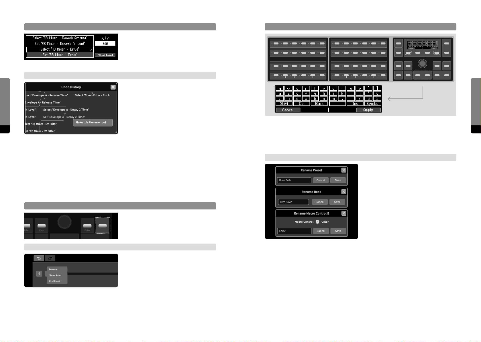
Make Element the new Root
Info
The Rename Screen
When navigating the current, active
User Interfaces
branch, press the Edit button in order to
get the „Make Root“ option. All entries and
branches prior to the current position will
be deleted by pressing So Button 4.
→ Graphical UI
When the selected element is on the cur-
Q W E R T Y
A S D F G H
Z X C V B N
Shift Del Back
U I O P [ ]
J K L ; ‘ Ü
M , . / Ö Ä
Space Ins Symbol
Dec (–) Inc (+)
rent, active branch, the „make this the new
root“ option will be provided. Confirming
this option will delete all elements and
branches prior to the selected element.
When the Rename screen is shown, the two Parameter Selection Panels on the le or
62 63
on the right side of the display can be used as a keyboard, as indicated by the keyboard
layout in the screen. The cursor can be moved by using the Encoder, or the Inc, Dec
buttons. So Button 1 will cancel the process, So Button 4 will apply the process.
User Interfaces
4.10 The Rename Mechanism
Aected Items
Items that can be renamed are the labels and info texts of Macro Controls, as well as
names and comment texts of presets and banks.
Get Rename Option
As previously described, renaming options
will be provided when pressing the Edit
Fine
→ Graphical UI
Enter
Edit
button in the corresponding context.
As previously described, renaming options
will be provided when invoking a context
menu for corresponding items.
→ Graphical UI
When a rename option was called, a dialog
window will appear, containing an entry or
textbox element. Mouse and keyboard on
the external device can be used to rename
the corresponding item. Dialogs provide OK
and Cancel buttons in order to finish the
process accordingly.
Page 33
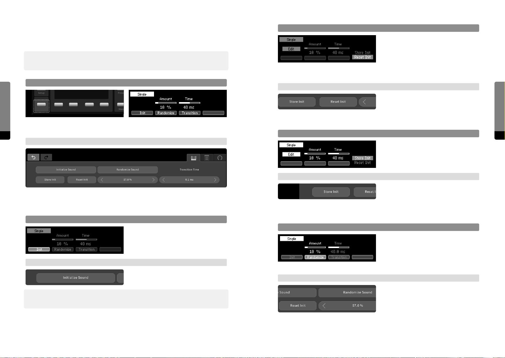
4.11 Sound Manipulation
Preset
Store
Reset Init
Press the Edit button to invoke a menu
The current setting can be further manipulated, aecting all parameters at once.
߰ Note that initializing or randomizing the sound will occur within the „Edit Smoothing Time“,
defined in the system settings. A preset recall on the other hand uses the „Transition Time“.
stack on the right, navigate with So Button 4 and press Enter in order to reset the
Init sound. The factory default settings will
be restored to all parameter default values.
The Init sound will not be loaded, though.
User Interfaces
Focus on Sound Screen
Setup
Sound
→ Graphical UI
When clicking on the „Reset Init“ icon, the
default value of every parameter will be
reset to the factory default settings.
Pressing the Sound button will invoke the Sound screen, providing options to further
64 65
manipulate the current sound or sound transition.
→ Graphical UI
Store Init
The menu stack also provides an option in
order to store the current sound as the new
default settings for all parameters.
→ Graphical UI
When clicking on the „Store Init“ icon, the
The Sound tab provides options to further manipulate the current sound or sound
transition.
default value of every parameter will be
overwritten by the corresponding current
value.
User Interfaces
Init Sound
Press So Button 1 to select and then the
Enter button to recall the Init sound. Every
parameter will load its default value.
→ Graphical UI
When clicking on the „Init Sound“ button,
every parameter will load its default value.
߰ Note that the factory default values for Output Mixer component levels are zero, meaning
that the initial sound is silent.
Randomize
Press So Button 2 in order to focus on the
sound randomization. The amount of the
randomization can be adjusted like editing
a parameter. Press the Enter button in
order to randomize all parameters.
→ Graphical UI
When clicking on the „Randomize Sound“
icon, all parameters will be randomized
according to the randomization amount,
shown below. Use drag gestures on the
amount value in order to change the
amount like adjusting a parameter.
Page 34
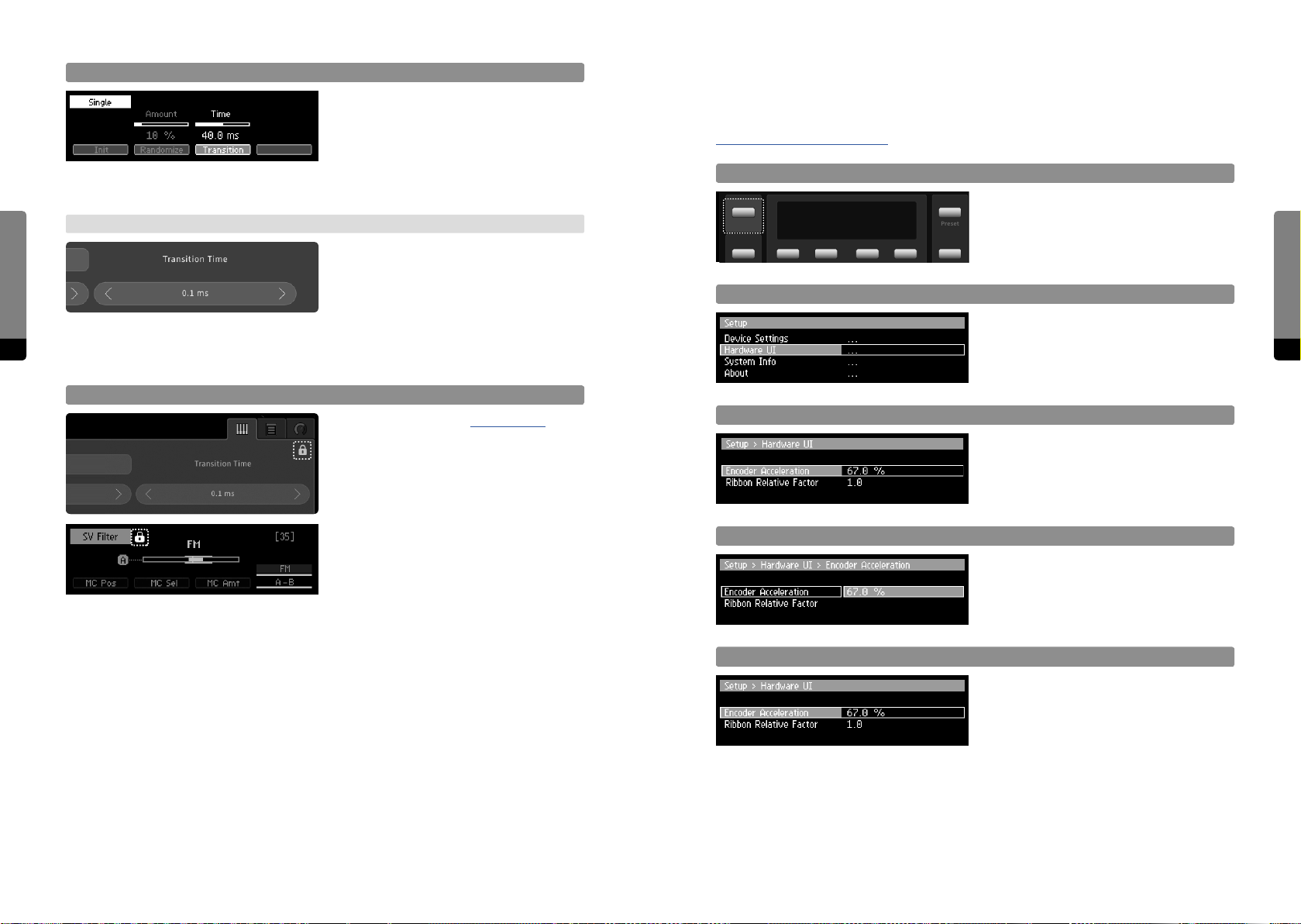
Transition Time
4.12 Setup Navigation
Press So Button 3 in order to focus on
the transition time and adjust it like editing
a parameter. The transition time will be
This section explains the navigation to and within the setup menu. Refer to chapter
6 Setup (C15 System Settings) for a detailed reference.
eective when recalling presets, defining
the smoothing time of the parameters as
they approach their new values.
User Interfaces
→ Graphical UI
Change the transition time by using drag
gestures on the „Transition Time“ value, like
adjusting a parameter. The transition time
will be eective when recalling presets,
defining the smoothing time of the parame-
66 67
ters, approaching their new values.
Focus on Setup Menu
Setup
Scrolling
Press the Setup button in order to invoke
the Setup screen. The menu content is
Preset
organized in dierent levels which can be
entered.
Scroll the menu by using the Encoder or
the Inc, Dec buttons. The position will be
indicated by a highlighted background.
Sound Manipulation and Locking
As described in chapter 4.6.5 Locking,
parameters of locked groups are not
aected by sound manipulations. For
example, randomizing all parameters may
Enter a Submenu/Property
Press the Enter button or So Buttons 1
or 2 in order to enter a submenu or a menu
property, according to the current position.
not be a good idea when considering the
Master, Unison and Scale groups, as the
random change can have too much of an
impact, leading to unwanted, bad sounding
or even harmful results (should the Master
Volume increase considerably). So we rec-
Adjust a Property
When focussing on a property, adjustments
can be done like editing a parameter, by
using the Encoder or the Inc, Dec buttons.
ommend to lock these three groups before
using the randomize function.
Escape a Submenu/Property
So Buttons 3 and 4 can be used to navi-
gate back to the next higher level. When a
property is in focus, the Enter button has
the same eect.
User Interfaces
Page 35
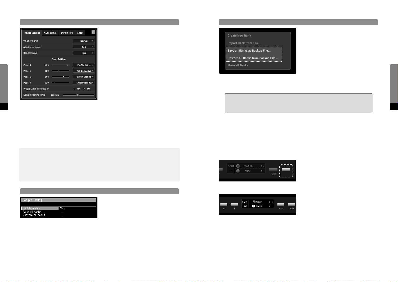
User Interfaces
Setup Window (Graphical UI only)
The topright View menu provides the
„Show/Hide Setup“ option, toggling the
visibility of the Setup window. The menu
content is organized in tabs which can
be focussed. In each tab, the corresponding properties are provided and can be
adjusted (some properties have context
menus, some can be adjusted by drag
gestures, like a parameter).
Saving and Restoring Backups on External Device (Graphical UI only)
The background menu of the Graphical
User Interface provides options for saving
and restoring backups. When „Save all
Banks as Backup File“ is selected, all banks
will be copied into a single file which then
will be downloaded on the external device.
When „Restore all Banks from Backup
File“ is selected, a backup file present on
the external device can be chosen and uploaded. You will find the downloaded file at a
location depending on your browser settings.
߱ Please keep in mind that when restoring from a backup file, all banks currently
68 69
present on the C15 will be lost. We recommend to save a backup file before
restoring in order to maintain all preset data.
4.13 Backups
As previously mentioned, single banks can be imported and exported from an to either
a connected USB stick or the connected external device. In addition, the transfer of all
banks at once is also provided, which allows for fast and easy backups
߰ We recommend creating backups of your banks regularly. Although the C15 can hold an
arbitrary number of banks, it can be helpful to keep the interface clean by not overloading
it with banks, speeding up booting, backup and shutdown processes. Using single backup
files for bank collections may also be helpful for live musicians who may need to load their
presets on a C15.
Saving and Restoring Backups on USB Stick (Panel Unit only)
In the Setup menu of the Hardware User
Interface, the Backup submenu can be
found, providing a Restore and a Save
option. When a USB stick is connected,
pressing the Enter button will allow for
exporting or restoring of backups.
4.14 Base Unit Functionality
Here is a quick recap of the Base Unit functionality, compiling all available features into a
single overview.
The Mode button cycles four distinct
operation modes, which are explained
Funct Mode
transposing the whole instrument (note shi). Pressing a single button will perform an
octave shi, pressing one button while holding the other will perform a semitone shi.
The Funct button switches between absolute and relative behavior for the most recently
used Ribbon (indicated by a pointy bracket).
in the following. The functionality of the
remaining buttons depends on the current
mode.
In Play mode, both Ribbons function as
ordinary Hardware Sources. If they are
assigned to a Macro Control, they will be
operable. The +/- buttons can be used for
User Interfaces
Page 36
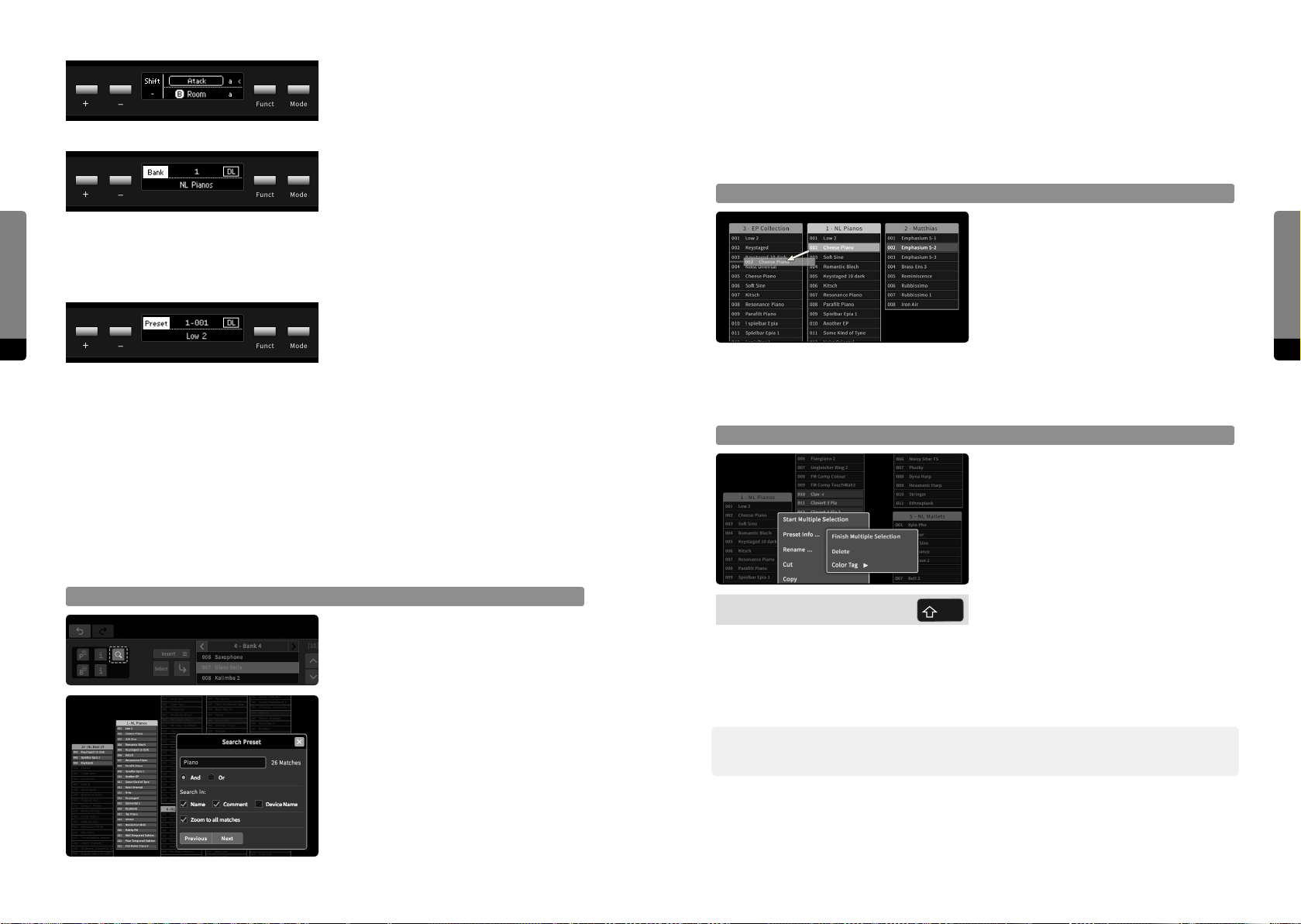
In Edit mode, Ribbon 1 will operate as an
additional parameter editor for the current
parameter focus. The remaining functionality remains as described for the Play mode.
In Bank mode, both Ribbons remain operable as Hardware Sources. The +/- buttons
can be used to navigate banks.
User Interfaces
70 71
The Funct button will serve as a direct load
switch (when held for a second). The last
selected preset of the corresponding bank
will be loaded.
In Preset mode, both Ribbons remain operable as Hardware Sources. The +/- buttons
can be used to navigate presets.
The Funct button will serve as a Load
button (when pressed) or as a direct load
switch (when held for a second).
will set the zoom level of the main area, so that every match is instantly visible. The
success of a search strongly depends on the level of documentation (meaningful preset
names and descriptive comments). Bank information (comments) are not included in
the search. Using hashtags for specific keywords can be a sophisticated method of preset
search and documentation.
Preset Drag and Drop
A selected preset can be dragged on other
positions in a bank, into other banks or
on the background. When it is dropped, it
will move to the new position (if the bank
remains the same), or it will be copied to
the new position (creating a new bank if it
was dropped on the background).
If a preset is dropped directly on another preset (as indicated by a red background), the
other preset will be replaced. In a similar manner, banks can be dragged as well in order
to change their position in the main area, or to copy their contents into other banks.
Multiple Preset Selection
Bank context menus (invoked by a right
4.15 Graphical UI Functionality
There are some more features of the Graphical User Interface, which are not available on
both Base and Panel Unit. Other features are available on both User Interfaces, but are
organized in dierent ways.
Preset Search
All available presets can be searched for
keywords, the search results will be highlighted until the search is canceled. Search
keywords can be logically combined by
setting the logical operator (AND: every
keyword has to match, OR: any keyword
that matches). The search algorithm can
further be specified to include preset
names, preset comments and the device
names where presets originated from (as
the selectable options show in the Search
window). The “Zoom to all matches” option
presets can then be deleted or copied (see context menu), or dragged into any bank at
any position or on the background, creating a new bank containing copies of the selected
presets. The selection of multiple presets can be finished in the context menu or by a click
on the background.
߰ Note that Preset Drag and Drop and Multiple Preset Selection are only available, if the GUI
Settings (explained in the following) allow for context menus and drag and drop.
click or long touch gesture on a bank in
the main area) provide an option to start
and finish the selection of multiple presets.
Alternatively, the Shi key can be used to
hold the Multiple Selection mode. During
multiple selection, presets of any bank can
be added or removed from the selection
(but they will not be loaded). All selected
User Interfaces
Page 37
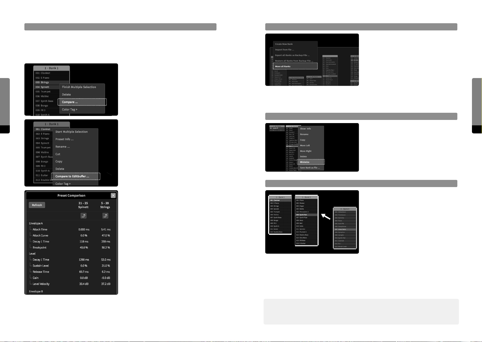
User Interfaces
Preset Compare
Two presets can be compared against each other, examining their individual dierences.
This may be useful for distinguishing several versions of a preset that are only slightly
dierent. Two compare methods are available, as shown in the following:
By using the multiple preset selection
mechanism and selecting two presets, a
context menu entry “Compare ...” will be
available when right-clicking on the selection. The two presets will be compared
against each other.
Move all Banks
There is a shortcut to move all banks at
the same time, provided by the global
context menu (invokedby a right-click or
long touch gesture on the background). If
the „Move all Banks“ option is selected, a
white rectangle will appear, surrounding all
banks. Drag gestures now allow for moving
all banks to another place in the main area.
To stop, re-select the option or click on the
background.
A right-click on any preset will provide a
72 73
“Compare to Editbuer ...” option. The
preset will be compared to a copy of the
Editbuer (the current parameter settings).
The local bank context menu provides an
option to minimize a bank. A double click
on a bank header has the same eect.
When a bank is minimized, it will consume
only a small space, but still provides access
to all contained presets (the access is only
sequential, though).
Docking Banks
Minimize Banks
When starting the compare mechanism by
either method, the Compare window will
appear, showing every parameter or aspect
that diers between the two presets. Equal
parameters or aspects are not visible. Any
of the two presets can be loaded, as provided by a Load icon in the header section
of the window (so, both Presets can be
tested and played without closing the Compare window). When comparing a preset
to the Editbuer, subsequent adjustments
to parameters that change the Editbuer
will not be recognized by the Compare
window automatically. The Refresh button
can be dragged as a whole or docked to larger bank clusters. The top- or lemost bank of
a cluster behaves as the master and will move the whole cluster when dragging it, while
the other banks can be dragged away from the cluster in order to split the group back
into individual parts. Furthermore, when dragging a single bank between two banks of a
cluster, it can be inserted as well.
When dragging banks manually to certain
positions in the main area, they might not
align very well. In order to create an align-
ment, a bank can be docked to another
by dragging it close to other banks. The
bank outlines change, indicating possible
docking targets (top, right, bottom, le) for
the dragged bank. When banks are docked
together, they also behave as a group that
can be used in order to get a new copy of
the current Editbuer, ensuring that the
comparison is up-to-date.
߰ Banks can be docked ontop of each other as a vertical cluster. When minimizing or
maximizing an individual bank, the cluster will maintain the alignment and shi the other
banks accordingly.
User Interfaces
Page 38
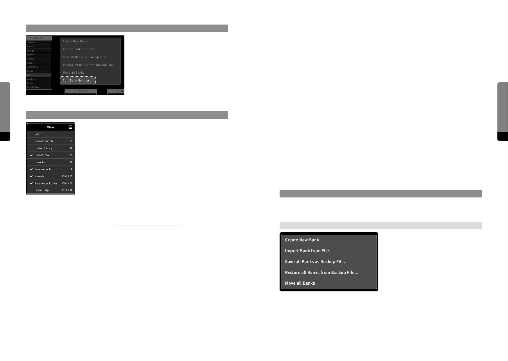
Sort Bank Numbers
The background context menu provides
an option to sort the bank numbers. This
will re-evaluate their order in the bank list,
which is available by sequential access in
the Preset screen or tab. The new order
will be aected by clusters (which will be
User Interfaces
evaluated first), and the bank positions
on the main area or within a cluster (from
upper le to lower right).
The View Menu
The View menu (available in the top-right corner, indicated by a
74 75
menu icon) provides quick access to crucial components of the
Graphical User Interface. The following components can be made
visible or invisible (GUI shortcuts to the components are shown
as well).
Bank Info
Similarly, banks also contain metadata which will be provided by the Bank Info window.
Parameter Info
In addition, specific parameter information will be provided by the Parameter Info
window.
Presets
All the floating banks in the main area can also be shown or hidden, shiing the focus to
the parameters. Nevertheless, all banks still are available in the Preset tab.
Parameter Editor
All parameters in the main area can also be shown or hidden, shiing the focus to presets
and banks. The Parameter tab still provides the opportunity to edit a selected parameter.
However, parameters cannot be selected anymore (the Hardware User Interface still
provides complete access).
Open Help
The C15 User Manual is also available as a separate HTML document, which will open in a
new browser tab.
Context Menus
Setup
When clicking this option, the Setup menu opens in a new window. For more information
about the Setup menu, refer to chapter 6 Setup (C15 System Settings).
Preset Search
As described, presets can be searched for keywords. Click on this option to start a search
task, opening the Search window.
Undo History
All user actions are tracked and can be undone, as provided by Undo and Redo icons
above the tab area. In order to have a complete overview or browse through the history,
the Undo History window can be used, showing all tracked actions in a tree-like structure.
There are several context menus available providing dierent functionalities (according to
the context). They all can be closed by pressing the Escape key.
Background Context Menu
The Background context menu appears
when right-clicking on the background.
Alternatively, a long touch gesture can be
used to invoke the menu. The menu pro-
vides global functionality such as creating
a new bank, importing a bank (from the
external device), saving or restoring back-
ups and moving all banks at once.
Preset Info
Every preset contains metadata, such as a comment text or the creation date, for example. All the preset-relevant information is provided by the Preset Info window.
User Interfaces
Page 39
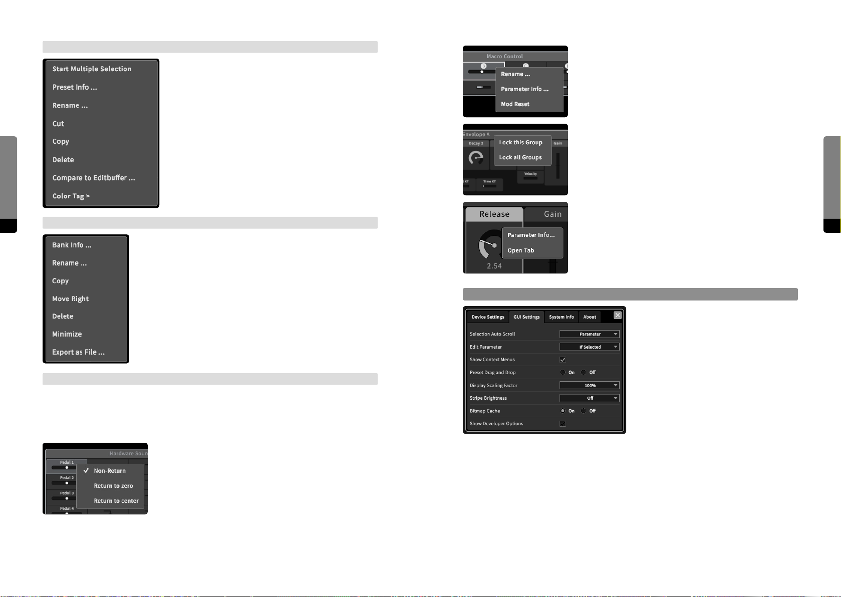
User Interfaces
Preset Context Menu
There are a two ways to invoke the Preset context menu.
In the Preset tab, a menu icon is provided for presets.
In addition, a right click (or long touch gesture) on a
preset (in the Preset tab or in the main area) can also be
used. The menu provides preset-specific functionalities
such as handling multiple preset selection, an option
to show the Preset Info window, a rename option, cut/
copy/paste/delete options for selected presets, the
compare option and a fast way to change the color tag
of selected presets.
Macro Controls provide options for renaming, viewing
the Parameter Info window (showing their user-definable
info text) and resetting (clearing all mappings to target
parameters).
Each group header additionally provides local (aecting
the specific group) and global (aecting all groups) locking
options.
The Parameter context menu provides an option to get the
76 77
Bank Context Menu
The Bank context menu can be invoked by the Bank menu icon
in the Preset tab, or by a right click (or long touch gesture) on
parameter info (by showing the Parameter Info window)
or view the parameter in the Parameter tab (if not already
visible).
any bank header (in the Preset tab or in the main area). Depending on where the Bank context menu was invoked, dierent
functionalities will be provided. In general, the following options
are provided: create a new bank, import/export a bank (from/to
the external device), an option to show the Bank Info window,
a rename option, copy/paste/delete options, move le/right
options and the minimize/maximize option.
GUI Settings
There are some options concerning only
the Graphical User Interface. They are
provided in the Setup menu, which can
be called via the topright Main menu icon.
These settings are not available on the
Parameter Context Menus
Hardware Interface.
Finally, all parameters and all parameter group headers also provide a context menu in
order to adjust parameter-specific behaviors. Similar to the other context menus, they can
be invoked by right-clicking on an element, or by using a long touch gesture.
In the Hardware Sources and Amounts group, the return
behavior of pedals and Ribbons can be set.
Selection Auto Scroll
Determine if selected items should be automatically scrolled to. Available options are
none, parameters, presets and both (presets and parameters).
User Interfaces
Edit Parameter
Determine if parameters can be directly adjusted in the main area. Available options are
always, if (the parameter is) selected and never. In the Parameter tab, edits are always
possible.
Page 40

Context Menus
Determine if context menus are available in the main area. They can be invoked by a right
click or a long touch gesture. Available options are on and o.
Preset Drag and Drop
Determine if presets can be moved in the main area by drag and drop gestures. Available
options are on and o.
User Interfaces
Display Scaling Factor
Should the Graphical User Interface appear too small or big for the device screen resolution, this option can compensate. Available scaling factors are 50%, 75%, 100%, 125%
and 150%.
Stripe Brightness
The main area background features a radial arrangement of lines pointing to the center
78 79
position. They can help keeping track of the current position. Available options are o,
10%, 25% and 50%.
Bitmap Cache
Determine how objects of the Graphical User Interface should be redrawn. Available
options are o and on. If the bitmap cache is activated, CPU consumption on the device
will decrease, but more RAM will be required. If the cache is deactivated, CPU consumption will rise but RAM usage will decrease. The eect of this settings strongly depends on
the external device.
Show Developer Options
There are some more options (beyond the usual interaction with the C15) that are not
relevant for the user, but can be important for developers (when testing a device or running diagnostics of possible malfunctions).Therefore, the Developer Options can remain
hidden in usual circumstances. If they are displayed, they can be found way above the
parameters in the main area. We recommend to simply ignore these options.
User Interfaces
Shortcuts
For a detailed reference of all available keyboard shortcuts (see chapter
10. Shortcuts for the Graphical User Interface).
Page 41

The C15’s first synthesis engine is named „Phase 22“. It can be seen as the latest stage of
an ongoing, long-time development, combining and advancing experiences gained from
precursor projects like Spark, Prism, Skanner and Kontour (available for Native Instruments’ acclaimed Reaktor series).
There has been a steady evolution and optimization of the overall architecture and signal
Synthesis Engine
flow, as well as the modulation mechanism and feedback structures. This process will
continue, further refining and advancing the synthesis engine.
5. The Synthesis Engine
On the other hand, the engine is also capable of producing classical subtractive and FM
sounds, so a wide spectrum and variety of sounds can be produced.
The combination of the components can also be understood in a physical modeling
sense, as the branches can function as exciters for the Comb Filter as a resonator, while
the State Variable Filter and the eect chain work as an acoustic body, amplifier and
spatial setting at once.
5.2 Structure
5.1 Concept
The main design goal for the „Phase 22“ project is to exploit digital synthesis algorithms in
80 81
order to build a highly responsive and expressively playable instrument with a strong individual character. At the same time, the set of parameters should be small enough to be
easily accessible. It is intended to harness complexity by a reduced, minimalistic engine
architecture, avoiding multi-mode switches for multiple waveforms or selectable filter
and eect types. Furthermore, (almost) all parameters of the synth engine are designed to
be continuous and time-variant in order to produce smooth transitions between sounds
and increasing the overall sensitivity of the instrument.
The core structure is a phase modulation synth that is based on two sine oscillators and
two sine shapers only (phase modulation is closely related to frequency modulation aka
„FM“). The combination of an oscillator and its envelope can be understood as a classical
FM operator. Together with a Shaper and a Feedback injection point it forms one of the
two „branches“. The signals from Branch A and B can be passed through the Comb Filter,
the State Variable Filter or directly to the Output Mixer.
The Comb Filter is a tool for complex spectral shaping and also works as a resonator, the
State Variable Filter can be applied for subtractive filtering. Signal routing is determined
by both the Output Mixer (defining the mix being passed to the eect section) and the
Feedback Mixer (defining the mix for flexibly applyable feedback loops).
Both filters and the eects have a profound impact on the feedback behavior, their
amplitude and phase responses determine the frequencies where the feedback can result
in self oscillation. In fact, the feedback bus is a unique and versatile feature of the synth
engine, raising the perceived acoustic complexity of a sound (if taken use of).
Signal Flow
The overall signal flow of the synthesis engine is illustrated in the following diagram.
Two Oscillators and Shapers produce signals which are passed to the Comb Filter, to the
State Variable Filter, and to the Output Mixer. The filter output signals are also connected
to this mixer. The resulting mix is passed to the eect section and finally to the output. A
second mix from the filters and eects is defined for the Feedback bus.
There is a symmetric approach for the Oscillators, Shapers and Envelopes. Envelope
A, Oscillator A and Shaper A (also called “Branch A”) are quasi-identical to Envelope B,
Oscillator B and Shaper B (“Branch B”). Envelope C can be mapped to the filters, pitches,
and feedback amounts.
Synthesis Engine
Page 42
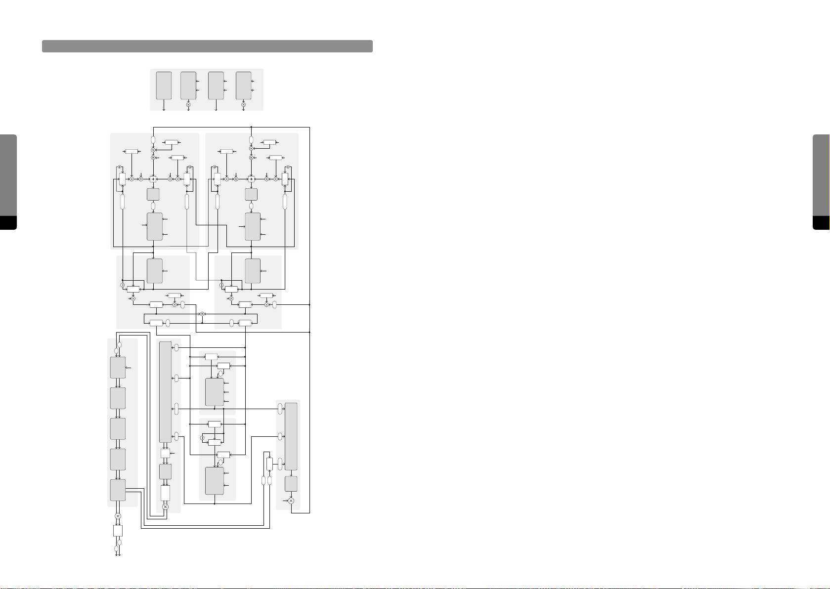
Signal Flow Detailed
Automation and Rendering
Envelope B
Envelope C
Env C
Envelope A
KTVel
KTVel
Gain
Env A
Gate
Gate
KTVel
Gain
Env B
Besides a few exceptions (oscillator phases, unison voices – only eective when playing new notes), all parameters operate as smoothers within the synth engine and can
perform transitions from one value to another in a specified time (adjustable by the user).
This aects modulations, preset transitions and editing of parameters, each having their
individual times.
1
PM FB
Chirp
Oscillator B
Shaper B
Gate
RM
Output Mixer
1
RM
Pan Voice Mix
Shaper
Env C
KT
Env A
Env C
Env A
PM A
Shaper
Shaper A
Env C
FB
B
Comb SVFBA
Key Pos
Filter
Filter
B
Comb
1
Shaper
Shaper B
A
B
Comb
A
B
Variable
State
Env B
PM B
Filter
Note On
Mix
Env A
FB Mix
RM
RM
A
PM PM
Env C KTGate
A
Env C KT
Env B
FB
Env B
PM Self
Filter
PM
Note On
Mix
FB Mix
Gate
Synthesis Engine
1
Shaper
Shaper B
82 83
L
R
CabinetFlanger Echo Reverb
Filter
Gap
FB
1
PM FB
Chirp
PM
Oscillator A
Shaper A
Gate
Dry
1
PM Self
Env C
KT
Env A
Reverb
Wet
Env C
Env A
Shaper
Shaper A
The whole control process of the synth engine is realized by a custom automation protocol, called TCD (time, curve, destination). Anything from a preset recall to performance is
transmitted, even instructions for envelope signals. There will be a separate document in
the future, explaining the basics and capabilities of TCD.
At the moment, adjustable parameters are only capable of handling monophonic values.
It is planned to change this in the future in order to be able to implement splitting, layering of sounds and modulation of selected voices.
5.3 Components of the Synthesis Engine
Env C
FB
Feedback Mixer
EectsSVFComb
Shaper
In this chapter, the individual components are described in further detail. Their functionality is explained and methods for the creation and manipulation of signals are
contemplated. The goal here is to highlight the noticeable and audible eects of certain
mechanisms while avoiding the mathematical and physical foundations if possible. Concludingly, profound knowledge of (digital) signal processing and acoustics is not required
– however, it surely can be helpful.
Envelopes
The primary purpose of the envelopes is to create modulation signals according to
played keys. Their most crucial applications are certainly the amplitudes (peak levels) of
the oscillators, which is predefined. So the amplitude of Oscillator A directly depends on
the signal of Envelope A, as the amplitude of Oscillator B directly depends on the signal
of Envelope B. Besides, there are other targets which can be influenced by the envelopes
according to modulation amount parameters. They are referred to in the following
sections.
Level
Master
Level
KT
Synthesis Engine
So
Clip
L
R
Page 43

In total, there are four envelope signals to be taken use of. Three of them are flexibly
definable, as provided by three parameter groups called Envelope A, B and C. Whereas
Envelopes A and B are applyable in the two branches (Oscillators and Shapers), Envelope C can be used more globally for the modulations of pitches, cuto frequencies,
resonances or feedback levels. In addition, a non-parametric Gate signal is produced and
applied for feedback control and the decay of the Comb Filter.
The Gate signal is a very simple envelope that jumps to 100% intensity when a key
Synthesis Engine
is pressed. When this key is released, the signal drops back to zero within a few
milliseconds.
The signals of the other three envelopes are way more advanced. Lots of parameters
define the behavior of each envelope, including variable sensitivities to the velocities and
pitches of played notes.
84 85
For a particular envelope (A, B or C), there are four consecutive segments defining the signal progression. When a key is pressed, the signal starts by rising from (usually) zero to the
peak level within the Attack time. The peak level can depend on the key-down velocity,
whereas the time can range between zero and 16 seconds and also can depend on the
key-down velocity (shortening it for higher velocities). The Attack curve is linear by default
but can be tweaked to get a concave or convex shape. With a concave shape it starts with
a smaller slope and gets steeper, with a convex shape it is the opposite. The time and
curve of the Attack segment determine the perceived sharpness of the beginning tone.
Regardless of the perceived loudness of the tone up to now, it will disappear by fading
out. Similar to the Attack segment, the Release time can be sensitive to the key-up
velocity.
As explained, the key velocities can influence the perceived loudness of the tone as well
as the speed of its start and demise. In addition, the Key Tracking parameters determine how much the key position influences both the levels and times of the envelope
segments.
In conclusion, an Envelope group can model quite a lot of dierent tonal processes with
varying degrees of realism. It can produce spiky impulses as well as long, complicated
and seemingly artificial contours. All parameters, but especially the timing are highly
precise and their sensitivities to the performing user can be carefully defined as well.
Finally, three more aspects are quite worth mentioning. Whereas the times of the first
two segments (Attack, Decay 1) are well defined by (finite) transitions, the remaining two
segments (Decay 2, Release) approach their destinations exponentially. This means, the
signal takes an asymptotical path towards a specific value, but actually never reaches it.
In order to define the speed of this infinite process by a particular time, the definition is
as following: When the signal drops from 100% towards zero (as described for the Gate
signal), aer the given time the signal will be at approximately 37% still. This relationship
may sound arbitrary or random, but actually reflects countless natural processes (like the
behavior of a plucked string).
Synthesis Engine
When the signal has reached the peak level, a new transition to the Breakpoint level
(between zero and the peak level) will begin. This segment will be active within the given
Decay 1 time (also between zero and 16 seconds). It will impact the early evolution of the
produced tone. The first two segments determine the start transients, which are important for the perceived character of a sound.
When the signal has reached the Breakpoint level, the Decay 2 segment will become
eective. Within a given time, the segment will exponentially approach the Sustain
level (between zero and the peak level as well). The Sustain level defines how much the
perceived tone will persist at a stationary level while holding the corresponding key. High
Sustain levels are typical for pad and organ sounds, for example. If the sustain level is low
or zero, a percussive tone character will emerge, with the Decay 2 time controlling if it
sounds shorter or longer. The sustain level will hold as long as the key remains pressed.
The final segment, called the Release phase will become eective as soon as the corresponding key is released. Within a given time the signal approaches zero exponentially.
Secondly and up to now, all three Envelope groups (A, B, C) have been described at once.
A major dierence of Envelope C as a global modulation source is, that its Breakpoint and
Sustain levels are bipolar. This renders Envelope C more versatile and can make tonal
evolutions even more complex.
At last, another note on the Release segment in the context of the modulation mechanism. All segment times are represented as modulation target parameters, so they can be
influenced by the Macro Controls. And whereas the times of the first three segments can
be precisely tuned between zero and 16 seconds, the Release Time (target) parameter can
be further set to infinite, allowing the Release segment to „freeze“. This allows for the integration of a „Sustain Pedal“, modulating the Release time up to infinity while holding it.
Page 44
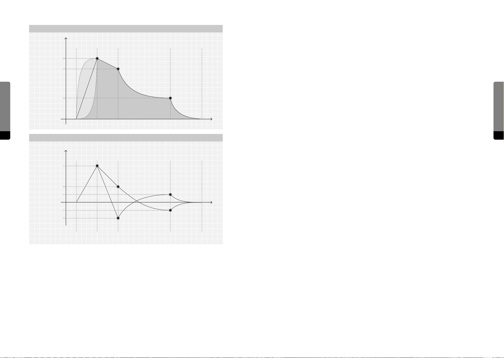
Level
Attack
Envelope A & B
Decay 1 Decay 2 Release
Oscillators
The branches A and B both contain an Oscillator – a source for a sine-wave signal.
Peak Level
Breakpoint Level
The perceived sound of a sine wave is rather simple, as there is just the fundamental,
which is detected by the ear as a pitch. It lacks any further harmonics or partials in general, so the perceived sound is devoid of any timbre.
By phase modulation, wave shaping or ring modulation, new partial tones can be
Synthesis Engine
Sustain Level
created. The resulting waveforms and spectra can vary enormously and evolve over time.
This is the foundation of a sound that later can be further manipulated by the two filters.
When a key is pressed, each oscillator synchronizes to a particular start phase. This
allows both oscillators to run in or out of phase up to the point, where they will cancel
Note On Note O
86 87
Envelope C
Time
each other out. Besides, when using unison, the individual tones can have an individual
phase oset as well. If the start phase of an oscillator is not zero, it will not start at the
zero-crossing of the sine wave. With short Attack times, a clicking will be noticeable, as
sharp transients can occur in that scenario.
Level
Peak Level
Attack
Decay 1 Decay 2 Release
The frequency of an oscillator (the number of oscillations per second) is represented as
a Pitch parameter, providing the familiar format of semitones and cents. The influence
of the position of a pressed key can be weighted by the Key Tracking parameter, adding
Breakpoint Level
Sustain Level
Sustain Level
Breakpoint Level
Time
to the basic tuning of the oscillator. At 100% Key Tracking, the Oscillator pitch directly
corresponds to the keyboard. However, there are other possible influences on the pitch as
a modulation target, typically by the Bender. Envelope C can shi the pitch as well.
By taking use of the Scale group, the pitches of played notes can even be set to dierent
scalings apart from the familiar equidistant temperament of modern western music. If
using unison in addition, a cluster of voices will sound where the Spread parameter can
Note On Note O
stretch the individual pitches apart from one another.
Even each oscillation cycle can vary in frequency, as provided by a Fluctuation parameter.
When Fluctuation is used, each cycle will have a random oset to the basic frequency.
This converts the simple sine-wave to a band-limited noise. At high amounts, the oscillator frequency can randomly vary between 5% and 195% per cycle, which leads to a very
irregular behavior and a wide-band spectrum. The Fluctuation can also be aected by
Envelope C.
Synthesis Engine
In order to manipulate both harmonics and noisiness of the sine wave, phase modulation
(„PM“, oen also referred to as „FM“) can be exploited, as each Oscillator provides several
parameters dedicated to define the complex relations of intermodulations.
Page 45
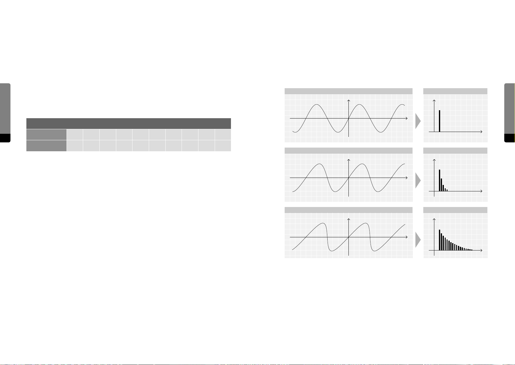
Oscillator PM Self
2
Basically, if a slow „modulator“ signal modulates the phase of another fast and tonal „carrier“ signal, the perceived frequency of the fast signal will change over time, increasing or
decreasing the perceived pitch. The faster the modulator signal becomes, the faster the
frequency of the carrier signal will change. If both signals are periodical, new perceived
frequencies may emerge and others may disappear.
In general, strong and bright spectra can emerge. The produced sounds can be harmonic
and tonal (if the ratios of the Oscillator frequencies can be expressed by fractions of small
Synthesis Engine
integer numbers) as well as noisy and atonal (like a metallic character, emerging from
non-harmonic partials). This strongly depends on relations that both involved oscillators
would have, like their frequency ratios and amounts of phase modulation.
Aer all phase modulation sources were weighted and added, their sum will be fed to
a tunable but static lowpass „Chirp“ filter. This can reduce aliasing eects or chaotic
noisiness, when phase modulation is used excessively.
The bipolar nature of many of the involved parameters further raises the complexity and
lowers the predictability of the system as a whole. The intricate feedback network can be
seen as a textbook definition of a „chaotic system“.
Curve Audio Spectrum
y
dB
Common Frequency Ratios
88 89
Dierence (ST)¹ 0 3.87 4.98 7.02 12 14.04 15.87 19.02 21.69 24
Ratio² 1/1 5/4 4/3 3/2 2/1 9/4 5/2 3/1 7/2 4/1
1 tuning dierence (in semitones) between Oscillator A and B
2 emerging Ratio
More specifically, three modulation sources can be used in parallel for each Oscillator.
12
Curve Audio Spectrum
y
x
Hz
dB
x
Self modulation allows a particular oscillator to feed its own signal back, adding to its
phase. This leads to a saw-like appearance of the oscillator signal and a brighter sound,
depending on the modulation amount. The corresponding parameter is bipolar, aecting
the direction of the saw curve. The corresponding shaper signal can be crossfaded into
the modulation signal, further aecting the spectrum of the resulting oscillator signal. The
corresponding Envelope can also be applied on the amount.
The phase progression of a particular Oscillator can also be aected by the opposite
Curve Audio Spectrum
y
dB
x
Hz
branch (and vice versa). Similar to self modulation, the amount can be set, the branch
shaper signal can be crossfaded and the branch envelope can shape the intensity. This
Hz
allows for complex intermodulations and elevates each Oscillator to function as both a
carrier and a modulator simultaneously.
The third phase modulation source is the global Feedback bus, being defined by the
Feedback Mixer. The amount can be defined and Envelope C can shape the intensity as
well. As the feedback signal can consist of polyphonic and monophonic parts, intermodulations between several (parallel) voices can occur. In most cases, phase modulation by
feedback rapidly leads to noisy behavior.
Synthesis Engine
Page 46
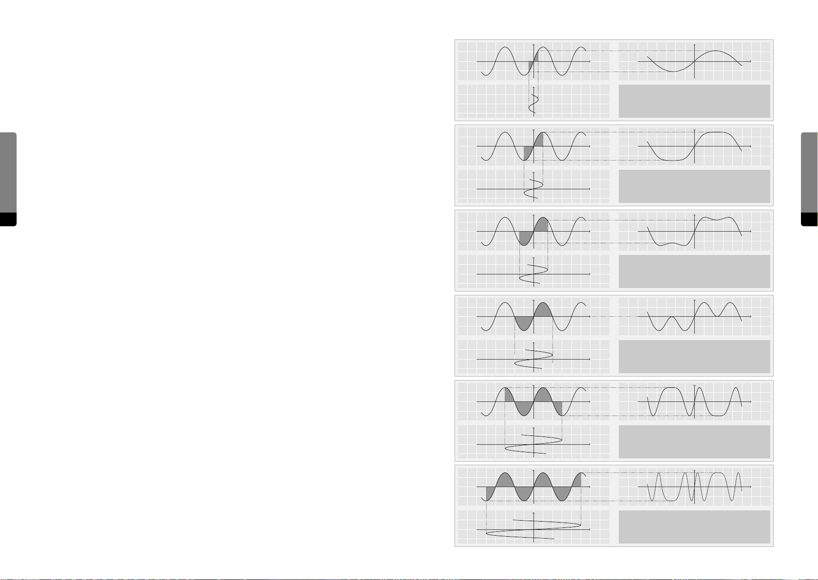
Shapers
y
Output
Each of the two branches is completed by a sine shaper unit, which can further manipu-
x
t
late the oscillator signal and enhance its spectrum. It also allows for the integration of the
global feedback and a ring modulation signal.
The sine shaping mechanism can be compared to the computation of an oscillator signal,
which is derived from a continuously growing phase that is folded over and over again,
Synthesis Engine
thus becoming periodical. From the periodical, wrapped phase signal, a sine approximation can be calculated.
Within a sine shaper, the input signal is first amplified by a Drive parameter, which can
be sensitive to the corresponding branch envelope. Aerwards, it will be interpreted as
a phase signal that will be folded. The resulting signal could be broadly described as the
Input
Input
t
y
x
t
Drive: 0.0 dB
Fold: 100 %
Asymetry: 0 %
Output
t
Drive: 3.0 dB
Fold: 100 %
Asymetry: 0 %
„sine of a sine“.
90 91
Certain overtones will emerge in proportion to the Drive level. The folding characteristic
can be blended from a so clipping behavior by a Fold parameter. With no fold present,
y
x
Output
t
the shaper eect resembles more a distortion or saturation eect, producing dierent
harmonics.
Furthermore, an Asymetry parameter can shi the fundamental frequency by one octave.
The resulting shaped signal can be crossfaded with the input signal by a bipolar Mix
amount (as previously mentioned, the bipolar nature of lots of signal components can
raise the complexity when using phase modulations or feedback).
Two more signals can be blended into the mix. The feedback signal can be fed into a
branch, the amount can be sensitive to Envelope C (blendable with the Gate signal).
With the application of feedback, the global Feedback loop will be closed to some extent
Input
Input
t
y
x
t
Drive: 6.0 dB
Fold: 100 %
Asymetry: 0 %
Output
t
Drive: 9.0 dB
Fold: 100 %
Asymetry: 0 %
(depending on further settings).
Finally, the two branch signals are multiplied and each branch can blend to the „Ring
Modulation“ signal by a certain amount. Ring modulation produces interesting patterns in
y
x
Output
t
the resulting spectrum, depending on the two incoming signals. Symmetrical frequency
components emerge (one with the dierence of the incoming frequencies, one with the
sum of the incoming frequencies).
Input
t
Drive: 12 .3 dB
Fold: 100 %
Asymetry: 0 %
Synthesis Engine
Concludingly, the Shaper is another versatile module providing dierent ways to manipulate an Oscillator signal. Distortion eects are as possible as sine shaping, and feedback
and ring modulation can be applied. The shaper not only aects the signal of a branch,
but can also be blended onto phase modulation sources for the oscillators.
Input
y
x
t
Drive: 16 .8 dB
Fold: 100 %
Asymetry: 0 %
Output
t
Page 47
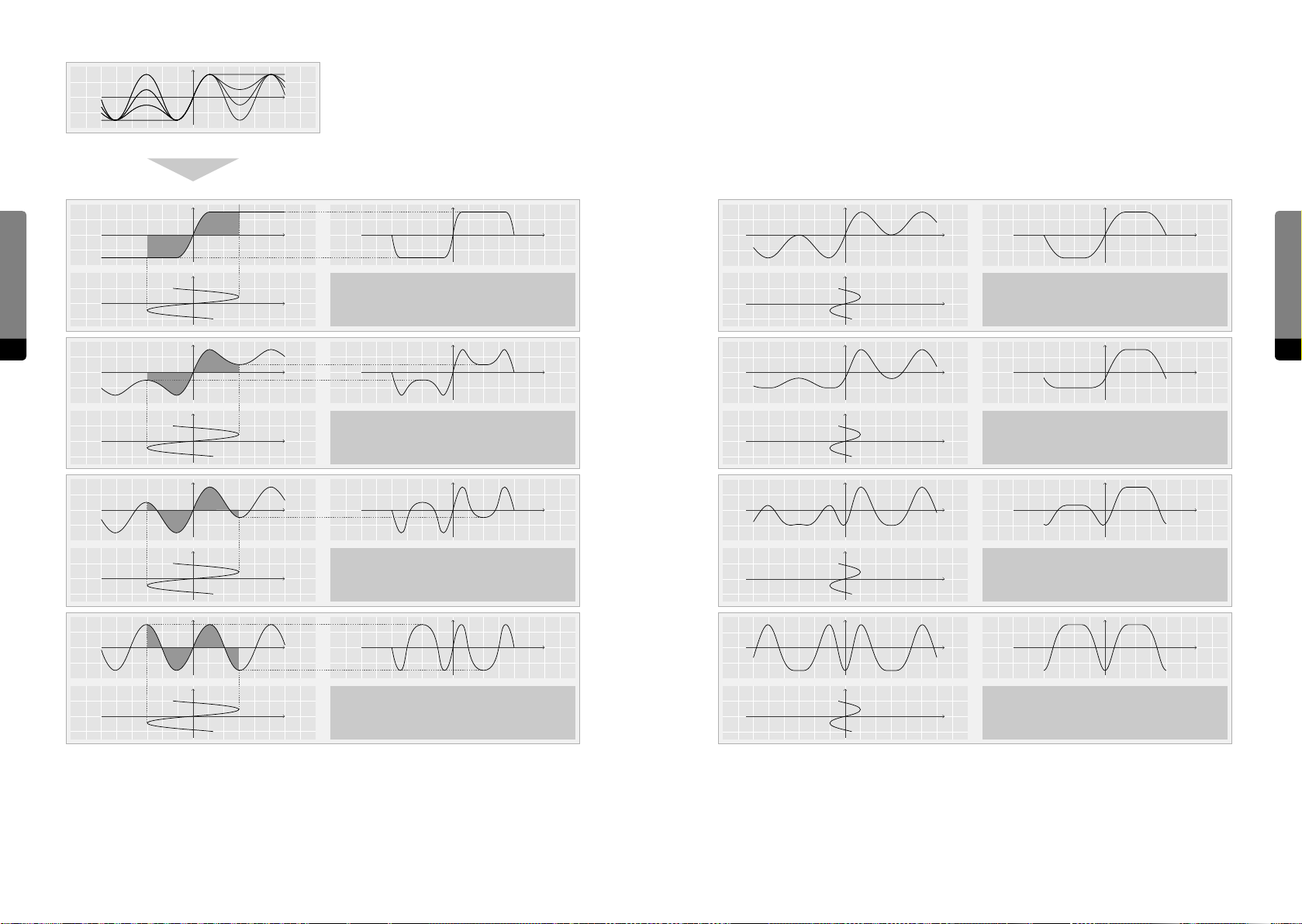
Shaper: Asymetry
5
Shaper: Fold
4
y
x
y
Synthesis Engine
x
Input
92 93
Input
Input
t
y
t
y
t
y
x
x
Drive: 12.0 dB
Fold: 0 %
Asymetry: 0 %
Drive: 12.0 dB
Fold: 33 %
Asymetry: 0 %
Drive: 12.0 dB
Fold: 66 %
Asymetry: 0 %
Output
t
Output
t
Output
t
Output
y
x
t
y
x
t
y
x
t
y
Drive: 3.4 dB
Fold: 50 %
Asymetry: 0 %
Drive: 3.4 dB
Fold: 50 %
Asymetry: 20 %
Drive: 3.4 dB
Fold: 50 %
Asymetry: 60 %
t
t
t
Synthesis Engine
Input
x
t
Drive: 12.0 dB
Fold: 100 %
Asymetry: 0 %
t
t
x
Drive: 3.4 dB
Fold: 50 %
Asymetry: 100 %
t
Page 48
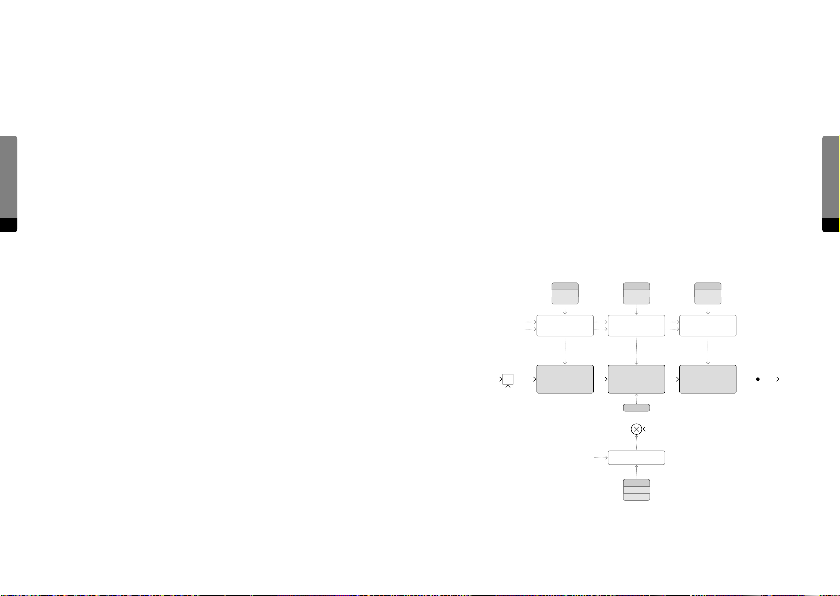
Comb Filter
The branch signals (A, B) are provided as sources for two dierent filter units, the first of
which is the „Comb Filter“. It is an accurately tunable delay with a versatile local feedback
loop, fed by an adjustable crossfade mix of both branch signals.
The term „Comb“ describes the eect of a signal being combined with a delayed version
of itself, leading to phase interferences (which can be constructive or destructive, mainly
Synthesis Engine
94 95
depending on the delay time). Certain harmonics of the input signal can be amplified or
canceled, so the spectrum is aected.
Furthermore, the term „tunable“ refers to the relationship between the delay time of
signal repetitions and a perceived tonal frequency, which emerges when the delay time is
suiciently small (smaller times produce higher frequencies, as usual). The „Pitch“ parameter of the Comb Filter can be sensitive to Key Tracking and the influence of Envelope C.
The delayed signal is passed to the local feedback branch, which includes two filter
components. At first, a two pole allpass filter is applied, which has a tunable frequency
The amount of feedback determines how long it takes for the feedback to disappear
aer the input signal has faded out. This exponential process is referred to as the „Decay
Time“, which can be sensitive to Key Tracking (modeling a tendency some musical instruments possess, like strings tend to dampen faster with higher notes).
The Decay parameter is bipolar, as negative feedback amounts can cancel every second
repetition, eectively tuning the signal down by one octave. The signal of the Gate envelope can also be applied to the local feedback loop, reducing the amount to a certain
degree when a key is released (so the Comb Filter feedback only remains for sustained
notes).
The delay time can additionally be modulated by a crossfade mix of both branches, determined by a „Phase Modulation“ parameter (as mentioned, in certain scenarios, delay
times and phases can closely relate).
So in a general sense, the Comb Filter can act as a tunable, delay based resonator that
can strongly alter the spectrum of the incoming signal due to its integrated allpass filter.
which can be sensitive to Key Tracking and the influence of Envelope C and a resonance.
Allpass filters do not aect the amplitudes of certain frequency components (as highor lowpass filters do), but they will aect the phases of these components, which are
comparable to individual delay times. Below the (center) frequency, the phase shi is
Pitch AP Tune Hi Cut
Key Trk
Env C
Key Trk
Env C
Key Trk
Env C
minimal (zero), rising to 180 degrees at the frequency and then to 360 degrees above the
frequency. The Resonance parameter defines the slope of that shi. This mechanism has
a profound eect on the signal spectrum, as it can both create and destroy harmonic
Note Pitch & Pitchbend
Env C
Delay Time
Control
Center Frequency
Control
Cuto
Control
signal components.
Synthesis Engine
The allpass filter is followed by a lowpass filter, damping higher frequency components
according to a tunable pitch parameter which can be sensitive to Key Tracking and the
influence of Envelope C. The damping eect is closely related to acoustic processes (as
substances like air have this property). It also aects the persistence of the local feedback.
Delay 2-Pole Allpass 1-Pole Lowpass OutIn
Note On/O
AP Reson
Feedback Control
Decay
Key Trk
Gate
Page 49
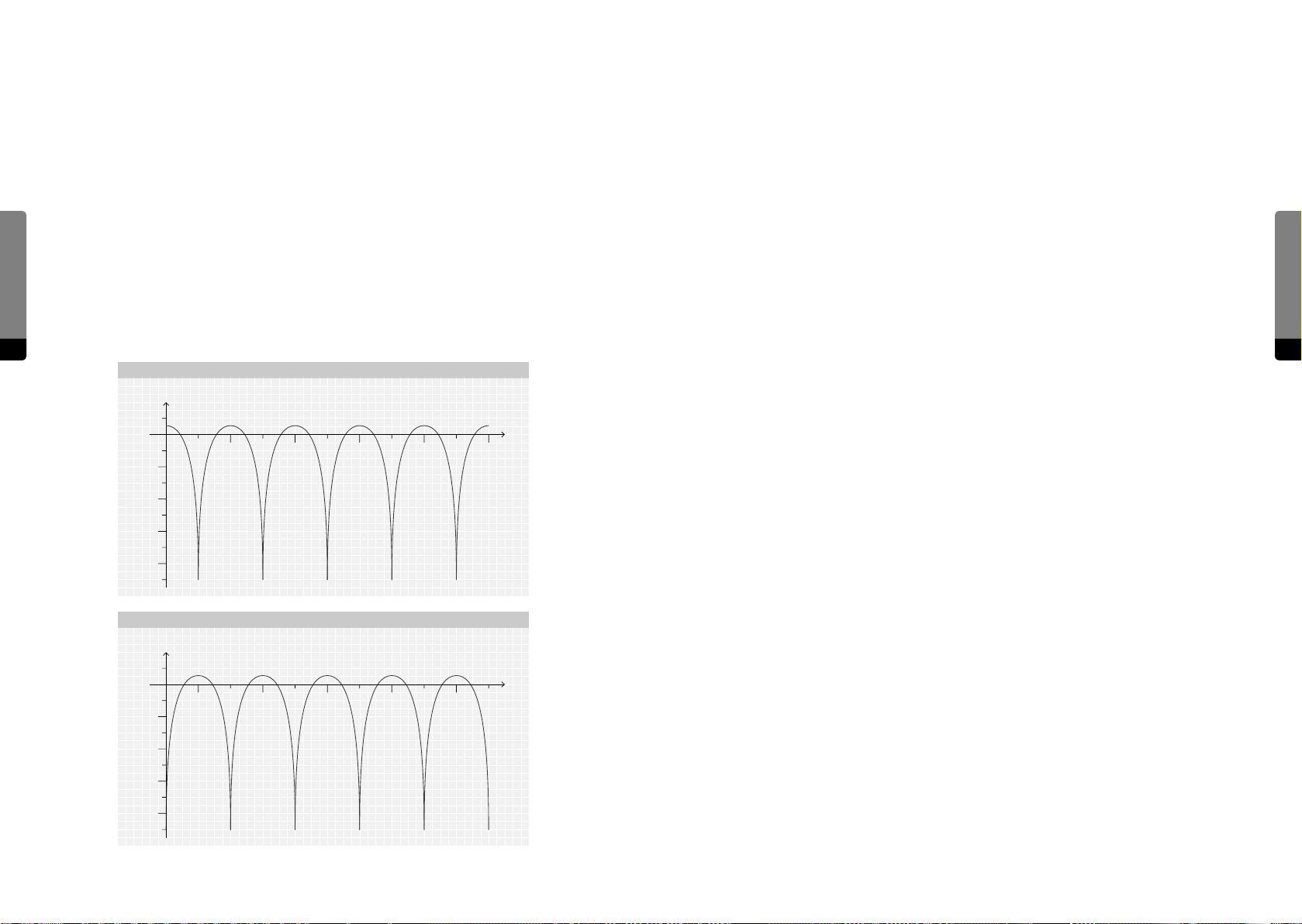
The following diagram shows a simplified frequency response for the Comb Filter.
Comb Filter – Frequency Response
7
Consider a tonal signal (with a clear fundamental frequency) which feeds the Comb Filter.
The Comb Filter output is added to the signal (upper graph) or subtracted from the signal
(lower graph).
Both graphs show the typical, generalized frequency response of a comb eect, as shown
by the periodical peaks. The width of the peaks depends on the Comb Filter’s pitch
parameter (equivalent to a delay time), meaning that certain signal frequency compo-
Synthesis Engine
nents will be attenuated and other components will be amplified, depending on the delay
time.
In addition, when subtracting the Comb Filter signal from the incoming signal, the peaks
are shied, and the emerging comb tone will be lowered by one octave.
State Variable Filter
The second applyable filter to the branches is called the „State Variable Filter“, a tool for
multifunctional subtractive filtering that is fed by an adjustable crossfade mix of both
branch signals. The Comb Filter can be faded into the input mix as well.
The State Variable Filter consists of two two-pole filters with blendable characteristics
(lowpass, bandpass, highpass) which can operate in parallel or in series by a continuously
adjustable amount. In serial mode, the damping slope can be raised from 12 to 24 dB per
octave (becoming a four-pole filter eectively). In parallel applications, the filters can also
be used to create two formants (useful for vowel-like sounds).
The filter frequencies are determined by a tunable center frequency which can be sensitive to Key Tracking and the influence of Envelope C. A Spread parameter determines how
much the individual filter frequencies are shied apart from the center frequency. With no
96 97
Magnitude
(dB)
0 dB
– 20 dB
– 40 dB
1.0 2.0 3.0 4.0 5.0
Non-inverted Mix
Frequency
Ratio
spreading, one peak emerges at the center frequency. The strength of the peak depends
on the filter resonance, which also can be sensitive to Key Tracking and the influence of
Envelope C. When spreading is applied, the peak splits into two peaks, weakening strong
resonances and creating formants.
The filter type can be continuously blended between an overall lowpass, bandpass and
highpass behavior. In serial mode with a negative spreading, a band-rejecting (notch)
behavior can be achieved as well.
A crossfade mix of both branches can also be applied for frequency modulation.
– 60 dB
– 80 dB
Parallel behavior can be produced in two ways, by either adding or subtracting the
second filter to/from the first. Subtraction will lead to phase cancellations.
Synthesis Engine
Magnitude
(dB)
0 dB
– 20 dB
– 40 dB
– 60 dB
– 80 dB
Inverted Mix
0.5 1.5 2.5 3.5 4.5
Frequency
Ratio
In conclusion, the State Variable Filter is a versatile subtractive filter capable of creating
formants and dierent characteristics.
Page 50
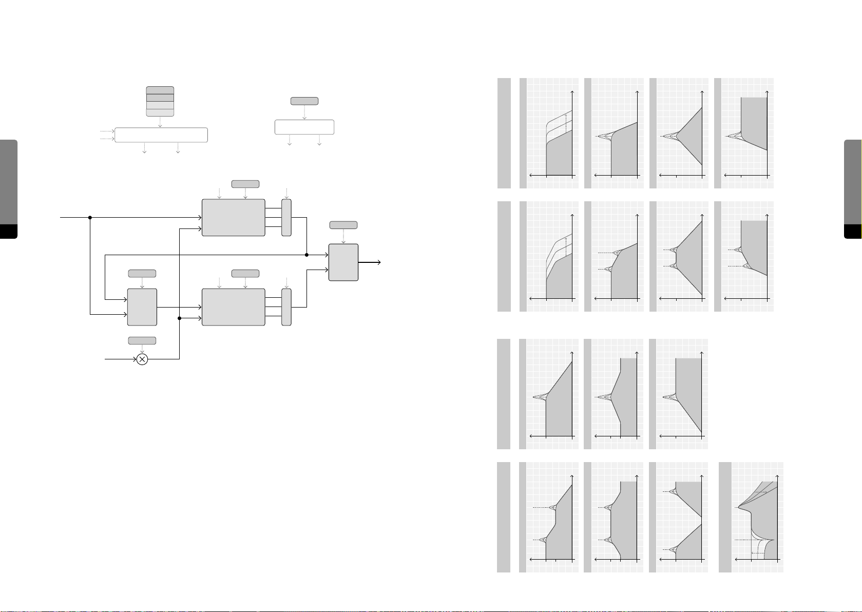
Note Pitch & Pitchbend
L-B-H = 50 %, Spread > 0 st, Reson = var.
– 6 dB
– 6 dB
Parallel < 0 (var.), L-B-H = 0 %, Spread > 0 st
L-B-H = 0 %, Spread > 0 st, Reson = var.
L-B-H = 50 %, Spread < 0 st, Reson = var.
L-B-H = 0 %, Reson = 0…100 %
L-B-H = 100 %, Reson = 0…100 %
L-B-H = 0 %, Reson = 0 %, Cuto = var.
Parallel = 0 %, Spread > 0 st
L-B-H = 50 %, Reson = 0…100 %
Synthesis Engine
Env C
Cuto
Spread
Key Trk
Env C
Cuto Control
Cut 1 Cut 2
L–B–H
L-B-H Control
L-B-H 1 L-B-H 2
State Variable Filter, Filter Response:
Parallel = 0 %, Spread = 0 st
L-B-H = 0 %, Reson = 0 %, Cuto = var.
L-B-H = 0 %, Reson = 0…100 %
24 dB/oct
L-B-H = 50 %, Reson = 0…100 %
12 dB/oct
24 dB/oct
L-B-H = 100 %, Reson = 0…100 %
Cut 1
Reson
In
98 99
Parallel
FM
Cut 2
2-Pole SVF
Reson
L-B-H 1
L-B-H 2
Parallel
X-Fade
Out
2-Pole SVFX-Fade
Gain
0 dB
Gain
0 dB
Gain
Frequency Frequency
24 dB/oct
12 dB/oct
Gain
0 dB 0 dB
Gain
0 dB
Frequency Frequency
12 dB/oct
Gain
0 dB
Gain
0 dB
Frequency Frequency
Gain
Frequency Frequency
12 dB/oct
24 dB/oct
0 dB
FM
FM
from A-B
Frequency
12 dB/oct
L-B-H = 0 %, Reson = var.
Gain
0 dB
12 dB/oct
L-B-H = 50 %, Reson = var.
Gain
0 dB
– 6 dB
L-B-H = 100 %, Reson = var.
12 dB/oct
Gain
0 dB
Synthesis Engine
Frequency Frequency
12 dB/oct
Parallel = 100 %, Spread ≠ 0 st Parallel = 100 %, Spread = 0 st
12 dB/oct
Gain
0 dB
Gain
Frequency
0 dB
Gain
Frequency Frequency
12 dB/oct12 dB/oct
0 dB
Gain
Frequency
0 dB
Page 51
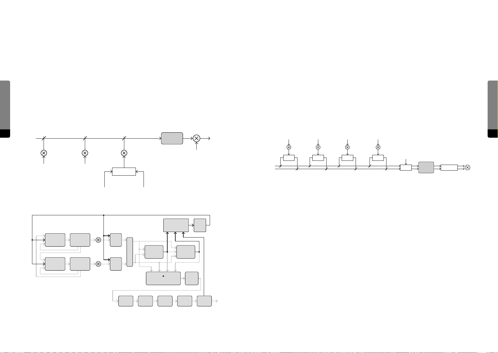
Output Mixer
12
Feedback Mixer
Level
Feedback Mixer
11
Output Mixer
The global feedback signal, usable for phase modulation and within the Shapers,
is defined by a mix of four signals provided by the two filters and the Eects section
(blendable between pre and post Reverb). Each signal is weighted by a bipolar Amount
parameter, as the polarity can have a noticeable influence on the feedback behavior.
A sine shaper (providing Drive, Fold and Asymetry, as described for the branch Shapers)
Synthesis Engine
can manipulate the sum signal and create additional harmonics. The sum also can be
amplified or damped by a Level parameter that can be sensitive to Key Tracking.
The feedback signal will be a mixture of polyphonic signals (provided by the filters) and
monophonic signals (provided by the eects, having no more voice association and being
a downmix of the original stereo signal).
100 101
Comb SVF Eects
Reverb
Dry Wet
Shaper
KT
The (main) output signal, being passed to the Eects section, is defined by a stereo
mix of four signals provided by the two branches (A, B) and the two filters (Comb, SVF).
Each signal can be weighted by a bipolar amount and positioned in the stereo field by a
panning parameter.
A sine shaper (providing Drive, Fold and Asymetry, as described for the branch shapers)
can manipulate the sum signal and create additional harmonics. The sum also can be
amplified or damped by a Level parameter. The key position of a note can also be applied
for the tone’s position in the stereo field by a „Key Pan“ parameter.
Aer the output mixer, the signal will be monophonic (the sum of all voices) and at the
same time dual channel (with stereo spreading).
A B
Pan
Pan
Comb SVF
Pan Pan
Key Pos
Pan Voice Mix
Shaper
Level
Eects
Feedback Path:
A chain of five stereo eects can be applied to the output signal, each eect having its
own characteristics and an individual mix amount, which blends it into the output mix.
Synthesis Engine
Oscillator A Shaper A
Oscillator B Shaper B
Feedback Mixer Shaper
FB Mix
State
Variable
Filter
RM
FB Mix
Flanger Echo Reverb
Comb
Filter
Output Mixer (Stereo )
Cabinet
Gap
Filter
Shaper
Flanger
The first eect is a dynamic stereo delay capable of producing chorus-, phaser- or flangerlike sounds. Its basic mechanism can be compared to the Comb Filter, although the
Flanger is not sensitive to Key Tracking. The usual sweeping eect arises when the delay
time is changing (due to modulations), as the delayed signal is combined with the input
signal and changing harmonics are created.
As the delay times are relatively short, this eect is not able to create wide spatial eects,
but a certain perception of depth will emerge nevertheless. The delay time can be spread
for both channels with a „Stereo“ parameter.
Page 52
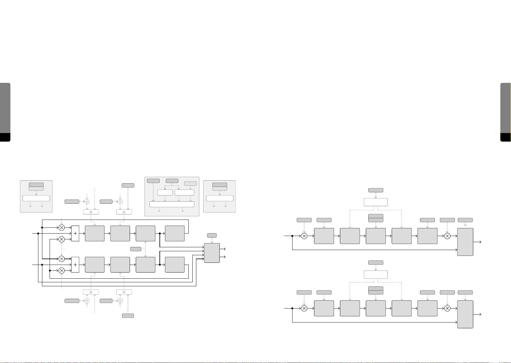
The local delay feedback bus consists of two filters, the first of which is an allpass filter
with a tunable frequency, aecting the phases of the signal’s frequency components. The
second filter is a one-pole lowpass filter with tunable frequency, damping the feedback
signal. The feedback level can be determined by an amount parameter and as this is a
stereo eect, cross feedback can be applied as well, feeding some amount of a signal
from one channel to the other (and vice versa).
Modulation sources for the Flanger are provided by a stereo LFO (with adjustable Rate
Synthesis Engine
and stereo Phase oset) and a simple (monophonic) envelope signal (immediately
jumping to the velocity when a key is pressed and then exponentially approaching zero
within a time corresponding to the Rate parameter). A crossfade of the two sources
can be applied as modulation for the delay time and for the allpass filter frequency
independantly.
102 103
Finally, the Flanger signal can be blended into the mix by a bipolar Mix parameter, as the
signal polarity can have a strong eect when using the global feedback signal.
Cabinet
The second eect is called „Cabinet“, providing the possibility to further shape the
signal in terms of saturation, overdrive and distortion. It can be regarded as a basic amp
simulator.
A sine shaper (providing Drive, Fold and Asymetry, as described for the branch Shapers) is
the central element of this eect, allowing for the creation of new harmonics to the signal.
Before and aer the actual shaping, filtering is applied in order to further manipulate the
distortion eect. The signal passes through a highpass filter with adjustable frequency
(cutting low signal components) before being fed into the shaper. Aer the shaping, a
lowpass filter with adjustable frequency determines the amount of high signal components (boosted by the distortion).
A Tilt parameter has a further influence on the signal spectrum before and aer the
shaping, as it can emphasize either low or high signal components that will be aected by
the shaper.
The shaped signal can be amplified by a separate „Cab Level“ parameter, before being
crossfaded with the input signal by the Mix parameter.
Synthesis Engine
1-Pole
Lowpass
1-Pole
Lowpass
Env Rate
X-Fade
Mod L Mod R
Highpass
Highpass
Stereo Cross FB
Time Control
Time L Time R
In L
In R
Time Mod AP Mod
FB Self
FB X
FB Self
Time Mod AP Mod
Time L
Delay
Delay
Time R
Mod LMod L
4-Pole
Allpass
4-Pole
Allpass
Mod RMod R
AP Tune
Hi Cut
AP Tune
Phase
LFOEnv
50 Hz
50 Hz
FeedbackTime
Feedback Control
FB Self FB X
Mix
X-Fade
Out L
Out R
In L
In R
Tilt
Tilt Control
Drive Lo Cut Hi Cut Cab Lvl Mix
2-Pole
Highpass
Drive Lo Cut Hi Cut Cab Lvl Mix
2-Pole
Highpass
Pre Post
Shelving
Filter
Pre Post
Shelving
Filter
Fold
Asym
Shaper
Tilt
Tilt Control
Fold
Asym
Shaper
Shelving
Filter
Shelving
Filter
4-Pole
Lowpass
4-Pole
Lowpass
X-Fade
X-Fade
Out L
Out R
Page 53
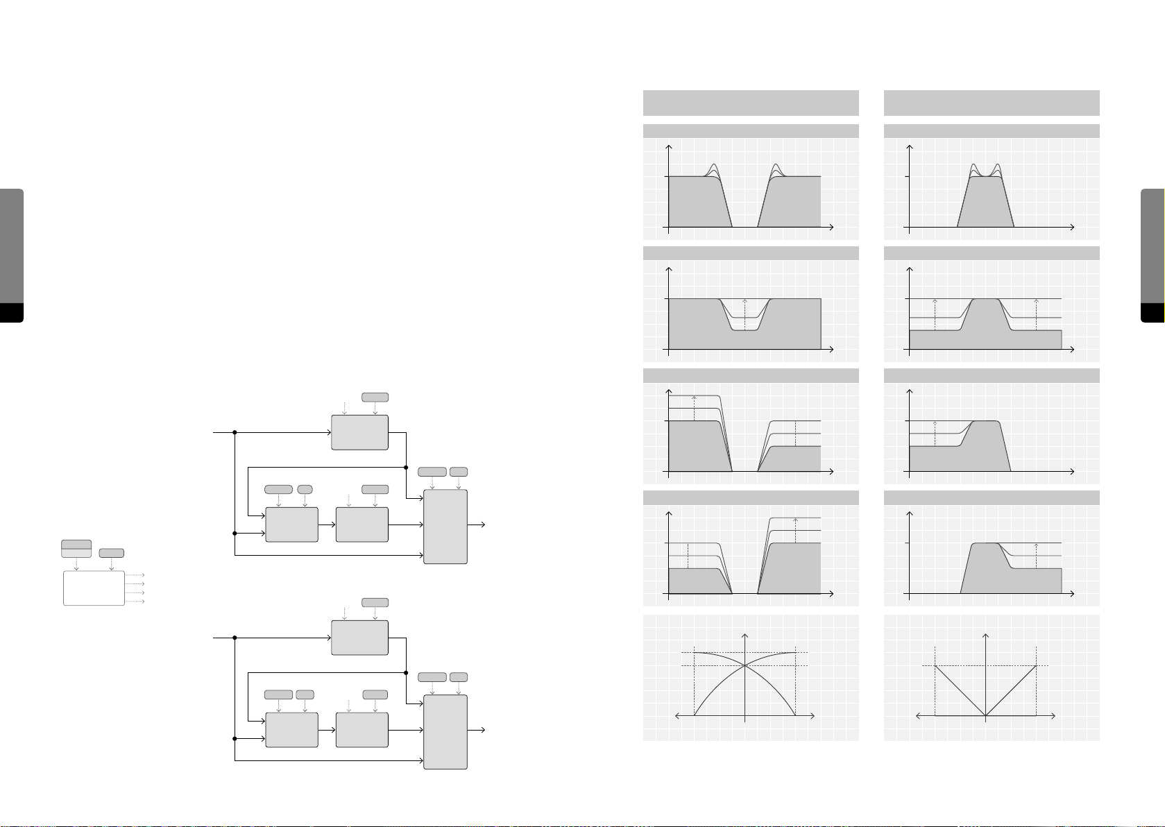
Gap Filter
Gap Filter, Filter Response
The Gap Filter marks the third eect and provides further filtering of the signal. It consists
of two four-pole filters (with a damping slope of 24 dB per octave) which can run in
parallel or in series. The filter types are static, as the first filter is a highpass, followed by
the second (lowpass) filter.
The filter frequencies can be determined by a „Center“ frequency, which can be spread in
Synthesis Engine
the stereo field and shied by the „Gap“ parameter, creating an oset between the high-
Gain
0 dB 0 dB
Parallel/Band Reject (Mix > 0) Serial/Band Pass (Mix < 0)
Balance = 0, Mix = 1, Reson = var. Balance = 0, Mix = –1, Reson = var.
Gain
and lowpass filters. The filter resonance can be adjusted as well, creating two resonance
peaks in the signal spectrum.
Both filter outputs can be blended by a Balance parameter, defining a crossfade mix of
the two components.
104 105
The bipolar Mix parameter determines the amount of filtering in the resulting signal,
crossfading the input signal with the filtered signal. Positive mix values mean that the
Balance = 0, Reson = 0.5, Mix = 0 ... 1
Gain
0 dB
Frequency Frequency
Balance = 0, Reson = 0.5, Mix = –1 ... 0
Gain
0 dB
filter components run in parallel, resulting in a band-reject behavior. Negative values
produce a bandpass eect, as the filter components are running in series.
Lo Cut L
Reson
Hi Cut L
Lo Cut R
4-Pole
Highpass
4-Pole
Lowpass
Balance Mix
Reson
Reson
Center
Stereo
Cuto
Control
In L
Balance Mix
X-Fade
Gap
Lo Cut L
Lo Cut R
Hi Cut L
Hi Cut R
X-Fade
Out L
Mix = 1, Balance = 0 ... –1
Gain
0 dB
Mix = 1, Balance = 0 ... 1
Gain
0 dB
Frequency Frequency
Mix = –1, Balance = 0 ... –1
Gain
0 dB
Frequency Frequency
Mix = –1, Balance = 0 ... 1
Gain
0 dB
Frequency Frequency
Synthesis Engine
In R
X-Fade
4-Pole
Highpass
Hi Cut R
4-Pole
Lowpass
Gain Gain
1.41
Balance Mix
ResonBalance Mix
X-Fade
Out R
A_lo A_hi
–1 –1 11
1.001.00
Balance Balance
A_lo A_hi
Page 54
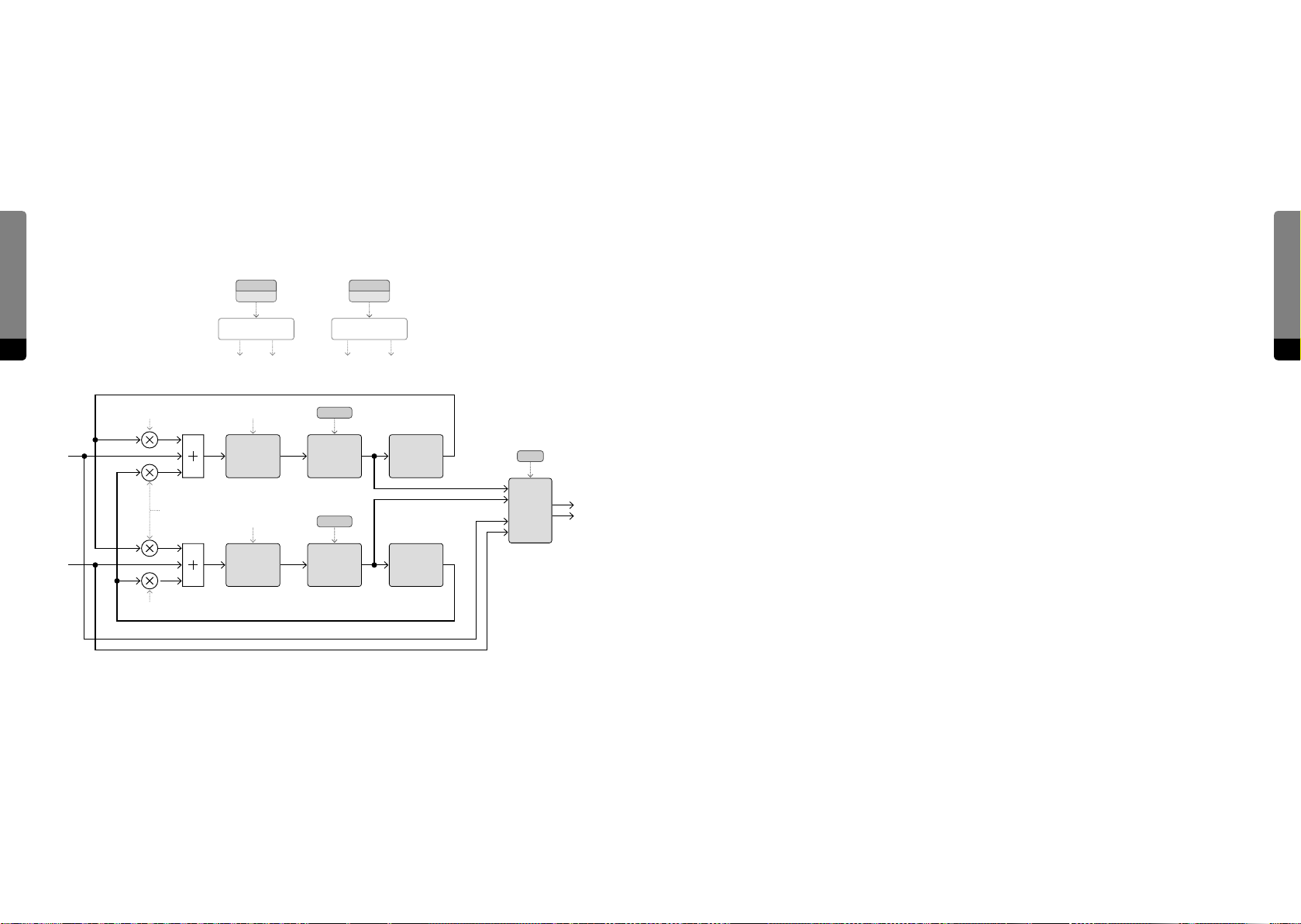
Echo
Reverb
The fourth eect is a stereo delay, providing a spatial eect of repeating echoes. The delay
time can be adjusted and spreaded between the le and right channel. Within the local
feedback, a tunable lowpass filter allows for damping, and the feedback level can be
defined by an amount and a cross-feedback (feeding one channel back to the other and
vice versa). The echo can be blended into the mix by an adjustable amount parameter.
Synthesis Engine
Finally, the signal is passed to the Reverb unit, providing another spatial eect in terms of
hall, room or reverberation.
The Size parameter determines how long it takes for a signal to fade out, which has a profound impact on the perceived room size. A Pre Delay parameter can also have a strong
influence in the size perception.
The local feedback behavior is determined by a Color parameter, aecting its brightness
and a Chorus parameter which can lead to a less static feedback behavior.
Time Feedback
Stereo Cross FB
Time Control Feedback Control
106 107
Time L Time R FB Self FB X
The Reverb signal can be blended into the mix by a separate amount parameter.
Post Processing
The resulting signal (a mixture of the Output Mix and the Eects section) can be amplified or attenuated by a Master Level parameter, before it passes through a so clipper,
preventing the signal from being clipped at the D/A converter.
Other Parameter Groups
Besides the Master Level, the Master group also contains a Master Tune parameter which
can shi the whole tuning of the instrument by up to 48 semitones in both directions.
The Scale group allows for redefining the scale of the instrument, which is the equal temperament by default. The Base Key of a scale can be defined and all remaining 11 keys
In L
In R
FB Self
FB X
Time L
Delay
Time R
Delay
Hi Cut
1-Pole
Lowpass
Hi Cut
1-Pole
Lowpass
50 Hz
Highpass
50 Hz
Highpass
Mix
X-Fade
Out L
Out R
can have an individual oset (up to 800.0 cents - eight semitones – in both directions) to
FB Self
the equal temperament. So a variety of dierent scales is achievable, including historical
and traditional settings, pentatonic scalings or exotic and experimental types.
Synthesis Engine
The Unison group provides additional control and allows for unison voices (more than
one sounding voice per pressed key). The number of unison voices can be adjusted (one
by default). Three spread parameters can determine, how each unison voice is spread
against the others: Detune can spread the pitches, Phase can spread the oscillator start
phases and Pan can spread the panning of individual unison voices.
Page 55

5.4 Using Hardware Sources
General Aspects
The eight Hardware Sources of the C15 can be seen as special controllers, which are
designed for live performance. While playing a certain sound, the Hardware Sources can
be used for modulations, changing the sound character.
Synthesis Engine
108 109
Four dierent types of Hardware Sources are provided, each type having its individual
aspects (four Pedals, two Ribbons, one Bender, one Aertouch). As for the (external) Pedals, their aspects strongly depend on the type of Pedal that is used. The following section
contemplates all relevant aspects of Hardware Sources and external controllers in general.
Continuity
Controllers can essentially behave in two dierent manners. There are switches (like a
„Sustain Pedal“) and there are continuous controllers (like a „Volume Pedal“). Although
continuous behavior may be preferred in most use cases and can be seen as a general
recommendation, switches can also be used when integrating external Pedals (providing
only two states: on and o). All four integrated Hardware Sources are continuous.
Continuous controllers, on the other hand, can be unipolar (the usual case, providing one
direction of possible movement: up or down) or bipolar (like a „Pitch Bender“, providing
two directions of movement: up and down).
Directionality and Polarity
Controllers with a switch behavior can behave in two dierent manners as well. There
are opener switches (like a „Sustain Pedal“) and there are closer switches (like a „Mute
Pedal“ or „Damping Pedal“). The dierence between these two types is the direction they
are taking: opener switches go from minimum to maximum, closer switches operate in
a reversed manner. Commonly (but misleadingly) this is referred to as „Pedal Polarity“.
However, regardless of the direction of a controller, it can be integrated and directions
can be manipulated by modulation amounts.
Return Behavior
Some controllers (like a „Sustain Pedal“ or a „Pitch Bender“) return to a certain position
aer using them (usually, the position would be zero or the center), whereas other controllers may remain at their position aer releasing them. Controllers that are returning
to their center position usually are bipolar (and the center position equals zero in this
case). The return behavior aects the type of modulation amount of the corresponding
Hardware Source, which can be either continuous (for a returning Hardware Source) or
switch-like (for non-returning Hardware Sources, providing only „on“ and „o“).
Integration and Recall Behavior
Dierent Hardware Sources can behave dierently when a new preset is recalled. When
a preset is recalled while using Hardware Sources, a well-defined behavior is not guaranteed for now (as it is still in development), so we recommend to leave the Hardware
Sources untouched when loading a new preset.
In addition, only the two integrated Ribbons can successfully load their states in a preset
recall, if they are in Non-Return mode. Returning Hardware Sources can lead to the
described eects, if they are not in their return position when a preset is loaded.
On the other hand, the (external) Pedals can not be aected by loading new presets. So,
they could be at a position that is not expected and produce a jumping behavior when
used. A so takeover option is planned to be implemented in the future and for now, we
recommend to set the (non-returning) Pedals to their zero position before saving and
loading presets. This way, the behavior of the C15 will be well-defined and predictable
throughout.
Additional Settings
There are more settings provided for each Hardware Source in the Setup menu, depending on the type of source. The Bender and Aertouch provide a curve, weighting the
movements, whereas the Ribbons provide a „Relative Factor“, amplifying movements on
the Ribbons when using relative mode.
Synthesis Engine
Operation Modes
Except for the Ribbons, all Hardware Sources operate in absolute mode. Ribbons on
the other hand, can operate in both absolute and relative mode (the relative mode can
amplify drag gestures on the Ribbon).
Page 56
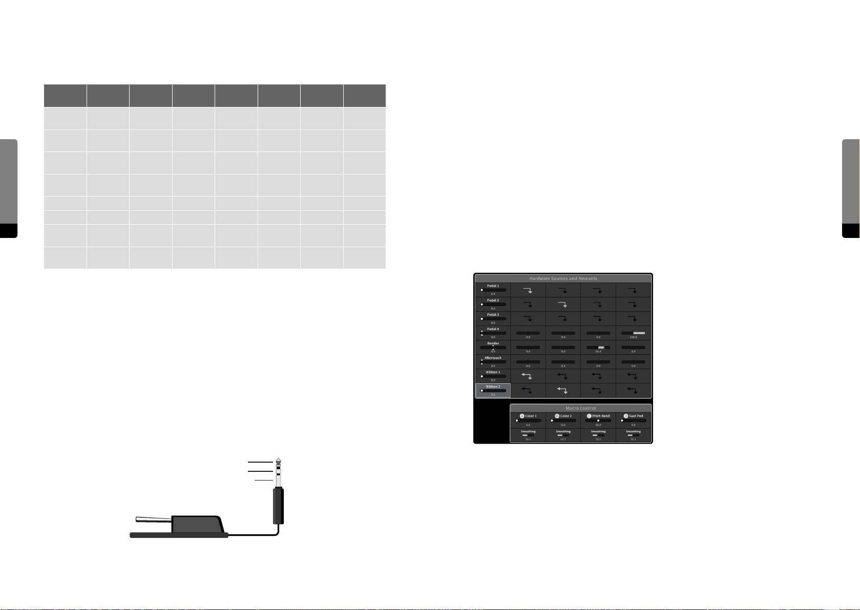
Functionality Overview
All the mentioned dierent aspects of Hardware Sources are shown in the following table:
Modulation Aspects
As already mentioned, the modulation amount of a certain Hardware Source on a Macro
Control depends on the source’s Return Behavior (only returning sources allow for a
Source Continuity Polarity
Pedal 1
Synthesis Engine
110 111
Pedal 2
Pedal 3
Pedal 4
Bender continuous bipolar center integrated n/a Curve absolute
Aertouch continuous unipolar zero integrated n/a Curve absolute
Ribbon 1 continuous
Ribbon 1 continuous
continuous /
switch
continuous /
switch
continuous /
switch
continuous /
switch
unipolar /
bipolar
unipolar /
bipolar
unipolar /
bipolar
unipolar /
bipolar
unipolar /
bipolar
unipolar /
bipolar
Return
Behavior
non / zero /
center
non / zero /
center
non / zero /
center
non / zero /
center
non / center integrated yes
non / center integrated yes
Integration
external no
external no
external no
external no
Recall
Behavior
Settings
Pin
Assignment
Pin
Assignment
Pin
Assignment
Pin
Assignment
Relative
Factor
Relative
Factor
Operation
Mode
absolute
absolute
absolute
absolute
absolute /
relative
absolute /
relative
continuous amount).
Furthermore, when a non-returning Ribbon is assigned to a Macro Control, the assignment will be bidirectional. In other words, the Ribbon will move the Macro Control and
vice versa.
Considering the Hardware Sources, their current settings and the modulation amounts
on Macro Controls alltogether, they can be referred to as a „Modulation Template“. All
included settings will be stored and recalled with presets, but for dierent use cases (like
dierent Pedals on another device), the template may not work properly. We plan to
further investigate on template functionalities (like import and export functions) and may
oer solutions in the near future.
For the sound design (and included factory presets) so far, the following template
appeared to be meaningful, and it can be found in most of the presets:
Pedal Integration
For now, the safe and recommended method of integrating external Pedals is to turn the
device o beforehand. Aer all Pedals are plugged in the provided sockets, the C15 can
be switched on again. The booting process will recognize the Pedals’ circuit architectures
and integrate them accordingly.
Synthesis Engine
There is a Setup menu provided as well, in which the pin assignment of each Pedal can be
set manually. However, this menu should only be used if the pin assignment of a Pedal is
known, as wrong assignments can easily lead to overheating, possibly causing permanent
damage on the device. Besides, the menu is still in development and proper functionality
is not guaranteed for now.
Tip
Ring
Sleeve
The template defines two non-returning, continuous Pedals (1 and 2) for Macro Controls
A and B, which are used to modulate dierent sound aspects like phase modulation
intensities, filter frequencies, resonances or eect amounts, for example. Similarly, the
two Ribbons are mapped on the two Macro Controls as well.
In addition, Macro Control C is assigned to the Bender and primarily used for bending
pitches. The remaining Macro Control D is assigned to a returning, continuous Pedal (4),
which serves as a Sustain or Damper Pedal (depending on the sound).
Page 57
Setup
6. Setup (C15 System Settings)
The C15 also features a few global settings that are preset-independant. They are
organized in the Setup menu and mainly define the interaction with peripherals (such
as sensitivities for velocities, external Pedal integration or connected devices via Wi-Fi).
Besides, the Setup menu allows for installing updates and transferring backups.
Chapter 4.12 Setup Navigation provides all information on accessing and navigating the
Setup menu both on the Panel Unit and on the Graphical User Interface. The following
passages explain all provided menu items.
Device Settings [Panel Unit, Graphical UI]
Preset Glitch Suppression
This option can be enabled in order to avoid drastical changing pitches and other
emerging artifacts, being provoked by a preset change. The suppression will be realized
by clearing (flushing) all delay buers when a new preset is loaded.
߰ Note that this feature is not fully implemented yet, as the suppression is not perfect in
every case and can still produce small artifacts, depending on the preset change’s circumstances. But in general, the eect is quite noticeable.
GUI Settings [Graphical UI only]
A complete reference to the settings of the Graphical User Interface can be found in
chapter 4.15 Graphical UI Functionality.
Setup
112 113
Edit Smoothing Time
When editing a parameter, the new adjusted value will be approached within the Edit
Smoothing Time, which can range between zero and 200 ms. Higher times will lead to a
slower response of the sound engine. This time does not aect preset recalls or modulations (having their own, individual times).
Velocity Curve
The Velocity Curve determines the sensitivity of the instrument for key velocities. A so
setting increases the sensitivity for low velocities, a hard setting increases the sensitivity
for high velocities. With the normal setting, the sensitivity remains equal for all velocities.
Aertouch Curve
The Aertouch Curve determines the sensitivity of the instrument for Aertouch gestures. A so setting increases the sensitivity for low Aertouch intensities, a hard setting
increases the sensitivity for high Aertouch intensities. With the normal setting, the
sensitivity remains equal throughout.
Bender Curve
The Bender Curve determines the sensitivity of the instrument for Bender gestures. A so
setting increases the sensitivity for low bending intensities, a hard setting increases the
sensitivity for high bending intensities. With the normal setting, the sensitivity remains
equal throughout.
Pedal Settings
As described in chapter 5.4 Using Hardware Sources, the integration of external Pedals
can be done manually. For each Pedal, the circuit type can be chosen. Nevertheless, we
recommend to connect Pedals only when the instrument is switched o, in order to avoid
a wrong and possibly harmful integration.
Hardware UI [Panel Unit only]
Encoder Acceleration
The Encoder in the Edit Panel can detect acceleration gestures and apply them to an item
in focus accordingly. With suicient acceleration, even high resolution parameters can be
completely traversed with only one or a few turns of the encoder.
Ribbon Relative Factor
Similarly, drag gestures on the two Ribbon touchstrips can be amplified by the Ribbon
Relative Factor. This option is only eective, when a Ribbon is in relative mode.
Signal Flow Indication
As described in chapter 4.8 Overviews, the Flow Overview allows for a fast and easy
impression on how signals of a preset are routed. However, blinking LEDs may distract the
user in some cases, therefore the Flow Overview is optional.
System Info [Panel Unit, Graphical UI]
Device Name
The Device Name of the C15 instrument can be chosen by the user. It will appear in the
meta data of presets and determine the SSID of the Wi-Fi network. In order to complete
the renaming process, restart the instrument aerwards.
SSID
During the booting process, the SSID will be generated according to the Device Name. A
Wi-Fi network with the SSID should be available aer booting. Besides the Device Name,
the SSID contains a static prefix („NL-C15-“). When establishing a Wi-Fi connection, choose
the network with the corresponding SSID.
Page 58
Setup
Passphrase
The secured Wi-Fi connection has to be confirmed by a passphrase. This passphrase can
be seen and changed in the System Info (eective aer rebooting). Note that the passphrase cannot be chosen, it will be randomly generated.
Free Internal Memory
The remaining free disk space is displayed in order to see, if the instrument is capable of
holding more presets.
Soware Version
For developers, the versions of integrated components is displayed as well.
7. Updating the C15
߱ The included USB stick of the C15 package has a special format – other USB
sticks will not work for C15 updates.
New soware versions will be made available as downloads on the Nonlinear Labs website. For an update of your C15 please follow the protocol below step by step:
114
Date / Time
The instrument contains its own system clock, which will be included in preset meta data
in the form of timestamps. It can be adjusted as well.
Update Available
The final menu entry is an indicator for an available update, if a USB stick containing that
update was plugged in. This can be used to test, if the update file is valid before actually
updating (see Notes on Soware Updates).
About [Hardware UI, Graphical UI]
In the About section, the Nonlinear Labs developer team is listed.
Backup
USB Available (Panel Unit only)
In order to backup all banks or restore a preexisting backup, a USB stick has to be plugged
in. The “USB Available” indicator shows if a USB stick is currently present.
Save and Restore
In order to save or restore all current present banks to or from a backup file, enter one of
these options. The backup file will be transferred to or from a present USB stick (if using
the Panel Unit) or it will be downloaded on your browser (if using a mobile device and
entering one of the provided context menus). The process may take some time, depending on the number of involved presets or banks.
߰ Details on how to save or restore backups on the Hardware User Interface and the Graphi-
cal User Interface can be found in chapter 4.13 Backups.
1. Select the desired update in the download area of the Nonlinear Labs website:
www.nonlinear-labs.de/download/download.html
and download it to your computer.
2. Connect the USB stick which is included in the C15 package to your computer.
3. The downloaded file is a .tar archive file named “nonlinear-c15-update.tar”. Please do
not extract it. Instead just copy or move it to the top directory of the USB stick..
4. Switch o the C15 and plug the USB stick to the USB connector on the backside of the
Base Unit. Then start the C15.
5. An automatic update process will start, as indicated on the Base Unit Display. When
the shown status indicates that the update has finished, switch o the C15.
6. The USB stick can be removed now. Aer a successful installation, the update file on
the USB stick will have been renamed to „nonlinear-c15-update.tar-copied“. It should
be deleted before the next update.
When starting the C15 again, it will run the new soware version.
Besides, the C15 can display if a valid update file is found on the USB stick, which will be
useful prior to installing updates. This can be seen in the System Info section of the Setup
Menu, as there is an „Update Available“ entry at the bottom.
We recommend to always have the latest version installed, but it is also possible to downgrade to a previous version by running the described installation process with the .tar file
for that version. However, preset compatibility is only guaranteed if updating to newer
versions. Presets created with a newer version may be corrupted when loading them with
an older version.
Updating the C15
115
Page 59

8. Specifications
Parameter Editing
Phase 22 Synthesis Engine
• 2 Oscillators (sine wave, phase modulation, frequency randomization)
• 2 Shapers (sine curve, adjustable foldback and asymetry)
• Ring Modulator
• Comb Filter (tunable, with allpass and lowpass)
Specifications
116 117
• State Variable Filter (multi-mode, 2-4 poles, FM)
• Feedback Mixer (4 input signals, shaper for the sum)
• Feedback bus with 4 destinations
• Output Mixer (stereo, 4 input signals, shaper for the sum)
• 5 Stereo Eects: Phaser/Flanger/Chorus, Cabinet (amp simulation),
8-pole Gap/Band Filter, Echo, Reverb
• 3 ADBDSR Envelopes, adjustable attack curve
• Velocity sensitivities for envelope levels, attack times, and release times
• 4 Macro Controls, assignable to up to 86 target parameters
• 8 Hardware Sources, mappable to the 4 Macro Controls
• Number of parameters: 328
• Resolution of the parameters: typically 1000 steps (250 ... 15000 steps)
• Resolution of key velocity, ribbons, bender, aertouch, pedals: 4000 steps
• 20-voice polyphony, variable Unison settings
• Scale parameters for micro-tuning the 12 steps of the octave
• 4 Selection panels, each with 24 buttons and LEDs
• Labeling by exchangeable magnetic overlays
• Edit panel with an OLED display (256 x 64 dots), incremental encoder and 18 buttons
• The ribbons are also assignable for parameter editing.
• User-definable Init preset and Default values
• Randomize function
• Graphical User Interface on any WiFi-enabled device running a browser,
unique zoom-and-pan navigation, enabled for touch
Preset System
• User-definable banks
• Unlimited number of presets per bank
• User-editable infos per preset
• Search function to find presets by name or tags in the infos
• Morphing transition between presets.
Undo System
• Unlimited undo for all user interactions, including sound editing steps
• Undo list with support for dierent editing branches (tree view)
Connectors
Hardware Features
• 61-key (5 octave) Fatar keybed with semi-weighted long-arm keys
• Note-on and note-o velocity sensitivity
• Monophonic aertouch
• Two 800 mm touch strips (ribbons), each with 33 LED dots
• Ribbon modes: absolute, relative, combinable with return-to-center
• Lever (magnetic force loaded) for pitchbending and similar applications
• Control panel with an OLED display (128 x 32 dots) and four buttons
• Output volume potentiometer (at the front)
• Headphone level potentiometer (at the front)
• The Base Unit can be used without the Panel Unit
• Magnetic front panel foils replaceable to support future synthesis engines
• Main audio outputs (L, R) (TRS, balanced by transformers)
• Headphone output at the front (TRS)
• 4 inputs for analog controls, such as pedals (TRS, flexible pin-assignment)
• USB host connector for data exchange and soware updates
Dimensions
• Base Unit only: 900 x 290 x 100 mm (width x depth x height)
• Including Panel Unit: 900 x 410 x 160 mm (width x depth x height)
Weight
• Base unit: 10.5 kg
• Panel Unit: 3 kg
Specifications
Page 60
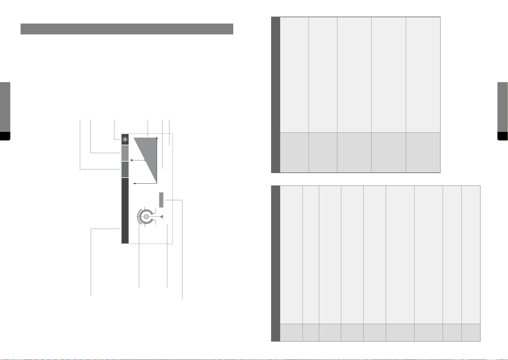
9. Parameter Reference
Parameter Reference
Scaling Types
Parameter Unit (see table below)
Modulation Unit
If a parameter is a modulation target for
Active Indicator
This symbol indicates if a parameter is
influencing the signal flow of the synth, as
Macro Controls, the unit of the modulation
amount will be indicated.
indicated by its LED.
118 119
Value Graph, min to max
Scaling Type, see table below
Resolution, coarse (fine)
Most parameters have a continuous, linear scaling type.
This type is suitable when the displayed value is directly
proportional to the control position and precision remains
constant for the whole value range.
Envelope times and the Comb Filter Decay time have an
exponential scaling type, covering a wide value range with
decreasing precision. The displayed value doesn’t rise by a
constant value, but rather by a factor (20 per quarter).
Some parameters (eect times for example) have a
parabolic scaling type instead of being linear. The displayed
value is proportional to the square of the control position
in this case. The resulting behaviour of the parameter feels
more realistic as if it would use linear scaling.
The Mixer and Main Output levels come with a parabolic
gain scaling type and show their value in decibels (dB). At
minimum, they will mute the signal, at the center position,
they will not aect the signal at all and at maximum, they
will amplify the signal by 12 dB (~400%).
Non-continuous parameters with discrete values (such as
Unison Voices and Scale Base Key) come with the integer
scaling type. This is suitable for suiciently low value ranges
and results in a switch-like behaviour. The fine mode is not
eective in this case.
Parameter Reference
Legend to signs and symbols
Parameter Name
The background color indicates if a parameter
is directly selectable on the Hardware User
% %
Parameter
Interface, being on top of the corresponding
parameter stack (dark grey), or if the selection
of this parameter takes more than one push of
a button (light grey).
50.0
Modulation Indicator
75.025.0
A modulation segment is shown, if a
parameter can be modulated.
linear
inf
100.0
0.0
100 (1000) steps
50.0
Factory Default Value
“inf” Indicator
For some parameters at the lower or upper end
of their range the value will get infinite and will
be replaced by “-inf” or “inf”.
linear
exponential
parabolic
parabolic (gain)
integer
Unit Reference
Amount-like parameters oen use a normalized value range in percent
(%), spanning from zero (or -100, when the parameter is bipolar) to 100
percent.msTime-relevant parameters indicate their values in milliseconds (ms),
meaning that 1000 ms equal one second.stPitch-relevant parameters indicate their values in semitones (st). The
interval of one semitone corresponds to two consecutive keys (at
default key tracking). 12 semitones equal one octave.ctThe Scale Oset parameters are also pitch-relevant, but show their
values in cents (ct), oering more precision. 100 cents correspond to one
semitone.
Gain-relevant parameters show their values in decibel (dB), the common
format of representing signal levels. Zero decibel correspond to 100 %
signal, and a dierence of 6 dB approaches a doubling of the signal.
Attack and Release Velocity parameters come with a custom time-re-
lated format in decibel (dB_T). A full velocity will decrease the
corresponding Envelope segment time by the indicated value in dB (6
dB approaching 50 % of the given time).
Envelope Level Key Track parameters come with a custom gain-related
format in decibel per semitone (dB/st). The corresponding gain will
change according to the played key by the given amount of decibel per
semitone.HzThe Flanger Rate parameter indicates its values in Hertz (Hz), the
number of oscillations per second.
Phase-related parameters indicate their values in degrees (deg), mean-
ing that 360 degrees correspond to a full circle.
%
dB
dB_T
dB/st
deg
Page 61
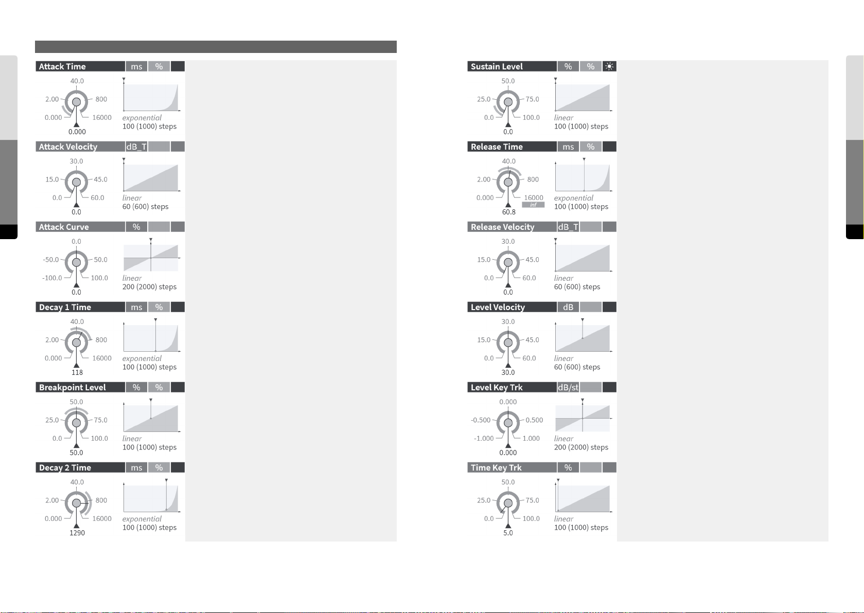
Envelope A
Envelope A
Parameter Reference
120 121
Time of the (polynomial) Attack segment in milliseconds.
Velocity influence on the Attack time. The value represents
the logarithmic amount of the reduction of the Attack time
by high Note-On velocities.
Curvature of the (polynomial) Attack segment.
(negative: decelerating slope, zero: linear, positive: accelerating slope)
Time of the first (linear) Decay segment in milliseconds.
Sustain level (target of the second Decay segment).
Time of the (exponential) Release segment in milliseconds
(infinite at maximum).
Velocity influence on the Release time. The value represents
the logarithmic amount of the reduction of the Release time
by high Note-O velocities.
Influence of the key velocity on the peak, breakpoint and
sustain levels of the envelope [maximum dynamic range in
dB].
Envelope A
Parameter Reference
Level of the Breakpoint between the two Decay segments.
Time of the second (exponential) Decay segment in milliseconds.
Key tracking of the envelope’s peak, breakpoint and sustain
levels [dB per semitone].
Positive values: higher levels for higher notes (+1.0 = +12 dB
per octave).
Negative values: lower levels for higher notes (-1.0 = -12 dB
per octave). Origin at C3 = 60 semitones.
Key tracking of the attack, decay and release times. The
value determines how much shorter the times get for higher
notes.
Page 62
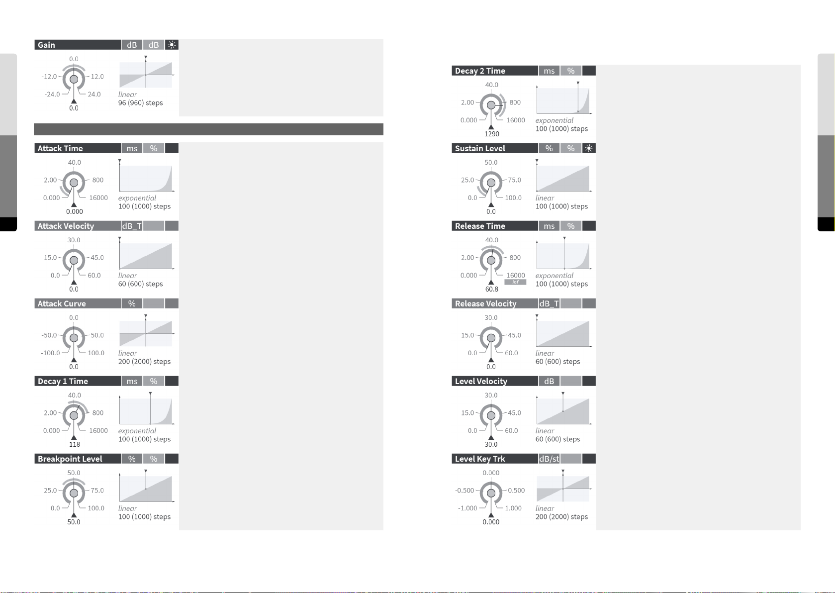
Envelope B
Gain [in dB] of the envelope signal. As this signal modulates
the Oscillator and Shaper A, the Gain influences the level and
the amount of phase modulation and distortion.
Time of the second (exponential) Decay segment in milliseconds.
Envelope B
Parameter Reference
122 123
Envelope B
Time of the (polynomial) Attack segment in milliseconds.
Velocity influence on the Attack time. The value represents
the logarithmic amount of the reduction of the Attack time
by high Note-On velocities.
Curvature of the (polynomial) Attack segment.
(negative: decelerating slope, zero: linear, positive: accelerating slope)
Time of the first (linear) Decay segment in milliseconds.
Sustain level (target of the second Decay segment).
Time of the (exponential) Release segment in milliseconds
(infinite at maximum).
Velocity influence on the Release time. The value represents
the logarithmic amount of the reduction of the Release time
by high Note-O velocities.
Influence of the key velocity on the peak, breakpoint and
sustain levels of the envelope [maximum dynamic range in
dB].
Parameter Reference
Level of the Breakpoint between the two Decay segments.
Key tracking of the envelope’s peak, breakpoint and sustain
levels [dB per semitone].
Positive values: higher levels for higher notes (+1.0 = +12 dB
per octave). Negative values: lower levels for higher notes
(-1.0 = -12 dB per octave).
Origin at C3 = 60 semitones.
Page 63
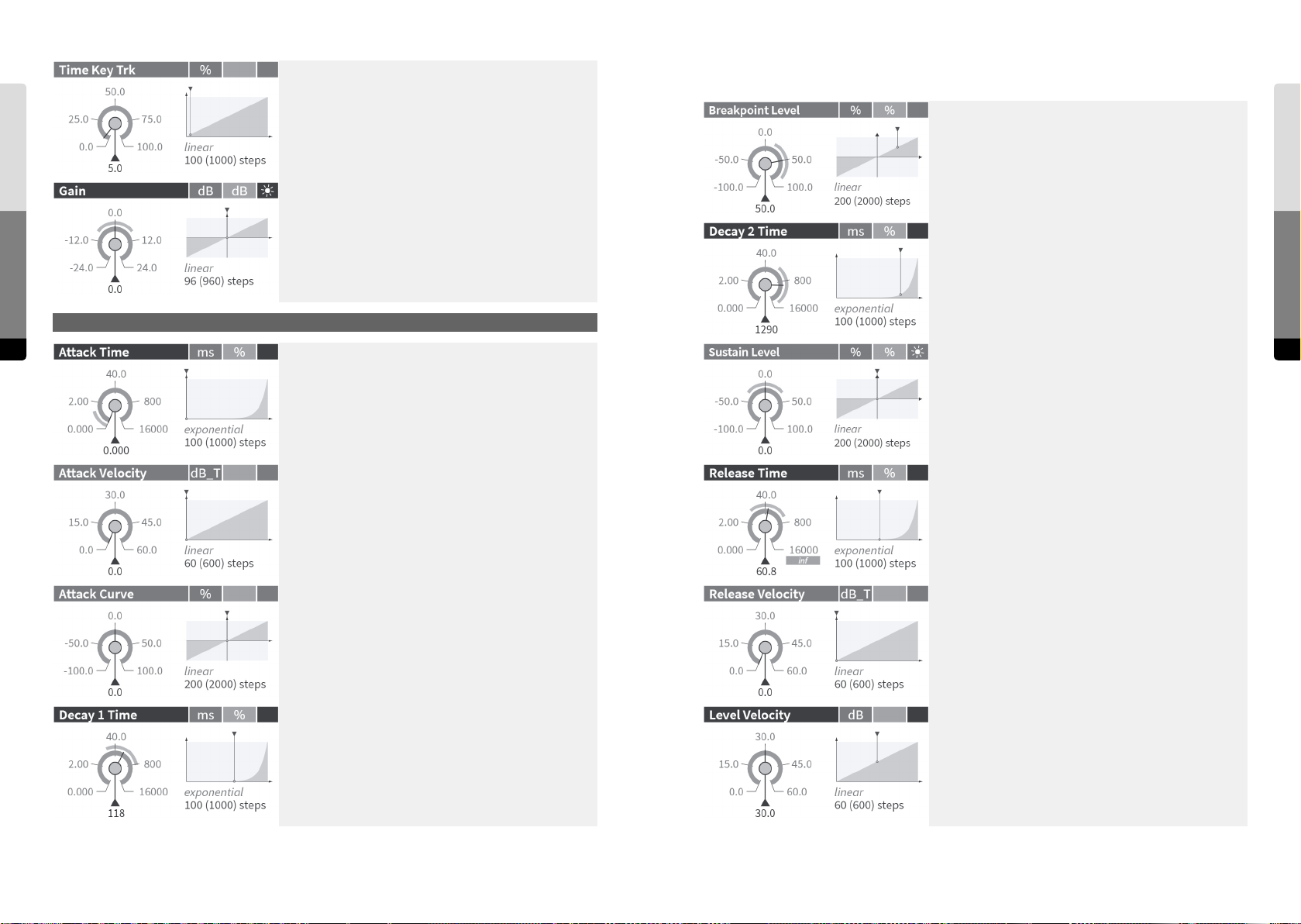
Envelope C
Parameter Reference
Key tracking of the attack, decay and release times. The
value determines how much shorter the times get for higher
notes.
Gain [in dB] of the envelope signal. As this signal modulates
the Oscillator and Shaper B, the Gain influences the level
and the amount of phase modulation and distortion.
Level of the Breakpoint between the two Decay segments.
Envelope C
Time of the second (exponential) Decay segment in milliseconds.
Envelope C
124 125
Time of the (polynomial) Attack segment in milliseconds.
Velocity influence on the Attack time. The value represents
the logarithmic amount of the reduction of the Attack time
by high Note-On velocities.
Curvature of the (polynomial) Attack segment.
(negative: decelerating slope, zero: linear, positive: accelerating slope)
Time of the first (linear) Decay segment in milliseconds.
Sustain level (target of the second Decay segment).
Time of the (exponential) Release segment in milliseconds
(infinite at maximum).
Velocity influence on the Release time. The value represents
the logarithmic amount of the reduction of the Release time
by high Note-O velocities.
Influence of the key velocity on the peak, breakpoint and
sustain levels of the envelope [maximum dynamic range in
dB].
Parameter Reference
Page 64
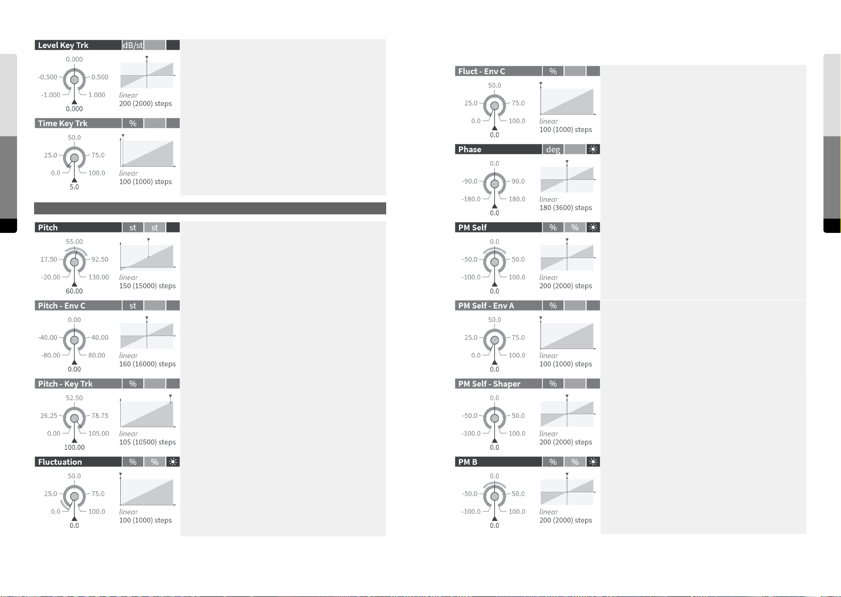
Oscillator A
Parameter Reference
Key tracking of the envelope’s peak, breakpoint and sustain
levels [dB per semitone].
Positive values: higher levels for higher notes (+1.0 = +12 dB
per octave).
Negative values: lower levels for higher notes (-1.0 = -12 dB
per octave).
Origin at C3 = 60 semitones.
Key tracking of the attack, decay and release times. The
value determines how much shorter the times get for higher
notes.
Amount of modulation of the frequency fluctuation by
Envelope C. At zero, the modulation stays constant, at higher
values, the envelope applies a time-variant attenuation.
Oscillator A
Start phase [in degrees]. The Oscillator will be set to this
phase position with each Note-On.
Oscillator A
126 127
Pitch (logarithmic frequency) of Oscillator A at C3 (MIDI note
60) [in semitones, based on MIDI note numbers].
The range below zero is shaped in the way that -20 corresponds to 0 Hz.
Amount of pitch modulation by Envelope C [in semitones].
Key tracking of the oscillator pitch. It’s the scaling factor
between the key position (relative to C3 = 60 semitones) and
the pitch of the oscillator. At 100.0 %, the pitch follows the
equal-tempered scale. At values slightly larger than 100.0 %,
the tuning will be stretched. At 50.0 %, a quartertone scale
emerges and at 0.0 %, the pitch is constant for all keys.
Fluctuation of the oscillator frequency.
If the parameter is set larger than 0.0 %, the frequency is
changed at the beginning of each oscillation period by
a random amount. At 100.0 %, the maximum frequency
variation is +/- 95 %.
Amount of phase modulation by Oscillator & Shaper A (local
feedback).
Envelope (A) amount for the phase modulation by Oscillator
& Shaper A (local feedback).
At zero, the modulation stays constant, at higher values, the
envelope applies a time-variant attenuation.
Mix amount of Shaper A in the signal being used for phase
modulation (self). At zero, the output signal of Oscillator
A is used. At negative values, the signal from the Shaper is
inverted.
Amount of phase modulation by Oscillator & Shaper B (cross
feedback).
Parameter Reference
Page 65
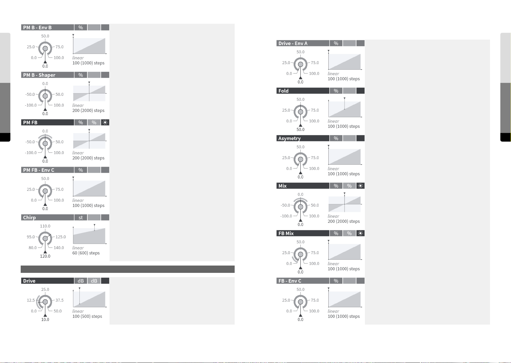
Envelope (B) amount for the phase modulation by Oscillator
& Shaper B (cross feedback).
Shaper A
Parameter Reference
At zero, the modulation stays constant, at higher values, the
envelope applies a time-variant attenuation.
Mix amount of Shaper B in the signal being used for phase
modulation (B -> A). At zero, the output signal of Oscillator
B is used. At negative values, the signal from the Shaper is
inverted.
Amount of phase modulation by the Feedback signal.
128 129
Envelope (C) amount for the phase modulation by the
Feedback signal.
At zero, the modulation stays constant, at higher values, the
envelope applies a time-variant attenuation.
Envelope (A) amount for the Drive factor.
At zero, the gain stays constant, at higher values, the envelope applies a time-variant attenuation.
Amount of folding back of the shaper curve for high input
amplitudes.
0.0 %: flat saturation, no folding
100 %: fully folded back (periodic sine curve)
A higher amount of folding leads to a soer but more nasal
sound.
Asymetry of the shaper curve, generating even (2nd, 4th, ...)
harmonics. At higher values it becomes a parabolic curve
that shis the frequency of the fundamental to its double.
Mix amount of Shaper A in the signal sent to the Filters
and to the Output Mixer. At zero, it is the input signal of the
Shaper - behind FB Mix. At negative values, the signal from
the Shaper is inverted.
Shaper A
Parameter Reference
Cuto [in semitones] of the lowpass in the phase modulation
signal path that can be applied to reduce the level and
frequency of “chirping” appearing at higher amounts of self
modulation, cross-feedback through the other oscillator, or
global feedback.
Shaper A
Input gain [in dB] of the sine shaper stage. Higher gains will
create more distortion and harmonics.
Crossfades between Oscillator & Shaper A (at zero) and the
Feedback signal for the signal A.
Envelope (C) amount for the Feedback Mix. At zero, only a
Gate signal is applied, at higher values, Envelope C is faded
in.
Page 66
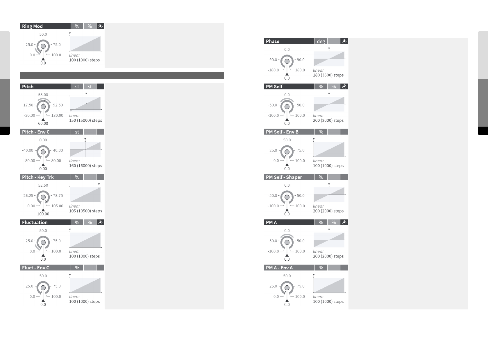
Oscillator B
Mix amount of the ring modulation between both Oscillators
& Shapers.
Start phase [in degrees]. The Oscillator will be set to this
phase position with each Note-On.
Oscillator B
Parameter Reference
130 131
Oscillator B
Pitch (logarithmic frequency) of Oscillator B at C3 (MIDI note
60) [in semitones, based on MIDI note numbers].
The range below zero is shaped in the way that -20 corresponds to 0 Hz.
Amount of pitch modulation by Envelope C [in semitones].
Key tracking of the oscillator pitch. It’s the scaling factor
between the key position (relative to C3 = 60 semitones) and
the pitch of the oscillator. At 100.0 %, the pitch follows the
equal-tempered scale. At values slightly larger than 100.0 %,
the tuning will be stretched. At 50.0 %, a quartertone scale
emerges and at 0.0 %, the pitch is constant for all keys.
Fluctuation of the oscillator frequency.
If the parameter is set larger than 0.0 %, the frequency is
changed at the beginning of each oscillation period by
a random amount. At 100.0 %, the maximum frequency
variation is +/- 95 %.
Amount of phase modulation by Oscillator & Shaper B (local
feedback).
Envelope (B) amount for the phase modulation by Oscillator
& Shaper B (local feedback).
At zero, the modulation stays constant, at higher values, the
envelope applies a time-variant attenuation.
Mix amount of Shaper B in the signal being used for phase
modulation (self). At zero, the output signal of Oscillator
B is used. At negative values, the signal from the Shaper is
inverted.
Amount of phase modulation by Oscillator & Shaper A (cross
feedback).
Parameter Reference
Amount of modulation of the frequency fluctuation by
Envelope C. At zero, the modulation stays constant, at higher
values, the envelope applies a time-variant attenuation.
Envelope (A) amount for the phase modulation by Oscillator
& Shaper A (cross feedback).
At zero, the modulation stays constant, at higher values, the
envelope applies a time-variant attenuation.
Page 67
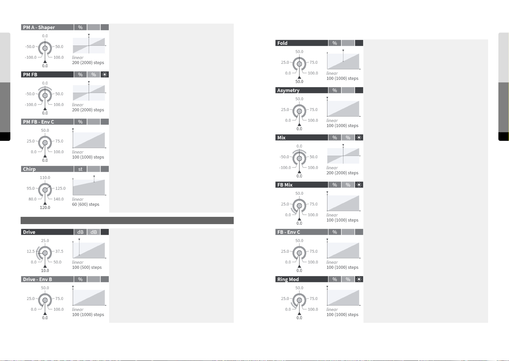
Shaper B
Parameter Reference
Mix amount of Shaper A in the signal being used for phase
modulation (A -> B). At zero, the output signal of Oscillator
A is used. At negative values, the signal from the Shaper is
inverted.
Amount of phase modulation by the Feedback signal.
Amount of folding back of the shaper curve for high input
amplitudes.
0.0 %: flat saturation, no folding
100 %: fully folded back (periodic sine curve)
A higher amount of folding leads to a soer but more nasal
sound.
Asymetry of the shaper curve, generating even (2nd, 4th, ...)
harmonics. At higher values it becomes a parabolic curve
that shis the frequency of the fundamental to its double.
Shaper B
Envelope (C) amount for the phase modulation by the
Feedback signal.
132 133
At zero, the modulation stays constant, at higher values, the
envelope applies a time-variant attenuation.
Cuto [in semitones] of the lowpass in the phase modulation
signal path that can be applied to reduce the level and
frequency of “chirping” appearing at higher amounts of self
modulation, cross-feedback through the other oscillator, or
global feedback.
Mix amount of Shaper B in the signal sent to the Filters
and to the Output Mixer. At zero, it is the input signal of the
Shaper - behind FB Mix. At negative values, the signal from
the Shaper is inverted.
Crossfades between Oscillator & Shaper B (at zero) and the
Feedback signal for the signal B.
Shaper B
Input gain [in dB] of the sine shaper stage. Higher gains will
create more distortion and harmonics.
Envelope (B) amount for the Drive factor.
At zero, the gain stays constant, at higher values, the envelope applies a time-variant attenuation.
Envelope (C) amount for the Feedback Mix. At zero, only a
Gate signal is applied, at higher values, Envelope C is faded
in.
Mix amount of the ring modulation between both Oscillators
& Shapers.
Parameter Reference
Page 68
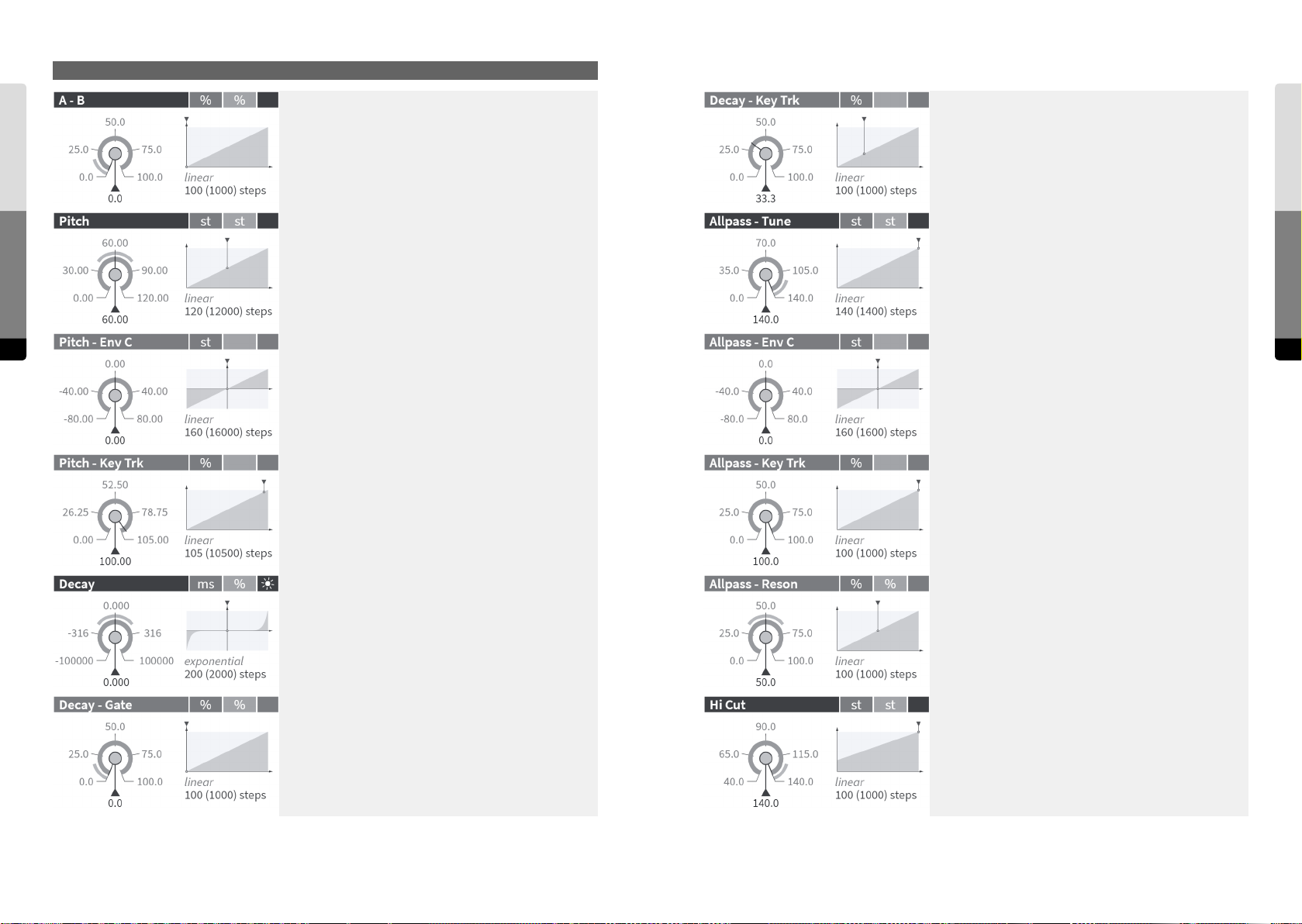
Comb Filter
Comb Filter
Parameter Reference
134 135
The signal for the Comb Filter as a crossfade between the
outputs of Oscillator & Shaper A and Oscillator & Shaper B.
Coarse pitch of the Comb Filter (delay) at C3 (MIDI note 60)
[in semitones, based on MIDI note numbers].
Amount of modulation of the Comb Filter pitch by Envelope
C [in semitones].
Key scaling of the tuning of the Comb Filter (delay).
0.0 %: same tuning for all keys
100.0 %: full tracking with keys, origin at C3 = 60 semitones
Key scaling of the decay time.
0.0 %: equal time for all keys
100.0 %: shortening to half time per octave, origin at C3 = 60
semitones
Center frequency of the 2-pole allpass filter [in semitones]. It
is the frequency where the phase is shied by 180 degrees.
The allpass is in series with the delay. At the maximum
position (140 semitones), the allpass has no eect.
Amount of modulation of the allpass center frequency by
Envelope C [in semitones].
Key scaling of the allpass filter frequency.
0.0 %: same tuning for all keys
100.0 %: full tracking with the keys, origin at C3 = 60 semitones
Comb Filter
Parameter Reference
Amount of the internal feedback noticeable as the decay
time of the impulse response [logarithmic scaling]. At
negative values, the feedback signal is inverted, which shis
the fundamental resonance down by one octave.
Amount of gating applied to the decay time. It reduces the
decay time when the key is released (Note-o).
0.0 % same decay time in the release phase
100.0 %: the decay time is set to zero at the release of the key
Resonance of the 2-pole allpass. Determines how much the
phase shi increases around the center frequency.
Cuto frequency [in semitones] of the lowpass filter that
damps the higher frequencies in the comb filter’s signal path.
Page 69
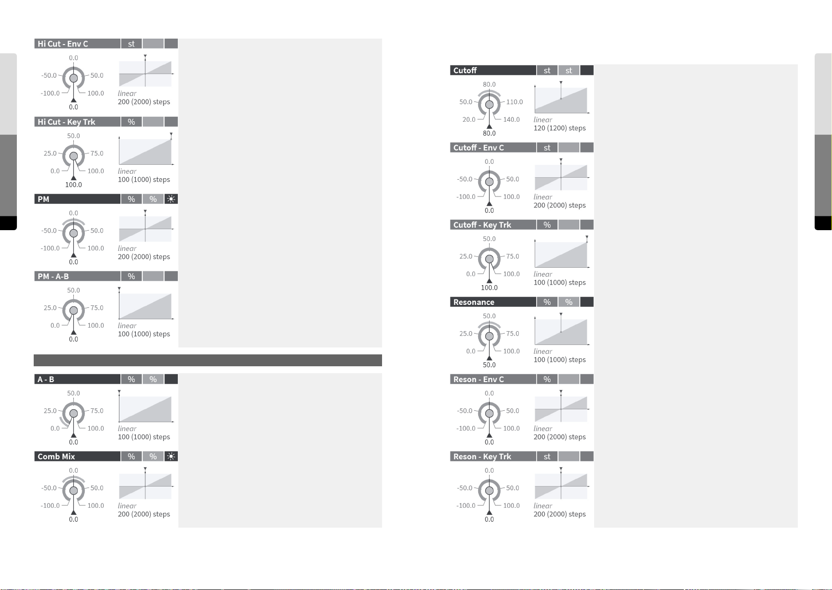
State Variable Filter
Amount of modulation of the cuto frequency of the lowpass
filter by Envelope C [in semitones].
Static value of the filter cuto frequency at C3 [in semitones],
applies to both stages of the filter. The osets between their
individual cutos is controlled by “Spread”.
Key scaling of the lowpass cuto frequency.
Parameter Reference
136 137
0.0 %: same cuto for all keys
100.0 %: full tracking with the keys, origin at C3 = 60 semitones
Amount of (phase) modulation of the comb filter pitch (delay
time) by the output signals of Oscillator & Shaper A and B,
with the PM A-B knob determining their mix.
The (phase) modulation signal for the Comb Filter as a
crossfade between the outputs of Oscillator & Shaper A and
Oscillator & Shaper B.
Amount of cuto modulation by Envelope C [in semitones].
Key scaling of the filter cutos.
0.0 %: no influence
100.0 %: full tracking with the keys, origin at C3 = 60 semitones
Amount of filter resonance, creating peaks at the cuto
frequencies.
State Variable Filter
The signal for the State Variable Filter as a crossfade between
the outputs of Oscillator & Shaper A and Oscillator & Shaper
B.
Amount of resonance modulation by Envelope C.
State Variable Filter
Parameter Reference
The input signal for the State Variable Filter as mix of the signals from the A-B mixer and from the Comb Filter. Negative
mix amounts will create dierent Comb Filter (cancellation)
eects.
Key scaling of the filter resonance.
0.0 %: no influence
100.0 %: full tracking with the keys, origin at C3 = 60 semitones
Page 70
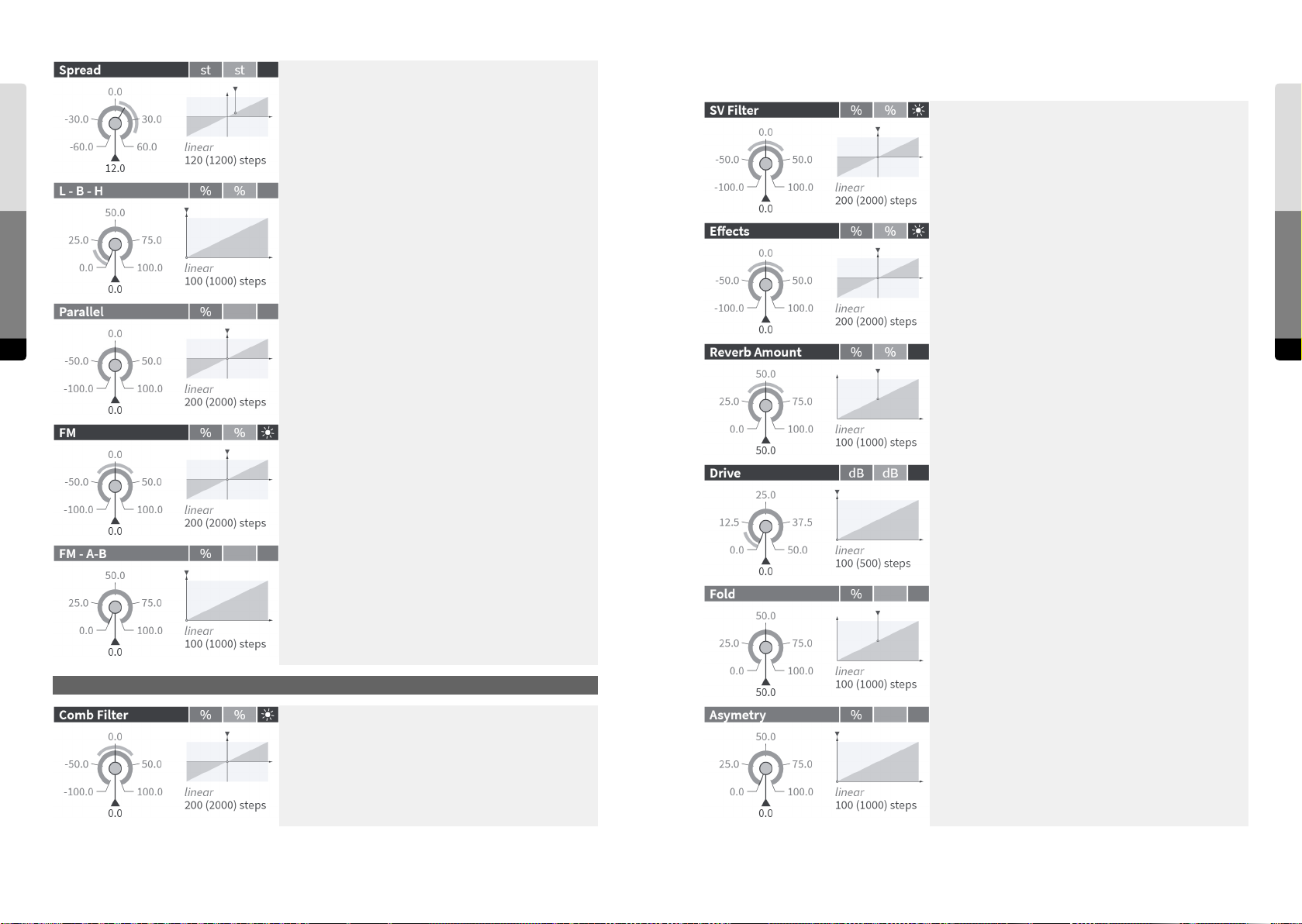
Amount of splitting of the cutos of the two 2-pole filters.
Feedback Mixer
Parameter Reference
138 139
Half of the value is applied as a positive oset to the adjusted
cuto for the first stage and as a negative oset for the
second stage [in semitones].
The split reduces the strong resonance peak in the 4-pole
mode and allows filter curves with two formants. In bandpass/bandreject mode it controls the width of the band.
Crossfades between the lowpass, bandpass and highpass
outputs of the two filter stages.
(first stage -> second stage: LP -> LP, BP -> LP, HP -> LP, HP ->
BP, HP -> HP)
At zero, the two 2-pole filter stages are in series forming a
4-pole filter. Positive values crossfade to a parallel structure
where the filter outputs are added. In bandpass mode (L-B-H
= 50.0%), the parallel structure with a negative Spread works
as a band-reject filter. Negative values also crossfade to a
parallel structure, but here the lower filter is subtracted,
which leads to phase cancellations.
Amount of modulation of the cuto frequencies by the
output signals of Oscillator & Shaper A and B, with the FM
A-B knob determining their mix. The amount is relative to the
cuto frequency.
Feedback mix factor for the output of the State Variable
Filter.
Feedback mix factor for the output of the Eects chain. The
reverb amount in the feedback can be set by the “Reverb
Amount” fader independantly. Since the signal is monophonic, such feedback will cause intermodulation between
the voices.
Controls the amount of reverb in the feedback independantly from the Mix in the Reverb section.
0.0 %: dry, no reverb signal
50.0 %: mix of 50 % dry and 50 % wet signal
100.0 %: wet, 100 % reverb signal
Input gain [in dB] of the sine shaper stage. Higher gains will
create more distortion and harmonics.
Feedback Mixer
Parameter Reference
The signal for the FM (cuto frequency modulation) of the
State Variable Filter as a crossfade between the outputs of
Oscillator & Shaper A and Oscillator & Shaper B.
Feedback Mixer
Feedback mix factor for the output of the Comb Filter.
Amount of folding back of the shaper curve for high input
amplitudes.
0.0 %: flat saturation, no folding
100.0 %: fully folded back (periodic sine curve)
A higher amount of folding leads to a soer but more nasal
sound.
Asymetry of the shaper curve, generating even (2nd, 4th, ...)
harmonics. At higher values, it becomes a parabolic curve
that shis the frequency of the fundamental to its double.
Page 71

Level of the (global) Feedback mix [in dB].
Output Mixer
Parameter Reference
Key scaling of the feedback level [in dB per semitone].
positive values: higher level for higher notes (+ 1.0 = + 12 dB
per octave)
negative values: lower level for higher notes (- 1.0 = - 12 dB
per octave)
origin at C3 = 60 semitones
Output mix factor for the signal from the Comb Filter.
Pan position of the signal from the Comb Filter in the output
mix.
Output Mixer
140 141
Output mix factor for the signal from Oscillator & Shaper A.
Output mix factor for the signal from Oscillator & Shaper A.
Output mix factor for the signal from the State Variable Filter.
Pan position of the signal from the State Variable Filter in the
output mix.
Output Mixer
Parameter Reference
Output mix factor for the signal from Oscillator & Shaper B.
Output mix factor for the signal from Oscillator & Shaper B.
Input gain [in dB] of the sine shaper stage. Higher gains will
create more distortion and harmonics.
Amount of folding back of the shaper curve for high input
amplitudes.
0.0 %: flat saturation, no folding
100.0 %: fully folded back (periodic sine curve)
A higher amount of folding leads to a soer but more nasal
sound.
Page 72
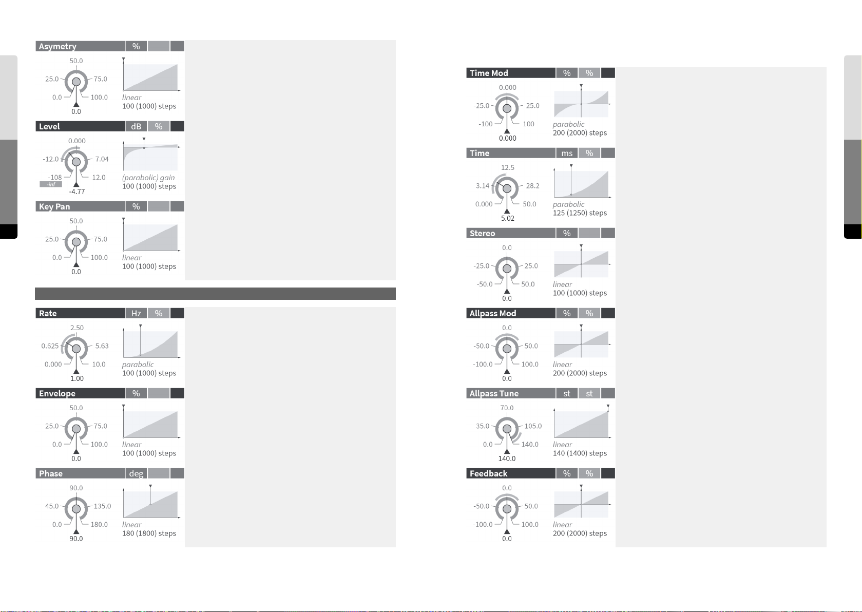
Asymetry of the shaper curve, generating even (2nd, 4th, ...)
harmonics. At higher values, it becomes a parabolic curve
that shis the frequency of the fundamental to its double.
Flanger
Master output level [in dB] of the synth. The output signal
Parameter Reference
142 143
will be processed by the (monophonic) chain of eects.
Amount of key panning for each note (referring to the key
position relative to the center at C3 = 60 semitones).
At zero, each note is centered before being passed to the
panning section in the mix.
At maximum, low notes will be panned to the le, high notes
to the right.
Relative amount of the modulation of the delay times by the
LFO and/or the envelope.
Mean value of the delay times in the le and right channel.
The “Stereo” parameter allows to create a time oset
between the channels.
When the time of the Flanger is set to zero, the overall eect
is determined by the phase shiing of the allpass.
Sets the ratio between the delay times of the le and of the
right channel [the value shows the oset to 100.0 %]. In the
center position, the oset is zero and both delay times are
equal.
Flanger
Flanger
Parameter Reference
Frequency of the LFO and rate of the envelope. Both can
be modulation sources for the delay times and the allpass
center frequencies.
Crossfades between the signals of the LFO and the envelope
as modulation sources for the delay times and the allpass
center frequencies.
Phase oset between the LFO signals modulating the delay
times in the le and the right channel.
Relative amount of the modulation of the allpass center
frequencies by the LFO and/or the envelope. The allpass
creates the eect of a phaser.
Mean center frequency of the 4-pole allpass filters which
are in series with the delays. Their frequency-dependant
phase shis can create a “Phaser” eect. The phase shi is
minimized by setting this control to its maximum. When the
time of the flanger is set to zero, the allpass becomes the
dominant part.
Amount of the internal feedback. At negative values, the
feedback is inverted and will emphasize other frequencies
than in the non-inverted mode.
Page 73
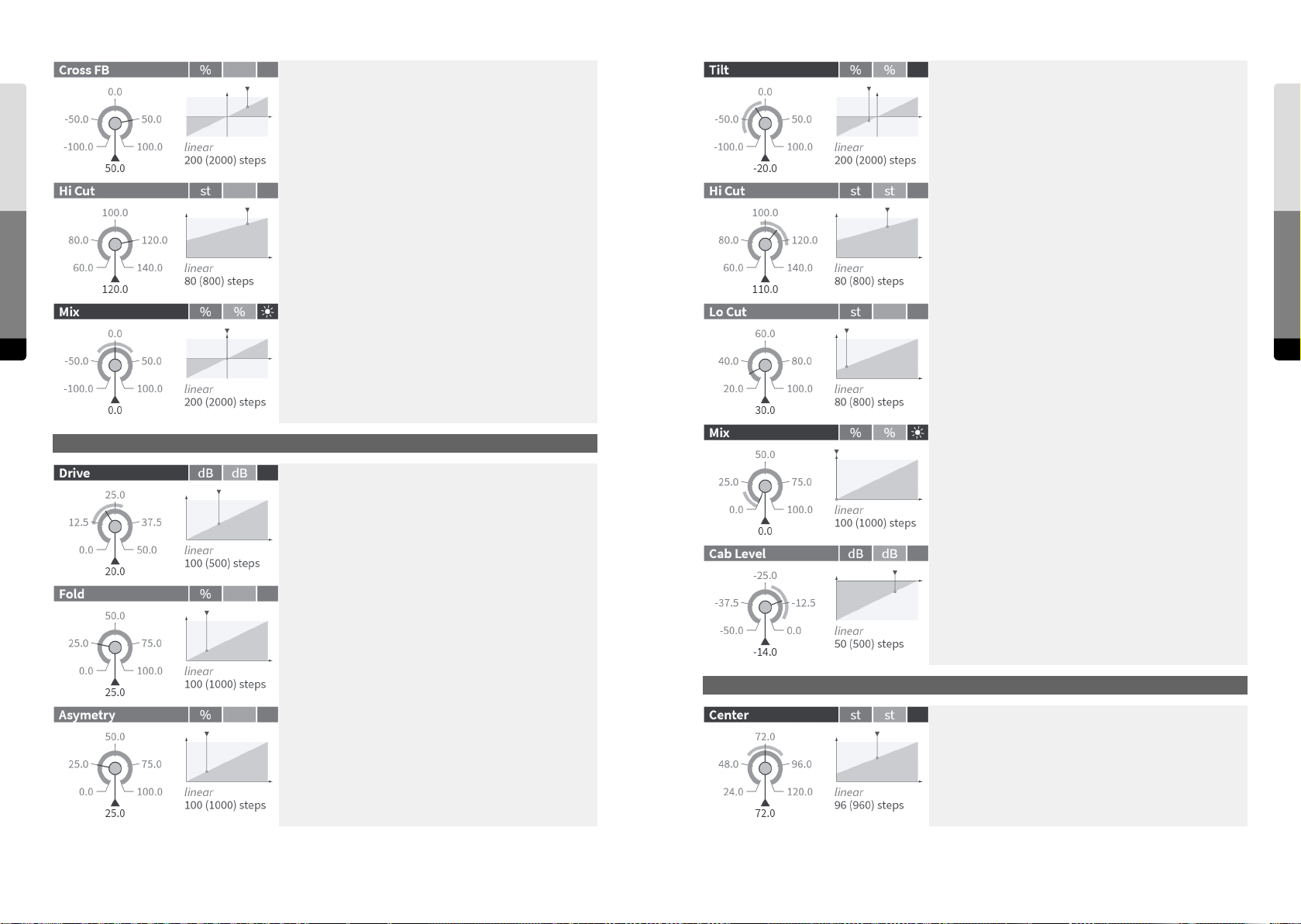
Amount of the cross feedback between the le and the right
channel, increasing the complexity of the resulting signal.
At negative values, the cross feedback is inverted and will
Cabinet
emphasize other frequencies than in the non-inverted mode.
0.0 %: no cross feedback
+/- 100.0 %: all feedback is cross feedback
Controls two inverted shelving EQs before and aer the
distortion stage.
negative: more distortions at high frequencies
positive: more distortions at low frequencies
Gap Filter
Cuto frequency [in semitones] of the filter that damps the
Parameter Reference
higher frequencies of the delayed signal.
Cuto frequency [in semitones] of the lowpass filter at the
output.
Crossfades between the dry signal and the delayed signal. At
negative values, the delayed signal is inverted.
Cuto frequency [in semitones] of the highpass filter at the
input.
144 145
Cabinet
Gain [in dB] for the input signal. Higher gains will increase
the amount of distortion/saturation.
Amount of folding back of the shaper curve for high input
amplitudes.
0.0 %: flat saturation, no folding
100.0 %: fully folded back (periodic sine curve)
A higher amount of folding leads to a soer but more nasal
sound.
Asymetry of the shaper curve, generating even (2nd, 4th, ...)
harmonics. At higher values, it becomes a parabolic curve
that shis the frequency of the fundamental to its double.
Crossfades between the dry signal and the saturated signal.
Output level [in dB] of the saturation eect before it is mixed
with the dry signal.
Gap Filter
Shis the mean cuto frequency of both 4-pole filters on
both channels up or down [in semitones].
Parameter Reference
Page 74
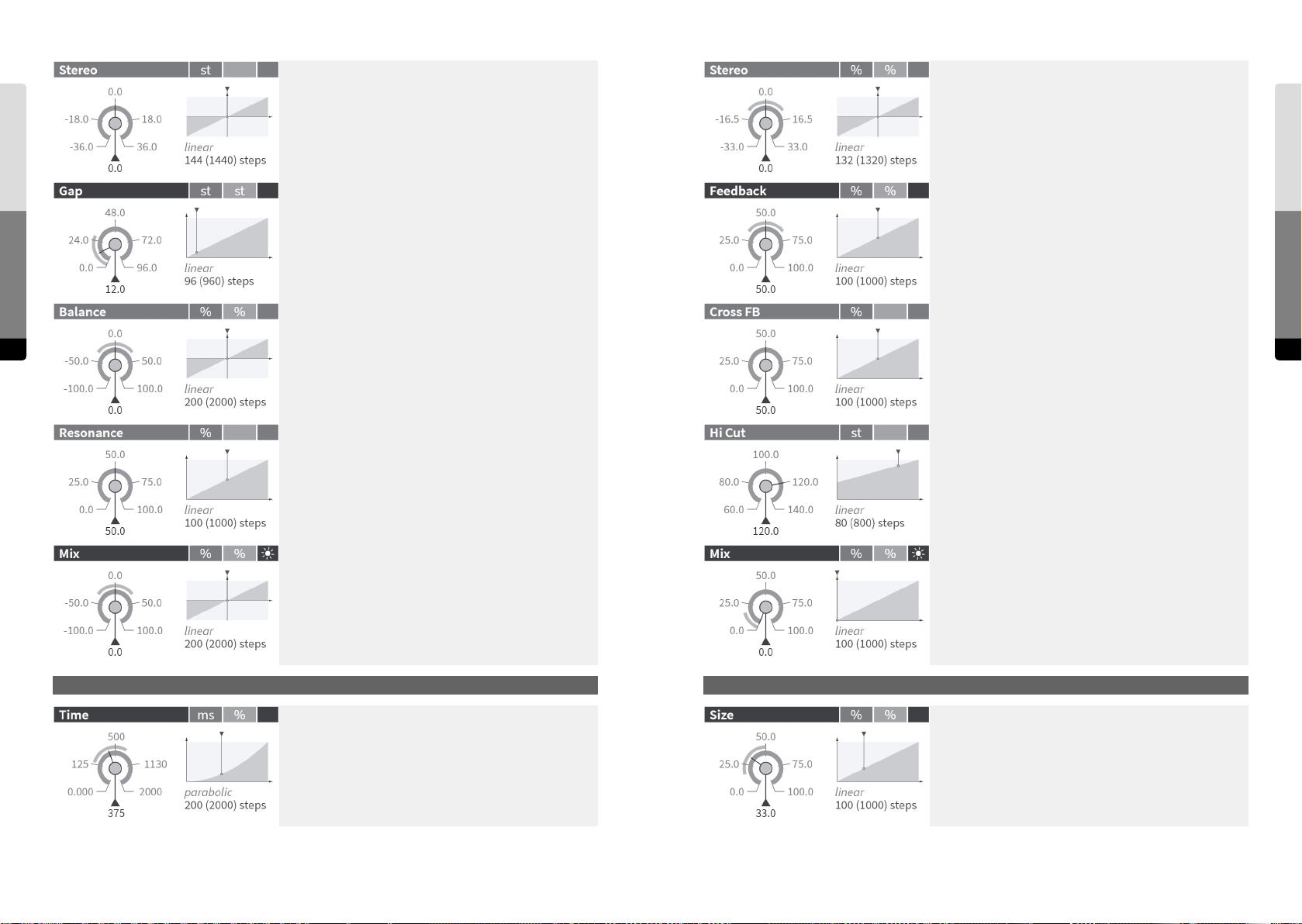
Echo
Sets the dierence between the center frequencies of the le
and of the right channel [in semitones].
Sets the ratio between the delay times of the le and of the
right channel [the value shows the oset to 100.0 %]. In the
center position, the oset is zero and both delay times are
equal.
Reverb
Oset between the cutos of the lowpass and the highpass
Parameter Reference
146 147
[in semitones]. Since the two filters are running in parallel
and their output signals are mixed, the result of a positive
gap is a band rejection. With a negative gap, the pass bands
are overlapping so that all frequencies can pass and the
resonances emphasize the cuto frequencies.
Balance between the levels of the ranges above and below
the gap.
In the center position both ranges are equally weighted.
Negative values boost the lower range and attenuate the
higher range, positive values have the opposite eect.
Resonance of both filters. Higher values create two resonance peaks at the upper and lower end of the gap.
Crossfades between the dry signal and the filtered signal. At
positive values, the filter runs in parallel (band reject) mode,
at negative values, it is a bandpass filter (in serial mode).
Amount of internal feedback.
Amount of the cross feedback between the le and right
channel.
0.0 %: no cross feedback
100.0 %: all feedback is cross feedback
Cuto frequency [in semitones] of the filter that damps the
higher frequencies of the delayed signal.
Crossfades between the dry signal and the delayed signal.
Parameter Reference
Echo
Mean delay time [in milliseconds]. (As there can be an oset
between the le and right channel, this control shows the
mean time.)
Reverb
The room size and reverb time are set here.
Page 75
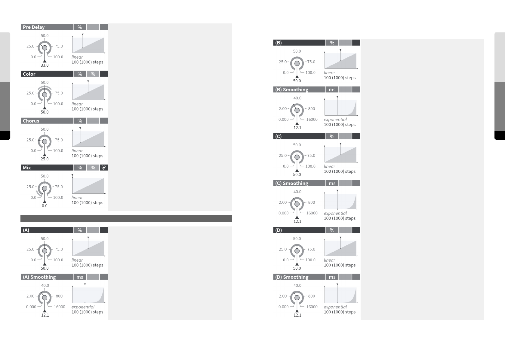
Pre delay time, shiing the late reflections. This has a
profound eect on the perceived room size.
Macros
The info text of Macro Control B is user-definable and
defaults to an empty string.
Macros
Cuto of the filter that damps the lower frequencies of the
Parameter Reference
reverberation signal.
Sets the smoothing time [in milliseconds] for modulations
on target parameters assigned to Macro Control B. At zero,
assigned target parameters will follow the Macro Control
immediately.
This controls the internal modulation of the reverberation
delays. At higher amounts, there is more movement and the
148 149
diusion is smoother. At lower amounts, the reverb becomes
more static and metallic.
Crossfades between the dry signal and the reverberation
signal.
The info text of Macro Control C is user-definable and
defaults to an empty string.
Sets the smoothing time [in milliseconds] for modulations
on target parameters assigned to Macro Control C. At zero,
assigned target parameters will follow the Macro Control
immediately.
Macros
The info text of Macro Control A is user-definable and
defaults to an empty string.
Sets the smoothing time [in milliseconds] for modulations
on target parameters assigned to Macro Control A. At zero,
assigned target parameters will follow the Macro Control
immediately.
The info text of Macro Control D is user-definable and
defaults to an empty string.
Sets the smoothing time [in milliseconds] for modulations
on target parameters assigned to Macro Control D. At zero,
assigned target parameters will follow the Macro Control
immediately.
Parameter Reference
Page 76
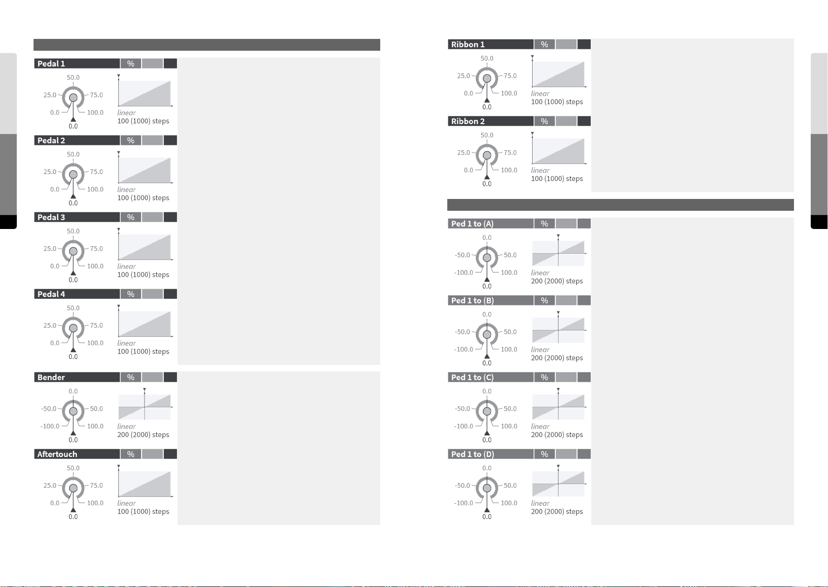
Hardware Sources
Hardware Sources
This control is the parameter representation of the “Pedal
1” Hardware Source. If a pedal is connected, it will directly
follow the external control. If the source’s return behavior is
set to “Center”, the parameter will be bipolar.
This control is the parameter representation of the “Ribbon
1” Hardware Source. It will directly follow the Ribbon and
vice versa. If the source’s return behavior is set to “Center”,
the parameter will be bipolar.
This control is the parameter representation of the “Ribbon
Parameter Reference
This control is the parameter representation of the “Pedal
2” Hardware Source. If a pedal is connected, it will directly
follow the external control. If the source’s return behavior is
set to “Center”, the parameter will be bipolar.
2” Hardware Source. It will directly follow the Ribbon and
vice versa. If the source’s return behavior is set to “Center”,
the parameter will be bipolar.
Hardware Amounts
150 151
This control is the parameter representation of the “Pedal
3” Hardware Source. If a pedal is connected, it will directly
follow the external control. If the source’s return behavior is
set to “Center”, the parameter will be bipolar.
This control is the parameter representation of the “Pedal
4” Hardware Source. If a pedal is connected, it will directly
follow the external control. If the source’s return behavior is
set to “Center”, the parameter will be bipolar.
This control is the parameter representation of the “Bender”
Hardware Source. It will directly follow the Bender.
Determines the influence of the “Pedal 1” Hardware Source
on Macro Control A.
If the Pedal is a returning Hardware Source, the amount can
be adjusted continuously, otherwise it will be switch-like.
Continuous amounts can be set [in percent] and can cover
the whole range of the Macro Control in both directions
(-100.0 % … 100.0 %).
Determines the influence of the “Pedal 1” Hardware Source
on Macro Control B. If the Pedal is a returning Hardware
Source, the amount can be adjusted continuously, otherwise
it will be switch-like. Continuous amounts can be set [in
percent] and can cover the whole range of the Macro Control
in both directions (-100.0 % … 100.0 %).
Determines the influence of the “Pedal 1” Hardware Source
on Macro Control C. If the Pedal is a returning Hardware
Source, the amount can be adjusted continuously, otherwise
it will be switch-like. Continuous amounts can be set [in
percent] and can cover the whole range of the Macro Control
in both directions (-100.0 % ... 100.0 %).
Hardware Amounts
Parameter Reference
This control is the parameter representation of the “Aertouch” Hardware Source. It will directly follow Aertouch
gestures.
Determines the influence of the “Pedal 1” Hardware Source
on Macro Control D. If the Pedal is a returning Hardware
Source, the amount can be adjusted continuously, otherwise
it will be switch-like. Continuous amounts can be set [in
percent] and can cover the whole range of the Macro Control
in both directions (-100.0 % … 100.0 %).
Page 77
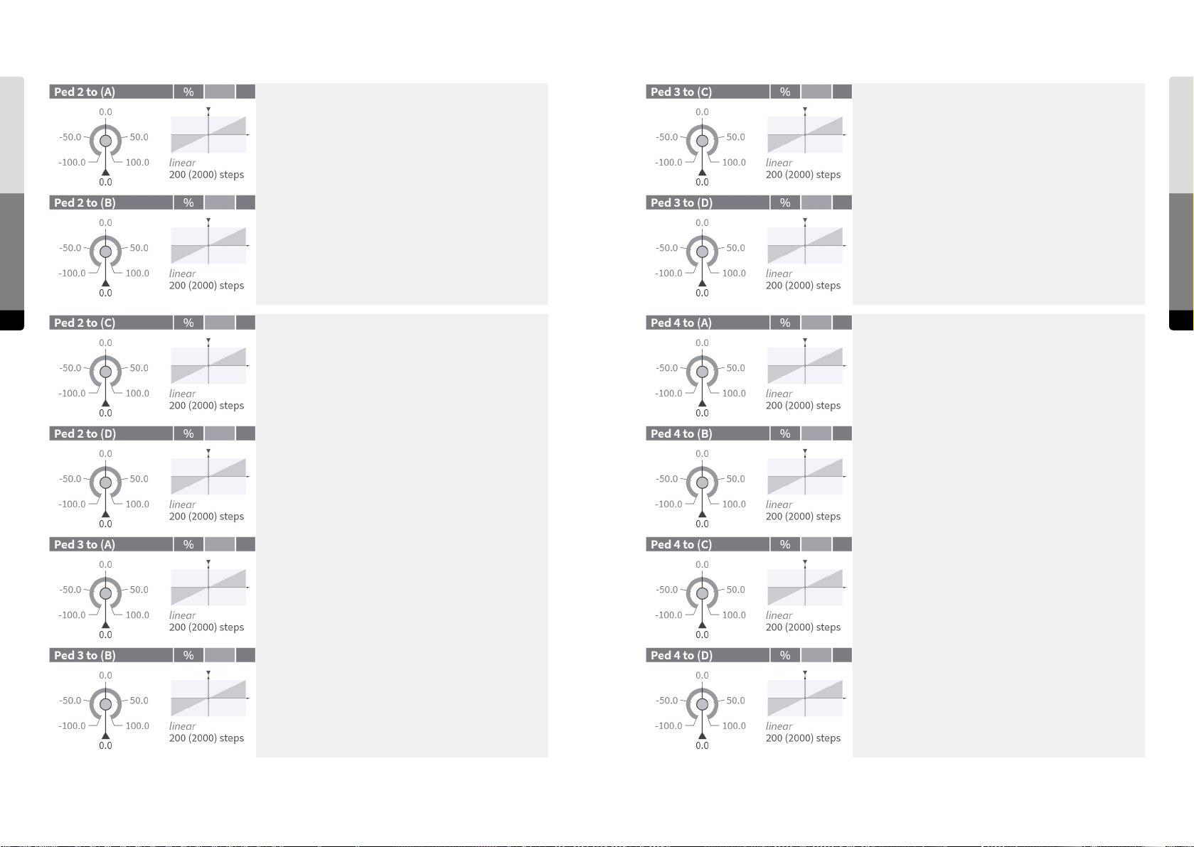
Hardware Amounts
Parameter Reference
152 153
Determines the influence of the “Pedal 2” Hardware Source
on Macro Control A. If the Pedal is a returning Hardware
Source, the amount can be adjusted continuously, otherwise
it will be switch-like. Continuous amounts can be set [in
percent] and can cover the whole range of the Macro Control
in both directions (-100.0 % … 100.0 %).
Determines the influence of the “Pedal 2” Hardware Source
on Macro Control B. If the Pedal is a returning Hardware
Source, the amount can be adjusted continuously, otherwise
it will be switch-like. Continuous amounts can be set [in
percent] and can cover the whole range of the Macro Control
in both directions (-100.0 % … 100.0 %).
Determines the influence of the “Pedal 2” Hardware Source
on Macro Control C. If the Pedal is a returning Hardware
Source, the amount can be adjusted continuously, otherwise
it will be switch-like. Continuous amounts can be set [in
percent] and can cover the whole range of the Macro Control
in both directions (-100.0 % … 100.0 %).
Determines the influence of the “Pedal 3” Hardware Source
on Macro Control C. If the Pedal is a returning Hardware
Source, the amount can be adjusted continuously, otherwise
it will be switch-like. Continuous amounts can be set [in
percent] and can cover the whole range of the Macro Control
in both directions (-100.0 % … 100.0 %).
Determines the influence of the “Pedal 3” Hardware Source
on Macro Control D. If the Pedal is a returning Hardware
Source, the amount can be adjusted continuously, otherwise
it will be switch-like. Continuous amounts can be set [in
percent] and can cover the whole range of the Macro Control
in both directions (-100.0 % … 100.0 %).
Determines the influence of the “Pedal 4” Hardware Source
on Macro Control A. If the Pedal is a returning Hardware
Source, the amount can be adjusted continuously, otherwise
it will be switch-like. Continuous amounts can be set [in
percent] and can cover the whole range of the Macro Control
in both directions (-100.0 % … 100.0 %).
Hardware Amounts
Parameter Reference
Determines the influence of the “Pedal 2” Hardware Source
on Macro Control D. If the Pedal is a returning Hardware
Source, the amount can be adjusted continuously, otherwise
it will be switch-like. Continuous amounts can be set [in
percent] and can cover the whole range of the Macro Control
in both directions (-100.0 % … 100.0 %).
Determines the influence of the “Pedal 3” Hardware Source
on Macro Control A. If the Pedal is a returning Hardware
Source, the amount can be adjusted continuously, otherwise
it will be switch-like. Continuous amounts can be set [in
percent] and can cover the whole range of the Macro Control
in both directions (-100.0 % … 100.0 %).
Determines the influence of the “Pedal 3” Hardware Source
on Macro Control B. If the Pedal is a returning Hardware
Source, the amount can be adjusted continuously, otherwise
it will be switch-like. Continuous amounts can be set [in
percent] and can cover the whole range of the Macro Control
in both directions (-100.0 % … 100.0 %).
Determines the influence of the “Pedal 4” Hardware Source
on Macro Control B. If the Pedal is a returning Hardware
Source, the amount can be adjusted continuously, otherwise
it will be switch-like. Continuous amounts can be set [in
percent] and can cover the whole range of the Macro Control
in both directions (-100.0 % … 100.0 %).
Determines the influence of the “Pedal 4” Hardware Source
on Macro Control C. If the Pedal is a returning Hardware
Source, the amount can be adjusted continuously, otherwise
it will be switch-like. Continuous amounts can be set [in
percent] and can cover the whole range of the Macro Control
in both directions (-100.0 % … 100.0 %).
Determines the influence of the “Pedal 4” Hardware Source
on Macro Control D. If the Pedal is a returning Hardware
Source, the amount can be adjusted continuously, otherwise
it will be switch-like. Continuous amounts can be set [in
percent] and can cover the whole range of the Macro Control
in both directions (-100.0 % … 100.0 %).
Page 78
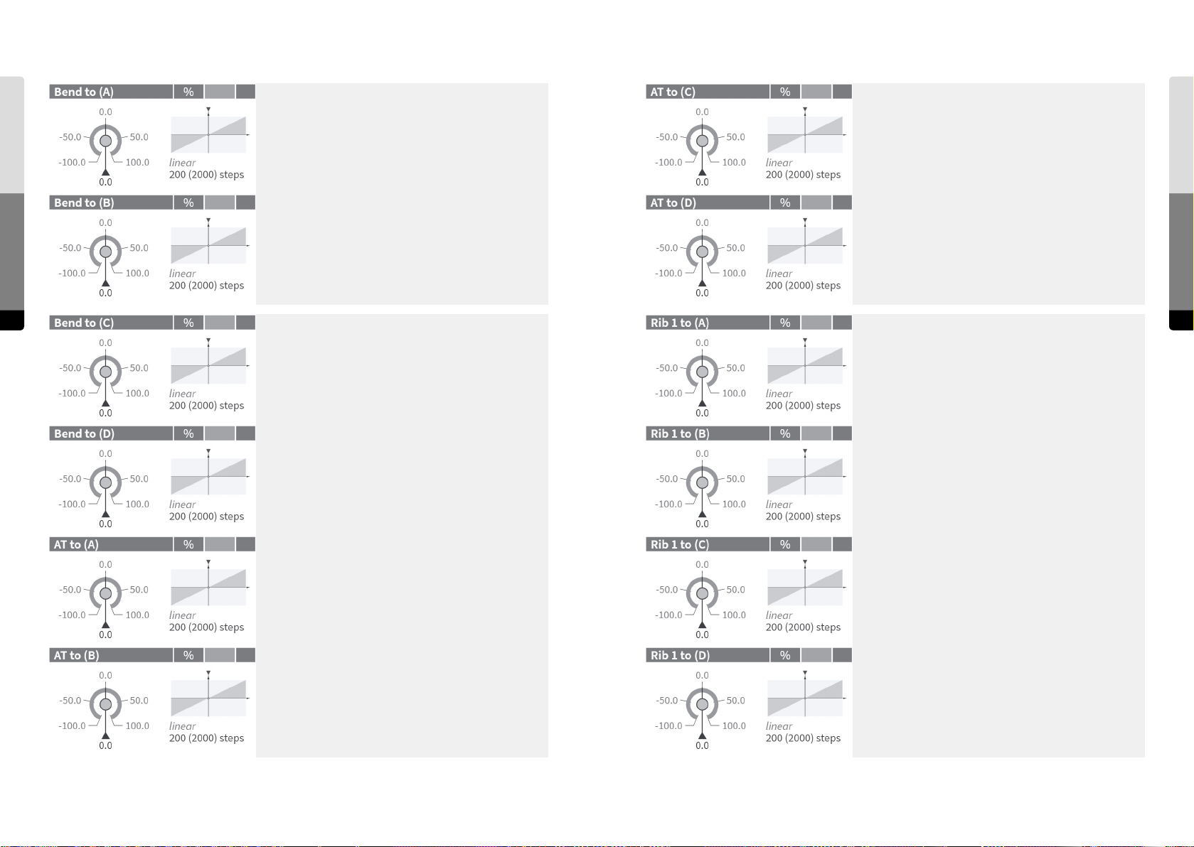
Hardware Amounts
Parameter Reference
154 155
Determines the influence of the “Bender” Hardware Source
on Macro Control A.
The amount can be adjusted continuously [in percent] and
can cover the whole range of the Macro Control in both
directions (-100.0 % … 100.0 %).
Determines the influence of the “Bender” Hardware Source
on Macro Control B.
The amount can be adjusted continuously [in percent] and
can cover the whole range of the Macro Control in both
directions (-100.0 % … 100.0 %).
Determines the influence of the “Bender” Hardware Source
on Macro Control C.
The amount can be adjusted continuously [in percent] and
can cover the whole range of the Macro Control in both
directions (-100.0 % … 100.0 %).
Determines the influence of the “Aertouch” Hardware
Source on Macro Control C.
The amount can be adjusted continuously [in percent] and
can cover the whole range of the Macro Control in both
directions (-100.0 % … 100.0 %).
Determines the influence of the “Aertouch” Hardware
Source on Macro Control D.
The amount can be adjusted continuously [in percent] and
can cover the whole range of the Macro Control in both
directions (-100.0 % … 100.0 %).
Determines the influence of the “Ribbon 1” Hardware Source
on Macro Control A. If the Ribbon is a returning Hardware
Source, the amount can be adjusted continuously, otherwise
it will be switch-like. Continuous amounts can be set [in
percent] and can cover the whole range of the Macro Control
in both directions (-100.0 % … 100.0 %).
Hardware Amounts
Parameter Reference
Determines the influence of the “Bender” Hardware Source
on Macro Control D.
The amount can be adjusted continuously [in percent] and
can cover the whole range of the Macro Control in both
directions (-100.0 % … 100.0 %).
Determines the influence of the “Aertouch” Hardware
Source on Macro Control A.
The amount can be adjusted continuously [in percent] and
can cover the whole range of the Macro Control in both
directions (-100.0 % … 100.0 %).
Determines the influence of the “Aertouch” Hardware
Source on Macro Control B.
The amount can be adjusted continuously [in percent] and
can cover the whole range of the Macro Control in both
directions (-100.0 % … 100.0 %).
Determines the influence of the “Ribbon 1” Hardware Source
on Macro Control B. If the Ribbon is a returning Hardware
Source, the amount can be adjusted continuously, otherwise
it will be switch-like. Continuous amounts can be set [in
percent] and can cover the whole range of the Macro Control
in both directions (-100.0 % … 100.0 %).
Determines the influence of the “Ribbon 1” Hardware Source
on Macro Control C. If the Ribbon is a returning Hardware
Source, the amount can be adjusted continuously, otherwise
it will be switch-like. Continuous amounts can be set [in
percent] and can cover the whole range of the Macro Control
in both directions (-100.0 % … 100.0 %).
Determines the influence of the “Ribbon 1” Hardware Source
on Macro Control D. If the Ribbon is a returning Hardware
Source, the amount can be adjusted continuously, otherwise
it will be switch-like. Continuous amounts can be set [in
percent] and can cover the whole range of the Macro Control
in both directions (-100.0 % … 100.0 %).
Page 79
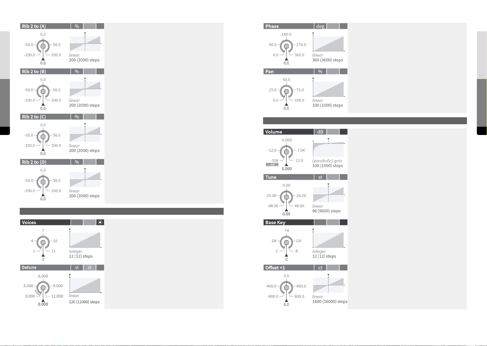
Unison
Determines the influence of the “Ribbon 2” Hardware Source
on Macro Control A. If the Ribbon is a returning Hardware
Source, the amount can be adjusted continuously, otherwise
it will be switch-like. Continuous amounts can be set [in
percent] and can cover the whole range of the Macro Control
in both directions (-100.0 % … 100.0 %).
Spreading the (Oscillators’) start phases of the unison voices
to get dierent phase cancellations at the beginning of a
note. The value is the phase range [in degrees] covered by a
group of unison voices.
Determines the influence of the “Ribbon 2” Hardware Source
Parameter Reference
156 157
on Macro Control B. If the Ribbon is a returning Hardware
Source, the amount can be adjusted continuously, otherwise
it will be switch-like. Continuous amounts can be set [in
percent] and can cover the whole range of the Macro Control
in both directions (-100.0 % … 100.0 %).
Determines the influence of the “Ribbon 2” Hardware Source
on Macro Control C. If the Ribbon is a returning Hardware
Source, the amount can be adjusted continuously, otherwise
it will be switch-like. Continuous amounts can be set [in
percent] and can cover the whole range of the Macro Control
in both directions (-100.0 % … 100.0 %).
Determines the influence of the “Ribbon 2” Hardware Source
on Macro Control D. If the Ribbon is a returning Hardware
Source, the amount can be adjusted continuously, otherwise
it will be switch-like. Continuous amounts can be set [in
percent] and can cover the whole range of the Macro Control
in both directions (-100.0 % … 100.0 %).
Voice panning inside of a group of unison voices. At 100.0 %,
the voices are spread over the full stereo base.
Master / Scale Group
Master volume [in dB], applied at the end of the eect chain,
before the so clipper.
Global pitch transposition [in semitones].
Unison
Number of unison voices that will be assigned to a key. At 1,
the unison eect is disabled.
Sets the base key for the custom scale. The scale is defined
for the eleven keys above the base key and will be applied to
all octaves accordingly.
Master / Scale
Parameter Reference
Spreading of the pitches of the unison voices [in semitones].
The Fine mode allows for adjustments in steps of 0.001
semitones (0.1 cents).
Oset of the first key following the base key [in cents]. At
zero, the interval to the base key would be the minor second
of the equally tempered scale.
Page 80
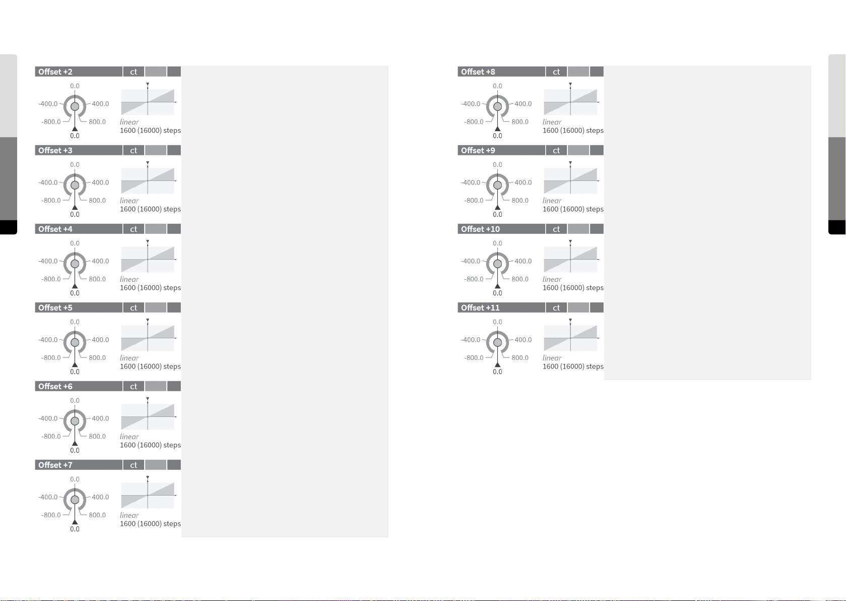
Master / Scale
Oset of the second key following the base key [in cents]. At
zero, the interval to the base key would be the major second
of the equally tempered scale.
Oset of the 8th key following the base key [in cents]. At zero,
the interval to the base key would be the minor sixth of the
equally tempered scale.
Parameter Reference
Oset of the third key following the base key [in cents]. At
zero, the interval to the base key would be the minor third of
the equally tempered scale.
158 159
Oset of the 4th key following the base key [in cents]. At zero,
the interval to the base key would be the major third of the
equally tempered scale.
Oset of the 9th key following the base key [in cents]. At zero,
the interval to the base key would be the major sixth of the
equally tempered scale.
Oset of the 10th key following the base key [in cents]. At
zero, the interval to the base key would be the minor seventh
of the equally tempered scale.
Master / Scale
Parameter Reference
Oset of the 5th key following the base key [in cents]. At
zero, the interval to the base key would be the quarter of the
equally tempered scale.
Oset of the 6th key following the base key [in cents]. At
zero, the interval to the base key would be the tritone of the
equally tempered scale.
Oset of the 7th key following the base key [in cents]. At zero,
the interval to the base key would be the fih of the equally
tempered scale.
Oset of the 11th key following the base key [in cents]. At
zero, the interval to the base key would be the major seventh
of the equally tempered scale.
Page 81

10. Shortcuts for the Graphical User Interface
UI Components
Ctrl + P . . . . . . . . . show/hide Presets
Ctrl + E . . . . . . . . . show/hide Parameters
Tab s
GUI Shortcuts
160 161
Shi + P . . . . . . . . show/hide Preset tab
Shi + E . . . . . . . . show/hide Parameter tab
Shi + N . . . . . . . . show/hide Sound tab
Windows
I . . . . . . . . . . . . show/hide Parameter Info window
P . . . . . . . . . . .show/hide Preset Info window
B . . . . . . . . . . .show/hide Bank Info window
U . . . . . . . . . . .show/hide Undo History window
Context Menus:
Ctrl + Click
Long Touch
Right Mousebutton . .open the local context menu
Esc . . . . . . . . . .close the local context menu
Banks/Presets
Right Arrow . . . . . . select next Bank
Le Arrow . . . . . . . select previous Bank
Down Arrow . . . . . . select next Preset
Up Arrow . . . . . . .select previous Preset
Mousewheel on
bank in Preset tab . . select previous/next preset (depends on direction)
Enter . . . . . . . . . load/reload selected Preset
Del . . . . . . . . . .delete the selected Preset(s)
D . . . . . . . . . . .enable/disable Direct Load (and open the Preset toolbar)
Shi + Click on Preset . start Multiple Selection
Click on background finish Multiple Selection (and restore the previous selection)
Shi + Mouse frame. . select multiple Presets
Preset Store
S . . . . . . . . . . . activate Store Select mode (and open the Preset tab)
Enter . . . . . . . . . apply Store (and finish the Store Select mode)
Ctrl + S . . . . . . . . store Preset at current position
(depending on Append/Insert/Overwrite)
Rename
R . . . . . . . . . . open the Rename dialog
Enter . . . . . . . . . Apply (and close the dialog)
Esc. . . . . . . . . . Cancel (and close the dialog)
Parameter Editing
K . . . . . . . . . . increment value, coarse
Shi + K . . . . . . . increment value, fine
M . . . . . . . . . . decrement value, coarse
Shi + M . . . . . . . decrement value, fine
Double Click . . . . . set to Default value
Drag on parameter . . . adjust parameter control position
Mousewheel on
Parameter tab . . . . . adjust selected parameter control position
Search
F . . . . . . . . . . . open Preset Search dialog
Esc. . . . . . . . . . finish Search (and close the dialog)
Undo/Redo
Ctrl + Z . . . . . . . . Undo
Ctrl + Y . . . . . . . . Redo
Help
Ctrl + H . . . . . . . . open HTML Help (in new browser tab)
Panning
Space + Drag . . . . . temporarily lock the interface (parameters/banks) in order to
allow panning gestures on them
Zooming
Double Click on background . . . 1st time: zoom to standard position and scale
2nd time: back to last zoom position and scale
Double Click on group header 1st time: zoom group to fullscreen
2nd time: back to last zoom position and scale
Mousewheel on main area . . . . adjust zoom level directly
GUI Shortcuts
 Loading...