

nomad TRANS-FLO NTG40 Operation Manual

OPERATION MANUAL
NTG40 NOMAD TRANS-FLO™
AIR-OPERATED • DOUBLE DIAPHRAGM • PUMPS
ALUMINUM Models
DUCTILE IRON Models
316 STAINLESS STEEL Models
A JDA Global Company
NTG40 NOMAD TRANS-FLO™
CAUTION – SAFETY POINTS
TEMPERATURE LIMITS:
Neoprene -17.8°C to 93.3°C 0°F to 200°F
Buna-N -12.2°C to 82.2°C 10°F to 180°F
EPDM -51.1°C to 137.8°C -60°F to 280°F
Viton® -40°C to 176.7°C -40°F to 350°F
Santoprene® -40°C to 107.2°C -40°F to 225°F
Polyurethane 12.2°C to 65.6°C 10°F to 150°F
Hytrel® -28.9°C to 104.4°C -20°F to 220°F
PTFE 4.4°C to 104.4°C 40°F to 220°F
1. Review the NOMAD Chemical Field Guide
for all applications. The information
provided is the “best thinking available”
regarding chemical compatibility. The
guide however, does not provide a
recommendation.
2. Always wear safety glasses during pump
operation. A diaphragm rupture may force
liquid to exit via air exhaust.
3. When handling ammable uids, prevent
static sparking by properly grounding
the pump.
4. Do not exceed 125 psig (8.6 bar).
5. Prior to maintenance, compressed air
line should be disconnected to allow air
pressure to bleed from pump.
6. Tighten all clamp bands and hardware
parts prior to installation. Fittings may
loosen during transportation.
1
NTG40 NOMAD TRANS-FLO™
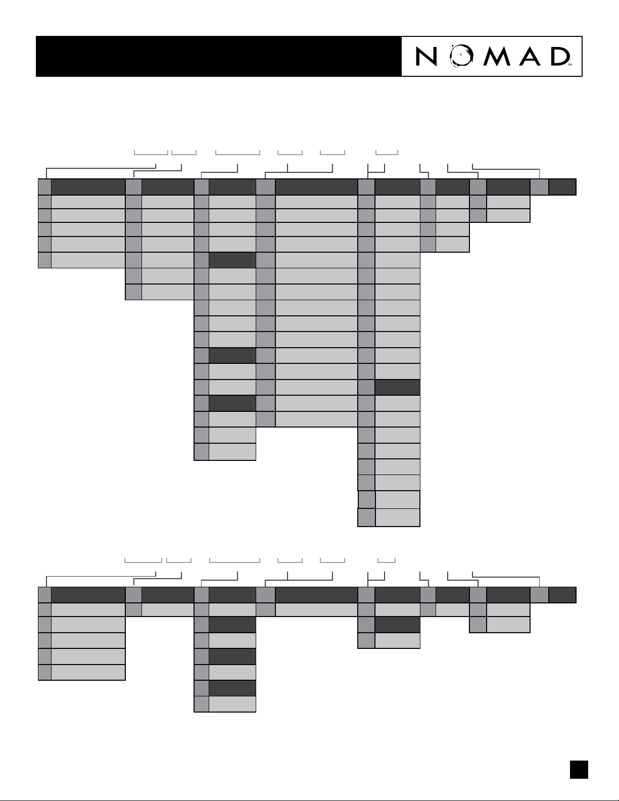
PUMP DESIGNATION SYSTEM
XXX XX / XXXX / XX / XX / XXX / X / X / X
1 2 3 4 5 6 7 8 9 10 11 12 13
1
Air Distribution System
N Nomad 07 07mm/.25” A Aluminum BN Buna - N/ Nitrile A Aluminum N NPT C Clamped
T Trans-Flo 15 15mm/.5” W Ductile ND Nordel/EPDM S Stainless Steel B BSP B Bolted
TG Gold 25 25mm/1” S Stainless Steel NE Neoprene BN Buna - N/Nitrile TC Tri-Clamp
PF Pwr-Flo 40 40mm/1.5” P Polypropylene TF PTFE (with Neoprene back-up) NE Neoprene
DF Dura-Flo 50 50mm/2”
2
Liquid Port Size
80 80mm/3” A Aluminum FG Hytrel® VT Viton
100 100mm/4” W Ductile SN Santoprene® SP Santoprene
3
Wetted Parts
4
Air Chambers
S Stainless Steel SNF Santoprene® - UFI FG Hytrel
W Mild Steel TFF PTFE - UFI P Polypropylene
P Polypropylene TGN Garlock® - NEO BACKED K Kynar
5
Center Block
A Aluminum TGV Garlock® - Viton BACKED MTF Mild Steel
P Polypropylene PU Polyurethane
6
Air Valve
B Brass PUF Polyurethane UFI NE Neoprene
PAPolypropylene ND Nordel/EPDM
Aluminum
7,8
Diaphragms & Valve Balls
VT Viton/FKM ND Nordel/EPDM
TGE Garlock® - EPDM BACKED PU Polyurethane
FGF Hytrel UFI BN Buna - N/Nitrile
9
Valve Seats
10
O-Ring
VT Viton
TF PTFE
PU Polyurethane
11
Fittings
FL Flanged
12
Connections 13 ATEX
SN Santoprene
PTV Viton Encap.
NTG 50 / AAAB / TF / TF / ATF / N / C / X
1 2 3 4 5 6 7 8 9 10 11 12 13
1
Air Distribution System
N Nomad 50 50mm/2” A Aluminum TF PTFE (with Buna back-up) A Aluminum N NPT C Clamped
T Trans-Flo
TG Gold A Aluminum TF PTFE
PF Pwr-Flo
DF Dura-Flo A Aluminum
2
Liquid Port Size
3
Wetted Parts
4
Air Chambers
5
Center Block
6
Air Valve
B Brass
7,8
Diaphragms & Valve Balls
9
10
Valve Seats
O-Ring
11
Fittings
12
Connections 13 ATEX
2
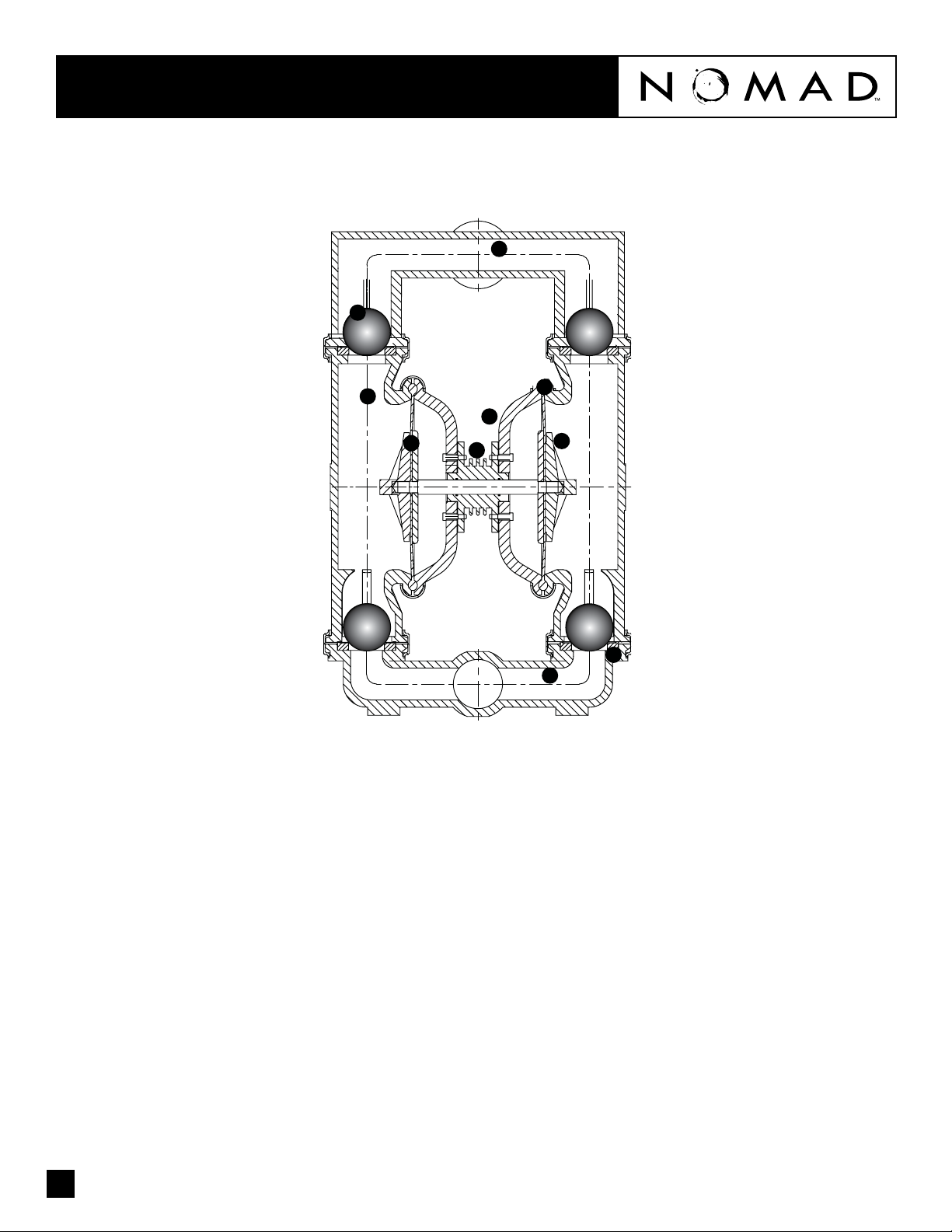
NTG40 How It Works - Pump™
The NOMAD diaphragm pump is an air-operated, positive displacement, self-priming pump. These drawings show ow pattern through the pump
upon its initial stroke. It is assumed the pump has no uid in it prior to its initial stroke.
7
5
1. Air Chamber
The air chamber is the chamber that houses
the air which powers the diaphragms.
2. Air Distribution System
The air distribution system is the heart of
the pump. The air distribution system is the
mechanism that shifts the pump in order to
create suction and discharge strokes.
3. Lock Nut (Outer Diaphragm Piston)
The outer diaphragm pistons provide a
means to connect the diaphragms to the
reciprocating common shaft and to seal the
liquid side from the air side of the diaphragm.
8
1
4
2
9
3
10
5. Check Valve Ball
NOMAD air-operated pumps use suction and
discharge check valves to produce directional
ow of process uid in the liquid chamber.
The check valve balls seal and release on the
check valve seats allowing for discharge and
suction of process uid to occur.
6. Check Valve Seat
The removable seats provide the ball valves a
site to check.
7. Discharge Manifold
Process uid exits the pump from the
discharge port located on the discharge
manifold at the top of the pump.
6
9. Diaphragm
The diaphragm membrane provides for
separation of the process uid and the
compressed air power source. To perform
adequately, diaphragms should be of
sufcient thickness and of appropriate
material to prevent degradation or permeation
in specic process uid applications. NOMAD
offers a variety of diaphragm materials for
your specic application requirements.
10. Inlet Manifold
Process uid enters the pump from the intake
port located on the inlet manifold at the
bottom of the pump.
4. Holding plate (Inner Diaphragm Piston)
The inner piston is located on the air side of
the pump and does not come into contact
with the process uid.
3
8. Liquid Chamber
The liquid chamber is lled with the process
uid during the suction stroke and is emptied
during the discharge stroke. It is separated
from the compressed air by the diaphragms.
 Loading...