

Page 1
PAMS Technical Documentation
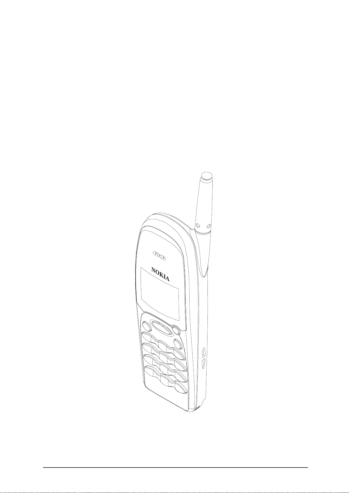
THF–13L Series Transceivers
TRANSCEIVER THF-13L
(For Croatia)
Issue 1 08/99 Nokia Mobile Phones Ltd.
Page 2
THF–13L
Variants
PAMS Technical Documentation
AMENDMENT RECORD SHEET
Amendment
Number
Date Inserted By Comments
08/99 Issue 1
Page 2
Nokia Mobile Phones Ltd.
Issue 1 08/99
Page 3

PAMS Technical Documentation
CONTENTS
Introduction 1 – 4. . . . . . . . . . . . . . . . . . . . . . . . . . . . . . . . . . . . . . . . . . . .
Functional Description 1 – 4. . . . . . . . . . . . . . . . . . . . . . . . . . . . . .
Modules 1 – 4. . . . . . . . . . . . . . . . . . . . . . . . . . . . . . . . . . . . . . . . . . . . .
RF Characteristics 1 – 4. . . . . . . . . . . . . . . . . . . . . . . . . . . . . . . . . . . .
Exploded View of THF–13L 1 – 5. . . . . . . . . . . . . . . . . . . . . . . . . . . .
Assembly Parts of THF–13L 1 – 6. . . . . . . . . . . . . . . . . . . . . . . . . . .
Parts list of NH1L SMD VARIATION MODULE 1 – 7. . . . . . . . . . . . .
THF–13L
Variants
Page No
Issue 1 08/99
Nokia Mobile Phones Ltd.
Page 3
Page 4

THF–13L
Variants
Introduction
The appendix comprises an exploded view of the THF–13L variant (including a list of assembly parts) plus component parts lists covering the
system module and the display module.
Functional Description
The transceiver electronics consist of UI module PCB and RF/system PCB.
UI module is connected to system module with a connector. System and rf
submodules are interconnected with PCB wiring. Unit can be connected to
accessories with a bottom system connector, which includes charging and
accessory control.
RF block is designed for a hand portable phone, which operates in NMT450
systems. Purpose of the RF module is to receive and demodulate radio frequency signal from the base station and to transmit a modulated RF signal
to the base station.
PAMS Technical Documentation
Modules
Transceiver THF–13L 0503232
• system module NH2 0201499
• software module 0240880
• User Interface module NU1 0201258
• mechanics MTHF13 0262100
Swap package 0063358
RF Characteristics
Characteristic Value / Comments
RX Frequency range 411.675...415.850 MHz
TX Frequency range 421.675...425.850 MHz
Channel spacing 25 kHz
Number of channels 168 (1...168)
TX Frequency deviation ≤± 4.7 kHz (± 5 kHz with 4 kHz supervisory sig-
nal)
FFSK deviation
• 1200 Hz (”1” frequency) ± 2800 Hz
• 1800 Hz (”0” frequency) ± 4200 Hz
Page 4
Nokia Mobile Phones Ltd.
Issue 1 08/99
Page 5

PAMS Technical Documentation
Exploded View of THF-13L
THF–13L
Variants
10
9
M1
13
7
14
6
M2
5
4
1
2
8
11
14
12
Issue 1 08/99
3
Nokia Mobile Phones Ltd.
Page 5
Page 6

THF–13L
Variants
PAMS Technical Documentation
Assembly Parts of THF-13L
ITEM Q’TY CODE DESCRIPTION VALUE, TYPE
1 9490097 A–cover DMS02119
2 9458003 Window assembly DMC02479
3 9794023 Keymat module DMC02477
4 5140580 Speaker
5 0200921 LCD module GD40
6 9470079 Insulation plate DMD04330
7 9450031 Chassis DMD04337
8 5140101 Microphone + mic.boot DMC00955
9480327 Support tape DMD02590
9 9790363 Side key assembly DMD04459
10 9456396 B–cover DMC01944
11 0660185 Antenna DMD04396
12 9380529 Type label 4D25502
13 1 6190023 Screw M1.6x4 T6 FeZn cl DMD02852
14 5 6190013 Screw M1.6x7 T6 FeZn cl DMD01749
M1 0201499 NH2 system module THF–13
M2 0201258 NH1 UIF THF–13
Page 6
Nokia Mobile Phones Ltd.
Issue 1 08/99
Page 7

THF–13L
PAMS Technical Documentation
Variants
Parts list of NH2 SMD VARIATION MODULE
(EDMS Issue1.6 ) Code: 0201274
ITEM CODE DESCRIPTION VALUE TYPE
R356 1430690 Chip jumper 0402
R420 1430788 Chip resistor 22 k 5 % 0.063 W 0402
R421 1430774 Chip resistor 6.8 k 5 % 0.063 W 0402
R422 1430792 Chip resistor 33 k 5 % 0.063 W 0402
R423 1430804 Chip resistor 100 k 5 % 0.063 W 0402
R433 1430788 Chip resistor 22 k 5 % 0.063 W 0402
R434 1430774 Chip resistor 6.8 k 5 % 0.063 W 0402
R435 1430792 Chip resistor 33 k 5 % 0.063 W 0402
R436 1430804 Chip resistor 100 k 5 % 0.063 W 0402
R442 1430710 Chip resistor 22 5 % 0.063 W 0402
R443 1430722 Chip resistor 68 5 % 0.063 W 0402
R444 1430710 Chip resistor 22 5 % 0.063 W 0402
C301 2320536 Ceramic cap. 10 p 5 % 50 V 0402
C302 2320564 Ceramic cap. 150 p 5 % 50 V 0402
C312 2320560 Ceramic cap. 100 p 5 % 50 V 0402
C351 2320536 Ceramic cap. 10 p 5 % 50 V 0402
C420 2320596 Ceramic cap. 3.3 n 5 % 50 V 0402
C421 2320779 Ceramic cap. 100 n 10 % 16 V 0603
C422 2320618 Ceramic cap. 4.7 n 5 % 25 V 0402
C423 2320596 Ceramic cap. 3.3 n 5 % 50 V 0402
C424 2320584 Ceramic cap. 1.0 n 5 % 50 V 0402
C435 2320596 Ceramic cap. 3.3 n 5 % 50 V 0402
C436 2320779 Ceramic cap. 100 n 10 % 16 V 0603
C437 2320618 Ceramic cap. 4.7 n 5 % 25 V 0402
C438 2320596 Ceramic cap. 3.3 n 5 % 50 V 0402
C439 2320584 Ceramic cap. 1.0 n 5 % 50 V 0402
C441 2320560 Ceramic cap. 100 p 5 % 50 V 0402
C444 2320602 Ceramic cap. 4.7 p 0.25 % 50 V 0402
C445 2320584 Ceramic cap. 1.0 n 5 % 50 V 0402
C662 2320550 Ceramic cap. 39 p 5 % 50 V 0402
C663 2320546 Ceramic cap. 27 p 5 % 50 V 0402
C664 2320550 Ceramic cap. 39 p 5 % 50 V 0402
C666 2320602 Ceramic cap. 4.7 p 0.25 % 50 V 0402
C690 2320584 Ceramic cap. 1.0 n 5 % 50 V 0402
L301 3643013 Chip coil 27 n 5 % Q=40/250 MHz
0805
L310 3643003 Chip coil 12 n 5 % Q=30/250 MHz
0805
L311 3643013 Chip coil 27 n 5 % Q=40/250 MHz
0805
L441 3641522 Chip coil 6 n 20 % Q=50/250 MHz
0805
Issue 1 08/99
Nokia Mobile Phones Ltd.
Page 7
Page 8

THF–13L
Variants
L652 3645165 Chip coil 3 n 10 % Q=10/100 MHz
0603
G420 4350191 Vco 375–385mhz 2.8v 12ma rx nmt
G430 4350193 Vco 410–420mhz 2.8v 15ma tx nmt
Z330 4511007 Saw filter 423.8+–2.1 M 5.2x5.2
Z640 4512111 Dupl 411.7–415.9/421.7–425.9mhz
PAMS Technical Documentation
Page 8
Nokia Mobile Phones Ltd.
Issue 1 08/99
 Loading...