

Page 1

PAMS Technical Documentation
TFF-3 WLL Terminal
Service Software
Instructions
and
Subdata User Guide
Issue 1 08/99 Nokia Mobile Phones Ltd.
Page 2
TFF-3
Service Software Instructions
AMENDMENT RECORD SHEET
PAMS Technical Documentation
Amendment
Number
Date Inserted By Comments
08/99 OJuntune Original
Page 2
Nokia Mobile Phones Ltd.
Issue 1 08/99
Page 3

PAMS Technical Documentation
Service Software Instructions
CONTENTS
Service Software 5. . . . . . . . . . . . . . . . . . . . . . . . . . . . . . . . . . . . . . . .
General 5. . . . . . . . . . . . . . . . . . . . . . . . . . . . . . . . . . . . . . . . . . . . .
Minimum Required Servicing Equipment 5. . . . . . . . . . . . . .
Installation 6. . . . . . . . . . . . . . . . . . . . . . . . . . . . . . . . . . . . . . . .
Start Up Procedure 7. . . . . . . . . . . . . . . . . . . . . . . . . . . . . . . . . . .
Introduction to Service Software Package User Interface 8. . . . .
Service Software/Hardware Environment 8. . . . . . . . . . . . . . . .
Service Software Environment 8. . . . . . . . . . . . . . . . . . . . . . . . .
Service Software Executables 9. . . . . . . . . . . . . . . . . . . . . . .
Command Line Parameters 9. . . . . . . . . . . . . . . . . . . . . . . . .
Common Properties of the User Interface 10. . . . . . . . . . . . . . . . . .
TFF-3
Page No
Login Dialog 10. . . . . . . . . . . . . . . . . . . . . . . . . . . . . . . . . . . . . . . . .
Main Window 12. . . . . . . . . . . . . . . . . . . . . . . . . . . . . . . . . . . . . . . .
Menu Bar 14. . . . . . . . . . . . . . . . . . . . . . . . . . . . . . . . . . . . . . . . . . . .
Product 15. . . . . . . . . . . . . . . . . . . . . . . . . . . . . . . . . . . . . . . . . . .
Configure 15. . . . . . . . . . . . . . . . . . . . . . . . . . . . . . . . . . . . . . . . .
Tuning 16. . . . . . . . . . . . . . . . . . . . . . . . . . . . . . . . . . . . . . . . . . . .
Testing 16. . . . . . . . . . . . . . . . . . . . . . . . . . . . . . . . . . . . . . . . . . . .
Specific 16. . . . . . . . . . . . . . . . . . . . . . . . . . . . . . . . . . . . . . . . . . .
Dealer 17. . . . . . . . . . . . . . . . . . . . . . . . . . . . . . . . . . . . . . . . . . . .
View 18. . . . . . . . . . . . . . . . . . . . . . . . . . . . . . . . . . . . . . . . . . . . . .
Help 18. . . . . . . . . . . . . . . . . . . . . . . . . . . . . . . . . . . . . . . . . . . . . .
Mouse Cursors 19. . . . . . . . . . . . . . . . . . . . . . . . . . . . . . . . . . . . . . .
Reserved Keys 19. . . . . . . . . . . . . . . . . . . . . . . . . . . . . . . . . . . . . . .
Short Cut Function Keys 19. . . . . . . . . . . . . . . . . . . . . . . . . . . .
Alt Hot Keys 19. . . . . . . . . . . . . . . . . . . . . . . . . . . . . . . . . . . . . . .
Ctrl Hot Keys 19. . . . . . . . . . . . . . . . . . . . . . . . . . . . . . . . . . . . . .
Shift Hot Keys 20. . . . . . . . . . . . . . . . . . . . . . . . . . . . . . . . . . . . .
Key Strokes 20. . . . . . . . . . . . . . . . . . . . . . . . . . . . . . . . . . . . . . .
Help Functions 21. . . . . . . . . . . . . . . . . . . . . . . . . . . . . . . . . . . . .
Dialog boxes 21. . . . . . . . . . . . . . . . . . . . . . . . . . . . . . . . . . . . . . . . .
Common Dialog boxes 22. . . . . . . . . . . . . . . . . . . . . . . . . . . . . .
Note Message Box 22. . . . . . . . . . . . . . . . . . . . . . . . . . . . . . . . .
Query Message Box 22. . . . . . . . . . . . . . . . . . . . . . . . . . . . . . . .
Error Message Box 23. . . . . . . . . . . . . . . . . . . . . . . . . . . . . . . . .
Custom Dialog boxes 23. . . . . . . . . . . . . . . . . . . . . . . . . . . . . . . . .
Buttons 23. . . . . . . . . . . . . . . . . . . . . . . . . . . . . . . . . . . . . . . . . . .
Reporting Status 24. . . . . . . . . . . . . . . . . . . . . . . . . . . . . . . . . . .
TFF-3 Specific Features 25. . . . . . . . . . . . . . . . . . . . . . . . . . . . . . . . .
Menu bar 25. . . . . . . . . . . . . . . . . . . . . . . . . . . . . . . . . . . . . . . . . . . .
Issue 1 08/99
Nokia Mobile Phones Ltd.
Page 3
Page 4

TFF-3
Service Software Instructions
Product Menu 25. . . . . . . . . . . . . . . . . . . . . . . . . . . . . . . . . . . . .
New command 25. . . . . . . . . . . . . . . . . . . . . . . . . . . . . . . . . .
Open...command 26. . . . . . . . . . . . . . . . . . . . . . . . . . . . . . . .
Close...command 26. . . . . . . . . . . . . . . . . . . . . . . . . . . . . . . .
Initialize...command 26. . . . . . . . . . . . . . . . . . . . . . . . . . . . . .
Faultlog 27. . . . . . . . . . . . . . . . . . . . . . . . . . . . . . . . . . . . . . . .
Exit...command 27. . . . . . . . . . . . . . . . . . . . . . . . . . . . . . . . . .
Configure Menu 28. . . . . . . . . . . . . . . . . . . . . . . . . . . . . . . . . . . .
Options... command 28. . . . . . . . . . . . . . . . . . . . . . . . . . . . . .
Directories... command 29. . . . . . . . . . . . . . . . . . . . . . . . . . .
Faultlog... command 30. . . . . . . . . . . . . . . . . . . . . . . . . . . . .
RF Controls...command 31. . . . . . . . . . . . . . . . . . . . . . . . . .
Tuning Menu 32. . . . . . . . . . . . . . . . . . . . . . . . . . . . . . . . . . . . . . . . .
Initialize Local Mode 32. . . . . . . . . . . . . . . . . . . . . . . . . . . . .
AFC Frequency 33. . . . . . . . . . . . . . . . . . . . . . . . . . . . . . . . . .
AFC Frequency Limits 34. . . . . . . . . . . . . . . . . . . . . . . . . . . .
RSSI and AGC 36. . . . . . . . . . . . . . . . . . . . . . . . . . . . . . . . . .
Deviation Tuning 38. . . . . . . . . . . . . . . . . . . . . . . . . . . . . . . . .
TX Output Power 40. . . . . . . . . . . . . . . . . . . . . . . . . . . . . . . .
Show Tuning Values 41. . . . . . . . . . . . . . . . . . . . . . . . . . . . .
Testing Menu 42. . . . . . . . . . . . . . . . . . . . . . . . . . . . . . . . . . . . . .
Basic Settings 43. . . . . . . . . . . . . . . . . . . . . . . . . . . . . . . . . . .
ADC Readings 45. . . . . . . . . . . . . . . . . . . . . . . . . . . . . . . . . .
Audio Controls 46. . . . . . . . . . . . . . . . . . . . . . . . . . . . . . . . . .
Special Settings 47. . . . . . . . . . . . . . . . . . . . . . . . . . . . . . . . .
FFSK Data Sending Control 48. . . . . . . . . . . . . . . . . . . . . . .
Single Tone and DTMF Control 50. . . . . . . . . . . . . . . . . . . .
Field Test Display 50. . . . . . . . . . . . . . . . . . . . . . . . . . . . . . . .
Specific Menu 51. . . . . . . . . . . . . . . . . . . . . . . . . . . . . . . . . . . . .
Call Control 52. . . . . . . . . . . . . . . . . . . . . . . . . . . . . . . . . . . . .
Automatic Area Code 53. . . . . . . . . . . . . . . . . . . . . . . . . . . . .
Calling Line Identification 55. . . . . . . . . . . . . . . . . . . . . . . . .
Charge Advice Information 58. . . . . . . . . . . . . . . . . . . . . . . .
Pulse Dialing Settings 59. . . . . . . . . . . . . . . . . . . . . . . . . . . .
Immobilizer 60. . . . . . . . . . . . . . . . . . . . . . . . . . . . . . . . . . . . .
Tariff Table 61. . . . . . . . . . . . . . . . . . . . . . . . . . . . . . . . . . . . . .
Dealer Menu 63. . . . . . . . . . . . . . . . . . . . . . . . . . . . . . . . . . . . . .
Subscriber Data 63. . . . . . . . . . . . . . . . . . . . . . . . . . . . . . . . .
Traffic Areas 66. . . . . . . . . . . . . . . . . . . . . . . . . . . . . . . . . . . .
Warranty Information 67. . . . . . . . . . . . . . . . . . . . . . . . . . . . .
Country Codes 68. . . . . . . . . . . . . . . . . . . . . . . . . . . . . . . . . .
View Menu 70. . . . . . . . . . . . . . . . . . . . . . . . . . . . . . . . . . . . . . . .
Phone Identity 70. . . . . . . . . . . . . . . . . . . . . . . . . . . . . . . . . . .
Help Menu 71. . . . . . . . . . . . . . . . . . . . . . . . . . . . . . . . . . . . . . . .
Appendix 1, Vocabulary 72. . . . . . . . . . . . . . . . . . . . . . . . . . . . .
PAMS Technical Documentation
Page 4
Nokia Mobile Phones Ltd.
Issue 1 08/99
Page 5

PAMS Technical Documentation
Service Software
General
The TFF-3 Service Software can be used to control the phone according
to the user’s requirements merely by entering commands via the key-
board / mouse of a PC connected to the phone.
Minimum Required Servicing Equipment
–Computer: Intel 386/33 MHz or compatible with one unused serial port
(COM1 or COM2*), one parallel port (LPT1), hard disk recommended.
–Operating System: DOS Version 5 & Microsoft Windows 3.11 or later
–Display: VGA based display
–Service Software program: for 3.5” disk (product code: 0774115)
TFF-3
Service Software Instructions
–Software Protection Key PKD–1 (product code 0750018)
–M2BUS interface cable DAU–9S (product code 0730108)
*)
Note:
A number of PC’s of an older generation use the Intel, National Semicon-
ductor, or United Microelectronics IC 8250 as the serial port UART. This is
a comparatively inefficient circuit for current purposes and does not nec-
essarily support the M2BUS adapter at 9600 baud. The newer UART’s
NS16450 and NS16550AF of National Semiconductor offer solutions for
these problems.
Issue 1 08/99
Nokia Mobile Phones Ltd.
Page 5
Page 6
TFF-3
Service Software Instructions
Installation
Caution: Ensure that you have switched off the PC and the printer be-
fore making connections !
Caution: Do not connect the PKD–1 to the serial port. This could damage
the PKD–1 !
The software controls the phone via a separate adapter connected to the
serial port of the PC and to the telephone’s M2BUS (RS–232 D25/D9
adapter and PC Link adapter DAU–2T). Modular Cable XCM–1 is also
needed between adapters and TFF3.
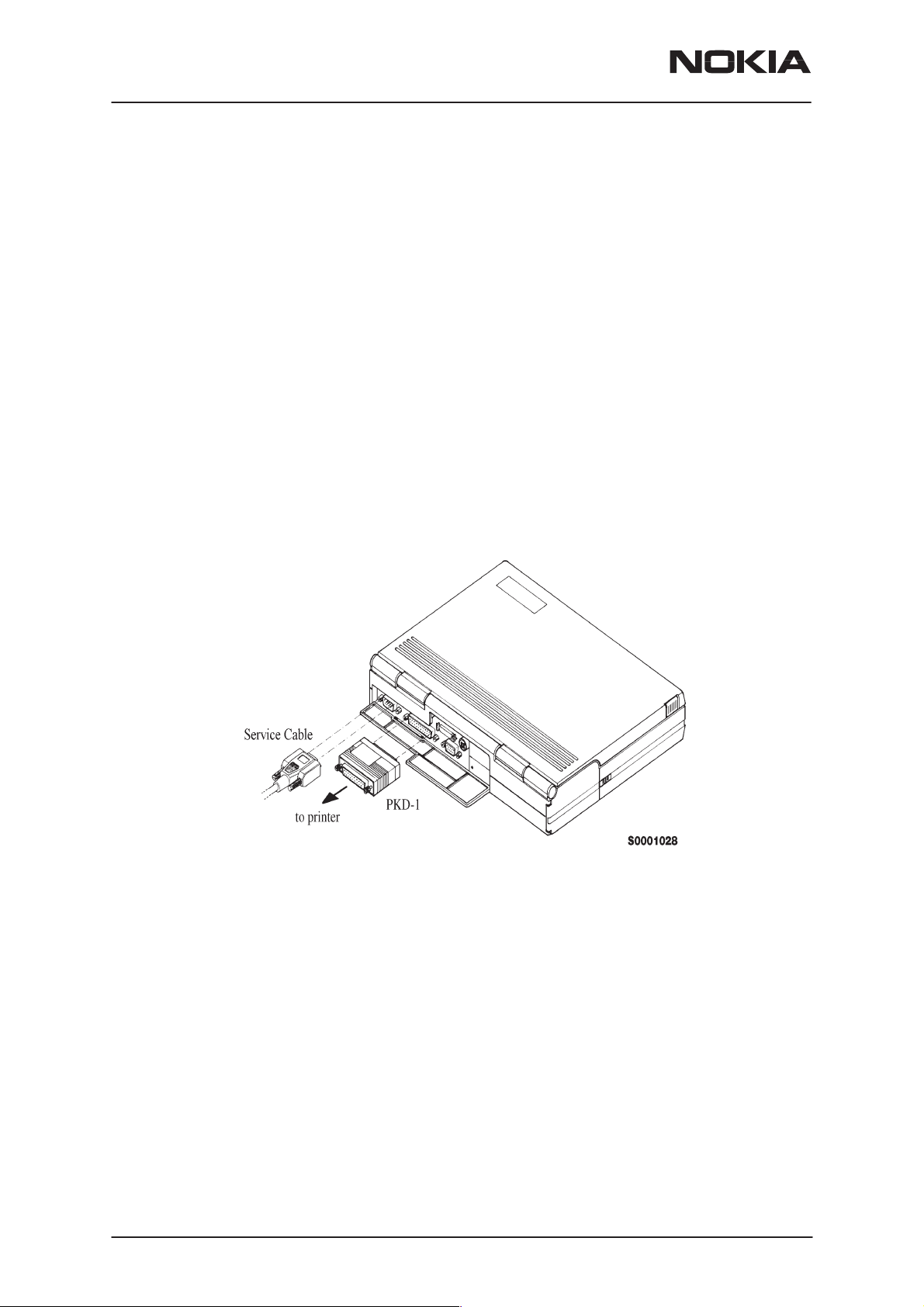
Attach the protection key PKD–1 to parallel port one (25–pin female
D–connector) of the PC. When connecting the PKD–1 to the parallel port
be sure that you insert the PC end of the PKD–1 to the PC (male side). If
you use a printer on parallel port one, place the PKD–1 between the PC
and your printer cable.
The PKD–1 should not effect devices working with it. If some errors occur
(errors in printing are possible) please try printing without the PKD–1.
PAMS Technical Documentation
Page 6
Nokia Mobile Phones Ltd.
Issue 1 08/99
Page 7

PAMS Technical Documentation
Start Up Procedure
Start the phone by pressing the power–on button of the handset. Switch
PC power on. Make sure that WinTesla and dongle drivers are already
installed on your PC. If not, install WinTesla and dongle drivers first.
To installing software, proceed as follows:
1. Insert Service Software disk into drive A of your PC
TFF-3
Service Software Instructions
2. Start Windows: type
3. Start Installing program: select
4. Follow Installation Software instructions. The installation program will
search automatically WinTesla directory.
5. After installation start WinTesla by clicking the WinTesla icon. WinTesla
can also be started with command WINTESLA.EXE.
6. Choose menu item Configure–Options and configure COM port, auto-
matic rescan etc.
7. The buses must be configured too. Choose menu item Configure–
Buses.
8. Choose the COM port from the first combobox. Select the hardware
type from the second combobox, DAU for mBus should be selected. Me-
dia is selected from the third combobox. Choose mBus.
9. Press Add–button and accept settings by pressing OK–button.
10. If you want to remove bus configuration, press Remove–button and
do item 9 again.
WIN
and press
File –> Run
Manager menu, then type
and press OK button
Enter
from Program
A:INSTALL
Issue 1 08/99
Nokia Mobile Phones Ltd.
Page 7
Page 8
TFF-3
Service Software Instructions
PAMS Technical Documentation
Introduction to Service Software Package User Interface
This chapter gives a brief description of the Service Software properties.
Service Software/Hardware Environment
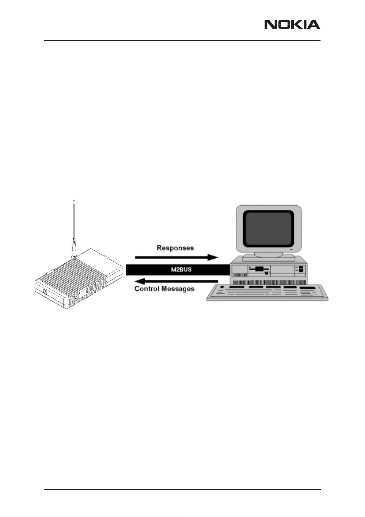
To run the Service Software, a parallel port software protection device
(PKD–1) has to be connected. The user can use the Service Software
functions for testing all TFF3 terminal types. The functions send mes-
sages from the PC to the phone, receives results and shows them on the
PC display.
Service PC environment is described below:
The recommended minimum hardware standard to run the Service Soft-
ware package is any computer which is 386 33Mhz or greater with at
least 4 MB of memory and VGA type display (640x480). This assumes
that only the Service Software package is active, i.e. other Windows pack-
ages are not running in the background.
Note: if the Service Software is to be run on a laptop, the power saving
feature MUST be switched off.
Service Software Environment
Service Software user interface is intended for Microsoft Windows 3.11
environment running in enhanced mode. For those who are familiar with
Windows environment this application will be easy to use. Detailed in-
formation about Windows and application usage can be found from Ref
3– Microsoft Windows Version 3.11 Users Guide chapter one (Windows
Basics) and chapter two (Application Basics).
As an ordinary Windows application, the main idea in the user interface is
that selections are made with menus, push buttons and shortcut keys.
Page 8
Nokia Mobile Phones Ltd.
Issue 1 08/99
Page 9

PAMS Technical Documentation
Selections can be done by using keyboard and/or mouse. When mes-
sages from phone are received, they cause display updating in special
display windows. There is always a status bar displayed at the bottom of
the main window which contains information about current actions.
Service Software Executables
Only one executable is needed – WinTesla.
The service software uses two DLL’s:
– Functionality DLL is TFF3.DLL
– User Interface DLL is TFF3EN.DLL
Command Line Parameters
There are NO command line parameters.
TFF-3
Service Software Instructions
Issue 1 08/99
Nokia Mobile Phones Ltd.
Page 9
Page 10
TFF-3
Service Software Instructions
PAMS Technical Documentation
Common Properties of the User Interface
This chapter describes how the User Interface CLF must appear to the
user.
The User Interface MUST be capable of being driven without the use of a
mouse, as the service engineer rarely has space on the bench to use a
mouse.
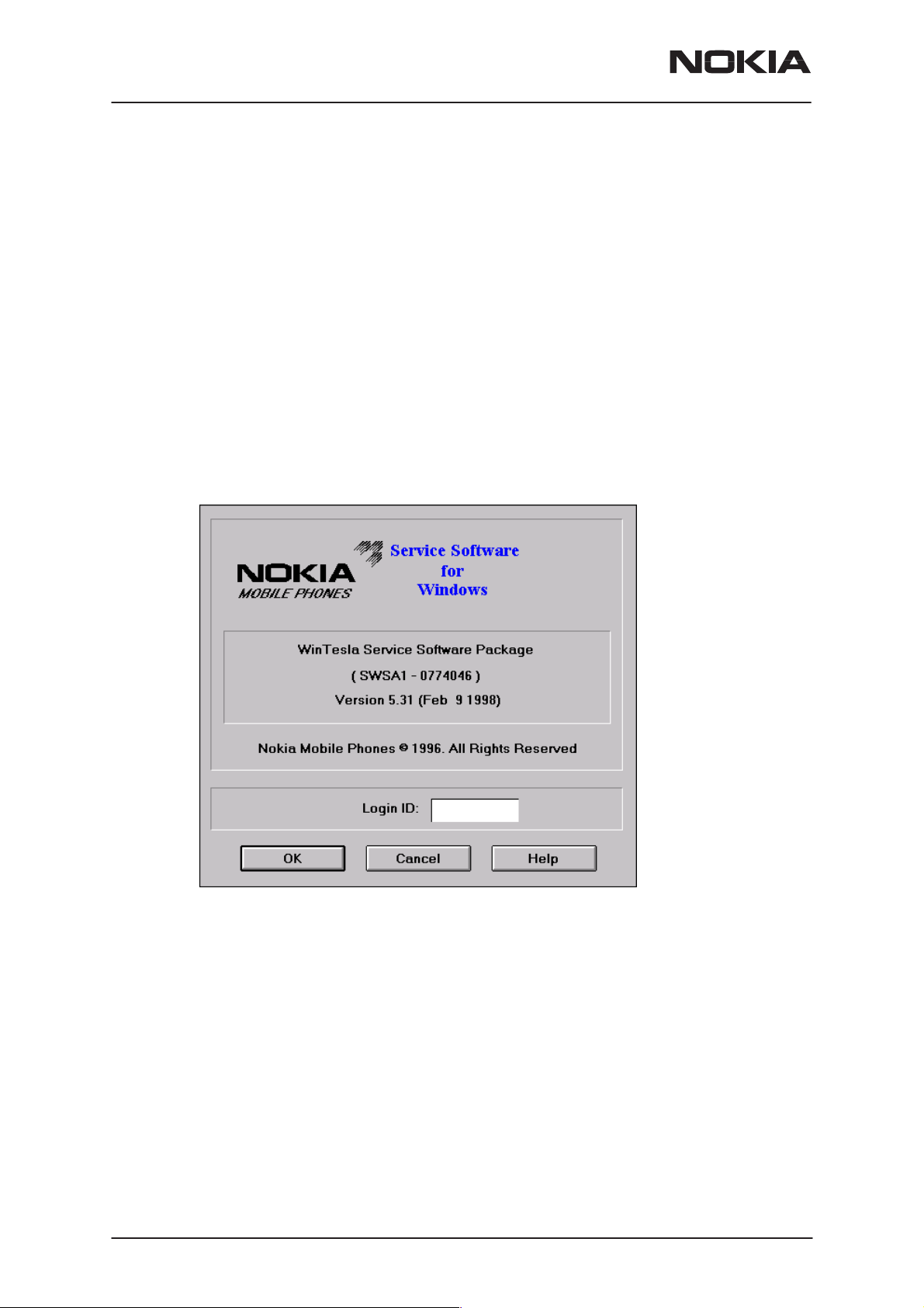
Login Dialog
When the Service Software application is invoked, by checking on the
Service Software icon, the Login dialog box will be displayed on the
screen.
Page 10
Nokia logo and application name bitmap (–)
Displays Nokia logo and name of the application.
Application version static text (–)
Contains the name and version of the application.
Copyright notice static text (–)
Copyright is informed as: “Nokia Mobile Phones (c) 1996. All
Rights Reserved”.
Login Box edit box (–)
The user Login ID edit box, where the user enters his faultlog
user name.
Nokia Mobile Phones Ltd.
Issue 1 08/99
Page 11

PAMS Technical Documentation
OK button (default key)
The user name is stored in memory and the dialog box is
closed. When the dialog box is closed, the application starts.
Cancel button (ESC)
The Dialog box is closed and application is started, but the
Faultlog feature is disabled.
Help button (F1)
Activates the Windows Help application and displays context
sensitive Help.
TFF-3
Service Software Instructions
Issue 1 08/99
Nokia Mobile Phones Ltd.
Page 11
Page 12
TFF-3
Service Software Instructions
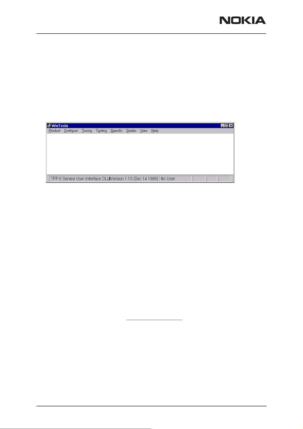
Main Window
PAMS Technical Documentation
The application supports a
the service software interface will present a
appearance.
(SDI)
Note: MDI is to allow for future expansion, e.g. R&D features.
The
title bar
A title bar contains the following elements:
– • Application Control–menu button
– • Maximize button
– • Minimize button
is located at the top of the window.
Multiple Document Interface (MDI).
Single Document Interface
However,
Menu bar
Status bar
– • Name of the application
– • Restore button
The properties of these elements and their usage is described in Ref 3–
Microsoft Windows Version 3.1 Users Guide chapter One (Windows Ba-
sics) and chapter Two (Application Basics).
menu bar
The
tions. The menu bar is a dynamic element and is dependent on the
dongle type fitted, and whether a phone is connected. Underlined charac-
ters in menu names and options indicates that the menu selection can be
done by pressing
by activating menu bar with
to highlight the desired menu. In that case, selection is done by pressing
Enter
.
Menus can also be selected by using the mouse as described in Ref
3–Microsoft Windows Version 3.11 Users Guide.
status bar
The
window. The status bar contains information about the menu selections
and events.
is below the title bar and contains all available menu selec-
Alt+ underlined character
Alt
– key ( or
is displayed at the bottom of the Service Software main
. Options can also be selected
F10
key ) and using arrow–keys
Page 12
Nokia Mobile Phones Ltd.
Issue 1 08/99
Page 13

PAMS Technical Documentation
The left area of the status bar describes the actions of menu items as the
user uses the arrow keys to navigate through menus.
The status bar texts are explained in detailed in each of command’s de-
scription.
The right areas of the status bar indicate which of the following keys are
latched down:
Indicator Description
USER Entered Login ID.
CAP The Caps Lock key is latched down.
NUM The Num Lock key is latched down.
SCRL The Scroll Lock key is latched down.
Tool bar
The
tool bar
this document.
is NOT defined and will not be implemented until specified by
TFF-3
Service Software Instructions
Issue 1 08/99
Nokia Mobile Phones Ltd.
Page 13
Page 14

TFF-3
Service Software Instructions
Menu Bar
The Service Software package will have two menu bar configurations.
The first, is an abbreviated version that contains the minimum number of
menus that allows package configurations when a phone is NOT con-
nected. The second is described below:
The menu bar MUST only contain the follow menus for the Service Soft-
ware package when a phone is connected:
roduct*
• P
• C
onfigure*
uning
• T
sting
• Te
• S
pecific
PAMS Technical Documentation
• D
ealer
iew
• V
elp* * – always displayed, even if no phone is connected.
• H
A menu is broken down into sections that are indicated with menu separators. Each sections identifies a logical difference from itself and other
sections, i.e. between transmitter and receiver. Any items that are required to be added to a menu lists will be added on the bottom of the appropriate menu section list. If a new item is to be added which is common
to two or more phone types, then that menu item will become a common
menu item.
The menu lists will use the Microsoft [...] symbol after an item name to indicate that selecting that item will NOT initiate an operation immediately,
i.e. a dialog box will be displayed for the user to select options or type in
data and press the OK button before the operation is performed.
Page 14
Nokia Mobile Phones Ltd.
Issue 1 08/99
Page 15
PAMS Technical Documentation
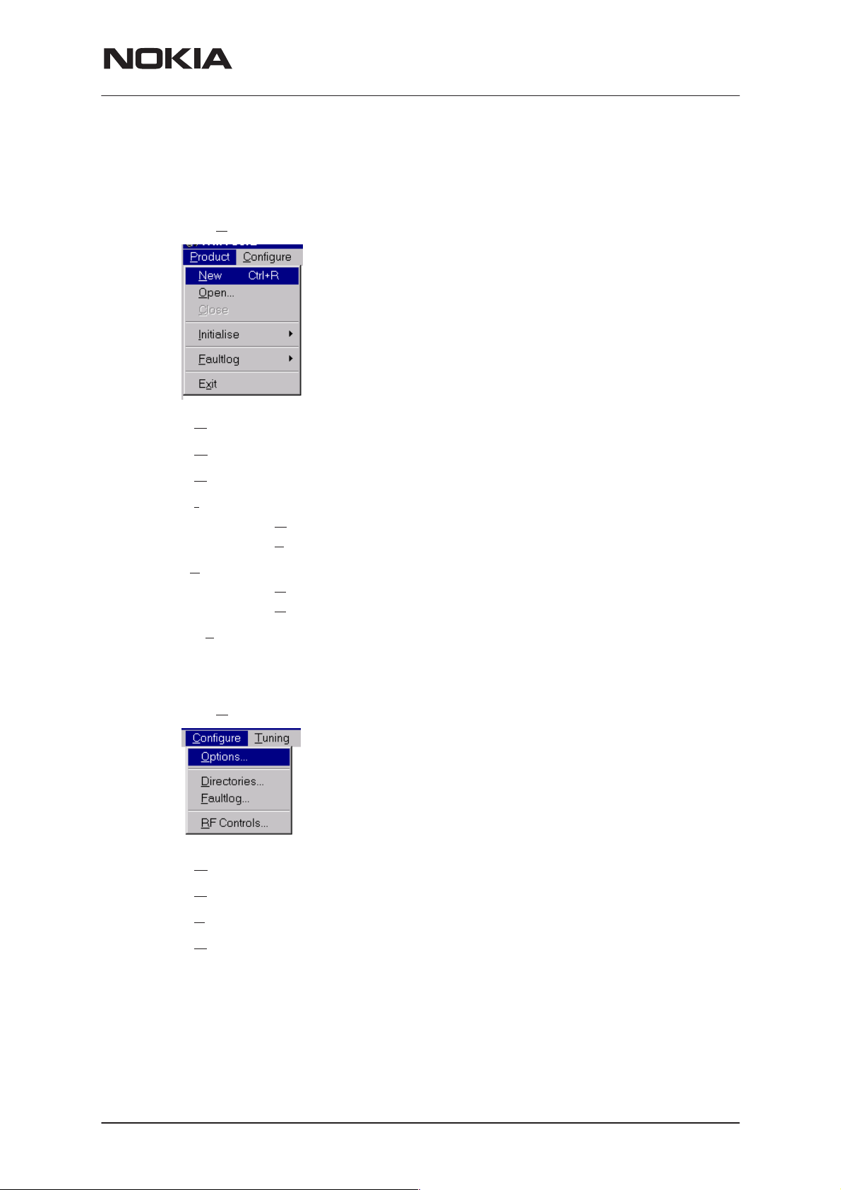
Product
The Product menu contains the following menu items:
• New Ctrl+R
pen...
• O
TFF-3
Service Software Instructions
• C
• I
•F
• Ex
Configure
The Configure menu contains the following menu items:
• Options...
lose
nitialize
ormal Mode F5
• N
• Local Mode Shift+F5
aultlog
ctivate Faultlog... F9
• A
• Edit Faultlog...
it Alt+F4
• D
• F
• R
Issue 1 08/99
irectories...
aultlog...
F Controls...
Nokia Mobile Phones Ltd.
Page 15
Page 16
TFF-3
Service Software Instructions
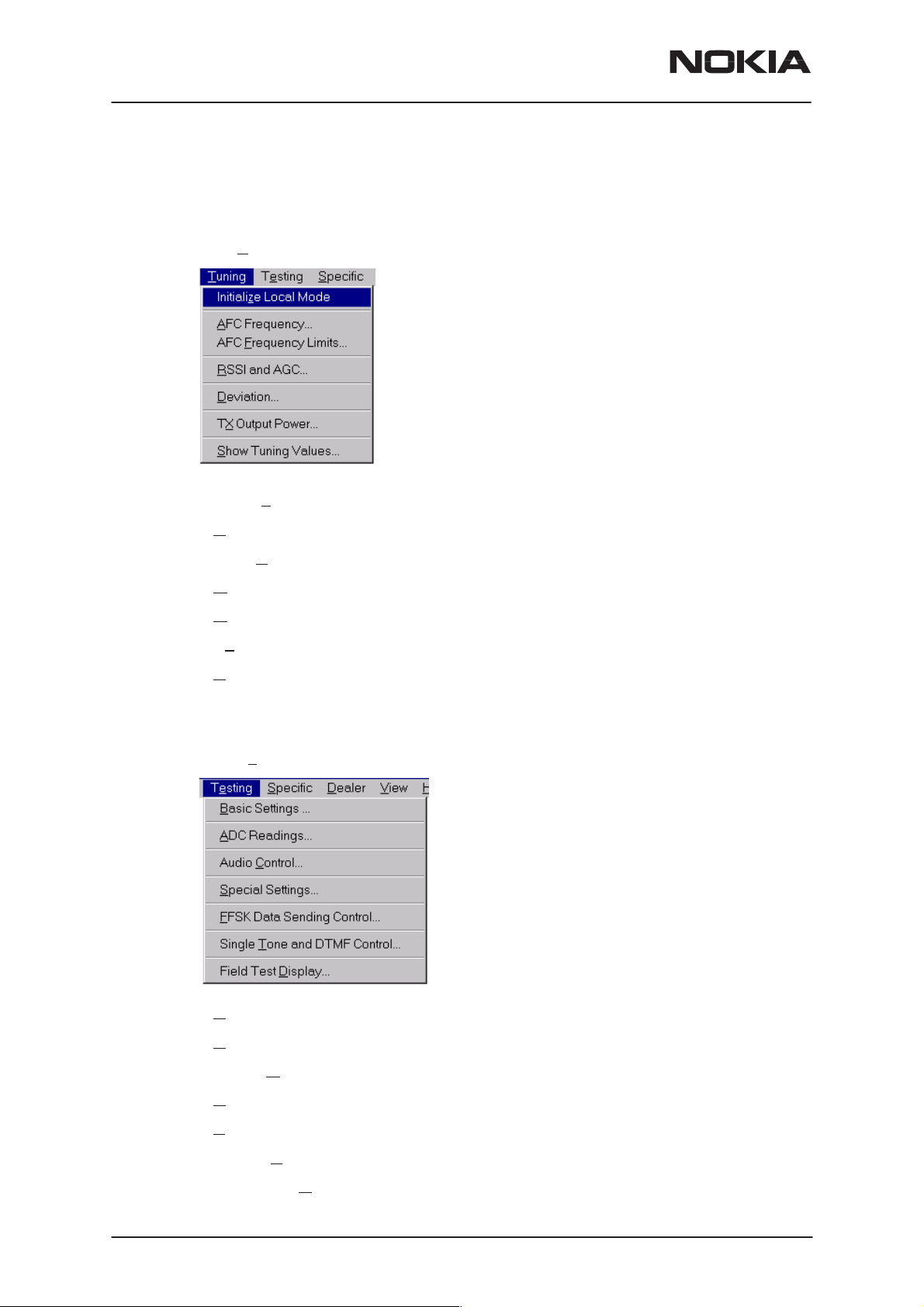
Tuning
The Tuning menu contains the following menu menu items:
• Initialize Local Mode
PAMS Technical Documentation
Testing
• A
FC Frequency...
• AFC F
• R
• D
• Tx
• S
The Testing menu contains the following menu items:
requency Limits...
SSI and AGC...
eviation...
Output Power...
how Tuning Values...
Page 16
• Basic Settings...
DC Readings...
• A
• Audio C
• S
pecial Settings...
FSK Data Sending Control...
• F
• Single T
• Field Test D
ontrol
one and DTMF Control...
isplay...
Nokia Mobile Phones Ltd.
Issue 1 08/99
Page 17
PAMS Technical Documentation
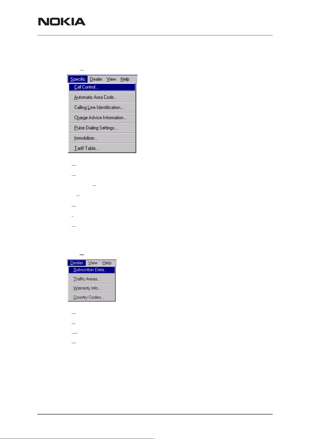
Specific
TFF-3
Service Software Instructions
The S
• Call Control...
• A
• Calling L
• Ch
• P
• I
pecific menu contains the following menu items:
utomatic Area Code...
ine Identification
arge Advice Information…
ulse Dialing Settings...
mmobilizer...
Dealer
• T
ariff table...
The Dealer menu contains the following menu items:
• Subscriber Data...
• T
raffic Areas...
arranty Info...
• W
• C
ountry codes...
Issue 1 08/99
Nokia Mobile Phones Ltd.
Page 17
Page 18
TFF-3
Service Software Instructions
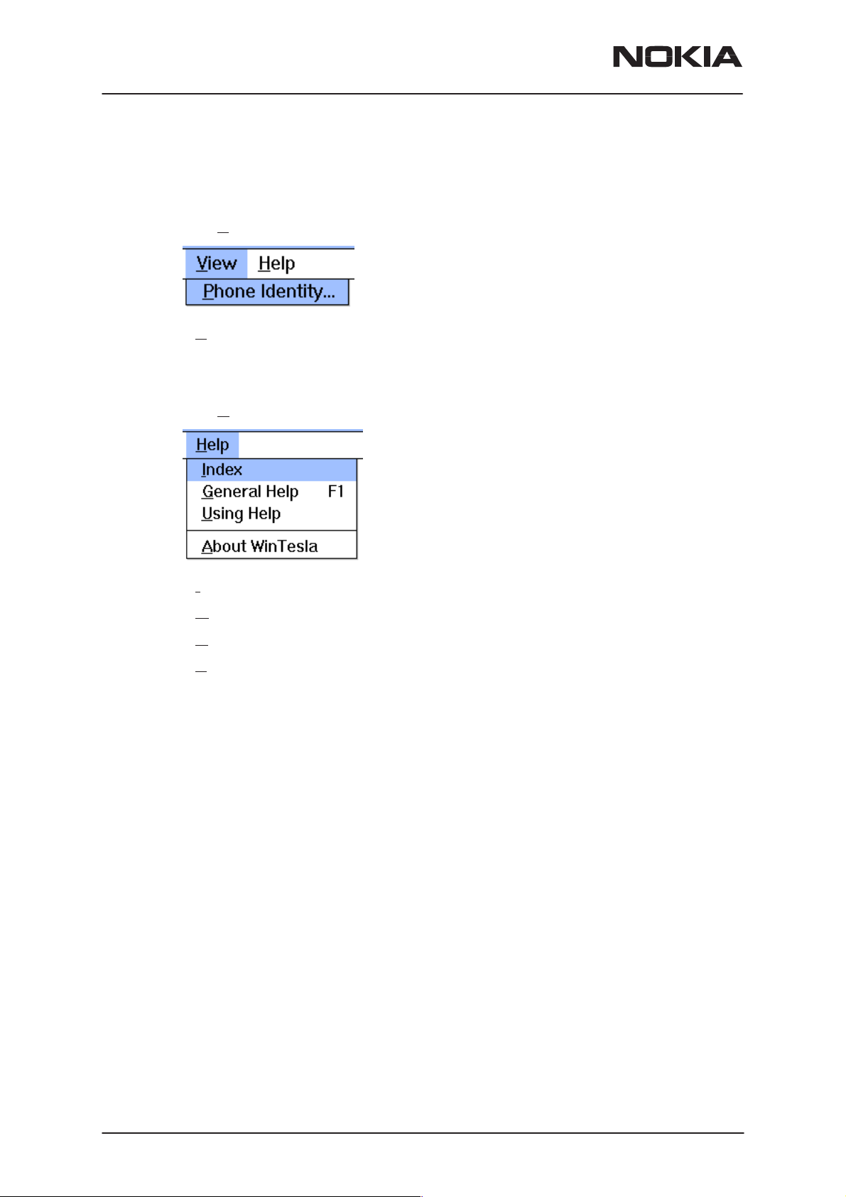
View
The View menu contains the following menu items:
• Phone Identity...
Help
The Help menu contains the following menu items:
PAMS Technical Documentation
• Index
eneral Help
• G
• U
sing Help
bout WinTesla
• A
Page 18
Nokia Mobile Phones Ltd.
Issue 1 08/99
Page 19

PAMS Technical Documentation
Mouse Cursors
The standard Windows pointer will be used as the mouse cursor.
During time consuming tasks e.g. communication to phone, an hour glass
will be shown informing the user that a task is in progress. The application
uses the hour glass cursor to inform user that the application has taken
the control and any actions from user will be ignored.
When a function is initiated, the hour glass will be displayed and when the
function has finished the mouse pointer will return to normal.
Reserved Keys
The following Hot keys and Short Cut keys are reserved either as Microsoft standard keys or as part of the Common Look and Feel specified by
this document.
TFF-3
Service Software Instructions
Short Cut Function Keys
Key Description Defined by
F1 Context Sensitive Help Microsoft
F5 Normal Mode NMP
Shift+F5 Local Mode NMP
F9 Activate Faultlog NMP
F10 Goto Menu Bar Microsoft
Ctrl+F4 Close Active Window Microsoft
Alt Hot Keys
Key Description Defined by
Alt+F4 Exit Active Application Microsoft
Alt+H Help Microsoft
Ctrl Hot Keys
Key Description Defined by
Ctrl+N F
Ctrl+O F
Ctrl+P F
Ctrl+R P
Issue 1 08/99
ile – New Microsoft
ile – Open Microsoft
ile – Print Microsoft
roduct – New NMP
Nokia Mobile Phones Ltd.
Page 19
Page 20

TFF-3
Service Software Instructions
Shift Hot Keys
Key Description Defined by
Shift+F5 Local Mode NMP
Key Strokes
Key Description Defined by
Alt+P Product Menu NMP
PAMS Technical Documentation
Alt+P, N N
Alt+P, O O
Alt+P, C C
Alt+P, I I
Alt+P, I, N N
Alt+P, I, L L
Alt+P, F F
Alt+P, F, A A
Alt+P, F, E E
Alt+P, X Ex
Alt+C C
Alt+C, O O
Alt+C, D D
Alt+C, F F
Alt+C, R R
nitialize Pop–up NMP
ew NMP
pen NMP
lose NMP
ormal Mode NMP
ocal Mode NMP
aultlog Pop–up NMP
ctivate Faultlog NMP
dit Faultlog NMP
it Application NMP
onfigure NMP
ptions NMP
irectories NMP
aultlog NMP
F Controls NMP
Page 20
Alt+T T
Alt+T, Z Initializ
Alt+T, A A
Alt+T, F AFC F
Alt+T, R R
Alt+T, D D
Alt+T, X Tx
Alt+T, S S
Alt+E Te
Alt+E, B B
Alt+E, A A
Nokia Mobile Phones Ltd.
uning Menu NMP
FC Frequency NMP
SSI and AGC NMP
eviation NMP
Output Power NMP
how Tuning Values NMP
sting Menu NMP
asic Settings NMP
DC Readings NMP
e Local Mode NMP
requency Limits NMP
Issue 1 08/99
Page 21

PAMS Technical Documentation
Alt+E, C Audio Control NMP
Alt+E, S Special Settings NMP
TFF-3
Service Software Instructions
Alt+E, F F
Alt+E, T Single Tone NMP
Alt+S Specific Menu NMP
Alt+S,C C
Alt+S, A Automatic Area Code NMP
Alt+S, L Calling L
Alt+S, H Ch arge Advice Information NMP
Alt+S, P P
Alt+S, I I
Alt+S, T Tariff Table NMP
Alt+D D
Alt+D, T Traffic Areas NMP
Alt+D, C C
Alt+D, S Subscriber Data NMP
Alt+D, W W
Alt+V V
FSK NMP
all Control NMP
ine Identification NMP
ulse Dialing Settings NMP
mmobilizer NMP
ealer Menu NMP
ountry Codes NMP
arranty Info NMP
iew Menu NMP
Alt+V, P P
Alt+H H
Alt+H, I Index Microsoft
Alt+H, G G
Alt+H, U U
Alt+H, A A
Help Functions
The Help User Interface will be the standard Windows help tool called
WinHelp.
The context sensitive help is activated with F1–key. Help contains also
Using Help which describes how to use help facility. Refer to the Windows
manual for detailed description on the Windows Help.
Dialog boxes
The Service Software application uses many different dialog boxes. Dialog boxes are used to display data and prompt the user for input.
hone Identity NMP
elp Menu Microsoft
eneral Help Microsoft
sing Help Microsoft
bout WinTesla Microsoft
Dialog boxes are opened from menus or with shortcut keys. Dialog boxes
have different properties but some features are common.
Issue 1 08/99
Nokia Mobile Phones Ltd.
Page 21
Page 22
TFF-3
Service Software Instructions
All service dialog boxes must be modal, that is, the user will not be able to
start another operation without first closing the present dialog box.
All dialog boxes will contain the following entities:
– Help button
– Title bar
– At least one button other than Help
– Application Control–menu Button
Common Dialog boxes
This sections describes the common dialog boxes used in the Service
Software package, and the context in which they will be used.
Note Message Box
PAMS Technical Documentation
When the user has made an illegal selection, a
will be opened and message text is displayed. The message box is also
opened when the program has some information for the user. The size of
the dialog box may vary. An information dialog box is recognized by the
!–icon.
The dialog box will also contain an OK button and a Help button.
OK button (default key):
Acknowledge displayed information and continue. The dialog box is
closed after selection.
Help button (Alt+H):
Opens context sensitive help as F1–key does.
Query Message Box
Confirmations and questions are asked in
dialog box is recognized by the ?–icon.
note message box
a query message box
dialog
. A query
The dialog box will also contain a Yes button, a No button, and a Help
button.
Yes button (Alt+Y or Y) (default key):
Accepts confirmation or question.
No button (Alt+N or N):
Denies confirmation or question.
Page 22
Nokia Mobile Phones Ltd.
Issue 1 08/99
Page 23

PAMS Technical Documentation
Help button (Alt+H):
Opens context sensitive help as F1–key does.
The buttons may also be OK and Cancel. The operation of these buttons
are the same as in the Note dialog box.
Error Message Box
Error message dialog boxes use the Stop–icon. When a “Stop”–dialog
box is shown, the current operation is terminated.
The dialog box has a description about the failed operation and reason.
Pressing F1 (Help) application opens the appropriate help topic that gives
information about recommended actions.
The dialog box will also contain an OK button and a Help button.
TFF-3
Service Software Instructions
OK button (default key):
Acknowledges displayed information and terminate current operation. The
dialog box is closed after selection.
Help button (Alt+H):
Open context sensitive help as F1–key does.
Custom Dialog boxes
All custom dialog boxes will contain the predefined buttons as defined below in the section –
require additional button types, but the addition of these non–standard
buttons should be carefully considered to minimize any inconsistencies
between implementations.
The buttons will be positioned down the right–hand side of the dialog
boxes. The default action will be OK, except where that default action
could result in an irretrievable failure.
All tuning dialogs that contain tuning results, will display the old tuned
data read from the phone before the tuning was performed, as well as the
newly tuned data.
Buttons.
However, it is recognised that features may
List boxes will be used to display lists of data, such as tuning data, test
results etc.
The use of Radio buttons should be limited and carefully considered. The
use of radio buttons defines the number of possible choices available to
the user, which may be acceptable for one project, but not for another.
Buttons
All buttons must be the Microsoft style of buttons. In general, the default
button will be the OK button, the Close button or the Yes button, but this
Issue 1 08/99
Nokia Mobile Phones Ltd.
Page 23
Page 24

TFF-3
Service Software Instructions
will depend on the context of the dialog box that the button is associated
with.
OK button:
Accepts and validates entered settings and values and closes the dialog.
If the values have not been changed, then no action will be taken. The
status bar will reflect the status. The user should only be queried, if the
settings or values accepted will over–write data that CAN NOT be reproduced.
A greyed OK button indicates that settings selected by the user are not
acceptable.
Close button:
Closes the current dialog box. Does not send or store anything and
closes the dialog. The Close button is only used for dialogs that do not set
or change any data.
Cancel button (Esc):
PAMS Technical Documentation
Cancel operation. Does not send or store anything and closes the dialog
box.
A greyed Cancel button indicates that it is not possible to quit from this
dialog box.
Yes button (ALT+Y or Y):
Replies Yes to a question asked of the user.
No button (ALT+N or N):
Replies No to a question asked of the user.
Help button (ALT+H):
Opens context sensitive help as F1–key does.
Reporting Status
The status bar will be used to report the present status to the user. When
a feature is initiated, the status bar will be updated with a brief description
of the function. The status bar will also be updated at key points in a time
consuming function.
If an error is to be reported to the user, it will be displayed in the status
bar as well as displayed in a common error dialog box. This will mean the
user is not delayed from progressing on to the next operation unless an
error occurs, in which case, the user will have to acknowledge the error
by pressing the OK button.
Page 24
Nokia Mobile Phones Ltd.
Issue 1 08/99
Page 25

PAMS Technical Documentation
TFF-3 Specific Features
Menu bar
The Service software’s menus adopt the menu structure specified by CLF.
Product Menu
New command
Activation Status Bar Text
Alt, P, N Rescan a new phone
Ctrl+R
TFF-3
Service Software Instructions
This command scans a new product/phone. When phone is found a product specific functionality module is loaded. If no phone or wrong phone/
cellular type is detected, functionality is unloaded and user is informed.
This function is also started automatically when the application is started.
The user can also specify a regular poll which enables the WinTesla application to scan the new phone periodically. If the phone is still the same,
no changes are done. If the phone is changed (with same phone type
only the serial number is changed), the phone will be initialized to a normal mode. If the phone is changed to a different phone type, the current
dlls are unloaded and new ones are loaded for that phone.
The initialization routine checks the phone’s cellular type , and if an unsupported phone is detected, the WinTesla application does not load the
dlls.
If the quick info view is open, the window will be automatically updated.
If the phone identification view is open, the window will be automatically
updated.
Issue 1 08/99
Nokia Mobile Phones Ltd.
Page 25
Page 26

TFF-3
Service Software Instructions
Open...command
Activation Status Bar Text
Alt+P, O Force load phone specific functionality
Enables the user to force load specific phone’s WinTesla dll’s.
The user selects the phone from the list.
PAMS Technical Documentation
Close...command
Activation Status Bar Text
Alt+P, C Close loaded functionality
This option is disabled unless an Open Product Menu option has been
performed. It return WinTesla to default setting (waiting for a phone). It
also re–enables auto phone scanning if configured.
Initialize...command
Activation Status Bar Text
Alt+P, I –
Opens a submenu which contains the following options:
Normal Mode
Activation Status Bar Text
Alt+P, I, N Initializing normal mode...
F5
Local Mode
Page 26
Activation Status Bar Text
Alt+P, I, L Initializing local mode...
Shift + F5
Nokia Mobile Phones Ltd.
Issue 1 08/99
Page 27

PAMS Technical Documentation
Faultlog
Activation Status Bar Text
Alt+P, F –
Opens a submenu which contains following options:
Activate Faultlog...
Activation Status Bar Text
Alt+P, F, A Activates faultlogging
F9
Edit Faultlog...
Activation Status Bar Text
Alt+P, F, E Activates faultlog editing
Exit...command
TFF-3
Service Software Instructions
Activation Status Bar Text
Alt+P, X Exit application
Alt + F4
Double click the application’s Control menu button:
This command ends the Service Software session.
Issue 1 08/99
Nokia Mobile Phones Ltd.
Page 27
Page 28

TFF-3
Service Software Instructions
Configure Menu
Options... command
Activation Status Bar Text
Alt, C, O Edit Service Software options
Allows basic configuration of WinTesla to be changed.
PAMS Technical Documentation
The Options dialog box contains the following items:
Language drop down list.
This is a list of all available languages into which WinTesla has
been translated.
User ID edit box.
Unused at present.
M2BUS Com Port drop down list.
This allows the user to select which port is used to communication between the computer and the phone.
Automatic Rescan toggle box and Period edit box.
Page 28
Nokia Mobile Phones Ltd.
Issue 1 08/99
Page 29

PAMS Technical Documentation
Directories... command
Activation Status Bar Text
Alt, C, D Edit directory settings
TFF-3
Service Software Instructions
The Directories dialog box contains the following items:
ID D
ata edit box:
Unused at present.
Logs edit box:
Directory where WinTesla stores error logs (if enabled.)
Fault log file(s) edit box:
Directory where WinTesla reads and writes partial and full fault
log files.
Data V
Flash i
Blow failures edit box:
Ok button:
alidation file(s) edit box:
Directory where WinTesla looks for fault log validation files.
mages edit box:
Directory where WinTesla expects to find flash image data files.
Unused at present.
Pressing OK accepts shown directories to be used in future operations.
Cancel button:
Help button:
Issue 1 08/99
Cancel aborts edit and returns user to main WinTesla screen.
Context sensitive help.
Nokia Mobile Phones Ltd.
Page 29
Page 30

TFF-3
Service Software Instructions
Faultlog... command
Activation Status Bar Text
Alt, C, F Edit faultlog settings
PAMS Technical Documentation
The Faultlog dialog box contains the following items:
Fault log enabled/disabled radio buttons:
Allow M
Automatic fault log prompting enabled 1/Disabled 2 radio buttons:
Station identity edit box:
Country of R
Warranty period months edit box / drop down list:
Maximum T
anual Entry enabled/disabled radio buttons:
epair edit box:
ime to repair edit box:
Page 30
Nokia Mobile Phones Ltd.
Issue 1 08/99
Page 31

PAMS Technical Documentation
RF Controls...command
Activation Status Bar Text
Alt, C, R Edit RF Controls
This command gives a chance to edit TESLA.INI default channel values.
Channel values are used while tuning and testing. If you are satisfied with
ordinary channels that depend on the phone country version, you do not
have to set default channels. See Tuning instructions to check where the
default channels are used.
TFF-3
Service Software Instructions
The RF Controls dialog box contains the following items:
Channel low, mid, high for 1 band phones edit boxes
Channel low, mid, high for 2 band phones edit boxes
RSSI Channel low, mid, high band1 edit boxes
RSSI Channel low, mid, high band2 edit boxes
RSSI mid ch for 2 band phones edit box
Cancel button (Alt+Esc):
The dialog box is closed.
Help button (Alt+H):
Opens help window.
Write File (ALT+W):
Writes default channels to TESLA.INI – file. Default values are
used while testing and tuning.
Note! Do not destroy the INI – file.
Issue 1 08/99
Nokia Mobile Phones Ltd.
Page 31
Page 32

TFF-3
Service Software Instructions
Tuning Menu
The tuning menu offers functions for ME adjustments. Tuning menu functions are described in the section Tuning Instructions.
Selecting Tuning will bring up a sub–menu as shown below:
– Initialize Local Mode
– AFC Frequency
– AFC Frequency Limits
– RSSI and AGC
– Deviation
– Tx Output Power
– Show Tuning Values
PAMS Technical Documentation
Initializ
e Local Mode
Activation Status Bar Text
Alt+T, Z Initializing local mode...
Initialize Local Mode sets a phone to the local state.
The Local mode is also automatically set when selecting Tuning or Test-
ing for the first time.
Page 32
Nokia Mobile Phones Ltd.
Issue 1 08/99
Page 33

PAMS Technical Documentation
AFC Frequency
Activation Status Bar Text
Alt+T, A AFC Middle Frequency. Wait! Initializing...
This command is used for tuning the transmitting frequency of the middle
channel.
TFF-3
Service Software Instructions
The AFC Middle Frequency Adjustment dialog box contains the following items:
Fine buttons ( +/– , Arrow Up, Arrow Down):
Increase/decrease AFC middle value by 1.
Coarse buttons (Arrow Left / Arrow Right):
Increase/decrease AFC middle value by 10.
Save & Exit button (Alt+S):
The dialog box is closed, and the tuning value is
phone.
Cancel button (Esc):
The dialog box is closed, and the tuning value is
the phone.
Help button (Alt+H):
Opens help window.
saved
to the
not saved
to
Issue 1 08/99
Nokia Mobile Phones Ltd.
Page 33
Page 34

TFF-3
Service Software Instructions
AFC Frequency Limits
Activation Status Bar Text
Alt+T, F AFC Frequency Limits. Wait! Initializing...
This command is used for tuning AFC LOW and AFC HIGH values.
Application prompt this before it opens AFC Frequency Limits dialog box.
PAMS Technical Documentation
The following dialog box is opened, if the user presses Ok – button or Enter.
The AFC Frequency Limits Tuning dialog box contains the following
items:
Page 34
Fine buttons ( +/–, Arrow Up / Arrow Down):
Increase/decrease DAC value by 1.
Coarse buttons (Arrow Left / Arrow Right):
Increase/decrease DAC value by 10.
Next button (Alt+N, TAB):
Former tuning (AFC Low) is saved to the phone and the next
tuning (AFC High) is entered. After tuning AFC High press this
button in order to save AFC High.
Nokia Mobile Phones Ltd.
Issue 1 08/99
Page 35

PAMS Technical Documentation
Save & Exit button (Alt+S):
TFF-3
Service Software Instructions
The dialog box is closed, and the tuning values
the phone.
Cancel button (Esc):
The dialog box is closed, and the tuning values
to the phone.
Help button (Alt+H):
Opens help window.
are saved
to
are not saved
Issue 1 08/99
Nokia Mobile Phones Ltd.
Page 35
Page 36

TFF-3
Service Software Instructions
RSSI and AGC
Activation Status Bar Text
Alt+T, R RSSI & AGC. Wait! Initializing...
PAMS Technical Documentation
This command is used for tuning RSSI channel compensation. levels and
AGC values.
The RSSI and AGC dialog box contains the following items:
Proceed button (ALT+P, ENTER):
Proceed to next step in RSSI and AGC tuning.
Cancel button (Esc):
The dialog box is closed. Tuning not completed.
Help button (Alt+H):
Opens help window.
After pressing the P
opened.
roceed – button, the following information box is
Page 36
Set the values to the signal generator according to the information texts.
The application executes the three tuning points for channel compensation, if the user presses OK (ENTER).
After that it shows following information box:
Nokia Mobile Phones Ltd.
Issue 1 08/99
Page 37

PAMS Technical Documentation
OK button (ENTER):
The values are saved to the phone’s EEPROM and the application goes to next step in the RSSI and AGC tuning.
Cancel button (Esc):
The information box is closed. Tuning is not completed.
The next tuning is RSSI levels. The application executes the five tuning
points shown in the table below. Set values to a signal generator according to the information texts.
TFF-3
Service Software Instructions
Tuning point RF–signal level Level no.
1 – 58 dBm 5
2 – 68 dBm 4
3 – 93 dBm 3
4 – 103 dBm 2
5 –115 dBm 1
The final step is AGC tuning. The application executes the two tuning
points, AGC OFF / AGC ON. Set the values to a signal generator according to the information texts.
After completing the RSSI and AGC tuning, the following information box
is shown:
If the user presses Cancel button in any step of RSSI and AGC tuning,
the information box Tuning not completed properly is shown instead.
Issue 1 08/99
Nokia Mobile Phones Ltd.
Page 37
Page 38

TFF-3
Service Software Instructions
Deviation Tuning
Activation Status Bar Text
Alt+T, D Deviation Tuning. Wait! Initializing...
This command is used for tuning FFSK, nominal, maximum, RXTRI and
PHI deviations.
PAMS Technical Documentation
Note that tunings must always be done in the same order as presented in
the dialog.
The Deviation Tuning dialog box contains the following items:
Fine buttons ( +/–, Arrow Up, Arrow Down):
Increase/decrease DAC value by 1.
Coarse buttons (Arrow left / Arrow right):
Increase/decrease DAC value by 10.
Expander radio buttons (Alt+1, Alt+2):
Change expander state by pressing Alt+1 and Alt+2.
Note!
Next button (Alt+N, TAB):
Former tuning is saved to the phone and the next tuning is entered.
Save & Exit button (Alt+S):
The dialog box is closed, and the tuning values
the phone.
Cancel button (Esc):
Expander state is shown only in RxTri level tuning.
are saved
to
Page 38
The dialog box is closed, and the tuning values
to the phone.
Nokia Mobile Phones Ltd.
are not saved
Issue 1 08/99
Page 39

PAMS Technical Documentation
Help button (Alt+H):
Opens help window.
TFF-3
Service Software Instructions
Issue 1 08/99
Nokia Mobile Phones Ltd.
Page 39
Page 40

TFF-3
Service Software Instructions
TX Output Power
Activation Status Bar Text
Alt, T, X Tx Output Power Tuning. Wait! Initializing...
This command is used for tuning Tx power level low, middle and high.
PAMS Technical Documentation
The TX Output Power Tuning dialog box contains the following items:
Fine buttons ( +/–, Arrow Up, Arrow Down):
Increase/decrease DAC value by 1.
Coarse buttons (Arrow left / Arrow right):
Increase/decrease DAC value by 10.
Next button (Alt+N, TAB):
Former tuning is saved to the phone and the next tuning is entered.
Save & Exit button (Alt+S):
The dialog box is closed, and the tuning values
the phone.
Cancel button (Esc):
The dialog box is closed, and the tuning values
to the phone.
Help button (Alt+H):
Opens help window.
are saved
to
are not saved
Page 40
Nokia Mobile Phones Ltd.
Issue 1 08/99
Page 41

PAMS Technical Documentation
Show Tuning Values
Activation Status Bar Text
Alt, T, S –
With this command you can read tuning values from the phone’s EE-
PROM or write default tuning values to the EEPROM.
TFF-3
Service Software Instructions
The Tuning Values dialog box contains the following items:
Cancel button (Esc):
The dialog box is closed.
Help button (Alt+H):
Opens help window.
Write Defaults button (Alt+W):
Default tuning values are saved to the phone.
Read Phone button (Alt+R):
Tuning values are read from the phone.
Save File button (Alt+S):
The tuning values are saved to the file.
Load File button (Alt+L):
The tuning values are loaded from the file.
Issue 1 08/99
Nokia Mobile Phones Ltd.
Page 41
Page 42

TFF-3
Service Software Instructions
Testing Menu
The Testing Menu allows the service technician to switch a phone to local
mode in order to attempt to simulate a reported fault or configure a phone
to test a certain parameter.
Selecting Testing will bring up a sub–menu as shown below:
– Basic Settings
– ADC Readings
– Audio Control
– Special Settings
– FFSK Data Sending Control
– Single Tone and DTMF Control
PAMS Technical Documentation
– Field Test Display
Page 42
Nokia Mobile Phones Ltd.
Issue 1 08/99
Page 43

PAMS Technical Documentation
Basic Settings
Activation Status Bar Text
Alt+E, B Basic Settings. Wait! Initializing ...
This command opens Basic Settings dialog, which contains most fre-
quently used functions in service.
TFF-3
Service Software Instructions
The Basic Settings contains the following items:
Cancel button (Esc):
The dialog box is closed.
Help button (Alt+H):
Opens help window.
Local M
Mid–>High–>L
Power Level (F1):
Change Channel button (Alt+C):
TX
ode button (Alt+M, F8):
Initializes the phone to local mode.
ow (F3):
Changes channel LOW / MIDDLE / HIGH. The default channels set is defined in TESLA.INI–FILE.
Changes TX power levels LOW / MID / HIGH.
Allows user to change channel number.
State combo box (ALT+ X, F2):
Toggles Tx power ON / OFF.
FFSK combo box (ALT+ F, F4):
Issue 1 08/99
Toggles FFSK ON / OFF. Continuous 1200 Hz frame sending
can be enabled / disabled.
Nokia Mobile Phones Ltd.
Page 43
Page 44

TFF-3
Service Software Instructions
Phi combo box (ALT+ I, F6):
Toggles Phi ON / OFF.
ynthesizer combo box (ALT+ S):
TX s
Toggles TX synthesizer ON / OFF.
AFC combo box (ALT+ A, F5):
Toggles AFC ON / OFF. Automatic frequency control can be
enabled / disabled.
AGC combo box (ALT+ G):
Toggles AGC ON / OFF. Automatic gain control can be enabled
/ disabled.
Test SAK combo box (ALT+ K):
Toggles Test SAK ON / OFF. Test SAK is active until powers
are turned off from phone or local mode is initialized.
PAMS Technical Documentation
Audio combo box (ALT+ D, F7):
Toggles Audio XMIC/ XEAR, MIC/EAR, MUTE.
Page 44
Nokia Mobile Phones Ltd.
Issue 1 08/99
Page 45

PAMS Technical Documentation
ADC
Readings
Activation Status Bar Text
Alt+E, A ADC Readings! Wait! Initializing...
This command displays a table showing the following readings of the A/D
converters.
TFF-3
Service Software Instructions
In addition, the display shows some A/D converter values stored in EEPROM, readings for RSSI levels and RSSI channel compensation values.
The A
Close button (Esc):
Help button (Alt+H):
DC Readings dialog box contains the following items:
The dialog box is closed. To get away from the dialog press
ESC when RSSI value is updated.
Opens help window.
Issue 1 08/99
Nokia Mobile Phones Ltd.
Page 45
Page 46

TFF-3
Service Software Instructions
Audio Controls
Activation Status Bar Text
Alt+E, D Audio Controls. Wait! Initializing ...
PAMS Technical Documentation
The Audio Control dialog box contains the following items:
Close button (Esc):
The dialog box is closed.
Help button (Alt+H):
Opens help window.
Voice volume button (Alt+V):
Opens voice volume dialog.
TX
state combo box (ALT+ X):
Toggles TX state ON / OFF.
Compander combo box (ALT+ C):
Toggles Compander ON / OFF.
TX pow
Scrambler combo box (ALT+ S):
er combo box (ALT+ W):
Toggles TX power LOW / HIGH.
Scrambler state is selected from following list: OFF, 2135Hz,
1600Hz,1380Hz and 1130Hz.
Page 46
Phone mode combo box (ALT+ P):
Phone mode is selected from following list:
Handportable, Headset, Handset, Handsfree, Measure mode.
Em
phasis combo box (ALT+ M):
Toggles emphasis ON / OFF.
Nokia Mobile Phones Ltd.
Issue 1 08/99
Page 47
PAMS Technical Documentation
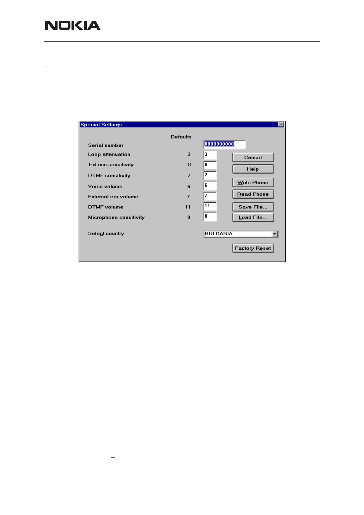
Special Settings
Activation Status Bar Text
Alt+E, S –
This command is used to change some values in EEPROM. The contents
of the EEPROM can be read to a file or from a file.
TFF-3
Service Software Instructions
The Special Settings dialog box contains the following items:
Cancel button (Alt+Esc):
The dialog box is closed.
Help button (Alt+H):
Opens help window.
Write Phone (ALT+W):
Writes special settings to the phone. Before writing the user is
asked to confirm the writing.
Read Phone (ALT+R):
Reads special settings from the phone and updates them to
the display.
Save File (ALT+S):
Writes special settings to file. You can select the file to write to
from the File selection dialog box.
Load File (ALT+L):
Reads special settings from file.
Factory Re
Issue 1 08/99
set (ALT+E):
Resets the phone to the factory values.
Nokia Mobile Phones Ltd.
Page 47
Page 48

TFF-3
Service Software Instructions
FFSK Data Sending Control
Activation Status Bar Text
Alt+E, F Wait! Initializing ...
This command is used to set the phone modem to send various signalling
frames as follows:
FFSK data transmission functions:
– signalling frame selection, with choice between 16 different types, plus
transmission of “1” state frequency (1200 Hz) or “0” state frequency (1800
Hz).
– transmit channel selection.
– number of signalling frame transmissions, with choice between one
transmission and up to nine transmissions, short frame transmission A, or
continuous frame transmission B.
PAMS Technical Documentation
– transmission tuning, selectable between tuning off (normal state) or
transmitter left on after end of transmission.
– transmit power selection.
– signalling frame transmission.
– stop sending.
Note: Use stop sending after sending even if there was only one
frame to send.
The FFSK Data Sending Control dialog box contains the following
items:
Page 48
Cancel button (Alt+Esc):
The dialog box is closed.
Help button (Alt+H):
Opens help window.
Send Frame button (Alt+S):
Sends selected frame.
Nokia Mobile Phones Ltd.
Issue 1 08/99
Page 49

PAMS Technical Documentation
Stop Sending button (Alt+P):
Stops sending. Stop sending before you select another signalling frame or another number of signalling frame transmissions
hannel (ALT+C) edit box:
Tx c
This enables editing transmit channel.
Frame to send (ALT+F) list box:
Signalling frame selection, with choice between 16 different
types, plus transmission of “1” state frequency (1200 Hz) or “0”
state frequency (1800 Hz).
Number of times to send (ALT+N) list box:
Select number of signalling frame transmissions, with choice
between one transmission and up to nine transmissions, short
frame transmission A, or continuous frame transmission B.
Se
t control (ALT+E) combo box:
TFF-3
Service Software Instructions
Transmission tuning selection, selectable between tuning off
(normal state) or transmitter left on after end of transmission.
TX level (ALT+L) combo cox:
Transmit power selection (LOW / HIGH).
Issue 1 08/99
Nokia Mobile Phones Ltd.
Page 49
Page 50

TFF-3
Service Software Instructions
Single Tone and DTMF Control
Activation Status Bar Text
Alt+E, T Wait! Initializing ...
This command displays a dialog box enabling tests of DTMF signal gen-
erator operation.
DTMF signal tests:
– DTMF signal transmission
– TX audio routing
– RX audio routing
– TX and RX audio routing
– audios muted
PAMS Technical Documentation
Page 50
The Single Tone and DTMF Control dialog box contains the following
items:
C
ancel button (Esc):
The dialog box is closed.
H
elp button (Alt+H):
Opens help window.
Nokia Mobile Phones Ltd.
Issue 1 08/99
Page 51

PAMS Technical Documentation
Specific Menu
Selecting Dealer will bring up a sub–menu as shown below:
–Call Control...
– Automatic Area Code...
– Calling Line Identification…
– Charge advice information...
– Pulse Dialing Settings…
– Immobilizer...
– Tariff Table...
TFF-3
Service Software Instructions
Issue 1 08/99
Nokia Mobile Phones Ltd.
Page 51
Page 52

TFF-3
Service Software Instructions
Call Control
Activation Status Bar Text
Alt+S, C –
This command is used to open a dialog, which helps the service person
to create a call to the certain phone number.
PAMS Technical Documentation
The Call Control dialog box contains the following items:
C
lose button (Esc):
The dialog box is closed.
H
elp button (Alt+H):
Opens help window.
Ca
ll Create (ALT+A):
The call is created by pressing this button.
Cal
l Answer button (ALT+L):
The call is answered by pressing this button.
Call R
Phone Number edit box :
elease button (ALT+R):
The call is released by pressing this button.
The user writes here the phone number into which hereThe
call is released by pressing this button.
Page 52
Nokia Mobile Phones Ltd.
Issue 1 08/99
Page 53

PAMS Technical Documentation
Automatic Area Code
Activation Status Bar Text
Alt+S, A Automatic Area Code! Reading from ME...
This command enables the user to edit/program Automatic Area Code
(AAC) information of the TFF3 terminal. AAC is a feature that enables
calling to a local number without dialling an area code. AAC is activated
by setting values to the Automatic Area Code and exception rules. If one
of them is empty the AAC feature is inactive.
TFF-3
Service Software Instructions
The Automatic Area Code dialog box contains the following items:
O
K button (Return):
The dialog box is closed
C
ancel button (Esc):
The dialog box is closed.
H
elp button (Alt+H):
Opens help window.
Get Defaults (ALT+G):
Reads Automatic area code and exception rules from TESLA.INI–file.
Set Defaults button (ALT+S):
Writes Automatic area code and exception rules to TESLA.INI–
file.
Automatic Area Code edit box:
User can enter or edit Automatic Area Code number in this edit
box. It can be any valid number (including digits 0...9 and ’+’).
Issue 1 08/99
Nokia Mobile Phones Ltd.
Page 53
Page 54

TFF-3
Service Software Instructions
The maximum length is six digits. Examples of the valid area
codes are 08, +3588.
Automatic area code is never added to an emergency number.
Exception Rules list box:
User can select exception rule line from this list. Line can be
edited in Selection edit box.
Exception rules determine the situations when area code is not
automatically inserted to a dialled number. The rules are a set
of prefixes that are searched from the beginning of the dialled
number.
Note that the area code to be added is also searched from the
beginning of the dialled number. If it is found, area code is not
automatically added.
Selection edit box:
PAMS Technical Documentation
User can edit selected exception rule in this edit box. New exception rule is added to the list box by pressing Add–button.
Selected line is removed from the listbox by pressing Delete–
button.
Add button (ALT+A):
Adds new exception rule to the listbox.
Delete button (ALT+D):
Deletes selected exception rule from the listbox.
Page 54
Nokia Mobile Phones Ltd.
Issue 1 08/99
Page 55

PAMS Technical Documentation
Calling Line Identification
Activation Status Bar Text
Alt+S, L Calling Line Identification! Reading from ME...
This command opens the Calling Line Identification dialog. In this dialog
the user can enable/disable DTMF CLI feature, select DTMF settings
froms the list and determine pulse and pause lengths in ms.
TFF-3
Service Software Instructions
The Calling line Identification dialog box contains the following items:
K button (Return):
O
The dialog box is closed
C
ancel button (Esc):
The dialog box is closed.
H
elp button (Alt+H):
Opens help window.
Default L
DTMF C
D
TMF Settings combobox (Alt+D):
The user can select from 8 different sets for DTMF CLI settings. Each set
contains 6 variables, which are:
1– line reversal
engths button (Alt+L):
Default pulse and pause lengths (90 ms) are set to the phone.
LI in use checkbox (Alt+C):
Sets Calling Line Identification feature ON/OFF. If checked CLI
feature is ON. Otherwise OFF.
2– TAS type (TAS=Terminal Alerting Signal)
Issue 1 08/99
Some DTMF CLI display devices require line polarity reversal
before displaying the CLI number.
In some DTMF type CLI systems phone ringing...
Nokia Mobile Phones Ltd.
Page 55
Page 56

TFF-3
Service Software Instructions
3– TAS pause
This value is delay time in milliseconds between ringing and
CLI number sending to display device. It is used only when
TAS type ringing pattern is selected.
4– POST Transmission Pause
Delay time after the CLI number has been sent into the display
device. After that phone is set ringing.
5– start code type
Display devices use DTMF tone A to detect start of CLI number tone sequence.
6– end code type
Display devices use DTMF tone C or # to detect end of CLI
number tone sequence.
Contents of the sets:
PAMS Technical Documentation
SET 1:
SET 2:
SET 3:
– line reversal Not used
– TAS type Not used
– TAS pause 1000 ms
– POST Transmission Pause 100 ms
– start code type DTMF tone A
– end code type DTMF tone C
– line reversal Not used
– TAS type Not used
– TAS pause 1000 ms
– POST Transmission Pause 100 ms
– start code type DTMF tone A
– end code type DTMF tone #
Page 56
– line reversal Not used
– TAS type Ringing pattern, 1s delay
– TAS pause 1000 ms
– POST Transmission Pause 250 ms
– start code type DTMF tone A
– end code type DTMF tone C
Nokia Mobile Phones Ltd.
Issue 1 08/99
Page 57

PAMS Technical Documentation
SET 4:
– line reversal Not used
– TAS type Ringing pattern, 1s delay
– TAS pause 1000 ms
– POST Transmission Pause 250 ms
– start code type DTMF tone A
– end code type DTMF tone #
SET 5:
– line reversal 100 ms
– TAS type Not used
– TAS pause 1000 ms
– POST Transmission Pause 100 ms
TFF-3
Service Software Instructions
SET 6:
SET 7:
– start code type DTMF tone A
– end code type DTMF tone C
– line reversal 100 ms
– TAS type Not used
– TAS pause 1000 ms
– POST Transmission Pause 100 ms
– start code type DTMF tone A
– end code type DTMF tone #
– line reversal 100 ms
– TAS type Ringing pattern, 1s delay
– TAS pause 1000 ms
– POST Transmission Pause 250 ms
– start code type DTMF tone A
SET 8:
Issue 1 08/99
– end code type DTMF tone C
– line reversal 100 ms
– TAS type Ringing pattern, 1s delay
– TAS pause 1000 ms
– POST Transmission Pause 250 ms
– start code type DTMF tone A
– end code type DTMF tone #
Nokia Mobile Phones Ltd.
Page 57
Page 58

TFF-3
Service Software Instructions
Charge Advice Information
Activation Status Bar Text
Alt,+S, H Charge Advice Information! Reading from ME...
This command opens the Charge Advice Information dialog. In this dia-
log, the user can enable/disable payphone feature, select frequency (12
kHz or 16 kHz) and determine pulse / pause lengths in ms.
PAMS Technical Documentation
The Charge Advice Information dialog box contains the following items:
OK button (Return, ALT+O):
Writes CAI settings to the terminal.
Cancel button (Esc):
The dialog box is closed.
Help button (Alt+H):
Opens help window.
Get Defaults button (Alt+G):
Reads default CAI settings from TESLA.INI file.
Set Defaults button (Alt+S):
Writes default CAI settings to TESLA.INI file.
Payphone is enabled checkbox (Alt+P):
If checked enables payphone feature. If not checked, payphone feature is disabled.
State combobox (Alt+S):
User can select 12kHz /16 kHz frequency from this combobox.
Page 58
Length edit box (Alt+L):
The user can edit pulse length here (default value is 150 ms).
Interval edit box (Alt+I):
The user can edit pause length here (default value is 350 ms).
Nokia Mobile Phones Ltd.
Issue 1 08/99
Page 59

PAMS Technical Documentation
Pulse Dialing Settings
Activation Status Bar Text
Alt,+S, P Pulse Dialing Settings! Reading from ME...
This command opens the Pulse Dialing Settings dialog in which the user
can enter / edit following settings:
– off hook detection time 50 ms
– on hook detection time 80 ms
– minimum pulse length 20 ms
– maximum pulse length 200 ms
– minimum pause length 15 ms
– maximum pause length 50 ms
– minimum time between two R–keys 0 ms
– minimum length of R–keys 0 ms
– maximum length of R–keys 0 ms
TFF-3
Service Software Instructions
Default values:
The Pulse Dialing Settings dialog box contains the following items:
OK button (Return, ALT+O):
ancel button (Esc, Alt +C);
C
elp button (Alt+H):
H
ave File button (Alt+S):
S
Issue 1 08/99
The pulse dialing settings are written to the terminal and thedialog box is closed.
The dialog box is closed.
Opens help window.
Asks the user to give a filename into which the pulse dialing
settings are to be written. Default file name is DEFAULT.PDS.
Nokia Mobile Phones Ltd.
Page 59
Page 60

TFF-3
Service Software Instructions
Load File button (Alt+L):
Loads the pulse dialing settings from a file given by the user.
mmobilizer
I
Activation Status Bar Text
Alt+S, I Immobilizer! Reading from ME...
This command opens the immobilizer dialog. In this dialog the user can
set immobilizer features.
PAMS Technical Documentation
The Immobilizer dialog box contains the following items:
O
K button (Return):
The immobilizer features are written to the phone and ,
ancel button (Esc):
C
The dialog box is closed.
elp button (Alt+H):
H
Opens help window.
Reset Immo button (ALT+R):
When the phone is assembled into final location (mounting
plate, immobilizer can be set on by pressing this button.
Immobilizer is in use combobox (ALT+I):
Sets immobilizer feature ON / OFF.
Immobilizer A
uto Install combobox (ALT+A):
If Immobilizer Auto Install is chosen, the phone will make automatic immobilizer installation when switched on for the next
time.
Page 60
The phone must be assembled into mounting plate before switching on,
otherwise the calling prohibition is set on and only emergency calls are
possible.
Immobilizer Auto Install requires that the immobilizer feature is also set
on.
Nokia Mobile Phones Ltd.
Issue 1 08/99
Page 61

PAMS Technical Documentation
Tariff Table
Activation Status Bar Text
Alt+S, T Tariff Table! Reading from ME...
This command opens the Tariff Table dialog. In this dialog the user can
determine whether the terminal uses default tariff table or user defined
tariff table. Default tariff table is in terminals SW and it can’t be modified
by the user. User defined tariff is written to terminal’s EEPROM and it can
be modified.
TFF-3
Service Software Instructions
The Tariff Table dialog box contains the following items:
O
K button (Return, Alt+O):
ancel button (Esc, Alt+C):
C
H
elp button (Alt+H):
Issue 1 08/99
The tariff table information is written to the terminal and the
dialog is closed.
The dialog box is closed.
Opens help window.
Nokia Mobile Phones Ltd.
Page 61
Page 62

TFF-3
Service Software Instructions
Set Defaults (ALT+S):
Sets default values to the tariff table and writes them to terminal’s EEPROM. Default values are also updated to the dialog.
D
efault tariff table in use radio buttont (ALT+D):
When selected the terminal uses default tariff table. The user
cannot modify the tariff table values.
ser defined tariff table in use radio buttont (ALT+U):
U
When selected the terminal uses EEPROM tariff table. The
user can modify the tariff table values.
Q1Q2 Price/call comboboxes 0– 20:
These comboboxes show tariff table values Q1Q2 from index
0 to 20. User can select that Q1Q2 is not used or Q1Q2 has
value between 0.25… 30.0. Move to next combobox by pressing TAB.
PAMS Technical Documentation
Q1Q2 Price/time listbox:
This listbox displays tariff table values from index 21 to 255.
Select value from the list and edit it in edit selected value editbox. The user can use arrow keys, Page Up/Down keys or
mouse in order to stroll the listbox.
Edit selected value editbox:
The user can edit the selected tariff table value (index es
21...255) in this edit box. After editing pressing TAB sets the
focus on the Q1Q2 Pric/time listbox. The user can use arrow
keys, Page Up/Down keys or mouse in order to change the listbox selection.
Page 62
Nokia Mobile Phones Ltd.
Issue 1 08/99
Page 63

PAMS Technical Documentation
Dealer Menu
Selecting Dealer will bring up a sub–menu with the following items:
–Subscriber Data…
– Traffic Areas...
– Warranty Information
– Country Codes
S
ubscriber Data
Activation Status Bar Text
Alt+D, S –
Selecting Dealer/Subscriber Data opens the subscriber data dialog box.
In this dialog, you can view and edit phone’s current subscriber data. The
TFF–3 phone must be in local mode while writing subscriber data.
TFF-3
Service Software Instructions
The Subscriber Data dialog box contains the following items:
Cancel button (Alt+Esc):
Help button (Alt+H):
Write Phone button (ALT+W):
Subscriber Number (ALT+U) edit box:
Issue 1 08/99
The dialog box is closed.
Opens help window.
Writes subscriber data to the phone. Before writing the user is
asked to confirm the writing.
This enables programming a country code, which is a six–figure subscriber number and a three–figure password as follows:
Nokia Mobile Phones Ltd.
Page 63
Page 64

TFF-3
Service Software Instructions
Z X 1 X 2 X 3 X 4 X 5 X 6 K 1 K 2 K 3 , where
Z is country selection as follows:
2 The Netherlands
3 Poland, Ukraine
4 Island/Estonia/OSS Carelian rep./Latvia/Lithuania/
5 Denmark
6 Sweden
7 Norway
8 Finland
X 1 – X 6 is the subscriber number
K 1 – K 3 is the password
PAMS Technical Documentation
Romania/Bulgaria/OSS St. Petersburg/OSS Lenin
grad dist. / OSS Moscow/OSS Murmansk/Algeria
Delivery Date (ALT+D) edit box:
This enables entering the date of delivery in the form
mmyyyy
where mm is the month using two figures and yy represents
the year as a two–figure number.
Repair Date (ALT+P) edit box:
Repair date is programmed every time the phone has been repaired.
The format of the repair date is
mmyy
where mm is the month using two figures and yy represents
the year as a two–figure number.
Sub
scriber type (ALT+B) combobox:
The user can select subscriber type from following list:
1. National,
2. Regional.
If regional is selected, the traffic areas must also be written to
the phone.
Page 64
untry Location (ALT+O) combobox:
Co
With TFF3SP the user can select country location from following list:
0 DK,
1 SE,
2 NO,
3 FI,
4 IS,
Nokia Mobile Phones Ltd.
Issue 1 08/99
Page 65

PAMS Technical Documentation
5 FO,
6 EE,
7 LV,
8 LT,
9 BY,
10 MO,
11 SP,
12 PL,
13 BG,
14 RO,
15 RU1,
16 RU2,
17 RU3,
18 RU4,
19 S2.
The list contains only two countries with TFF3C and TFF3T.
TFF-3
Service Software Instructions
less Local Loop (ALT+E) combobox:
Wire
Local loop state can be set OFF/ ON from this combobox.
Basic Band 1 First (ALT+1) edit box:
This number defines the first channel searched for the call. In
the Nordic countries the value 1 applies.
Basic Band 1 Last (ALT+I) edit box:
This number defines the last channel from which the calling
channel is searched.
The value for the Nordic countries is 180.
Basic Band 2
Band 2 Last (ALT+C) edit box:
Basic
Scrambler enabled/disabled checkbox:
First (ALT+2) edit box:
This edit box is shown only in Poland and Hungary, where two
band phones are used. This number defines the first channel
for Band 2 phones.
This edit box is shown only in Poland and Hungary. This number defines the last channel for Band 2 phones.
Issue 1 08/99
When checked, scrambler feature is enabled. If not checked,
scrambler is disabled.
Nokia Mobile Phones Ltd.
Page 65
Page 66

TFF-3
Service Software Instructions
Traffic Areas
Activation Status Bar Text
Alt+D, T –
PAMS Technical Documentation
The Traffic Areas dialog box contains the following items:
Cancel button (Alt+Esc):
The dialog box is closed.
Help button (Alt+H):
Opens help window.
Write Phone (ALT+W):
Writes traffic area information to the phone.
Read Phone (ALT+R):
Reads trafffic area information from the phone and updates it
to the display.
Save File (ALT+S):
Writes traffic area information to file. You can select the file to
write to from the File selection dialog box.
Load File (ALT+L):
Reads traffic area information from file. You can select a file to
be loaded from the File selection dialog box.
Page 66
Clear All Areas :
Clears all traffic area information from the dialog and writes it
to the phone.
Clear 00…0F :
Clears selected traffic area information from the dialog and
writes it to the phone.
Nokia Mobile Phones Ltd.
Issue 1 08/99
Page 67

PAMS Technical Documentation
Warranty Information
Activation Status Bar Text
Alt+D, W –
Selecting Dealer/Warranty Information opens the Warranty Information
dialog. In this dialog, you can view serial number, delivery date, software /
hardware versions, SIS–reference, latest dealer codes and repair dates.
TFF-3
Service Software Instructions
The Warranty Information dialog box contains the following items:
Cancel button (Alt+Esc):
The dialog box is closed.
Help button (Alt+H):
Opens help window.
Read Phone (ALT+R):
Reads warranty information from the phone and updates it to
the display.
Issue 1 08/99
Nokia Mobile Phones Ltd.
Page 67
Page 68

TFF-3
Service Software Instructions
Country Codes
Activation Status Bar Text
Alt+D, C –
Selecting Dealer/Country Codes opens the country codes dialog box. In
this dialog, you can view and edit codes / emergency numbers of the
phone.
PAMS Technical Documentation
Example of country codes:
B Belgium
BY Belorussia
CS Czechoslovakia, Slovak
DK Denmark
EE, EW Estonia
FI Finland
FO Faroe Islands
HU Hungary
IS Iceland
LT Lithuania
LU Luxemburg
LV Latvia
MO Moscow
NL Holland
NO Norway
PL Poland
SE Sweden
SP St. Petersburg
Page 68
Nokia Mobile Phones Ltd.
Issue 1 08/99
Page 69

PAMS Technical Documentation
The Country Codes dialog box contains the following items:
Cancel button (Alt+Esc):
The dialog box is closed.
Help button (Alt+H):
Opens help window.
Write Phone (ALT+W):
Writes country codes to the phone. Before writing the user is
asked to confirm the writing.
Read Phone (ALT+R):
Reads country codes from the phone and updates them to the
display.
Save File (ALT+S):
TFF-3
Service Software Instructions
Saves country codes to a file. Before saving the file name is
asked.
Load File (ALT+R):
Loads country codes from the file and updates them to the display.
Se
lect Country Location (ALT+E):
User can select country location which is written to the phone.
Y1 (ALT+Y),
ID (ALT+ I),
emerg 1 (ALT + 1),
emerg 2 (ALT + 2),
emerg 3 (ALT + 3) edit boxes:
These enable editing and entering country ID and emergency
numbers.
Note: Country Code can’t be edited.
Issue 1 08/99
Nokia Mobile Phones Ltd.
Page 69
Page 70

TFF-3
Service Software Instructions
View Menu
Selecting View will bring up a sub–menu as shown below:
hone Identity
P
Activation Status Bar Text
Alt, V, P –
This command is used for opening Phone Identity Information dialog. In
this dialog one can view phone’s serial number, delivery date, sw– and
hw–versions and SIS – reference.
PAMS Technical Documentation
The Phone Identity Information dialog box contains the following items:
Close button (Alt+F4):
The dialog box is closed.
Page 70
Nokia Mobile Phones Ltd.
Issue 1 08/99
Page 71

PAMS Technical Documentation
Help Menu
The Help Menu offers commands, which provide assistance with this application.
I
ndex
Activation Status Bar Text
Alt, H, I –
Not implemented
G
eneral Help
Activation Status Bar Text
Alt, H, G
Not implemented.
TFF-3
Service Software Instructions
U
sing Help
Activation Status Bar Text
Alt, H, U
Not implemented.
A
bout WinTesla
Activation Status Bar Text
Alt, H, A Shows the WinTesla software version,
user interface, M2BUS support, and
THF–11 supporting DLL versions.
Issue 1 08/99
Nokia Mobile Phones Ltd.
Page 71
Page 72

TFF-3
Service Software Instructions
Appendix 1, Vocabulary
Abbreviation Description
AAC Automatic Area Code
API Application Programming Interface
ASIC Custom circuit which for instance controls
CAI Charge Advice Information
CLF Common Look and Feel
CLI Calling Line Identification
DATA DATA interface module
DLL Dynamic Link Library
PAMS Technical Documentation
communication between MCU and DSP
EEPROM Memory for adjustment parameters (Electrically
Erasable and Programmable Read Only Memory)
M2BUS Serial communication bus which can be connected
to accessory devices and test PC
MCU Master Control Unit processor
ME Mobile Equipment
MFC Microsoft Foundation Class library
MS Mobile Station
MTI Message Transfer Interface
PC IBM PS/AT or compatible personal computer
PCBOX Local Net driver SW for PC
PCI Phone Controlling Interface SW for PC
PKD Parallel Port Software Protection Device
RF Radio Frequency parts
SW Software
UI User Interface
Page 72
Nokia Mobile Phones Ltd.
Issue 1 08/99
 Loading...