

Page 1

PAMS Technical Documentation
TFF-3 WLL Transceivers
General Information
Issue 1 08/99 Nokia Mobile Phones Ltd.
Page 2
TFF-3
General Information
PAMS Technical Documentation
AMENDMENT RECORD SHEET
Amendment
Number
Date Inserted By Comments
08/99 OJuntune Original
Page 2
Nokia Mobile Phones Ltd.
Issue 1 08/99
Page 3

PAMS Technical Documentation
General Information
CONTENTS
Product Selection 2 – 4. . . . . . . . . . . . . . . . . . . . . . . . . . . . . . . . . . . . . . .
Module and Product Lists 2 – 5. . . . . . . . . . . . . . . . . . . . . . . . . . . . . . . .
Technical Specifications 2 – 6. . . . . . . . . . . . . . . . . . . . . . . . . . . . . . . . .
General Specifications of Transceiver TFF–3 2 – 6. . . . . . . . . . . . .
Transceiver features 2 – 6. . . . . . . . . . . . . . . . . . . . . . . . . . . . . . . .
Dimensions 2 – 6. . . . . . . . . . . . . . . . . . . . . . . . . . . . . . . . . . . . . . .
Modes of Operation 2 – 6. . . . . . . . . . . . . . . . . . . . . . . . . . . . . . . .
Environmental Specifications 2 – 6. . . . . . . . . . . . . . . . . . . . . . . .
Maximum ratings 2 – 7. . . . . . . . . . . . . . . . . . . . . . . . . . . . . . . . . . .
DC Characteristics 2 – 7. . . . . . . . . . . . . . . . . . . . . . . . . . . . . . . . .
AC Characteristics 2 – 8. . . . . . . . . . . . . . . . . . . . . . . . . . . . . . . . .
Transmitter branch specifications 2 – 8. . . . . . . . . . . . . . . . . .
Receiver branch specifications 2 – 8. . . . . . . . . . . . . . . . . . . .
External Connections 2 – 9. . . . . . . . . . . . . . . . . . . . . . . . . . . . . . .
List of connectors 2 – 9. . . . . . . . . . . . . . . . . . . . . . . . . . . . . . . .
Power supply connector 2 – 9. . . . . . . . . . . . . . . . . . . . . . . . . .
System connector 2 – 10. . . . . . . . . . . . . . . . . . . . . . . . . . . . . . . .
Land–line connector 2 – 11. . . . . . . . . . . . . . . . . . . . . . . . . . . . . .
Interconnection diagram 2 – 12. . . . . . . . . . . . . . . . . . . . . . . . . . . .
TFF-3
Page No
Issue 1 08/99
Nokia Mobile Phones Ltd.
Page 3
Page 4
TFF-3
General Information
Product Selection
TFF–3 is a WLL–terminal for the NMT450 network. New features include:
CLI (calling line indicator), scrambling (voice coding), immobilizer and metering pulse generator. The operating voltage for logic chips is 2.8V and
because of ROMless CPU, external program memory (flash) is used.
PAMS Technical Documentation
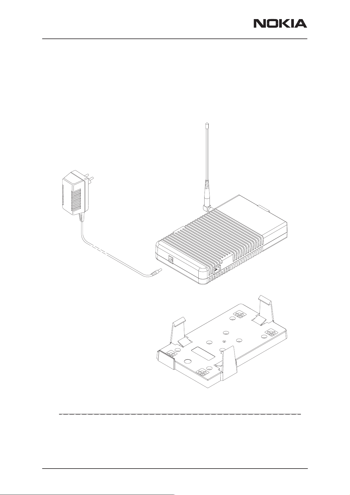
2.
3.
1.
4.
Item Name: Type code: Material code:
1. Transceiver TFF–3 0600127
2. Antenna AMF–4S 0660064
3. AC adapter EURO plug ACL–3E 0680015
4. Mounting Plate MBM–5 0620052
Page 4
Nokia Mobile Phones Ltd.
Issue 1 08/99
Page 5

PAMS Technical Documentation
Module and Product Lists
TFF-3
General Information
Name of module Type des. Material
code
Transceiver TFF–3 0600127 WLL Terminal, SP
System/RFmodule JM1 0201338
Assembly parts MTFF3 0261932
Power supply ACL–3E 0680015 EURO plug
Mounting plate MBM–5 0620052 Holder, installation kit included
Installation kit HHS–9 0253996
Antenna AMF–4S 0660064
Backup battery BBW–3 0670208 Optional accessory
Notes
Issue 1 08/99
Nokia Mobile Phones Ltd.
Page 5
Page 6

TFF-3
General Information
PAMS Technical Documentation
Technical Specifications
General Specifications of Transceiver TFF–3
If the TFF–3 is used with Polish settings, the frequency range and number of channels in parenthesis shall apply.
Transceiver features
Parameter Notes
Cellular system NMT450
TX frequency band 453.000–457.475 MHz (452.500–457.475 MHz)
RX frequency band 463.000–467.475 MHz (462.500–467.475 MHz)
Duplex spacing 10 MHz
Number of RF channels 180 (200)
Channel spacing 25 kHz
Maximum output power 7 W
Method of frequency sythesis Dual direct PLL
Power Supply Voltage 10.6... 14.5 V nominal 13.5 V
Dimensions
Item Dimensions (mm)
(W x H x D)
TFF–3
only with covers
all items
ACL–3E (accessory) 100x88x63 290 black
BBW–3 (optional accessory) 177x180x48 1900 Infralib
200x114x32
210x122x54
Weight
(g)
690
900
Color Notes
Infralib
8705
8705
Modes of Operation
Listening and conversation
Environmental Specifications
TFF–3 can dissipate almost 40W of heat to radiator. The temperature inside the TFF–3 case must not exceed 85 °C.
Parameter Ambient temperature Notes
Operating temperature range –25C to +55 °C
Reduced operating temperature range –25C to +85 °C
Storage temperature range –40C to +85 °C
Page 6
Nokia Mobile Phones Ltd.
Issue 1 08/99
Page 7

PAMS Technical Documentation
Maximum ratings
Parameter Rating
Power supply voltage 14.5V
Humidity and dust IP52
Operating temperature range –25C to +55 C
Reduced operating temperature range –25C to +85 C
Storage temperature range –40C to +85 C
DC Characteristics
TFF-3
General Information
Line Symbol Minimum Typical /
Nominal
Input supply voltage (VB) 10.6 13.5 14.5 V
Input supply current (I_VB) 3.3 A
Regulated supply voltage (VS) 4.75 5.0 5.25 V (to PSA)
Regulated supply current (I_VS) 0.4 A
Regulated logic supply voltage (VL) 2.73 2.82 2.85 V (from PSA to
Regulated logic supply current (I_VL) 40 mA
Regulated audio supply voltage (VA) 2.73 2.82 2.85 V (from PSA to
Regulated audio supply current (I_VA) 100 mA
Regulated RX supply voltage (VRX) 2.73 2.82 2.90 V (from PSAto
Regulated RX supply current (I_VRX) 50 mA
Regulated TX supply voltage (VTX) 2.73 2.82 2.90 V (from PSA to
Regulated TX supply current (I_VTX) 0.02 60 mA
Regulated TX buffer supply voltage (VPC) 7.6 8.0 8.4 V
Maximum Unit / Notes
logic)
audio)
RF–RX)
RF–TX)
Regulated TX buffer supply current
(I_VPC)
Regulated SIS supply voltage (VSIS) 3.15 3.3 3.45 V
Regulated flash supply voltage (VPROG) 3.15 3.3 3.45 V
Regulated flash supply current (I_VPROG) 30 mA
Current consumption conv. low mode 0.8 A
Current consumption conv. medium power 1.3 A
Current consumption conv. high power 2.8 A
Issue 1 08/99
Nokia Mobile Phones Ltd.
300 mA
Page 7
Page 8

TFF-3
ratio
General Information
PAMS Technical Documentation
AC Characteristics
Transmitter branch specifications
Parameter Rating
Frequency band 452.500–457.475MHz
Output RF power 0.15, 1.5 or 7.0 W
Spurious signals (TX ON)
Spurious signals (STANDBY)
Modulation method FM
Deviation 4.7 kHz max
Deviation with supervisory signal 5.0 kHz max
FFSK deviation 1200 Hz (”1”)
1800 Hz (”0”)
Harmonic distortion < 5 %
Audio Frequency responce 300–500 Hz
500–2000 Hz
2–3 KHz
pre–emphasis
Adjacent Channel Power < –70 dBc
Audio Intermodulation products < –20 dB
Residual Modulation linear
psophometric
< 0.25 uW, f = 100kHz – 1GHz
< 1 uW, f = 1GHz – 4GHz
< 2 nW, f = 100kHz – 1GHz
< 20 nW, f = 1GHz – 4GHz
2800 Hz dev. +/– 400 Hz
4200 Hz dev. +/– 600 Hz
+1–3 dB
+/– 1 dB
+1–3 dB
6 dB/Oct
< –20 dB (peak)
< –40 dB (rms)
Audio Muting > 40 dB
Compander SW enabled compression
dynamic range
Number of power levels 3
Frequency error +/– 2.5 kHz
2:1
3 – –50 dB +/– 1 dB
Receiver branch specifications
Parameter Rating
Frequency band 462.500–467.475MHz
Sensitivity –113 dBm (20 dB SINAD psoph. )
Adjacent Channel Selectivity > 67 dB
Spurious Responce Rejection > 67 dB
Intermodulate Rejection > 67 dB
Page 8
Nokia Mobile Phones Ltd.
Issue 1 08/99
Page 9

PAMS Technical Documentation
ratio
Blocking > 87 dB
TFF-3
General Information
RatingParameter
Spurious signals (TX OFF)
Audio Intermodulation Products < –20 dB ( refer to 1600 Hz)
AM suppression > 30 dB
Hum and Noise linear
phopsometric
Audio Frequency responce 300–500 Hz
500–2000 Hz
2–3 KHz
de–emphasis
Harmonic distortion <5 %
Audio Muting > 50 dB
Expander SW enabled compression
dynamic range
RSSI dynamic range 60 dB
< 2 nW, f = 100kHz – 1GHz
< 20 nW, f = 1GHz – 4GHz
< –20 dB (peak to peak)
< –40 dB (rms)
+1–3 dB
+/– 1 dB
+1–3 dB
6 dB/Oct
1:2
3 – –50 dB +/– 1 dB
External Connections
List of connectors
Connector Name Code Notes
System 5416518
Land–Line 5409043
RF Antenna 5426384
Power Supply 5414943
Power supply connector
Pin Name Min Typ Max Unit Notes
1 VB 10.6 13.5 14.5 V Power Supply voltage, max current 3.5A
2 GND 0 0 V Supply ground
3 NC
Issue 1 08/99
Nokia Mobile Phones Ltd.
Page 9
Page 10

TFF-3
Baud rate 9600 Bit/s
General Information
PAMS Technical Documentation
System connector
The system connector is used as a flash memory programming interface
for updating (i.e. re–programming) the flash program memory.
Pin Name Min Typ Max Unit Notes
7 VSF 6.0 14.5 V Power supply (INPUT ONLY) for flash-
ing
5 GND 0 0 V Supply ground
3 M2BUS 0 logic low
2.0 logic high 2.85
1 FBUS_RX 0
2.0
2 FBUS_TX 0
2.0
4 AGND 0 0 V Analog supply ground
6 XMIC 2.0 2.2
8 XEAR 47
logic low
logic high
logic low
logic high
4.7
1.0
22
0.8 V Serial bidirectional control bus.
Phone has a 4k7 pullup resistor
0.8
2.85
0.5
2.85
1
10
626
V Fbus receive. Serial Data for flashing
Baud rate 9.6k–230.4kBit/s
Phone has a 220k pulldown resistor
V Fbus transmit. Serial Data for flashing
Baud rate 9.6k–230.4kBit/s
Phone has a 47k pullup resistor
kΩ
Vpp
Ω
kΩ
Vpp
mV
Input AC impedance
Maximum signal level
Output AC impedance (ref. GND)
Load AC impedance to AGND
Maximum output level (no load)
Output signal level
System connector front view is in the diagram below.
Page 10
8642135786421357
Nokia Mobile Phones Ltd.
Issue 1 08/99
Page 11

PAMS Technical Documentation
Land–line connector
The land–line connector is used to connect SLIC circuitry to land–line
phone.
The landline telephone is one of main user interfaces of the WLL terminal.
A standard landline telephone can be used. Both pulse dialling and
DTMF are supported in System Solution and Non–Transparent Access
Solution modes.
However. only DTMF dialling is supported in Transparent Acces Solution
mode.
Main parameters :
– nominal impedance is 600 ohm
– feeding Voltage –52 V +/– 3 V
– ringing Voltage –68 Vrms +/–3V
– max. 2–wire lenght is 100 m (with one connected telephone)
– 3 telephones parallel
TFF-3
General Information
Table 1. Land–line Connector
Pin Name Min Typ Max Unit Notes
3 GND 0 0 V Ground
4 GND 0 0 V Ground
1 TIP –4 –80 V TIP line
2 RING –4 –80 V RING line
5 GND 0 0 V Ground
6 GND 0 0 V Ground
The connector, front view below, has irregular numbering order.
642135
Issue 1 08/99
Nokia Mobile Phones Ltd.
Page 11
Page 12

TFF-3
General Information
Interconnection diagram
Interconnection diagram below.
PAMS Technical Documentation
AC –cord
BBW–3
backup
battery
DC–cords
Power
supply
DC –
connector
TFF–3
Antenna
connector
System
connector
Line
adapter
connector
to service equipment
to landline phone
Page 12
Nokia Mobile Phones Ltd.
Issue 1 08/99
 Loading...