

Page 1

Cellular Networks
FCC ID: IHET4KJ1
LTE WBR FDD Frame Based Radio @ 700MHz
APPLICANT: MOTOROLA
Users Manual Exhibit
FCC Filing – LTE WBR FDD Frame Based Radio @ 700MHz
Page 2

LTEeNodeBIndoorHardwareInstallation
68P09308A55-6FEB2010
©2009-2010Motorola,Inc.AllRightsReserved
Page 3

Accuracy
Whilereasonableeffortshavebeenmadetoassuretheaccuracyofthisdocument,Motorola,Inc.assumesno
liabilityresultingfromanyinaccuraciesoromissionsinthisdocument,orfromuseoftheinformationobtained
herein.Motorola,Inc.reservestherighttomakechangestoanyproductsdescribedhereintoimprovereliability ,
function,ordesign,andreservestherighttorevisethisdocumentandtomakechangesfromtimetotimeincontent
hereofwithnoobligationtonotifyanypersonofrevisionsorchanges.Motorola,Inc.doesnotassumeanyliability
arisingoutoftheapplicationoruseofanyproduct,software,orcircuitdescribedherein;neitherdoesitconvey
licenseunderitspatentrightsortherightsofothers.Itispossiblethatthispublicationmaycontainreferencesto,or
informationaboutMotorolaproducts(machinesandprograms),programming,orservicesthatarenotannounced
inyourcountry.SuchreferencesorinformationmustnotbeconstruedtomeanthatMotorolaintendstoannounce
suchMotorolaproducts,programming,orservicesinyourcountry.
Copyrights
Thisdocument,Motorolaproducts,and3rdPartySoftwareproductsdescribedinthisdocumentmayinclude
ordescribecopyrightedMotorolaandother3rdPartysuppliedcomputerprogramsstoredinsemiconductor
memoriesorothermedia.LawsintheUnitedStatesandothercountriespreserveforMotorola,itslicensors,and
other3rdPartysuppliedsoftwarecertainexclusiverightsforcopyrightedmaterial,includingtheexclusiveright
tocopy ,reproduceinanyform,distributeandmakederivativeworksofthecopyrightedmaterial.Accordingly,
anycopyrightedmaterialofMotorola,itslicensors,orthe3rdPartysoftwaresuppliedmaterialcontainedinthe
Motorolaproductsdescribedinthisdocumentmaynotbecopied,reproduced,reverseengineered,distributed,
mergedormodiedinanymannerwithouttheexpresswrittenpermissionofMotorola.Furthermore,thepurchase
ofMotorolaproductsshallnotbedeemedtogranteitherdirectlyorbyimplication,estoppel,orotherwise,any
licenseunderthecopyrights,patentsorpatentapplicationsofMotorolaorother3rdP artysuppliedsoftware,
exceptforthenormalnon-exclusive,royaltyfreelicensetousethatarisesbyoperationoflawinthesaleofa
product.
Restrictions
Softwareanddocumentationarecopyrightedmaterials.Makingunauthorizedcopiesisprohibitedbylaw .Nopart
ofthesoftwareordocumentationmaybereproduced,transmitted,transcribed,storedinaretrievalsystem,or
translatedintoanylanguageorcomputerlanguage,inanyformorbyanymeans,withoutpriorwrittenpermission
ofMotorola,Inc.
LicenseAgreements
ThesoftwaredescribedinthisdocumentisthepropertyofMotorola,Incanditslicensors.Itisfurnishedbyexpress
licenseagreementonlyandmaybeusedonlyinaccordancewiththetermsofsuchanagreement.
HighRiskMaterials
Components,units,or3rdPartyproductsusedintheproductdescribedhereinareNOTfault-tolerantandareNOT
designed,manufactured,orintendedforuseason-linecontrolequipmentinthefollowinghazardousenvironments
requiringfail-safecontrols:theoperationofNuclearFacilities,AircraftNavigationorAircraftCommunication
Systems,AirTrafcControl,LifeSupport,orW eaponsSystems(HighRiskActivities).Motorolaanditssupplier(s)
specicallydisclaimanyexpressedorimpliedwarrantyoftnessforsuchHighRiskActivities.
Trademarks
MotorolaandtheStylizedMLogoareregisteredintheUSPatent&TrademarkOfce.Allotherproductorservice
namesarethepropertyoftheirrespectiveowners.
TheCEmarkconrmsMotorola,Inc.statementofcompliancewithEUdirectivesapplicabletothisproduct.Copies
oftheDeclarationofComplianceandinstallationinformationinaccordancewiththerequirementsofEN50385can
beobtainedfromthelocalMotorolarepresentativeorbycontactingtheCustomerNetworkResolutionCenter
(CNRC).The24hourtelephonenumbersarelistedath
NetworkResolutionCentercontactinformation.AlternativelyifyoudonothaveaccesstoCNRCorthe
internet,contacttheLocalMotorolaOfce.
ttps://mynetworksupport.motorola.com.SelectCustomer
FEB2010
Page 4

Table
Contents
Contents
■■■■■■■■■■■■■■■■■■■■■■■■■■■■■■■■■■■■■■■■■■■■■■■■■■■■■■■■■■■■■
LTEeNodeBIndoorHardwareInstallation
Revisionhistory.........................................2
Versioninformation.....................................2
Releaseinformation.....................................2
ResolutionofServiceRequests...............................2
Generalinformation.......................................3
Purpose...........................................3
Crossreferences.......................................3
Documentbannerdenitions................................3
Textconventions.......................................4
ContactingMotorola.......................................5
24–hoursupport.......................................5
OrderingdocumentsandCD-ROMs.............................5
Questionsandcomments..................................5
Errors............................................5
of
■
■
■
■
Chapter1:Introduction
Overview.............................................1-2
Notaplanningguide.....................................1-2
Followthesiteplan.....................................1-2
Prerequisites.........................................1-2
Systemshippedunassembled................................1-2
ProductDescription.....................................1-3
MajorComponentswithCall-outs................................1-5
Congurationssupported....................................1-7
Chapter2:Sitepreparation
Overview.............................................2-2
Preparingthesiteforequipmentarrival...........................2-2
LTEeNodeBComponentDimensions............................2-4
Framedimensionsandclearances..............................2-5
ElectricalRequirements.....................................2-7
Cabinetvoltage.......................................2-7
DCsupplyequipment,Maincircuitbreaker ,andDCinputcable...............2-7
Sitegrounding........................................2-9
EnvironmentRequirements...................................2-10
Operatingtemperaturerange................................2-10
CableRequirements.......................................2-11
eNodeBCableDescriptions(min90Cinsulationrating)...................2-13
ToolsrequiredforinstallingtheeNodeBcomponents......................2-15
68P09308A55-6i
FEB2010
Page 5

Contents
Chapter3:Frame-basedeNodeBInstallation
Overview.............................................3-2
UnpackingEquipment......................................3-5
Installationoftherack......................................3-6
Rackandgroundcableinstallation.............................3-6
Installingthe+27Vdc(PDU)..................................3-9
Requiredmaterialsandtools.................................3-9
InstallingthePDU......................................3-9
InstallationoftheBCUII.....................................3-14
Requiredmaterialsandtools.................................3-14
BCUIIinstallation......................................3-15
InstallationofRadio/FilterShelf(RFS)andFrameMountedRadioHead............3-19
RFSpowercableinstallation.................................3-22
RFSGroundCableInstallation................................3-23
InstallationoftheGPS......................................3-25
InstallingRFGPSantennaandcable.............................3-25
Optionalequipment.......................................3-28
Quartz-highstabilityoscillator................................3-28
Chapter4:InstallationoftheindoorportionsoftheRemoteRFbasedeNodeB
InstallationoftheBCUII.....................................4-2
Requiredmaterialsandtools.................................4-2
BCUIIinstallation......................................4-3
Chapter5:InstallationoftheRRH
InstallingtheRemoteRadioHead................................5-2
Installingthe700MHzRRH.................................5-2
700MHzRRHpolemountconguration...........................5-9
700MHzRRHconnections.................................5-16
Installationof2.1/2.6GHzRRH...............................5-17
2.1/2.6GHzRRHpolemountconguration.........................5-19
2.1/2.6GHzRRH......................................5-21
Chapter6:CablingoftheRRH
Inter-cabling–betweenmajorcomponents...........................6-2
SafetywhenhandlingFiber/PowerSupplyandEarthCables................6-2
RRHgoundconnections...................................6-3
RRHpowerconnections...................................6-3
RRHtoBCUIIinterconnect.................................6-10
InstallingRFcablesfromantennastoRRH.........................6-16
CustomerI/Ocableinstallation...............................6-16
Ethernetcableinstallation..................................6-17
RRHhead–48Vdcpowercablinginstallation..........................6-19
RRH–48VdcpowerwhenusingaBCUII..........................6-19
Circuitbreakerfordcoutputtohead............................6-19
Connecting–48VdcPower.................................6-19
CablingofRRH.........................................6-22
2.1/2.6GHzRRH.......................................6-22
Chapter7:Power-upsequence
PowerUpSequence.......................................7-2
ii68P09308A55-6
FEB2010
Page 6

Chapter8:FieldReplaceableUnits
ListofFieldReplaceableUnits(FRUs)..............................8-2
BCUIIFlex4ModemReplacement................................8-3
Objectives..........................................8-3
Preparation.........................................8-3
ReplacementProcedure...................................8-3
BCUIISiteControllerCardReplacement............................8-6
Objectives..........................................8-6
Preparation.........................................8-6
ReplacementProcedure...................................8-6
eNodeFrameBasedRadioReplacement.............................8-10
Objectives..........................................8-10
Preparation.........................................8-10
eNodeBFrameBasedRadioReplacementProcedure....................8-10
Filter/DuplexerReplacement...................................8-12
Objectives..........................................8-12
Preparation.........................................8-12
Filter/DuplexerReplacementProcedure...........................8-12
Radio/FilterShelfFanTrayReplacement............................8-14
Objective...........................................8-14
Preparation.........................................8-14
Radio/FilterShelfFanTrayreplacementprocedure.....................8-14
Q-HSO(QuartzHighStabilityOscillator)Replacement.....................8-17
Q-HSO(QuartzHighStabilityOscillator)Replacement...................8-17
Preparation.........................................8-17
Requiredtools........................................8-17
Torquerequirements.....................................8-18
Requireditem........................................8-18
Q-HSOreplacementprocedure...............................8-18
Referencediagram......................................8-18
BCUIIcardcageassemblyreplacementprocedures.......................8-20
Objectives..........................................8-20
Introduction.........................................8-20
Preparation.........................................8-20
BCUIIFanTrayReplacement..................................8-25
Objectives..........................................8-25
Introduction.........................................8-25
Preparation.........................................8-25
ReplacementProcedure...................................8-26
eNodeBPDUReplacement....................................8-30
Objective...........................................8-30
Preparation.........................................8-30
eNodeBPDUreplacementprocedure............................8-31
Contents
68P09308A55-6iii
FEB2010
Page 7

Contents
iv68P09308A55-6
FEB2010
Page 8

List
Figures
ListofFigures
■■■■■■■■■■■■■■■■■■■■■■■■■■■■■■■■■■■■■■■■■■■■■■■■■■■■■■■■■■■■■
Figure1-1:Majorcomponents..................................1-5
Figure1-2:RadioFrameShelf..................................1-6
Figure2-1:Framedimensionsandclearances..........................2-6
Figure2-2:SystemPowerCabling................................2-12
Figure2-3:SystemDataCabling................................2-13
Figure3-1:Indoorsystem....................................3-3
Figure3-2:RadioFrameShelf..................................3-4
Figure3-3:LocationofgroundterminalsonaMotorolarack..................3-8
Figure3-4:PDUpowerconnection...............................3-12
Figure3-5:PDUFront......................................3-13
Figure3-6:BCUIIphysicaldesign................................3-14
Figure3-7:CablingPowerto+27VdcBCUII..........................3-16
Figure3-8:BCUIIGrounding..................................3-18
Figure3-9:Radio/FilterShelf..................................3-19
Figure3-10:InstallingDuplexer.................................3-20
Figure3-11:Tyingpowercablestothecabletiebrackets....................3-23
Figure3-12:RFSgroundcableconnection...........................3-24
Figure3-13:RFGPSinstallationandcomponentsdiagram....................3-27
Figure3-14:BCUIIQ-HSOunit.................................3-28
Figure4-1:BCUIIphysicaldesign................................4-2
Figure4-2:CablingPowerto–48VdcBCUII...........................4-4
Figure4-3:BCUIIGrounding..................................4-5
Figure5-1:700MHzRRHconnections.............................5-17
Figure5-2:LTE2.1/2.6GHzRRHWallMountBracketMountingHoleLocations........5-19
Figure5-3:LTE2.1/2.6GHzRRHMountingBracket......................5-21
Figure5-4:2.1GHzRRH....................................5-22
Figure6-1:SystemPowerCabling................................6-6
Figure6-2:2.6GHzRRHconnections..............................6-7
Figure6-3:RRHpowercabling.................................6-8
Figure6-4:FiberCable.....................................6-11
Figure6-5:BCUIIFiberOpticCableGrommetLocation.....................6-12
Figure6-6:FiberOpticCableBrackets.............................6-13
Figure6-7:FiberOpticCableClipInstallation..........................6-14
Figure7-1:BCUIIPowerSwitch.................................7-3
Figure8-1:RFSfantrayinunlockedposition..........................8-15
Figure8-2:RFSfantrayinlockedposition...........................8-16
Figure8-3:Q-HSOremovalandinstallation...........................8-19
Figure8-4:BCUIIFiberCover..................................8-23
Figure8-5:Fantrayremovalandinstallation..........................8-29
Figure8-6:PDU.........................................8-32
of
■
■
■
■
68P09308A55-6v
FEB2010
Page 9

ListofFigures
vi68P09308A55-6
FEB2010
Page 10

List
Tables
ListofTables
■■■■■■■■■■■■■■■■■■■■■■■■■■■■■■■■■■■■■■■■■■■■■■■■■■■■■■■■■■■■■
Table1-1:PDU..........................................1-4
Table1-2:CongurationsSupported...............................1-7
Table2-1:LTEeNodeBcomponentdimensions.........................2-4
Table2-2:WireAWG(min90Cinsulationrating)andcircuitbreakersizingfor+27Vdcframe
systems.............................................2-7
Table2-3:WireAWG(min90Cinsulationrating)andcircuitbreakersizingfor–48Vdcremote
RFbasedeNodeB(forsystemsusingtheMotorola-48VPDU).................2-8
Table2-4:eNodeBCableDescriptions..............................2-13
Table3-1:Frame-basedeNodeBcableconnectionstoPDUbreakers..............3-13
Table3-2:Lugcriteria......................................3-13
Table5-1:LEDcongurations..................................5-17
Table6-1:Fibercablesrouting.................................6-15
Table6-2:Lugcriteria......................................6-21
Table8-1:eNodeBFRUInformation...............................8-2
of
■
■
■
■
68P09308A55-6vii
FEB2010
Page 11

ListofT ables
viii68P09308A55-6
FEB2010
Page 12

About
This
Manual
LTEeNodeBIndoorHardwareInstallation
■■■■■■■■■■■■■■■■■■■■■■■■■■■■■■■■■■■■■■■■■■■■■■■■■■■■■■■■■■■■■
Whatiscoveredinthismanual?
ThisdocumentprovidesthephysicalhardwareinstallationproceduresfortheLTEframeand
radiounits.Itisnotasystemorsiteplanningdocument.
■
■
■
■
68P09308A55-61
FEB2010
Page 13

Revisionhistory
Revisionhistory
■■■■■■■■■■■■■■■■■■■■■■■■■■■■■■■■■■■■■■■■■■■■■■■■■■■■■■■■■■■■■
Thefollowingsectionsshowtherevisionstatusofthisdocument.
Versioninformation
Thefollowingtabledescribesthechangesmadetothisdocument:
■
■
Version
1OCT2009
2NOV2009
3NOV2009
4DEC2009
5
6FEB2010
Releaseinformation
Thisistherstreleaseofthisdocument.
ResolutionofServiceRequests
ThefollowingServiceRequestsareresolvedinthisdocument:
Dateofissue
Description
Initialrelease.
RemovedFCCRequirements.UpdatedChapter6.
AddedseveralguresandsplitProcedure6–2into
twoseparateprocedures:connectingtotheBCUII
andconnectingtotheRRH.
AddedPDUConnectiongureinChapter3.
AddedRRHPowercabledetail.
CorrectedFTRissues.
FEB2010
UpdatedeNodeBFRUInformation.
Updatesfromreviewcomments.
Service
Request
NANA
CMBPNumber
Initialrelease
Description
268P09308A55-6
FEB2010
Page 14

Generalinformation
NOTE
Generalinformation
■■■■■■■■■■■■■■■■■■■■■■■■■■■■■■■■■■■■■■■■■■■■■■■■■■■■■■■■■■■■■
Purpose
Motoroladocumentsprovidetheinformationtooperate,install,andmaintainMotorola
equipment.Itisrecommendedthatallpersonnelengagedinsuchactivitiesbeproperlytrained
byMotorola.
Motoroladisclaimsallliabilitywhatsoever,impliedorexpressed,foranyriskofdamage,lossor
reductioninsystemperformancearisingdirectlyorindirectlyoutofthefailureofthecustomer,
oranyoneactingonthecustomer'sbehalf,toabidebytheinstructions,systemparameters,
orrecommendationsmadeinthisdocument.
Thesedocumentsarenotintendedtoreplacethesystemandequipmenttrainingofferedby
Motorola.Theycanbeusedtosupplementandenhancetheknowledgegainedthroughsuch
training.
■
■
Crossreferences
Documentbannerdenitions
IfthisdocumentwasobtainedwhenattendingaMotorolatrainingcourse,itisnot
updatedoramendedbyMotorola.ItisintendedforTRAININGPURPOSESONLY .Ifit
wassuppliedundernormaloperationalcircumstances,tosupportamajorsoftware
release,thenMotorolaautomaticallysuppliescorrectionsandpostsontheMotorola
customerwebsite.
Referencesmadetoexternalpublicationsareshowninitalics.Othercrossreferences,
emphasizedinbluetextinelectronicversions,areactivelinkstothereferences.
Thisdocumentisdividedintonumberedchaptersthataredividedintosections.Sectionsare
notnumbered,butareindividuallynamedatthetopofeachpage,andarelistedinthetableof
contents.
Abannerindicatesthatsomeinformationcontainedinthedocumentisnotyetapprovedfor
generalcustomeruse.Abannerisoversizedtextonthebottomofthepage,forexample,
PRELIMINARY—UNDERDEVELOPMENT
68P09308A55-63
FEB2010
Page 15

Textconventions
Textconventions
Input
Output
ThefollowingconventionsareusedinMotoroladocumentstorepresentkeyboardinputtext,
screenoutputtext,andspecialkeysequences.
Characterstypedinatthekeyboardareshownlikethissentence.
Itemsofinterestwithinacommandappearlikethissentence.
Messages,prompts,filelistings,directories,utilities,andenvironmental
variablesthatappearonthescreenareshownlikethissentence.
Itemsofinterestwithinascreendisplayappearlikethissentence.
Specialkeysequences
Specialkeysequencesarerepresentedasfollows:
CTRL-corCTRL+C
CTRL-SHIFT-cor
CTRL+SHIFT+C
ALT-forALT+F
ALT+SHIFT+F11
¦Pressthepipesymbolkey .
RETURNorENTER
PresstheCtrlandCkeysatthesametime.
PresstheCtrl,Shift,andCkeysatthesametime.
PresstheAltandFkeysatthesametime.
PresstheAlt,ShiftandF11keysatthesametime.
PresstheReturnorEnterkey.
468P09308A55-6
FEB2010
Page 16

ContactingMotorola
ContactingMotorola
■■■■■■■■■■■■■■■■■■■■■■■■■■■■■■■■■■■■■■■■■■■■■■■■■■■■■■■■■■■■■
Motorolaappreciatesfeedbackfromtheusersofourdocuments.
24–hoursupport
Ifyouhaveproblemsregardingtheoperationofyourequipment,contacttheCustomerNetwork
ResolutionCenter(CNRC)forimmediateassistance.The24–hourtelephonenumbersarelisted
athttps://mynetworksupport.motorola.com.SelectCustomerNetworkResolutionCenter
contactinformation.AlternativelyifyoudonothaveaccesstoCNRCortheinternet,contact
theLocalMotorolaOfce.
OrderingdocumentsandCD-ROMs
■
■
Questionsandcomments
Errors
Withinternetaccessavailable,toview ,download,ororderdocuments(originalorrevised),visit
theMotorolacustomerwebpageathttps://mynetworksupport.motorola.com,orcontactyour
Motorolaaccountrepresentative.
Withoutinternetaccessavailable,orderhard-copydocumentsorCD-ROMsfromyourMotorola
LocalOfceorRepresentative.
IfMotorolachangesthecontentofadocumentaftertheoriginalprintingdate,Motorola
publishesanewversionwiththesamepartnumberbutadifferentrevisioncharacter.
Sendquestionsandcommentsregardinguserdocumentationtotheemailaddress:
mydocs@motorola.com.
Toreportadocumentationerror,calltheCNRC(CustomerNetworkResolutionCenter)and
providethefollowinginformationtoenableCNRCtoopenanSR(ServiceRequest):
•Thedocumenttype
•Thedocumenttitle,partnumber,andrevisioncharacter
•Thepagenumberwiththeerror
•Adetaileddescriptionoftheerrorandifpossibletheproposedsolution
68P09308A55-65
FEB2010
Page 17

Errors
668P09308A55-6
FEB2010
Page 18

Chapter
1
Introduction
■■■■■■■■■■■■■■■■■■■■■■■■■■■■■■■■■■■■■■■■■■■■■■■■■■■■■■■■■■■■■
■
■
■
■
68P09308A55-61-1
FEB2010
Page 19

OverviewChapter1:Introduction
Overview
■■■■■■■■■■■■■■■■■■■■■■■■■■■■■■■■■■■■■■■■■■■■■■■■■■■■■■■■■■■■■
Thisdocumentprovidesinformationpertainingtothehardwareandcablinginstallationforthe
frame-basedeNodeBandRemoteRF-basedeNodeBversionsoftheMotorolaLTEeNodeB
Hardware.Thespecichardwareunitsdiscussedinthismanualareasfollows:
•PowerDistributionUnit(PDU)
•BCUII
•RadioHeads
•GPS
Notaplanningguide
■
■
Donotusethismanualasaplanningguide.Completeallsite-specicplansandinformation
beforestartingtheinstallation.Thesite-specicinformationdeterminestheexactplacement
oftheframes,FRUs,andcables.
Followthesiteplan
Itemsandcablesarecoveredintheinstallationprocedurethatmaynotapplytoaspecicsite
conguration.Refertothesiteplantodeterminewhichitemsandcablesareinstalled.Skip
overthoseproceduresforitemsandcablesthatarenotrequired.
Prerequisites
Thefollowingarethethreemajorprerequisites:
•AStructuralEngineerhasspeciedtheprocedure,tools,andequipmenttomountthe
•Allthesitepreparations(includingpower)arecompletedaccordingtothesiteplan.
•Allsiteplanningandcongurationinformationisavailable.
Systemshippedunassembled
frametotheoor.
TheeNodeBisshippedunassembledinseveralcartons/boxes.TheeNodeBisassembledat
thecustomer’ssite.
1-268P09308A55-6
FEB2010
Page 20

LTEeNodeBIndoorHardwareInstallationProductDescription
ProductDescription
TheeNodeBversionsdescribedinthismanualprovideairinterfacesupporttouserequipment
whilealsoterminatingsignalingandbearerpacketsandcommunicatingwithothereNodeB
peersinthenetwork.TheeNodeBsupportsFDDinarangeoffrequencies,including:700MHz,
2.1GHz,and2.6GHz.TheeNodeBhastwocongurations.Therstisaframe-basedeNodeB
whichconsistsofastandard19-inchrack,BCUII,RadioFilterShelf(containsframeradioand
duplexer),anda+27VPDU.ThesecondisaRemoteRF-basedeNodeBwhichconsistsofa
standard19-inchrack,BCUII,RemoteRadioHeads,andanoptional–48VPDU .
Racks
Motorolaprovidesracks,designedtomeetseismiczone4loading,inthreesizes:
•Indoor19-inchrack(925mm)
•Indoor19-inchrack(1325mm)
•Indoor19-inchrack(1769mm)
BaseControlUnitII
TheBCUIIisasmall,self-containedrackmountableunit.Itcanhaveoneortwomodems,a
fan,aPSU,andanoptionalQ-HSO .
RemoteRadioHead
TheLTEeNodeBRemoteRadioHead(RRH)isafrequency-dependentRadioResourceUnit
(RRU)thatcanbemountedremotelyfromtheindoorframe.Itisastandalonenaturally
convectioncooledoutdoorproductthatcanalsobeinstalledindoors.
RadioFilterShelf
Theradioltershelfisarackmountableunit.Itincludesafanassembly ,andalter/duplexer .
Also,theLTEeNodeBframebasedradio(FBR)ismountedintheradioltershelf.
FrameBasedRadio
TheL TEeNodeBframebasedradio(FBR)isafrequency-dependentradioresourceunitthatis
mountedintheradioltershelf.Itrequiresforcedconvectioncoolingandisinstalledindoors.
68P09308A55-61-3
FEB2010
Page 21

ProductDescriptionChapter1:Introduction
PowerDistributionUnit
ThePDUisavailableina+27Vdcversionforframe-basedeNodeBora–48Vdcversionfor
RemoteRF-basedeNodeB.ThecustomercanchoosetoprovidetheirownPDUfunctionfor
theRemoteRF-basedeNodeBcongurations.
Table1-1PDU
ManualOrder
PowerAmperage
+27Vdc175Ainputfromcustomer
–48Vdc100Ainputfromcustomer
3Radiosvia3x40Abreakers
1xBCUIIvia1x30Abreaker
3xAuxvia1x15Abreaker
Supports
Chapter1—IntroductionThischapterprovidesscopeofthemanual,anoverviewof
manualchapters,andidenticationoftheeNodeBmajorcomponents.Alsodescribedarethe
differentcongurationsthataresupportedandhowallthecomponentsinteract.
Chapter2—SitePreparationThischapterprovidestheproceduresandinformationto
verifythatthesiteisreadytohavetheframesandotherequipmentinstalled.
Chapter3—Frame-basedeNodeBInstallationThischapterprovidesinformation
forunpacking,installing,andgroundingtherack,andinstallingmajorcomponentsofthe
frame-basedeNodeB.
Chapter4—InstallationoftheindoorportionsoftheRemoteRFbased
eNodeBThischapterprovidesinformationforinstallingtheBCUII.
Chapter5—InstallationoftheRRHThischapterprovidesinformationforinstallingthe
RemoteRadioHead(RRH).
Chapter6—CablingoftheRRHThischapterprovidescablinginstructionsfortheRRH
andinterconnectfromtheindoorrackmountedequipmenttothebuildingI/Opointforthe
RemoteRFBasedeNodeB.
Chapter7—Power-upsequenceThischapterprovidesthepower-upsequenceforthe
eNodeB.
Chapter8—FieldReplaceableUnitsThischapterprovidesproceduresforremoval
andreplacementofFRUs.
1-468P09308A55-6
FEB2010
Page 22
LTEeNodeBIndoorHardwareInstallationMajorComponentswithCall-outs
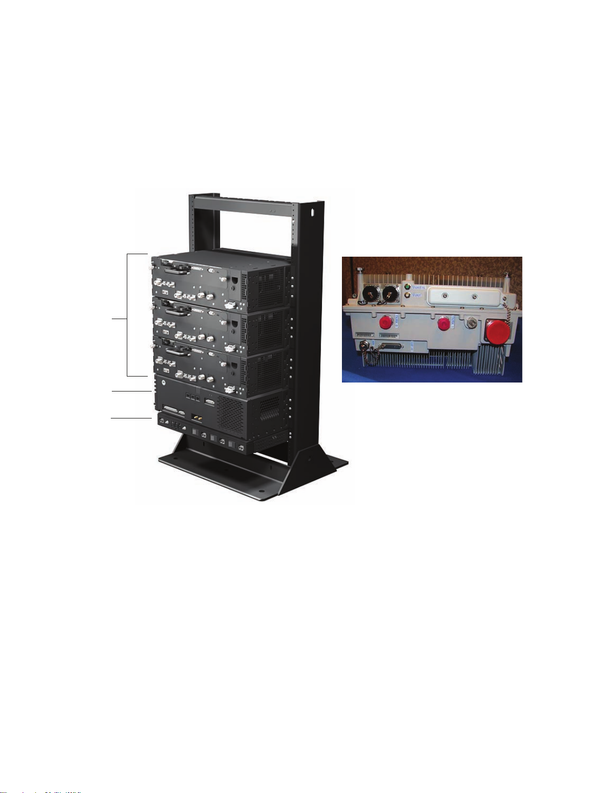
E1_majorcomponents_eNodeB.eps
3X
Radio Shelves
Remote Radio Head
BCUII
PDU
MajorComponentswithCall-outs
■■■■■■■■■■■■■■■■■■■■■■■■■■■■■■■■■■■■■■■■■■■■■■■■■■■■■■■■■■■■■
Figure1-1Majorcomponents
■
■
68P09308A55-61-5
FEB2010
Page 23

MajorComponentswithCall-outsChapter1:Introduction
Radio Fan Tray
Ground Lug
Power InputRF Filter
(behind front panel)
Figure1-2RadioFrameShelf
1-668P09308A55-6
FEB2010
Page 24

LTEeNodeBIndoorHardwareInstallationCongurationssupported
Congurationssupported
■■■■■■■■■■■■■■■■■■■■■■■■■■■■■■■■■■■■■■■■■■■■■■■■■■■■■■■■■■■■■
Thefollowingcongurationsaresupported:
Table1-2CongurationsSupported
■
■
FrameMounted
RemoteRadioHead
RemoteRadioHead
RemoteRadioHead
Radio
BCU
BCUII
BCUII
Power
Supply
+27Vdc
–48Vdc
FrequencyBand
700MHz
2.1GHz
CongurationT ype
Frame-basedeNodeB
RemoteRF-based
eNodeB
BCUII
–48Vdc
2.6GHz
RemoteRF-based
eNodeB
BCUII
–48Vdc
700MHz
RemoteRF-based
eNodeB
68P09308A55-61-7
FEB2010
Page 25

CongurationssupportedChapter1:Introduction
1-868P09308A55-6
FEB2010
Page 26

Chapter
2
Sitepreparation
■■■■■■■■■■■■■■■■■■■■■■■■■■■■■■■■■■■■■■■■■■■■■■■■■■■■■■■■■■■■■
■
■
■
■
68P09308A55-62-1
FEB2010
Page 27

OverviewChapter2:Sitepreparation
Overview
■■■■■■■■■■■■■■■■■■■■■■■■■■■■■■■■■■■■■■■■■■■■■■■■■■■■■■■■■■■■■
TheSitepreparationsectionprovidestheproceduresandinformationtoverifythatthesiteis
readytohavetheframesandotherequipmentinstalled.
Preparingthesiteforequipmentarrival
Basedonthesitecharacteristics,executethestepsthatapplytothesite.
Preparingtheoutdoorsitefortheequipment
Adetailedlayoutofthesiteisprovidedwiththesite-specicdocumentation.Beforeinstalling
thehardware,comparetheinformationpresentedheretothesite-specicdocumentationlayout
andverifythefollowingwiththesitemanager:
■
■
•Siteisclean.
•Site-specicdocumentationcoveringallsite-dependentinstallationinformationis
available.
•Theinstallationareahasrestrictedaccess.Equipmentismeanttobeinstalledand
operatedinarestrictedaccesslocation.
•Allbuilding/siteACorDCpowercablinghasbeeninstalled.
•Thescreen(outershield)oftheRFantennacoaxialcablemustbeconnectedtoearth
(grounded)attheentrancetothebuilding.Connectinggroundshouldbedonein
accordancewithapplicablenationalelectricalinstallationcodes(Section820.93ofthe
NationalElectricalCode,ANSI/NFP A70.
•Thisequipmentshallbeconnecteddirectlytothedcsupplysystemearthingelectrode
conductorortoabondingjumperfromanearthingterminalbarorbustowhichthedc
supplysystemearthingelectrodeconductorisconnected.
Thisequipmentshallbeconnecteddirectlytothedcsupplysystemearthingelectrode
conductorortoabondingjumperfromanearthingterminalbarorbustowhichthe
dcsupplysystemearthingelectrodeconductorisconnected.
Thisequipmentshallbelocatedinthesameimmediatearea(suchasadjacent
cabinets)asanyotherequipmentthathasaconnectionbetweentheearthed
conductorofthesamedcsupplycircuitandtheearthingconductor ,andalsothepoint
ofearthingofthedcsystem.Thedcsystemshallnotbeearthedelsewhere.
Thedcsupplysourceshallbelocatedwithinthesamepremisesasthisequipment.
Switchingordisconnectingdevicesshallnotbeintheearthedcircuitconductor
betweenthedcsourceandthepointofconnectionoftheearthingelectrodeconductor .
•VerifythattheMasterGroundBarisconnectedtoasolidearthground.Connectingthe
MasterGroundBarisrequiredtoensureprotectionfromhazardousvoltagesbyproviding
ahighintegrityprotectiveearthingcircuitwhentheframeislatergroundedtotheMaster
GroundBar.
2-268P09308A55-6
FEB2010
Page 28

LTEeNodeBIndoorHardwareInstallationPreparingthesiteforequipmentarrival
•Thesitecanmaintaintheoperatingtemperaturerange.
•ThebuildingmeetsthevoltageandamperagerequirementsshowninDCsupply
equipment,Maincircuitbreaker,andDCinputcableonpage2-7.
•Thesitecanmeetthechassisdimensions(asshowninLTEeNodeBComponentDimensions
onpage2-4)andnotviolateanyoftherequiredclearances(asshowninFigure2-1).
•TheDCsupplyequipment,Maincircuitbreaker ,andDCinputcablecalledoutinTable2-2
fortheLTEframeDCinputareeitherinstalledoravailabletobeinstalled.
•ThemountinglocationcansupporttheweightoftheLTEframeasstatedinT able2-1.
•TocomplywithUL/60950-1secondeditionsafetyrequirements,cablesconnectedtoAISG
andCustomerI/Omustbenomorethan42meters(140feet)andtheframeground
conductorsizemustbeaminimumof6AWG.
Procedure2-1Preparingtheoutdoorsitefortheequipment
1
2
Locatethedemarcationblocksforexternalutilities.
VerifythattheyareshownontheSiteEngineeringdocumentsanddetermine
therequiredcableroutingbacktotheequipmentframes.
Verifythefollowing:
•Availabilityofappropriateelectricalgroundconnectionsforthe
•Compliancewithanysiteengineeringdocumentationandspecications.
•DCpowerisavailableandmeetsthesitedocumentationspecications.
•Poleand/orwallmountingstructuresareadequate.Ensurethata
•Outdoorcablerunsareinstalledandmeetlocalbuildingcodes.
•Customerinputterminationtiepointsareavailable.
•Availabilityoflightingandpowerforinstallation.
Preparingtheindoorsitefortheequipment
equipment.
qualiedstructuralengineerveriestheRRHwallorpolestructureand
wall-mountorpole-mountinstallationfortheweightoftheinstallation
underadverseconditionsintheinstallationarea.
Performthefollowingsteps:
Procedure2-2Preparingtheindoorsitefortheequipment
1
68P09308A55-62-3
Locatethedemarcationblocksforinternalutilities.
Continued
FEB2010
Page 29

LTEeNodeBComponentDimensionsChapter2:Sitepreparation
Procedure2-2Preparingtheindoorsitefortheequipment(Continued)
VerifythattheyareshownontheSiteEngineeringdocuments,anddetermine
therequiredcableroutingbacktotheequipmentframes.
2
Verifythefollowing:
•Availabilityoflightingandpowerforinstallation.
•Availabilityofappropriateelectricalgroundconnectionsforthe
equipment.
•Accessto,androutingof;inputpower ,RFoutput,andgeneral
interconnectioncablingspace.
•DCpowerisavailableandmeetsthesitedocumentationspecications.
•LevelsurfaceandoorsupporttohandletheweightoftheeNodeB
equipment,frame,andcabling.
•Compliancewithanysiteengineeringdocumentationandspecications.
LTEeNodeBComponentDimensions
Table2-1showscomponentdimensionsforbothFrame-basedeNodeBandRemoteRF-based
eNodeBcongurations.
Table2-1L TEeNodeBcomponentdimensions
ItemDescription
STHN4146
STHN4121
STHN4120
STLN6905
STLN6906
SG1756BCUII48533013217.608.00311
STLN6903
19"Rack
19"Rack
19"Rack
Power
Distribution
Unit-+27V
dc
Power
Distribution
Unit-–48V
Radio/Duplexer
Shelf
Width
(mm)
53043092566.1430.0018
530430132577.1635.0027
5654301769125.6657.0037
485295448.824.0011
485295448.824.001
48533013217.648.0031to3
Depth
(mm)
Height
(mm)
Weight
(inlbs)
Mass
(inKg)
Height
(Rack
units)
Quantity
FrameRemote
EitherFrameor
Remote
—
—
1
—
Continued
2-468P09308A55-6
FEB2010
Page 30

LTEeNodeBIndoorHardwareInstallationFramedimensionsandclearances
NOTE
Table2-1L TEeNodeBcomponentdimensions(Continued)
ItemDescription
STFF4046
STWF4000
DualDuplexer
(UpperC
Band)
LTEIndoor
Radio(Upper
CBand)
2.6GHzRRH3251744094118.8
2.1GHzRRH3251894094319.8
700MHzRRH3462103444018.01to3
Framedimensionsandclearances
Figure2-1showsthefootprintoftherack.
Width
(mm)
2152906311.025.00
3563056014.336.50
Height,Width,Depthdimensionsdonotincludeconnectorsorcablesthatmaybe
attached.Thesedimensionsalsodonotincludetheremovalhandlesorthehinge.
Depth
(mm)
Height
(mm)
Weight
(inlbs)
Mass
(inKg)
Height
(Rack
units)
—
—
—
—
Quantity
1to3
1to3
—
—
1to3
1to3
68P09308A55-62-5
FEB2010
Page 31

FramedimensionsandclearancesChapter2:Sitepreparation
NOTE
Figure2-1Framedimensionsandclearances
Aninsulatingpadisattachedtothebaseoftheracktoelectricallyisolatetherack
fromtheoor.
2-668P09308A55-6
FEB2010
Page 32

LTEeNodeBIndoorHardwareInstallationElectricalRequirements
ElectricalRequirements
■■■■■■■■■■■■■■■■■■■■■■■■■■■■■■■■■■■■■■■■■■■■■■■■■■■■■■■■■■■■■
Cabinetvoltage
Therearetwobasicpowersystemtypes:
•RemoteRF-basedeNodeB:–48VdcRRH700MHz,2.1GHz,2.6GHz—forthistype,the
customercanusetheoptional–48VdcPDUfromMotorolaortheirowncircuitbreakers.
•Frame-basedeNodeB:+27Vdcframeradio700MHz—forthistype,the+27VdcPDU,
frameradios,andBCUIIareallco-locatedinthesamerack.
DCsupplyequipment,Maincircuitbreaker,andDCinputcable
■
■
TheDCsupplyequipment,maincircuitbreaker ,andDCinputcablesaredeterminedbythe
sitecharacteristics.
Table2-2WireAWG(min90Cinsulationrating)andcircuitbreakersizingfor+27V
dcframesystems
LTEFDD
LTEFrame
LTEFrame
LTEFrame
LTEFrame
LTEFrame
LTEFrame
LTEFrame
LTEFrame
LTEFrame
Numberof
Radios
Breakersize(A)
31753/0AWG16
21753/0AWG20
21502/0AWG16
21251/0AWG13
11753/0AWG29
11502/0AWG23
11251/0AWG18
11001AWG14
1902AWG11
Wiresize
(AWG)
Maximumcable
length(m)
68P09308A55-62-7
FEB2010
Page 33

DCsupplyequipment,Maincircuitbreaker ,andDCinputcableChapter2:Sitepreparation
Table2-3WireAWG(min90Cinsulationrating)andcircuitbreakersizingfor–48V
dcremoteRFbasedeNodeB(forsystemsusingtheMotorola-48VPDU)
LTEFDD
LTERRH
LTERRH
LTERRH
LTERRH
LTERRH
LTERRH
LTERRH
LTERRH
LTERRH
LTERRH
LTERRH
LTERRH
LTERRH
LTERRH
LTERRH
LTERRH
LTERRH
LTERRH
LTERRH
LTERRH
LTERRH
Numberof
Radios
31753/0AWG69
31502/0AWG
31502/0AWG
31251/0AWG44
31001AWG35
3902AWG27
3803AWG22
21753/0AWG89
21502/0AWG70
21251/0AWG56
21001AWG44
2902AWG35
2803AWG28
2704AWG22
11753/0AWG124
11502/0AWG98
11251/0AWG78
11001AWG62
1902AWG49
1803AWG39
1704AWG31
Breaker
size(A)
Wiresize(AWG)
Maximumcable
length(m)
55
55
2-868P09308A55-6
FEB2010
Page 34

LTEeNodeBIndoorHardwareInstallationSitegrounding
WireAWG(min90Cinsulationrating)andcircuitbreakersizingfor–48
VDCRRHsystemswithoutPDUoption(customer-providedPDUfunction)
ForBCUIIpowereddirectlyfromthe–48Vdcbranchcircuit,wherethePDUisoptional:
•BCUIIDCbranchcircuitprotection:Singlepole20Aratedcircuitbreakerfornominal
–48Vdc
•BCUIIDCcable:Customer-suppliedDCpowercable,VW-1#8–#10AWG,10m(32.8
feet),ULtemperaturerating105°C(167°F).
ForRRHpowereddirectlyfromthe–48Vdcbranchcircuit,wherethePDUisoptional:
•RRHDCbranchcircuitprotection:Singlepole30Aratedcircuitbreakerfornominal
–48Vdc.
•DCcable#1(branchcircuitbreakertobuildingI/Opoint):Customer-suppliedDCpower
cable,VW-1#8,10m(32.8feet)orless,ULtemperaturerating105°C(167°F).
•DCcable#2(buildingI/OpointtoRRH):MotorolasuppliedAB,asperTable2-4.
Sitegrounding
Sitegroundingisaccordingto
partnumber68P81150E62).
Grounding Guidelines for Cellular R adio Installations
(Motorola
68P09308A55-62-9
FEB2010
Page 35

EnvironmentRequirementsChapter2:Sitepreparation
EnvironmentRequirements
■■■■■■■■■■■■■■■■■■■■■■■■■■■■■■■■■■■■■■■■■■■■■■■■■■■■■■■■■■■■■
Operatingtemperaturerange
Theminimumairowclearancesfortheproductunderwhichitmustoperatethroughtheentire
temperaturerangewithatleastoneverticalfaceopenaredescribed.
Theoperatingtemperaturerangeisasfollows:
•OperatingT emperatureRange–Installtheequipmentinanenvironmentcompatiblewith
themaximumambienttemperatureoftheequipment.Theframe-basedeNodeBandindoor
componentsoftheremoteRFbasedeNodeBoperateoverthefollowingtemperature
rangeswithinthealtitudesshown:
-5ºCto+55ºCfrom-100mto1500m
-5ºCto+40ºCfrom1500mto3500m
■
■
-5ºCto+35ºCfrom3500mto4000m
TheLTERemoteRadioHeadoperatesoverthefollowingtemperaturerangeswithinthe
altitudesshown:
-40ºCto+55ºCfrom-100mto1500m
-40ºCto+40ºCfrom1500mto3500m
-40ºCto+35ºCfrom3500mto4000m
2-1068P09308A55-6
FEB2010
Page 36

LTEeNodeBIndoorHardwareInstallationCableRequirements
CableRequirements
■■■■■■■■■■■■■■■■■■■■■■■■■■■■■■■■■■■■■■■■■■■■■■■■■■■■■■■■■■■■■
Figure2-2andFigure2-3showthepowercablinganddatacablingfortheeNodeBsystem.
■
■
68P09308A55-62-11
FEB2010
Page 37

CableRequirementsChapter2:Sitepreparation
E1_SysPwrCabling1.eps
RACK
MGB
Rack
Customer
Supplied
Customer
Supplied
Customer
Power
+27 V
PDU
+27 V
Radio Shelf
Radio Shelf
Radio Shelf
BCU
AE
AC
AC
AC
AL
AL
**
**
When using a Motorola rack, only the BCU and the frame need to be cabled to the MGB.
When using a non-Motorola rack, all items must be cabled to the MGB.
RRH STYLE 1
MGB
Customer
Supplied
Customer
Supplied
Customer
Power
-48 V
PDU
-48 V
RRH
RRH
RRH
BCU
Surge suppressors
and filters
*
Building
Entrance/Exit
AE
AK
AK
AK
AB
AB
AB
AL
AL
*
Surge suppressors and filters are customer supplied.
MGB = Master Ground Bus
RRH STYLE 2
MGB
Customer
Supplied
Customer
Supplied
Customer
Power
-48 V
RRH
RRH
RRH
BCU
Surge suppressors
and filters
*
Building
Entrance/Exit
AB
AB
AB
AL
*
Surge suppressors and filters are customer supplied.
MGB - Master Ground Bus
Figure2-2SystemPowerCabling
2-1268P09308A55-6
FEB2010
Page 38

LTEeNodeBIndoorHardwareInstallationeNodeBCableDescriptions(min90Cinsulationrating)
E1_eNodeB_SysdataCable1.eps
RRH
Customer
Termination
Customer I/O
Ethernet
BCU
Fiber Optic
RFGPS
AM
AA
RRH
RRH
RRH
Customer
Supplied
Antenna
RF
AA
AA
AG
AN
Customer
Supplied
Antenna
RF
Customer
Supplied
Antenna
RF
RACK
Customer
Termination
Customer I/O
Ethernet
BCU
Fiber Optic
RFGPS
AM
AD
AF
*
*
Cable AF connects RF signal between the
TRANSMIT OUT and TX on the Radio Shelf.
Radio Shelf
AF
*
Radio Shelf
AF
*
Radio Shelf
Customer
Supplied
Antenna
RF
AD
AD
AG
AN
Customer
Supplied
Antenna
RF
Customer
Supplied
Antenna
RF
Building
Entrance/Exit
Building
Entrance/Exit
Figure2-3SystemDataCabling
eNodeBCableDescriptions(min90Cinsulationrating)
68P09308A55-62-13
Table2-4eNodeBCableDescriptions
Cablelabel
AA
PartnumberDescriptionWhereused
SYKN8904
SYKN8905
SYKN8906
SYKN8907
SYKN8908
SYKN8909
6m(19.68ft),FiberOpticCable
20m(65.6ft),FiberOpticCable
40m(131.2ft),FiberOpticCable
60m(196.8ft),FiberOpticCable
80m(262.4ft),FiberOpticCable
100m(328.0ft),FiberOpticCable
RemoteBasedeNodeB
Continued
FEB2010
Page 39

eNodeBCableDescriptions(min90Cinsulationrating)Chapter2:Sitepreparation
Table2-4eNodeBCableDescriptions(Continued)
Cablelabel
AB
ACSTKN4129
AD
AE
AF
AGSGKJ4000
AH
AI
AK
AL
AM
AN
PartnumberDescriptionWhereused
SYKN8859
20m(65.6ft),8AWG—RRHDC
RemoteBasedeNodeB
PowerCable(105Crated)
SYKN8860
6m(19.68ft),10AWG—RRHDC
PowerCable(105Crated)
SYKN8864
40m(131.2ft),8AWG—RRHDC
PowerCable(105Crated)
SYKN8863
60m(196.8ft),6AWG—RRHDC
PowerCable(105Crated)
SYKN8862
80m(262.4ft),6AWG—RRHDC
PowerCable(105Crated)
SYKN8861
100m(328.0ft),6AWG—RRHDC
PowerCable(105Crated)
RadioPowerCables—PwrCableto
frame-basedeNodeB
connectRadioShelftoPDU
STKN4134
RadioFiberCables/Transceivers—
frame-basedeNodeB
3-footbercablewithtwooptical
transceiversusedtointerconnectthe
BCUtoeachRFRadio
STKN4128
BCUIIPowercableframe-basedeNodeB,
RemoteBasedeNodeB
STKN4130
RadioRFCables—Transmitcable
frame-basedeNodeB
fromtheradiotothelter/duplexer
50-FootGPSCable—50-F ootRFGPS
Cable
T472AC
76m(250ft),RGPScable—Includes
receiverandcablesinpre-cutlengths
T472AE
304m(998ft),RGPScable—Includes
receiverandcablesinpre-cutlengths.
Customer
DCpowercable,VW-1#8–#10AWG,
frame-basedeNodeB,
RemoteBasedeNodeB
frame-basedeNodeB,
RemoteBasedeNodeB
frame-basedeNodeB,
RemoteBasedeNodeB
RemoteBasedeNodeB
10m(32.8ft),ULtemperaturerating
105°C(167°F).
3088961T10
Powercable,femaleconnectoron
RemoteBasedeNodeB
oneendwithtwowiresontheother
end,1000mm+/-200mm,2stranded
cables/wires(blackandred),8AWG
Customer
CGDS19797321
Groundcable,6AWG,lengthneed
determinedbysiteconguration
CustomerI/Ocable,partofSGLN8484,
connectorononeendandloosewires
frame-basedeNodeB,
RemoteBasedeNodeB
frame-basedeNodeB,
RemoteBasedeNodeB
ontheother
Customer
Ethernet,RJ45connectors,
straight-through,shieldedCAT5e,90
frame-basedeNodeB,
RemoteBasedeNodeB
m,max.24AWGsolidconductor
2-1468P09308A55-6
FEB2010
Page 40

LTEeNodeBIndoorHardwareInstallationToolsrequiredforinstallingtheeNodeBcomponents
ToolsrequiredforinstallingtheeNodeBcomponents
■■■■■■■■■■■■■■■■■■■■■■■■■■■■■■■■■■■■■■■■■■■■■■■■■■■■■■■■■■■■■
ThefollowingtoolsarerequiredtoperformtheinstallationofeNodeBcomponents:
Torquewrenches:
•SMATorqueWrench
•TypeNconnectortorquewrench
•Torquedrivercapableofdrivingbits1.1N-m(10in-lb),1.3N-m(12in-lb),1.8N-m(16
in-lb),4.7N-m(42in-lb),and5.1N-m(45in-lb)
•Torquedrivercapableoftorquing10mmsocketto5.1N-m(45in-lb)
Bitdriverandbits:
•Bitdriver
•T15Torxbit
■
■
•T20Torxbit
•T25Torxbit
•T30Torxbit
•T20Torxsecuritybit
•T30Torxsecuritybit
•Flatbladescrewdriverbit
Generaltools:
•10mmsocket
•13mmsocket(toinstallM8nutsonRRH)
•19mmsocket(forM12bolts)
•3-inchsocketextension
•10mmnutdriver
•Wirestrippers
•Cableinsulationstrippingtool(example:Greenlee1900)
Recommendedtools:
•Sidecutters
•6-inchbitdriverextension
68P09308A55-62-15
FEB2010
Page 41

ToolsrequiredforinstallingtheeNodeBcomponentsChapter2:Sitepreparation
2-1668P09308A55-6
FEB2010
Page 42

Chapter
3
Frame-basedeNodeBInstallation
■■■■■■■■■■■■■■■■■■■■■■■■■■■■■■■■■■■■■■■■■■■■■■■■■■■■■■■■■■■■■
Theproceduresdescribedinthischapterrelatetotheframe-basedeNodeBsystemwhichis
+27Vdconly.
■
■
■
■
68P09308A55-63-1
FEB2010
Page 43

OverviewChapter3:Frame-basedeNodeBInstallation
Overview
■■■■■■■■■■■■■■■■■■■■■■■■■■■■■■■■■■■■■■■■■■■■■■■■■■■■■■■■■■■■■
•OperatingTemperature–Operatingtemperaturerangeonpage2-10.Installtheequipment
inanenvironmentcompatiblewiththemaximumambienttemperatureoftheequipment.
•ReducedAirFlow–Installtheequipmentintheracksuchthattheamountofairow
requiredforsafeoperationoftheequipmentisnotcompromised.
•MechanicalLoading–Mounttheequipmentintheracktopreventahazardouscondition
duetounevenmechanicalloading.
•CircuitOverloading–Useappropriateequipmentnameplateratingswhenconnectingthe
equipmenttothesupplycircuit.Considertheeffectthatoverloadingofthecircuitsmay
haveonovercurrentprotectionandsupplywiring.
•ReliableGrounding–Groundingoftherack-mountedequipmentmustbereliable.Pay
attentiontothesupplyconnectionsotherthanthedirectconnectionstothebranchcircuit
(forexample,useofpowerstrips).
■
■
PlanthelocationoftheLTEeNodeBsystemwithintherack.
3-268P09308A55-6
FEB2010
Page 44

LTEeNodeBIndoorHardwareInstallationOverview
E1_majorcomponents_eNodeB.eps
3X
Radio Shelves
BCUII
PDU
Figure3-1Indoorsystem
68P09308A55-63-3
FEB2010
Page 45

OverviewChapter3:Frame-basedeNodeBInstallation
Radio Fan Tray
Ground Lug
Power InputRF Filter
(behind front panel)
Figure3-2RadioFrameShelf
3-468P09308A55-6
FEB2010
Page 46

LTEeNodeBIndoorHardwareInstallationUnpackingEquipment
UnpackingEquipment
■■■■■■■■■■■■■■■■■■■■■■■■■■■■■■■■■■■■■■■■■■■■■■■■■■■■■■■■■■■■■
Verifythecontentsofallshipmentsforcompleteness,accuracy ,andserviceabilityofall
componentsbeforeinstallation.Theequipmentisshippedwithapackinglist,listingallthe
partsshipped.Onreceivingtheequipment,checkthepackinglisttoverifythatallitemsare
received.Checkallcablesfordamageandallhardwareforscratchesanddents.Download
orretrievetheappropriatedocumentationtoinstalltheproduct.ContactMotorolaifany
discrepancyexistsbetweenthepackinglistandthedeliveredmaterial.
■
■
68P09308A55-63-5
FEB2010
Page 47

InstallationoftherackChapter3:Frame-basedeNodeBInstallation
Installationoftherack
■■■■■■■■■■■■■■■■■■■■■■■■■■■■■■■■■■■■■■■■■■■■■■■■■■■■■■■■■■■■■
TheInstallationoftheracksectionprovidesprocedurestoinstallandgroundtherack.
Rackandgroundcableinstallation
TheRackandgroundcableinstallationsectionprovidestheproceduretomountthestandard
19-inchracktotheoorandinstallthegroundcable.
TheL TEsystemcanbeinstalledina19-inchracksuppliedbyMotorolaoracustomer-supplied
rack.TheMotorolarackisrecommended,asitensuresthatthepropergroundpathisachieved
throughchassisgroundsthroughthePDUandRadioFilterShelfmechanicswithouttheuseof
separategroundcables.Ifanon-Motorolarackisused,agroundcablemustbeusedforeachof
thesecomponentsplustheBCUII,whichrequiresagroundcablewithanyracktype.
Aninsulatingpadisattachedtothebaseoftheracktoelectricallyisolatetherackfromtheoor .
■
■
Structuralengineerprerequisite
Requireditems
Ensurethattheprocedure,tools,andequipmentrequiredtomounttheracktotheoorare
speciedbyaStructuralEngineer .
Thefollowingitemsarerequired:
•Rack
•10mmsocket
•19mmsocket
•6plasticshoulderwashers
•Torquedriver
•Crimpertool-AndersonPowerProductspartnumber1368-Hydraulichandtool,maximum
cablesizeof300MCM.
•6carbonsteelgrade8.8boltsM12orotherboltsasdeterminedbystructuralengineer-
customersupplied.
•Otheritems,speciedbythestructuralengineer ,thatarerequiredtoinstalltherack.
•Customersuppliedgroundcable,6AWGorlargerdiameter .
•Two-holegroundlugandmountingnuts-partofrackhardwarekit.
3-668P09308A55-6
FEB2010
Page 48

LTEeNodeBIndoorHardwareInstallationRackandgroundcableinstallation
NOTE
NOTE
Installingrackandgroundcable
PerformthestepsinProcedure3-1toinstalltherackandgroundcable.
Procedure3-1Installingrackandgroundcable
1
2
3
4
5
6
7
Mounttheracktotheoorusingthehardware,tools,andproceduresdened
bythestructuralengineer .
Motorolarecommendsusingcarbonsteelgrade8.8M12bolts.
RoutethegroundcablebetweentheMasterGroundBar(MGB)andtherack.
Groundcablesmustnothavesharpbends.
Stripinsulationfromtheframeendofthegroundcable.
Attachthe2-holelugtotherack-endofthegroundcable.
Eitherusetheappropriatecrimpingtoolorsolderthelugtothecable.
Attachtheendofthegroundcablewiththe2-holelugtothetwoterminal
studsatthetopoftherack.Using2nuts,10mmsocketandratchet,tighten
thenutsto5.1N-m(45in-lb).
RefertoFigure3-3forlocationofgroundterminalstudsontherack.
CutthegroundcabletolengthandconnectittotheMasterGroundBar .
VerifythattheMasterGroundBarisconnectedtoasolidearthground.
68P09308A55-63-7
FEB2010
Page 49

RackandgroundcableinstallationChapter3:Frame-basedeNodeBInstallation
Earth Ground
Terminal Studs
Ground Cable With
2-hole Lug Fastened
To Ground Terminals
Rack
(top/rear view, shown
partially cut away)
Figure3-3LocationofgroundterminalsonaMotorolarack
3-868P09308A55-6
FEB2010
Page 50

LTEeNodeBIndoorHardwareInstallationInstallingthe+27Vdc(PDU)
NOTE
NOTE
Installingthe+27Vdc(PDU)
■■■■■■■■■■■■■■■■■■■■■■■■■■■■■■■■■■■■■■■■■■■■■■■■■■■■■■■■■■■■■
TheInstallationofthePowerDistributionUnit(PDU)sectionprovidestheproceduretoinstall
thePDU.
Theconnecting+27Vdcpowersectionprovidesthefollowinginformation:
•Attachingthecontact/lugs,connector ,andcableclamponthe+27Vdcpowerinputcable
wires.
•Connectingthe+27VdcinputpowercabletotherearofthePDU.
•Routingthelooseendsofthewirestothesite+27Vdcsourceforconnection.
Requiredmaterialsandtools
■
■
Thefollowingmaterialsandtoolsarerequired:
•One+27VdcPowerInputCable(DC)-customersupplied.
•Crimptoolappropriateforwiresizeandlugbeingused.
•Wirestripper/cutters.
•DigitalMulti-Meter(DMM)FlukeModel8062AwithY8134testleadkitorequivalent;used
InstallingthePDU
PerformthefollowingproceduresintoinstallthePDUinthe19-inchrack.
Procedure3-2AdjustingMountingEars
MotorolarecommendstheuseofRedwireforfeed(+V)andBlackwirefor
return(-V).
forprecisionDCandACmeasurements,requiring4-1/2digits.
1
Use+27VdcpowerPDUwiththepartnumberSTLN6905
Continued
68P09308A55-63-9
FEB2010
Page 51

InstallingthePDUChapter3:Frame-basedeNodeBInstallation
NOTE
NOTE
NOTE
Procedure3-2AdjustingMountingEars(Continued)
2
PerformthefollowingproceduretoinstallthePDU.
Adjustthesideearsasfollows:
ThePDUandallotherLTEframeequipmentcanbemountedinto
therackinaforwardorrearwardposition.ThePDU,BCUII,and
RadioFilterShelfareprovidedwithmountingearsinstalled,so
thatthesecomponentsareintheforwardpositionintherack.
Ifdesired,themountingearscanbechanged,sothePDUresidesintherear
positionwithintherack.
1.DisassembletheleftandrightmountingearsfromthePDUsidebrackets
usingaT20driver .
2.ReinstalltheleftandrightmountingearsonthePDUsidebracketat
thefrontpositionusingaT20driver.TorquetheM4screwsto1.8N-m
(16in-lb).
Procedure3-3MountingPDUintoRack
1
2
PerformthefollowingproceduretogroundthePDU.
MountthePDUintothe19-inchrackasfollows:
UsethescrewsprovidedwiththePDU.Ifotherscrewsaretobeused,then
obtainfourscrewswhichareatleast10mm(3/8inch)long.
TheM5screwsareattachedinabagtotherearbracket.
MountthePDUinthebottommostRackUnit.Installtwoscrewsperside
usingaT25Torxbitandtorqueto4.7N-m(42in-lb).
Procedure3-4GroundingPDU
1
Performthissteponlyifanon-Motorolarackisused.19-inchracks
thatarepaintedonthe19-inchmountingrailfrontfacerequire
anexternalPDUgroundcable.
Continued
3-1068P09308A55-6
FEB2010
Page 52

LTEeNodeBIndoorHardwareInstallationInstallingthePDU
NOTE
NOTE
Procedure3-4GroundingPDU(Continued)
ThePDUissuppliedwith2-holecrimplugsfor1/0AWGstandard
or2AWGhigh-strandcountexwire.Ifanothertypeofcableis
required,orderanewlugasneeded.Thenewlugandgroundcable
mustequalthesizedeterminedfortheDCInputCablesinthe
precedingsteps.EnsurethatthelugmeetsthecriteriainTable3-2.
Theexpectedloadconditionandcablelengthdeterminesthewire
gaugerequiredforyoursystem.SeeTable2-2.
2
3
4
PerformthefollowingproceduretoconnectpowertothePDU .
Crimpthetwo-holelugontotheGroundCable.
InstallthelugontothePDURearBracket.SecurethelugwithtwoM6Nylock
nutstorquedto5.1N-m(45in-lb).
CutthegroundcabletolengthandconnectittoMasterGroundBar .
Procedure3-5ConnectthePDUtopower
1
2
3
4
5
6
EnsurethatthegroundcableisconnectedbetweentherackandtheMaster
GroundBar.
Ensurethatthe+27VdcPowerInputCable(DC)isnotconnectedtothemain
+27Vdcpowersource.
Turnoffthemain+27Vdcpowersource.
ConrmthatthepowerisswitchedOFFusingaDVM.
ThePDUissuppliedwith2-Holecrimponlugsfor1/0AWGstandardor2
AWGhigh-strandcountexcable.Ifyourequireanothertypeofcable,order
newlugsasneeded.EnsurethatthelugsmeetthecriteriainT able3-2
Theexpectedloadconditionandcablelengthdeterminethewire
gaugerequiredforthesystem.SeeTable2-2.
Removethelugcoverandservicecoverusingtheirrespectivesnaps.
Insertthetwo-holelugsthroughtherearofthePDU ,sothattheholesinthe
lugsalignwiththeholesinthelugmountingplates.
InstalltwoM6atwashersandtwoM6x16screwsintoeachlug(4washers
and4nutstotalforthe2lugs)usingaT30Torxdriver .
Theatwashersandscrewsaresuppliedinthebagsziptiedtothe
PDUrearbracket.
Leavethescrewsloosesothatthelugscanbeadjustedside-to-side.
Continued
68P09308A55-63-11
FEB2010
Page 53

InstallingthePDUChapter3:Frame-basedeNodeBInstallation
NOTE
ti-cdma-05694.eps
Procedure3-5ConnectthePDUtopower(Continued)
7
8
9
10
Replacethelugcoverwhileadjustingthecablestoensurethatthecover
canbesnappedintoposition.
Tightenthelugscrewsto5.1N-m(45in-lb)andreplacetheservicecover .
Installziptiesaroundthecablesthroughtherearbracketandpulltightfor
sufcientstrainrelief.
Connecttheotherendofthe+27Vdcpowerandreturnwirestothepower
source.
Figure3-4PDUpowerconnection
Donotturnonthepowersourceatthistime.Thismustbedone
aftertheinstallationandcablingiscomplete.
3-1268P09308A55-6
FEB2010
Page 54

LTEeNodeBIndoorHardwareInstallationInstallingthePDU
PDU front.eps
Table3-1Frame-basedeNodeBcableconnectionstoPDUbreakers
Connector
BKR1BCUII
BKR2A
BKR2B
BKR2C
BKR3
BKR4
BKR5
Figure3-5PDUFront
Load
AuxiliaryEquipment#1
AuxiliaryEquipment#2
AuxiliaryEquipment#3
RadioSector1
RadioSector2
RadioSector3
Table3-2Lugcriteria
PDUinput
LTEPDUinput
labeltext
+27Vdc(red
+27Vdc
arrow)
0V(blackarrow)16mm(5/8inch)
GroundFrameground16mm(5/8inch)
Crimplug'scenter–to
–centerspacingofM6
(1/4”)screwholes
19mm(3/4inch)
Wiregaugecompatibility
forsuppliedlugs
1/0standardcable
68P09308A55-63-13
FEB2010
Page 55

InstallationoftheBCUIIChapter3:Frame-basedeNodeBInstallation
ti-cdma-05694.eps
InstallationoftheBCUII
■■■■■■■■■■■■■■■■■■■■■■■■■■■■■■■■■■■■■■■■■■■■■■■■■■■■■■■■■■■■■
TheInstallationoftheBCUIIsectionprovidesgeneralinformationandproceduresforinstalling
aBaseControlUnitII(BCUII).
BCUIIisdesignedasanindoorcomponentthatcanbemountedonastandard19-inchrack.
Figure3-6showstheBCUII.
Figure3-6BCUIIphysicaldesign
■
■
Requiredmaterialsandtools
Thefollowingmaterialsandtoolsarerequired:
•BCUIISG1756
•T15driver
•T10driver
•T25torxbit
•10mmsocket
•Customersuppliedgroundcable,lengthdeterminedbydistancefromtheunittothe
masterground.
3-1468P09308A55-6
FEB2010
Page 56

LTEeNodeBIndoorHardwareInstallationBCUIIinstallation
NOTE
NOTE
•Wirestripper/cutters.
•DigitalMulti-Meter(DMM)FlukeModel8062AwithY8134testleadkitorequivalent;used
forprecisionDCandACmeasurements,requiring4-1/2digits.
BCUIIinstallation
Procedure3-6AdjustingMountingEars
1
Adjustthesideearsasfollows:
TheBCUIIandallotherLTEframeequipmentcanbemountedinto
therackinaforwardorrearwardposition.ThePDU,BCUII,and
RadioFilterShelfareprovidedwithmountingearsinstalled,so
thatthesecomponentsareintheforwardpositionintherack.
Ifdesired,themountingearscanbechanged,sotheBCUIIresidesinthe
rearpositionwithintherack.
1.DisassembletheleftandrightmountingearsfromtheBCUIIside
bracketsusingaT10driver.
2.ReinstalltheleftandrightmountingearsontheBCUIIsidebracketat
thefrontpositionusingaT10driver .TorquetheM3screwsto1.12
N-m(10in-lb).
Leftmountingeargoestotherightsideandtherightmounting
eargoestotheleftside.
PerformthestepsinProcedure3-7toinstallpowercablestotheBCUII.
Procedure3-7CablingPowertoBCUII
1
2
3
68P09308A55-63-15
Stripeachwire12.7mm(1/2inch).
InsertwiresaccordingtothecolorcodeonthebackoftheBCUII.Tighten
thescrewsto1.3N-m(12in-lb).SeeFigure3-7.
Plugtheblack2-pinconnectorintothefrontofthePDUBrkr1.
Routethecablewiththegreenscrewterminalconnectortowardstherear
overtheleftmountingear .
Continued
FEB2010
Page 57

BCUIIinstallationChapter3:Frame-basedeNodeBInstallation
NOTE
-27V.eps
Procedure3-7CablingPowertoBCUII(Continued)
4
5
Threadthecablethroughtheslotintheleftsidebracketjustbehindthe
plastichousingandacrosstherearofthePDU.
InstalltheBCUIIintherack.
ThepowercablemustbepluggedintoBCUIIduringtheBCUII
installationprocedure.
Figure3-7CablingPowerto+27VdcBCUII
PerformthestepsinProcedure3-8toinstalltheBCUII.
Procedure3-8BCUIIInstallation
1
2
3-1668P09308A55-6
PlacearackmountingscrewinthefthholeabovethePDUrightearbracket.
LeavethescrewheadspacedoutfromtherackfacetoallowfortheBCUII
mountingeartobeinstalledoverthescrewhead.
PlacearackmountingscrewinthefthorsixthholeabovethePDUleftear
bracket.Leavethescrewheadspacedoutfromtherackfacetoallowthe
BCUIImountingeartobeinstalledoverthescrewhead.
Continued
FEB2010
Page 58

LTEeNodeBIndoorHardwareInstallationBCUIIinstallation
NOTE
Procedure3-8BCUIIInstallation(Continued)
3
4
ConnectingGroundtoBCUII
PerformthestepsinProcedure3-9toconnectthegroundcabletoBCUII.
Procedure3-9ConnectinggroundtoBCUII
1
2
3
4
HangtheBCUIIonthetwomountingscrewsandmatethegreentwo-position
ScrewT erminalConnectorintotheBCUIIPowerSupplyontherear.
Tightenthetworetainingscrewsintothematingconnectorto1.3N-m(12
in-lb.
UseaT25torxbittoinstalltheremaining(twoscrewsperside)rackmounting
screws.Torqueallrackmountingscrewsto4.7N-m(42in-lb).
Removethegroundlugfromtheleftinsidewallusinga10mmsocketor
nutdriver.
CrimptheBCUIIgroundlugontoa6AWGwire.
Attachthegroundwiredoubleholelugtothethreadedstudslocatedatthe
BCUIIcardcagefrontleftcorner.
SecurethegroundwirelugtothethreadedstudswiththetwoM6nuts.Using
a10mmsocketandtorquedriver ,tightenthenutsto5.1N-m(45in-lb).
Connecttheotherendofthegroundwiretothemastergroundbar .
Donotreinstallbercover(feedthroughplate)atthistime.Setit
asideforsafekeepinguntiltheberinstallationiscompletedlater .
68P09308A55-63-17
FEB2010
Page 59

BCUIIinstallationChapter3:Frame-basedeNodeBInstallation
Fiber Cover
Ground Lug
2X Screws
See Detail A
Detail A
D2_GNDLgFbrCvr_InDrBCUII
Figure3-8BCUIIGrounding
3-1868P09308A55-6
FEB2010
Page 60

LTEeNodeBIndoorHardwareInstallationInstallationofRadio/FilterShelf(RFS)andFrameMountedRadioHead
FRONT VIEW
LTE_shelf_frt.eps
0V
+27V
TRANSMIT STATUS
TRANSMIT
OUT 0
KIT
NUMBER
SERIAL
NUMBER
TX-1
TX/RX-0
LTE
FWD REF
VSWR
TX-0
TX/RX-1
FWD REF
MODULE STATUS
CONTROL
PROCESSOR
TRANSMIT
OUT 1
D4+0
D4+1
D4+0
ENET
D4+1
VSWR
+27V
0V
GND
TX/RX-0 TX -0FWD REF
TX/RX-1 TX -1
FWD REF
FAN TRAY
TRANSMIT
STATUS
MODULE
STATUS
CONTROL
PROCESSOR
ENET
TRANSMIT
OUT 1
TRANSMIT
OUT 0
D4+0
D4+0
LED
D4+1
LED
D4+1
CABLE
CLIP
CABLE
CLIP
InstallationofRadio/FilterShelf(RFS)andFrame
MountedRadioHead
■■■■■■■■■■■■■■■■■■■■■■■■■■■■■■■■■■■■■■■■■■■■■■■■■■■■■■■■■■■■■
Figure3-9Radio/FilterShelf
■
■
ThissectionprovidestheproceduretoinstalltheRadio/FilterShelf(RFS).
Thefollowingmaterialsandtoolsarerequired:
•RFSSTLN6903
•RFHeadSTWF4000
•Customersuppliedgroundcable,lengthdeterminedbydistancefromtheunittothe
masterground(requiredonlyifnotusingtheMotorolaprovidedrack).
•T20Torxbit
•10mmsocket
•T25Torxbit
•Wirestripper/cutters
68P09308A55-63-19
FEB2010
Page 61

InstallationofRadio/FilterShelf(RFS)andFrameMountedRadioHeadChapter3:Frame-basedeNodeBInstallation
PerformthefollowingproceduretoinstalltheRFSDuplexer .
Procedure3-10InstallingRFSDuplexer
1
2
3
4
5
MovethetwoRFcablesoutoftheway .InserttheDuplexerintotheRFS.
PulltheDuplexertowardsthefront,sotheDuplexerbodyrestsagainstthe
insidefrontfaceoftheRFSchassis.
UsingaT20T orx,screwtwoM4screwsthroughthefrontfaceoftheRFSinto
theDuplexerbody .T orqueto2.25N-m(20in-lb).
Witha10mmsocketand3-inchsocketextension,securetheDuplexerto
thetwoM6studsinthebottomoftheRFSshelfwithtwoM6nuts.Torque
to5.1N-m(45in-lb).
MatethetwoRFcablesattherearoftheDuplexer .Ensurethatthecable
bendsarenolessthan6mm(1/4inch)radius.
Figure3-10InstallingDuplexer
TheRFScanbemountedintotherackinaforwardorrearwardposition.TheRFSisprovided
withthemountingearsinstalledsothatitisintheforwardpositionintherack.
3-2068P09308A55-6
FEB2010
Page 62

LTEeNodeBIndoorHardwareInstallationInstallationofRadio/FilterShelf(RFS)andFrameMountedRadioHead
NOTE
NOTE
NOTE
Procedure3-11AdjustingMountingEars
1
UseRFSwiththepartnumberSTLN6903.
2
Adjustthesideearsasfollows:
TheRadioFilterShelfandallotherLTEframeequipmentcanbe
mountedintotherackinaforwardorrearwardposition.ThePDU ,
BCUII,andRFSareprovidedwithmountingearsinstalled,sothat
thesecomponentsareintheforwardpositionintherack.
Ifdesired,themountingearscanbechanged,sotheRFSresidesintherear
positionwithintherack.
1.DisassembletheleftandrightmountingearsfromtheRFSsidebrackets
usingaT20driver .
2.ReinstalltheleftandrightmountingearsonthePDUsidebracketat
thefrontpositionusingaT20driver .TorquetheM4screwsto2.25
N-m(20in-lb).
Theleftmountingeargoestotherightsideandtherightmounting
eargoestotheleftside.
Procedure3-12InstallingRFS
1
2
3
Forboththeleftandrightsideofthe19-inchrack,installonerackmounting
screwinthefthholeabovetheBCUIIMountingEarBracket.Leavethe
screwheadspacedoutfromtherackfacetoallowtheBCUIIMountingEar
tobeinstalledoverthescrewhead.
WiththeRFSorientedsothattheDuplexeristowardsthebottom,installthe
RFSsothatthecenterkeyholeintheSideMountingBracketslipsoverthe
rackmountingscrewsinstalledinstep1.
SecuretheRFStotherack.UseaT25T orxbittoinstalltheremainingrack
mountingscrewsto4.7N-m(42in-lb).
68P09308A55-63-21
FEB2010
Page 63

RFSpowercableinstallationChapter3:Frame-basedeNodeBInstallation
PerformthefollowingproceduretoinstalltheF ameMountedRadioHead.
Procedure3-13InstallingFrameMountedRadioHead
RFSpowercableinstallation
1
2
OnepowercableisrequiredperRFS.
PerformthestepsinProcedure3-14toinstalltheDCpowercabletotheRFS.
WiththeRadioorientedwiththehandletotheleft,slidetheRadiointothe
RFSuntilfullyseated.
UsingaT20Torx,screwthetwoblackthumbscrewsonthefrontoftheRadio
intotheRFS.Torqueto2.25N-m(20in-lb).
Procedure3-14InstallingRFSpowercable
1
2
PlugtheRFScablesintothePDUbreakers4,5,and6.Maketheconnections
pertheinformationinTable3-1,wheresector1isthebottom-mostRFSinthe
frame.
Installcabletiebracketstotheradioltershelf(snapinplace).Usezipties
totiethepowercablestothecabletiebracketsasshowninFigure3-11.
3-2268P09308A55-6
FEB2010
Page 64

LTEeNodeBIndoorHardwareInstallationRFSGroundCableInstallation
NOTE
Figure3-11T yingpowercablestothecabletiebrackets
RFSGroundCableInstallation
PerformthestepsinProcedure3-15toaddanexternalgroundcabletotheRFS.
ExecuteProcedure3-15onlyiftherackisnotaMotorolarack.TheMotorolarackhas
nopaintonthe19-inchmountingrailfrontface.Groundcurrentcantravelthrough
thePDUchassistotheframegroundlug.Other19-inchracksthathavepaintonthe
19-inchmountingrailfrontfacerequireanexternalRFSgroundcable.
68P09308A55-63-23
FEB2010
Page 65

RFSGroundCableInstallationChapter3:Frame-basedeNodeBInstallation
NOTE
M6 Nuts
Procedure3-15InstallingRFSgroundcable
1
2
3
Crimpthe2–holecrimplugontothecustomersuppliedgroundcable.
InstallthelugontotheRFS.
Usinga10mmsocketanddriver,securethelugwith2M6nutstorqued
to5.1N-m(45in-lb).
Figure3-12RFSgroundcableconnection
TheRFSissuppliedwith2-holecrimplugsfor6AWGstandard
wire.
3-2468P09308A55-6
FEB2010
Page 66

LTEeNodeBIndoorHardwareInstallationInstallationoftheGPS
CAUTION
InstallationoftheGPS
■■■■■■■■■■■■■■■■■■■■■■■■■■■■■■■■■■■■■■■■■■■■■■■■■■■■■■■■■■■■■
InstallingRFGPSantennaandcable
Figure3-13showsthecomponentsoftheRFGPS(RFGPS).
WhenmountingtheRFGPSAntennaconsiderthefollowingitems:
•ThemountingpipefortheRFGPSheadismountedverticallywithlessthanve(5)
degreesoftilt.
•TheRFGPSheadrequiresaclearviewofthesky,preferablywithinten(10)degreesofthe
horizoninalldirections.
•Themoreskythatisobservedincreasesthenumberofpotentialsatellitesthatcanbe
tracked,resultinginbetterRFGPSperformance.
■
■
•Duringnormaloperation,theRFGPSheadcontinuouslytracksaminimumoffour(4)
GPSsatellites.However,itistheoreticallypossibletooperatetheBTSbytrackingonly
one(1)GPSsatellite.Motoroladoesnotrecommendtrackingonlyone(1)GPSsatellite
unlesstherehasbeenanaccuratesitesurvey.
•PlacetheRFGPSheadwhereRFobstructionsoftheskyareminimal.Theskyincludes
everythingwithinten(10)degreesofthehorizoninalldirections.RFobstructionsinclude
buildings,towers,naturalrockformations,snow ,foliage,anddebris.
PerformthefollowingproceduretoinstalllocalGPS(RFGPS):
Procedure3-16InstallingRFGPSantennaandcabling
1
2
3
4
DeterminethelocationfortheRFGPSSurgeProtectiondevice(preferablyat
theentrancetothebuilding).
ConnecttheRFGPSSurgeProtectiondevicetothemastergroundbus(MGB).
Determinethemountinglocation.
Ensurethataqualiedstructuralengineerveriestheroofstructure
onwhichthemountingpoleisattachedfortheweightoftheRFGPS
engineandmountinghardwareunderadverseconditionsinthe
installationarea.
68P09308A55-63-25
InstallthemountingkitattheRFGPSlocation.Usetheappropriatemounting
boltsformountingsurface.
Continued
FEB2010
Page 67

InstallingRFGPSantennaandcableChapter3:Frame-basedeNodeBInstallation
Procedure3-16InstallingRFGPSantennaandcabling(Continued)
5
AttachtheRFGPSantennaassemblytothemountingbracketandsecurethe
washerandcustomnutsupplied.SeeFigure3-13.
6
AttachthegroundingkittothemountingpolewithU-boltsandsecureusing
thewashersandnutssupplied.SeeFigure3-13.
7
ConnecttheNconnectorofthe50ft(15.24m)superexcabletotheRFGPS
antennacable.
8
RoutetheotherendofthesuperexcabledownthepoleandtotheRFGPS
SurgeProtectiondevice.ConnectthecabletotheRFGPSSurgeProtection
device.Securecableusingcabletieswhereappropriate.
9
Attachoneendofacable(customersupplied)totheRFGPSSurgeProtection
deviceandtheotherendtotheRFGPSconnectorontheBCUII.TheBCUII
connectorisanSMAstyleconnector.Securecableusingcabletieswhere
appropriate.
3-2668P09308A55-6
FEB2010
Page 68

LTEeNodeBIndoorHardwareInstallationInstallingRFGPSantennaandcable
E1_eNodeB_RFGPS_cbl.eps
Surge Suppressor
Customer Supplied
Typ ically installed at
entrance to building
Customer
Supplied
RF-GPS Connector
CUSTOMER I/O AP CONTROL
ENET -A ENET -B CUST. ENET
TDD RF-GPS
RGPS
STATUS
BCU II
Figure3-13RFGPSinstallationandcomponentsdiagram
68P09308A55-63-27
FEB2010
Page 69

OptionalequipmentChapter3:Frame-basedeNodeBInstallation
ti-cdma-05694.eps
ti-cdma-05694.eps
Mounting Tab Slot
Q-HSO
Q-HSO
Rear View
9-Pin Sub-D Connector
9-Pin Sub-D Connector
Captive Thumbscrew
Mounting Tab
Optionalequipment
■■■■■■■■■■■■■■■■■■■■■■■■■■■■■■■■■■■■■■■■■■■■■■■■■■■■■■■■■■■■■
Thissectioncontainsgeneralinformationandproceduresforinstallingtheoptionalequipment.
Quartz-highstabilityoscillator
TheQuartzhighstabilityoscillator(Q-HSO)isavailableasanoptionalequipmentto
accommodatecustomerswiththebackuptimingmodule.Sinceitisoptional,theQ-HSOmay
notbepresentinallinstallations.However ,ifitisinitiallyordereditisinstalledatthefactory.
Figure3-14BCUIIQ-HSOunit
■
■
IftheQ-HSOisnotfactoryinstalled,performthestepsProcedure3-17toinstalltheunit.
3-2868P09308A55-6
FEB2010
Page 70

LTEeNodeBIndoorHardwareInstallationQuartz-highstabilityoscillator
NOTE
Procedure3-17Q-HSOinstallation
1
2
3
InstalltheQ-HSObyinsertingthetabintotheslotintheBCUII.Referto
Figure3-14.PushtheQ-HSOuntilitseatsintheD-typeconnectoratthe
rearofthetray .
UseaT20TorxbittoinstalltheQ-HSO.Torqueto2.25N-m(20in-lb)
TheQ–HSOmustwarmupfor60minutestoreachasteadystate
beforeitcantakeoverforafailedGPSsignal.Iftheactivesite
controllercardrebootsduringthe60minutewarm-upperiod,
thetimerisreset,andtheQ–HSOmustwarmupforanother60
minutesbeforeuse.
TheREFFAUL TLEDontheBCUIIcontrollercardlightswhentheQ–HSOis
rstinstalledbutturnsoffbythetimeitiswarmedup.
68P09308A55-63-29
FEB2010
Page 71

Quartz-highstabilityoscillatorChapter3:Frame-basedeNodeBInstallation
3-3068P09308A55-6
FEB2010
Page 72

Chapter
4
Installationoftheindoorportionsofthe
RemoteRFbasedeNodeB
■■■■■■■■■■■■■■■■■■■■■■■■■■■■■■■■■■■■■■■■■■■■■■■■■■■■■■■■■■■■■
■
■
■
■
68P09308A55-64-1
FEB2010
Page 73

InstallationoftheBCUIIChapter4:InstallationoftheindoorportionsoftheRemoteRFbasedeNodeB
ti-cdma-05694.eps
InstallationoftheBCUII
■■■■■■■■■■■■■■■■■■■■■■■■■■■■■■■■■■■■■■■■■■■■■■■■■■■■■■■■■■■■■
TheInstallationoftheBCUIIsectionprovidesgeneralinformationandproceduresforinstalling
aBaseControlUnitII(BCUII).
BCUIIisdesignedasanindoorcomponentthatcanbemountedonastandard19-inchrack.
Figure4-1showstheBCUII.
Figure4-1BCUIIphysicaldesign
■
■
Requiredmaterialsandtools
Thefollowingmaterialsandtoolsarerequired:
•BCUIISG1756
•T15driver
•Customersuppliedgroundcable,lengthdeterminedbydistancefromtheunittothe
masterground.
•Wirestripper/cutters.
•DigitalMulti-Meter(DMM)FlukeModel8062AwithY8134testleadkitorequivalent;used
forprecisionDCandACmeasurements,requiring4-1/2digits.
4-268P09308A55-6
FEB2010
Page 74

LTEeNodeBIndoorHardwareInstallationBCUIIinstallation
NOTE
NOTE
NOTE
BCUIIinstallation
Procedure4-1AdjustingMountingEars
1
Adjustthesideearsasfollows:
TheBCUIIandallotherLTEframeequipmentcanbemountedinto
therackinaforwardorrearwardposition.ThePDU,BCUII,and
RadioFilterShelfareprovidedwithmountingearsinstalled,so
thatthesecomponentsareintheforwardpositionintherack.
Ifdesired,themountingearscanbechanged,sotheBCUIIresidesinthe
rearpositionwithintherack.
1.DisassembletheleftandrightmountingearsfromtheBCUIIside
bracketsusingaT10driver.
2.ReinstalltheleftandrightmountingearsontheBCUIIsidebracketat
thefrontpositionusingaT10driver .TorquetheM3screwsto1.12
N-m(10in-lb).
Theleftmountingeargoestotherightsideandtherightmounting
eargoestotheleftside.
PerformthestepsinProcedure4-2toinstallpowercablestotheBCUII.
Procedure4-2CablingPowertoBCUII
1
2
3
4
5
68P09308A55-64-3
Stripeachwire12.7mm(1/2inch).
InsertwiresaccordingtothecolorcodeonthebackoftheBCUII.Tighten
thescrewsto1.3N-m(12in-lb).SeeFigure4-2
Plugtheblack2-pinconnectorintothefrontofthePDUBrkr1.
Routethecablewiththegreenscrewterminalconnectortowardstherear
overtheleftmountingear .
Threadthecablethroughtheslotintheleftsidebracketjustbehindthe
plastichousingandacrosstherearofthePDU.
InstalltheBCUIIintherack.
ThepowercablemustbepluggedintoBCUIIduringtheBCUII
installationprocedure.
FEB2010
Page 75

BCUIIinstallationChapter4:InstallationoftheindoorportionsoftheRemoteRFbasedeNodeB
-48V.eps
Figure4-2CablingPowerto–48VdcBCUII
PerformthestepsinProcedure4-3toinstalltheBCUII.
Procedure4-3BCUIIInstallation
1
2
3
4
ConnectingGroundtoBCUII
PerformthestepsinProcedure4-4toconnectthegroundcabletoBCUII.
Procedure4-4ConnectinggroundtoBCUII
PlacearackmountingscrewinthefthholeabovethePDUrightearbracket.
LeavethescrewheadspacedoutfromtherackfacetoallowfortheBCUII
mountingeartobeinstalledoverthescrewhead.
PlacearackmountingscrewinthefthorsixthholeabovethePDUleftear
bracket.Leavethescrewheadspacedoutfromtherackfacetoallowthe
BCUIImountingeartobeinstalledoverthescrewhead.
HangtheBCUIIonthetwomountingscrewsandmatethegreentwo-position
ScrewT erminalConnectorintotheBCUIIPowerSupplyontherear.
Tightenthetworetainingscrewsintothematingconnectorto1.3N-m(12
in-lb).
UseaT25torxbittoinstalltheremaining(twoscrewsperside)rackmounting
screws.Torqueallrackmountingscrewsto4.7N-m(42in-lb).
1
2
4-468P09308A55-6
Removethegroundlugfromtheleftinsidewallusinga10mmsocketor
nutdriver.
CrimptheBCUIIgroundlugontoa6AWGwire.
Continued
FEB2010
Page 76

LTEeNodeBIndoorHardwareInstallationBCUIIinstallation
NOTE
Fiber Cover
Ground Lug
2X Screws
See Detail A
Detail A
D2_GNDLgFbrCvr_InDrBCUII
Procedure4-4ConnectinggroundtoBCUII(Continued)
3
4
Figure4-3BCUIIGrounding
Attachthegroundwiredoubleholelugtothethreadedstudslocatedatthe
BCUIIcardcagefrontleftcorner.
SecurethegroundwirelugtothethreadedstudswiththetwoM6nuts.Using
a10mmsocketandtorquedriver ,tightenthenutsto5.1N-m(45in-lb).
Connecttheotherendofthegroundwiretothemastergroundbar .
Donotreinstallbercover(feedthroughplate)atthistime.Setit
asideforsafekeepinguntiltheberinstallationiscompletedlater .
68P09308A55-64-5
FEB2010
Page 77

BCUIIinstallationChapter4:InstallationoftheindoorportionsoftheRemoteRFbasedeNodeB
4-668P09308A55-6
FEB2010
Page 78

Chapter
5
InstallationoftheRRH
■■■■■■■■■■■■■■■■■■■■■■■■■■■■■■■■■■■■■■■■■■■■■■■■■■■■■■■■■■■■■
■
■
■
■
68P09308A55-65-1
FEB2010
Page 79

InstallingtheRemoteRadioHeadChapter5:InstallationoftheRRH
InstallingtheRemoteRadioHead
■■■■■■■■■■■■■■■■■■■■■■■■■■■■■■■■■■■■■■■■■■■■■■■■■■■■■■■■■■■■■
TheRemoteRadioHead(RRH)isavailableinthreemodels:
•700MHz
•2.1GHz
•2.6GHz
Installingthe700MHzRRH
The700MHzRRHcanbeconguredintwoways:
•Wallmountconguration
•Polemountconguration
■
■
Performthefollowingproceduretoinstallthe700MHzRRHtoawall.
Procedure5-1700MHzRRHwallmountconguration
1
Drillfourholesoftheappropriatesizeintothewallforthewallmount
anchorsasrecommendedbythestructuralengineer .Drilltheholesinthe
locationsasshown.
Continued
5-268P09308A55-6
FEB2010
Page 80

LTEeNodeBIndoorHardwareInstallationInstallingthe700MHzRRH
Procedure5-1700MHzRRHwallmountconguration(Continued)
2
InstallthetoptwoM8boltsinthetoptwoslotsonthewall.Boltsshouldnot
betightened.Boltheadsshouldbespacedatleast15mmfromthewall.
Continued
68P09308A55-65-3
FEB2010
Page 81

Installingthe700MHzRRHChapter5:InstallationoftheRRH
Step 2
Step 4
NOTE
NOTE
Procedure5-1700MHzRRHwallmountconguration(Continued)
Ensurethataqualiedstructuralengineerveriesthewall
structureandwall-mountinstallationfortheweightofthe
installationunderadverseconditionsintheinstallationarea.
3
4
5-468P09308A55-6
Hangthewallmountbracket,insertingthetwoM8boltsintothekeyhole
slots.Slidethebracketintothenallocation.
InserttwoM8boltsinthebottomtwoslotsandtightenthemusinga13mm
socket.Tightentheinitialtwoboltsinstalledinstep2usinga13mmsocket.
Torquesettingforboltsmustcomplywiththevaluerecommended
bythemanufacturerofthewallanchors.
M8x50boltsareprovided.However ,otherfastenersmaybe
necessarypertherecommendationsofthestructuralengineer.
Continued
FEB2010
Page 82

LTEeNodeBIndoorHardwareInstallationInstallingthe700MHzRRH
Captive M6 fastener
RRH Securing Bracket
NOTE
Procedure5-1700MHzRRHwallmountconguration(Continued)
5
Fixthe700MHzsecuringplatetothebackofthe700MHzunit.UsingaT30
securityTorxdriver ,tightenthecaptiveM6fastenertoaminimumtorque
of5.1N-m(45in-lbs).
Thesecuringbracketisshippedinthesamepackagingasthewall
mountingbracket.
68P09308A55-65-5
Continued
FEB2010
Page 83

Installingthe700MHzRRHChapter5:InstallationoftheRRH
Procedure5-1700MHzRRHwallmountconguration(Continued)
6
InserttheRRHintokeyholesonthebracketusingthemountingfeet.
Continued
5-668P09308A55-6
FEB2010
Page 84

LTEeNodeBIndoorHardwareInstallationInstallingthe700MHzRRH
Captive M6 fastener
Procedure5-1700MHzRRHwallmountconguration(Continued)
7
Fixthesecuringbrackettothewallmountbracket.Tightenthecaptive
M6fastenerusingaT30securityTORXdrivertoaminimumtorqueof5.1
N-m(45in-lbs).
8
UsingaT25Torxdriver,removethehandlesafterinstallationoftheRRH.
Continued
68P09308A55-65-7
FEB2010
Page 85

Installingthe700MHzRRHChapter5:InstallationoftheRRH
Procedure5-1700MHzRRHwallmountconguration(Continued)
9
FitthesolarcoverbyinsertingthehingesontheRRHintotherecessesinthe
toppanelofthecover .
10
SecurethesolarcoverwithM6captivefastenerslocatedineachbottom
corner.TightenthefastenerusingaT30securityTORXdrivertoaminimum
torqueof5.1N-m(45in-lbs).
Continued
5-868P09308A55-6
FEB2010
Page 86

LTEeNodeBIndoorHardwareInstallation700MHzRRHpolemountconguration
Procedure5-1700MHzRRHwallmountconguration(Continued)
700MHzRRHpolemountconguration
Performthefollowingproceduretoinstallthe700MHzRRHtoapole.
Procedure5-2700MHzRRHpolemountconguration
1
68P09308A55-65-9
FixthepolemountingbracketstothepolewithU-boltsorbandingstraps.
Ifbandingstrapsareused:
•Installeachpolemountbracketwithasteelstrap.Tightenthesteel
strapswithbandingtools.Followtheinstructionsofthespecied
bandingtoolfromBAND-ITtotightenthesteelstraps.
Continued
FEB2010
Page 87

700MHzRRHpolemountcongurationChapter5:InstallationoftheRRH
NOTE
Location for optional band installation
Location for optional band installation
Procedure5-2700MHzRRHpolemountconguration(Continued)
•MotorolarecommendstheBAND-ITC00169tool.
Ensurethataqualiedstructuralengineerveriesthepole
structureandpole-mountinstallationfortheweightofthe
installationunderadverseconditionsintheinstallationarea.
5-1068P09308A55-6
Continued
FEB2010
Page 88

LTEeNodeBIndoorHardwareInstallation700MHzRRHpolemountconguration
Procedure5-2700MHzRRHpolemountconguration(Continued)
2
SecurethepolemountbracketswitheightM6boltstothewallmounting
bracket.Torqueto5.1N-m(45in-lb)usinga10mmsocket.
Continued
68P09308A55-65-11
FEB2010
Page 89

700MHzRRHpolemountcongurationChapter5:InstallationoftheRRH
Captive M6 fastener
RRH Securing Bracket
NOTE
Procedure5-2700MHzRRHpolemountconguration(Continued)
3
Fixthe700MHzsecuringbrackettothebackofthe700MHzunit.Using
aT30securityT orxdriver,tightenthecaptiveM6fastenertoaminimum
torqueof5.1N-m(45in-lbs).
Thesecuringbracketisshippedinthesamepackagingasthe700
MHzRRHandwallmountbracket.
5-1268P09308A55-6
Continued
FEB2010
Page 90

LTEeNodeBIndoorHardwareInstallation700MHzRRHpolemountconguration
Procedure5-2700MHzRRHpolemountconguration(Continued)
4
Insertthe700MHzRRHintokeyholesonthebracketusingthemountingfeet.
5
Fixthesecuringbracketstothepolemountbracket.Usinga10mmsocket
TORXdriver ,tightentheeightcaptiveM6fastenerstoaminimumtorque
of5.1N-m(45in-lbs).
Continued
68P09308A55-65-13
FEB2010
Page 91

700MHzRRHpolemountcongurationChapter5:InstallationoftheRRH
Captive M6 fastener
Procedure5-2700MHzRRHpolemountconguration(Continued)
6
UsingaT25Torxdriver,removethehandlesonbothsidesoftheRRHafter
installation.
Continued
5-1468P09308A55-6
FEB2010
Page 92

LTEeNodeBIndoorHardwareInstallation700MHzRRHpolemountconguration
Procedure5-2700MHzRRHpolemountconguration(Continued)
7
FitthesolarcoverbyinsertingthehingesontheRRHtherecessesinthe
toppanelofthecover .
8
SecurethesolarcoverwithM6captivefastenerslocatedineachbottom
corner.TightenthefastenerusingaT30securityTORXdrivertoaminimum
torqueof5.1N-m(45in-lbs).
Continued
68P09308A55-65-15
FEB2010
Page 93

700MHzRRHconnectionsChapter5:InstallationoftheRRH
Procedure5-2700MHzRRHpolemountconguration(Continued)
700MHzRRHconnections
Figure5-1showstheconnectionsontheundersideofanRRH.TheRS232/MMIandthe
Ethernetconnectionsareplacedunderneathaprotectiveweather-sealedaccesscover .
5-1668P09308A55-6
FEB2010
Page 94

LTEeNodeBIndoorHardwareInstallationInstallationof2.1/2.6GHzRRH
WARNING
Figure5-1700MHzRRHconnections
Thepowerinputconnectionisnotweathersealeduntilthematingcableisinstalled.
Weathersealingisonlymaintainedifthematingcableisinstalledproperly .
AprotectivecovermustbeplacedovertheRS232/factorytimingports/Ethernet
connectorstoensureproperweathersealing.
Table5-1LEDcongurations
StatusLED
SlowFlashingGreenBootstrap(Codeload)state.
Green
RedPowerAlarmIndication.
RedRFAlarmIndication.
AlternateFlashing
RedGreen
Yellow
ForcablingrequirementsforRRHproducts,seeeNodeBCableDescriptions(min90Cinsulation
rating)onpage2-13.TheSFPmodulethattsintheD4+socketontheRRHhastobeordered
separately .
TransmitLED
State
Activestandby/call
processingstate.
Flashreprogrammingstate.
RRHistransmitting.
Installationof2.1/2.6GHzRRH
68P09308A55-65-17
Thissectionprovidesprocedurestoinstallthe2.1/2.6GHzRRH.
FEB2010
Page 95

Installationof2.1/2.6GHzRRHChapter5:InstallationoftheRRH
CAUTION
The2.1/2.6GHzRRHcanbeconguredintwoways:
•Wallmountconguration
•Polemountconguration
Thechassisforboth2.1GHzRRHand2.6GHzaresimilar .
Themountingbracketscanaccommodatea2-inchto4.5-inchdiameterpoleorbemounted
directlytoaatwallbyomittingclampsandthreadedrodsandusingfour7/16-inchdiameter
cornerholes.ASecurityTorxT45driverisrequiredtoxtheM8SecurityTorxPanHeadscrew .
PerformthestepsinProcedure5-3toinstallthe2.1/2.6GHzRRHtoawall.
Procedure5-32.1/2.6GHzRRHwallmountconguration
1
Ensurethataqualiedstructuralengineerveriesthewallstructure
andwall-mountinstallationfortheweightoftheinstallationunder
adverseconditionsintheinstallationarea.
Drillfourholesoftheappropriatesizeintothewallforthewallmount
anchorsasrecommendedbythestructuralengineer .Drilltheholesinthe
locationsasshowninFigure5-2.
2
3
4
5
6
7
8
Installwallanchorsintothedrilledholes.
Alignthefourmountingholesinthewallmountbracketwiththefourholes
drilledintothewall,andinstallscrewsthroughthemountingbracketinto
thewallanchorsinstalledinstep1.
Tightenthefourscrewstothetorquevaluerecommendedbythe
manufacturerofthewallanchors.
InserttheM8capscrewsintotwouppermountingholesonthesidesofthe
RRH.Engage2to3threadsofeachfastener .
InserttheRRHintothebracketandsupportbypositioningthethreaded
shanksofthetwopartiallyinstalledM8capscrewsintotheopenslotsat
thetopofthebracket.
PivotthelowerportionoftheRRHuntilthelowertwomountingholesofthe
bracketalignwiththethreadedlowertwomountingholesatthesidesofthe
RRH.InserttheremainingtwoM8capscrewsandtightento24.3+/–1.3N-m
(18+/-1foot-pounds).TightenthetoptwoM8capscrewsto24.3+/–1.3N-m
(18+/-1foot-pounds).
Connecttheframegroundcabletothedesignatedpadonthebottom
surfaceofRRHusingthetwo¼-20threadedstuds,lockwashers,andhex
nutsprovidedwiththeRRH.Tightenhexnutsto10.8+/–1.3N-m(8+/-1
foot-pounds).
5-1868P09308A55-6
FEB2010
Page 96

LTEeNodeBIndoorHardwareInstallation2.1/2.6GHzRRHpolemountconguration
053.21
96
.
313
050.176.62 052.01
53
.
062
1.40835.75 10.250
260.35
Figure5-2LTE2.1/2.6GHzRRHWallMountBracketMountingHoleLocations
2.1/2.6GHzRRHpolemountconguration
PerformthestepsinProcedure5-4toinstallthe2.1/2.6GHzRRHtoapole.
Procedure5-42.1/2.6GHzRRHpolemountinstallation
1
Attacha50.8mm(2-inch)poleclamptotherearsurfaceofthesupport
bracket.SupportintwolocationsasshowninFigure5-3.FastenwithM5
x12mmlongHexHeadscrewsandtightenedto4.5+/-.22N-m(40+/-2
inch-pounds).
Continued
68P09308A55-65-19
FEB2010
Page 97

2.1/2.6GHzRRHpolemountcongurationChapter5:InstallationoftheRRH
Procedure5-42.1/2.6GHzRRHpolemountinstallation(Continued)
2
3
4
5
6
7
8
9
InsertfourM8x200mmlongthreadedstudsthroughholesinthepreviously
mountedpoleclamp.Threadintothesupportbracketuntilstudsprotrude
1.524mm-3.175mm(.06-0.1250inches)beyondtheM8clinchnuts.
Positionthepreviouslyassembledmountingbracketagainsta50.8mm
(2-inchminimum)to114.3mm(4.5-inchmaximum)outsidediameterpole,
sothattheserratedfeaturescapturethepoleandtheM8threadedstuds
straddlethepole.TheassemblymustbeorientedwiththeRRHmounting
slotsfacingupwardasshowninFigure5-3.
Slidetheremainingpiecesofthe50.8mm(2-inch)poleclampontotheM8
threadedstuds,ontheoppositesideofthepolefromthepreviouslyinstalled
50.8mm(2-inch)poleclamppieces,againcapturingthepolewithinthe
serratedfeaturesofeachpiece.
InstalltheM8splitlockwasherandtheM8hexnutontoeachM8threaded
stud,andevenlytightento24.3+/–1.3N-m(18+/-1foot-pounds).
InserttheM8capscrewsintotwouppermountingholesonthesidesofthe
RRH.Engage2to3threadsofeachfastener .
InserttheRRHintothebracketandsupportbypositioningthethreaded
shanksofthetwopartiallyinstalledM8capscrewsintotheopenslotsat
thetopofthebracket.
PivotthelowerportionoftheRRHuntilthelowertwomountingholesofthe
bracketalignwiththethreadedlowertwomountingholesatthesidesofthe
RRH.InserttheremainingtwoM8capscrewsandtightento24.3+/–1.3N-m
(18+/-1foot-pounds).TightenthetoptwoM8capscrewsto24.3+/–1.3N-m
(18+/-1foot-pounds).
Connecttheframegroundcabletothedesignatedpadonthebottom
surfaceofRRHusingthetwo¼-20threadedstuds,lockwashers,andhex
nutsprovidedwiththeRRH.Tightenhexnutsto10.8+/–1.3N-m(8+/-1
foot-pounds).
LTE2.1/2.6GHzRRHMountingBracket
Figure5-3showstheLTE2.1/2.6GHzRRHmountingbracketandFigure5-2illustratesthe
mountingbracketinawallmountcongurationalongwiththenecessarymountinghole
locations.
5-2068P09308A55-6
FEB2010
Page 98

LTEeNodeBIndoorHardwareInstallation2.1/2.6GHzRRH
Support bracket
Threaded studs
2-inch pole clamp
Hex Head screws
Split lock washer
Hex nut
e1_eNodeB_mountingbracket1.eps
Figure5-3L TE2.1/2.6GHzRRHMountingBracket
2.1/2.6GHzRRH
Figure5-4showsthe2.1GHzRRH.
68P09308A55-65-21
FEB2010
Page 99

2.1/2.6GHzRRHChapter5:InstallationoftheRRH
E1_radiohd_frt.eps
TX1M
2x MOLEX
RX1D
TX/RX1
I/O 1
I/O 2
RX2MD
RX1M
TX2M
RX2M
RX1D RX2D AISG
TX2/RX2
GND
PWR
Figure5-42.1GHzRRH
5-2268P09308A55-6
FEB2010
Page 100

Chapter
6
CablingoftheRRH
■■■■■■■■■■■■■■■■■■■■■■■■■■■■■■■■■■■■■■■■■■■■■■■■■■■■■■■■■■■■■
ThischapterprovidescablinginstructionsfortheRRH,andinterconnectfromtheindoorrack
mountedequipmenttothebuildingI/OpointfortheRemoteRF-BasedeNodeB.
■
■
■
■
68P09308A55-66-1
FEB2010
 Loading...